


baribeaujm
-
Posts
27 -
Joined
-
Last visited
Content Type
Profiles
Forums
Gallery
Events
Posts posted by baribeaujm
-
-
Frame Preparation
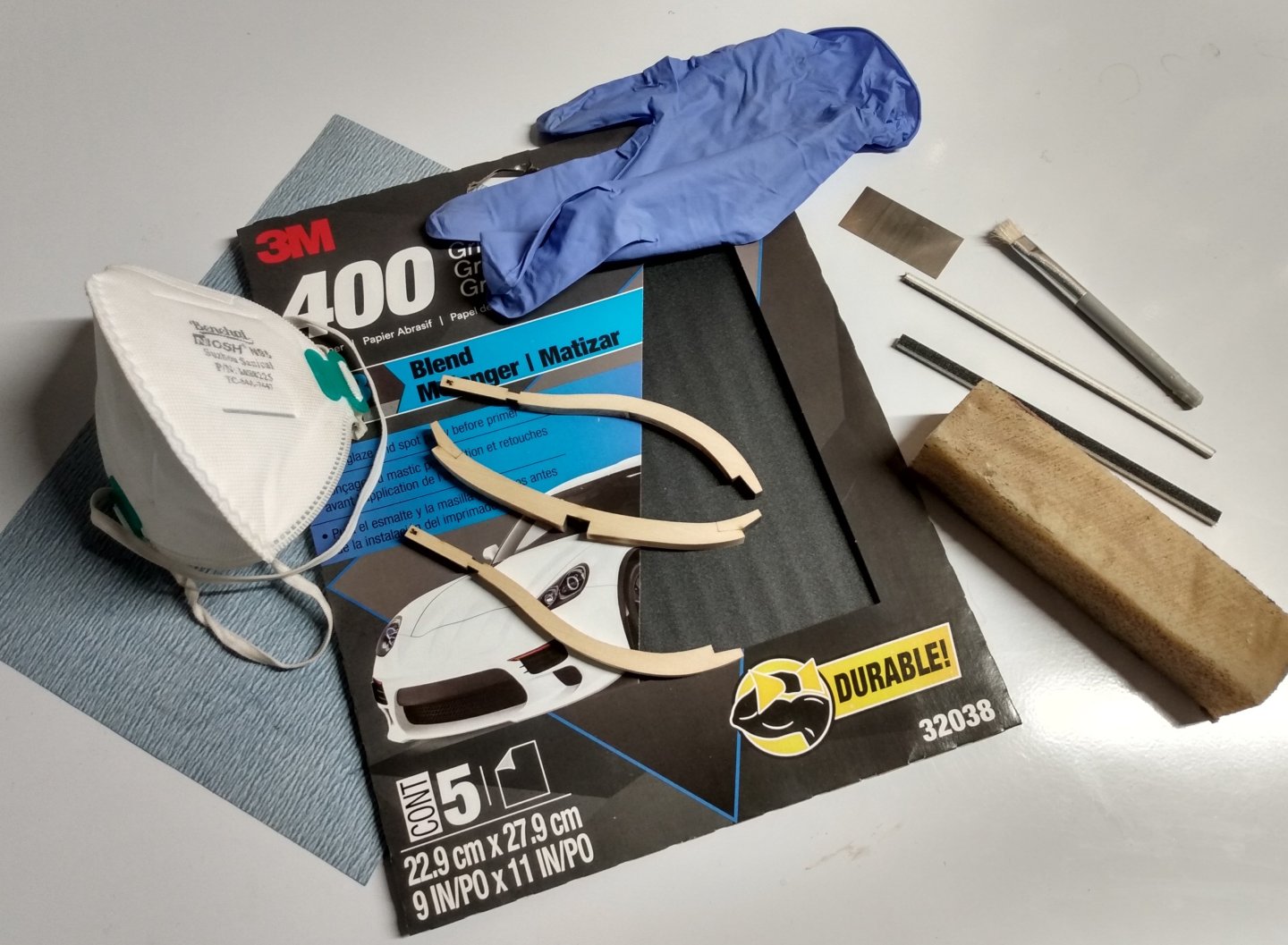
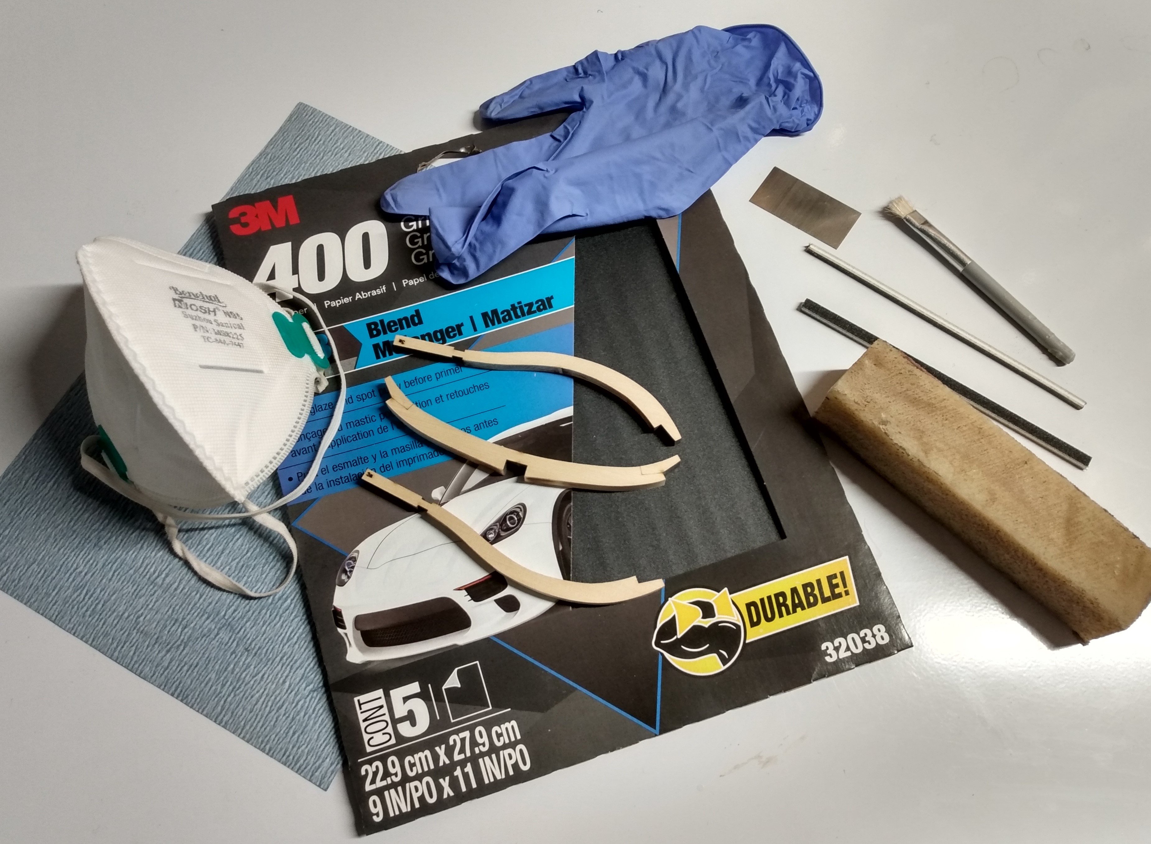
The next step is removing of the char on the frame parts. The layer of char on those parts is quite thick and cleaning them up requires a fair bit of work. The photo below shows the tools and equipment I used for this task. Char from the hull (concave) side of the frame can be removed using sand paper. First using standard woodworking 400 grit sand paper and then finishing with waterproof automotive 400-600 abrasive paper. I find the later works very well. Since it is black, every sanding stroke is clearly seen so it is easy to move your part around to clean areas at every stroke (sanding over a dirty section of the sand paper just imbed the char within the wood fibers). Once the sand paper sheet is saturated with char, it can easily be cleaned by soaking in water, dried and reused. For the inside of the frames (convex regions) I first used Lee Valley's mini scrappers. Most of the char can be remove this way. A clean surface is achieved with further sanding with sanding sticks of diamond needle files. I use a crepe block to frequently clean the sticks and files from accumulated char. Otherwise the char removed is simply moved around. With the same idea in mind, it is a good idea to keep your working area clean by frequent wiping/vacuuming. All this is done wearing a N95 mask (a must) and optional nitrile gloves.
Frame preparation is a slow process. It took me about three weeks to complete the square frames. By the end, I could complete one frame in about one hour.
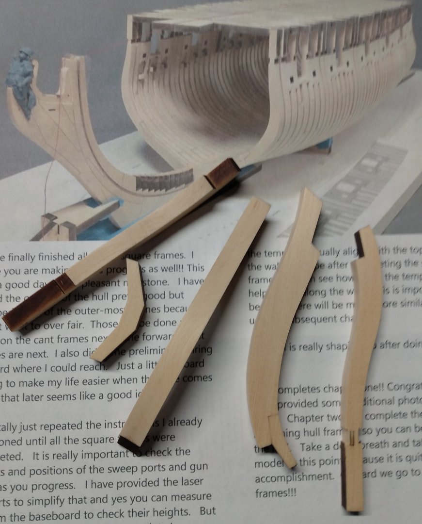
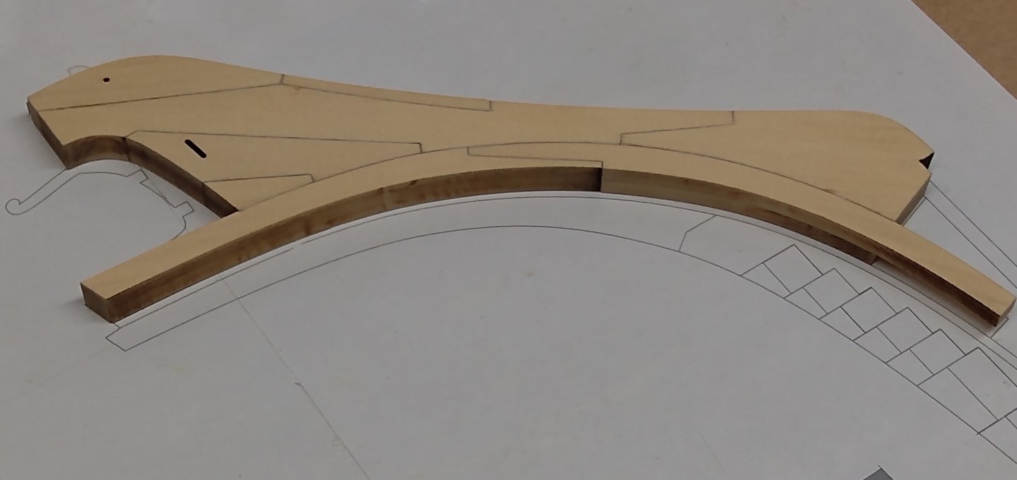
Once the char removed, I also sanded the frame sides to remove any residual char. An example of a completed frame (10f) is shown here. Note the misplaced notch in one of the parts (lower right hand corner) for this particular frame. This is the only part that shows such anomaly. Hard to understand how this could happen in the production process. If others see the same it could indicate a mistake in the drawing file used with the laser cutter.
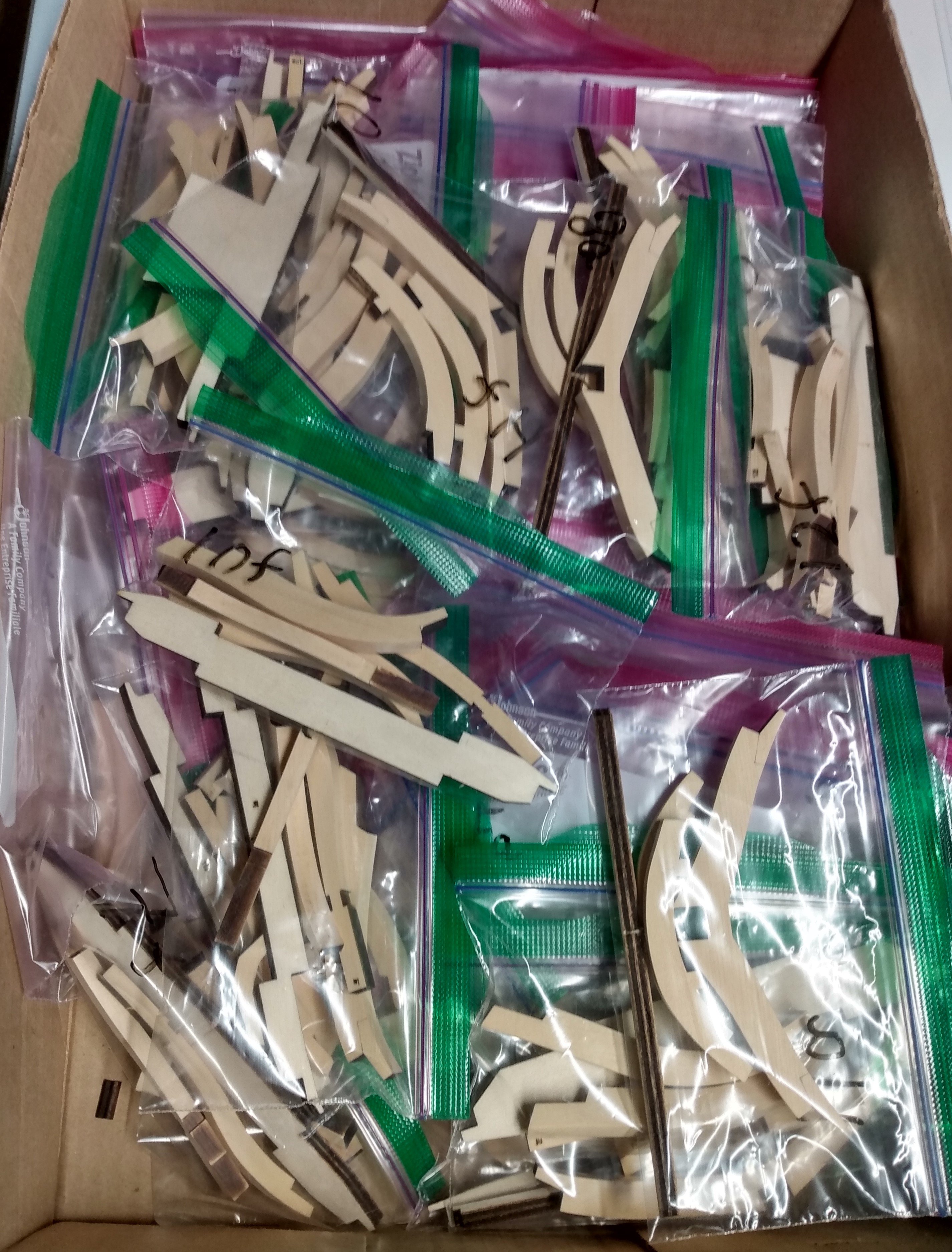
The next step is the frame assembly. At this point I am wondering whether or not WOP should be applied to the sides prior to assembly? It is not clear to me how the frame sides can be finished once assembled (how to deal with the various steps when scrubbing with a steel wool) or installed on the keel (limited access). I welcome suggestions. I am also trying to devise a method to keep joints as tight as possible and minimize skewedness of assembled frames. The photo below shows all the frame parts s in individual ziplock bags ready for assembly.

- Stuntflyer, Freebird, dvm27 and 9 others
-
 12
12
-
Thank you all for the likes.
Stern Post
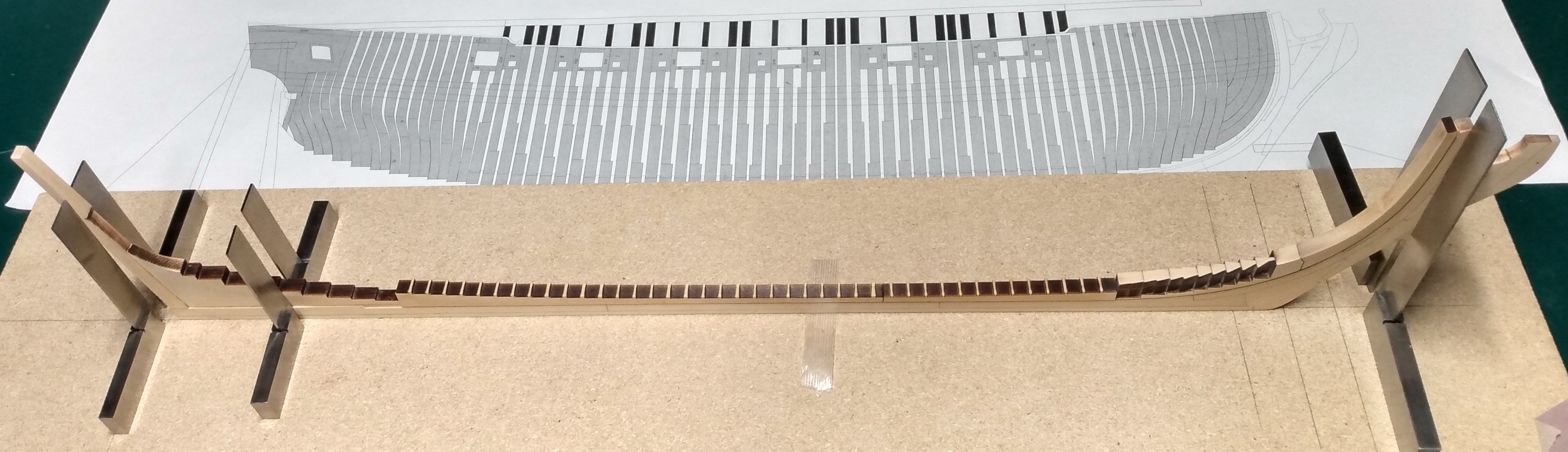
While most of the keel parts were glued on a flat surface, this proved problematic for the stern post. With the rising wood protruding and the stem taper, the assembly is no longer flat and it is difficult to proceed the same way. To keep the stern post perfectly vertical, centered and aligned to the stem, I rather used squares to keep the whole assembly vertical and aligned. See photo.
I applied a couple thin coats of WOP on the completed assembly. I show close-ups of the stern and stem below (note the knee of the head finally glued on).

After application of WOP the wood got a bit darker than expected. Does WOP have a limited shelf time when opened? In the past I have used nitrocellulose sealer. This is great stuff. It does not change the wood color, gives a nice satin finish and dries almost instantly (70% of the content is VOC!). It is however a pretty nasty chemical and it is hard to find (banned in North-America?). I got mine from the UK many years ago but nowadays suppliers will not ship this abroad. I find WOP a good alternative.
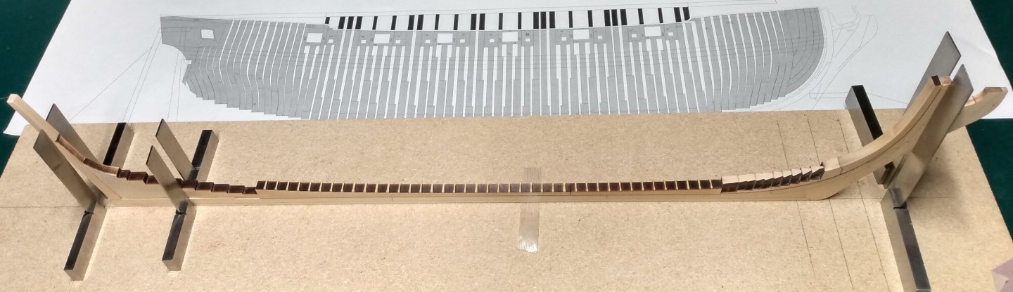
Building Board
This has been covered by others and I essentially followed their foot steps. The MDF boards I could find in hardware stores were not flat. I resorted to a melamine board and glued my plan with repositionable spray glue. It is now time to work on the frames. Stay tuned.
- dvm27, Ryland Craze, davyboy and 9 others
-
12
-
Lower/Upper Apron
The pre-cut curved rabbet is a nice feature which avoid the headache of bending and adjusting a straight strip and gluing it to the stem. I had to tweak the curvature at the stem to get a tight fit between the lower and upper apron. I found it tricky to optimize the seam on both sides at once. A lot of back and forth was required here. The final result is shown below.

The Rising Wood
Before gluing the rising wood sections, I realized that the strip supplied for the rabbet was a touch thicker than the curved section. I fixed this easily using my Varitas mini-plane. The rising wood then went on with no particular issues. Care should be taken to insure that the position of the rising wood is not shifted with respect to the plan. For this I used a plan that I had printed at my local printer.
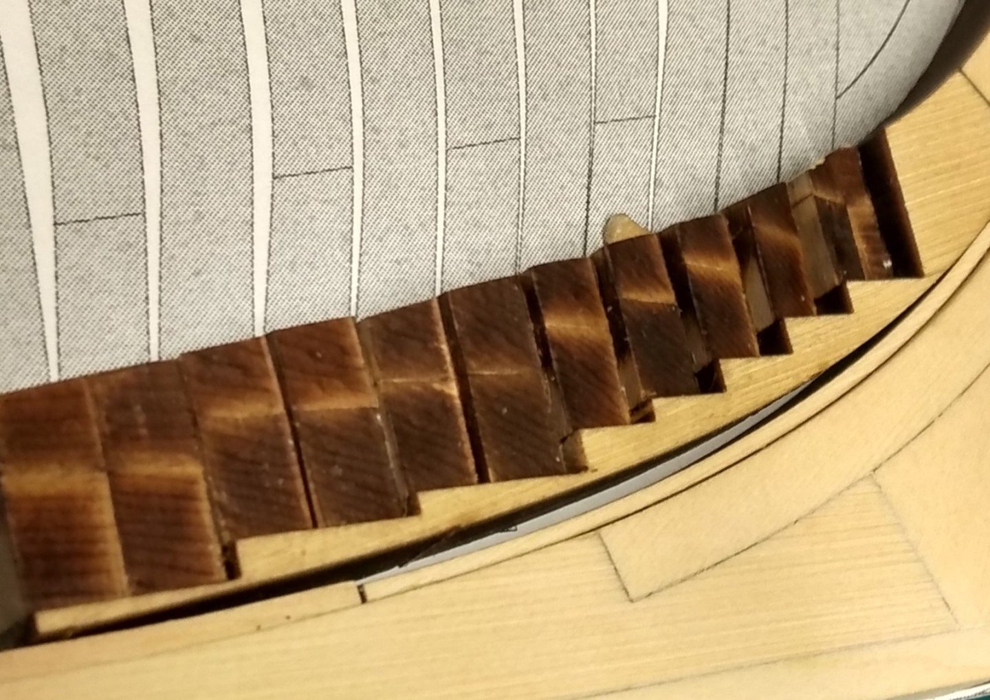
The Deadwood
I followed the instructions with no particular issues here. Gluing the angled wedges is easier than at the bow. The completed assembly is shown below.
- westwood, Seventynet, sfotinos and 10 others
-
13
-
Thanks Greg. I tried magnification loupes and they don't work well with me. I suffer from strong myopia and presbyopia. My myopia is such that my far point (distance at which a far object is in focus) is actually closer than my near point (distance at which a close object is in focus). I found that the best way to work is to not wear any glasses and keep the object I am working on at the far point distance (about 12-15cm). Then the object is in perfect focus. The price to pay is a total lack of depth of field, which becomes a problem when aligning/gluing larger elements.
-
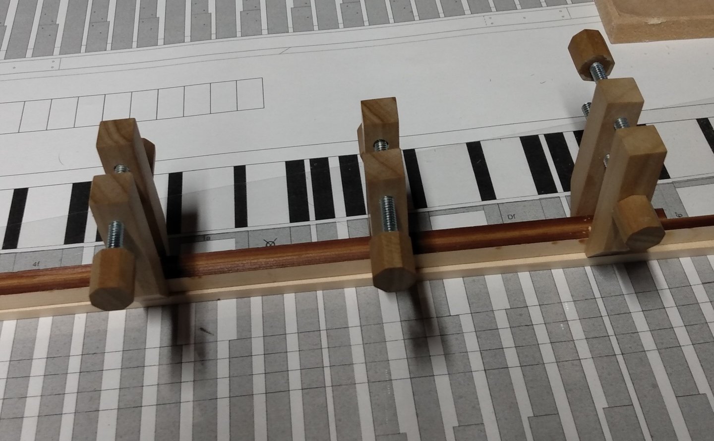
The Keel Assembly
The main challenge here is to make a tight fit at the boxing joint between the keel and stem. I had to shorten the curved stem just a touch to get a good fit. The rest of the keel assembly is a matter of gluing the various sections in the right order and on the right side. Very little tweaking of the edges is needed. While I was waiting for my kit, I built a set of simplified "Ed Tosti" clamps. I find these work better than commercial clamps to apply even and adjustable pressure to the parts being glued. They are kind of fun to make too.
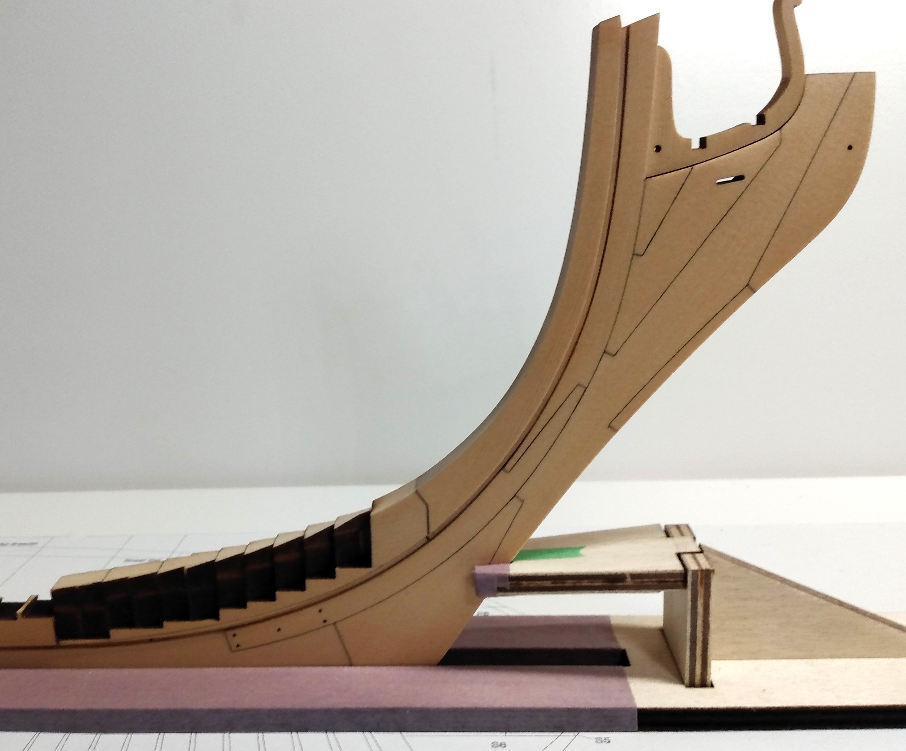
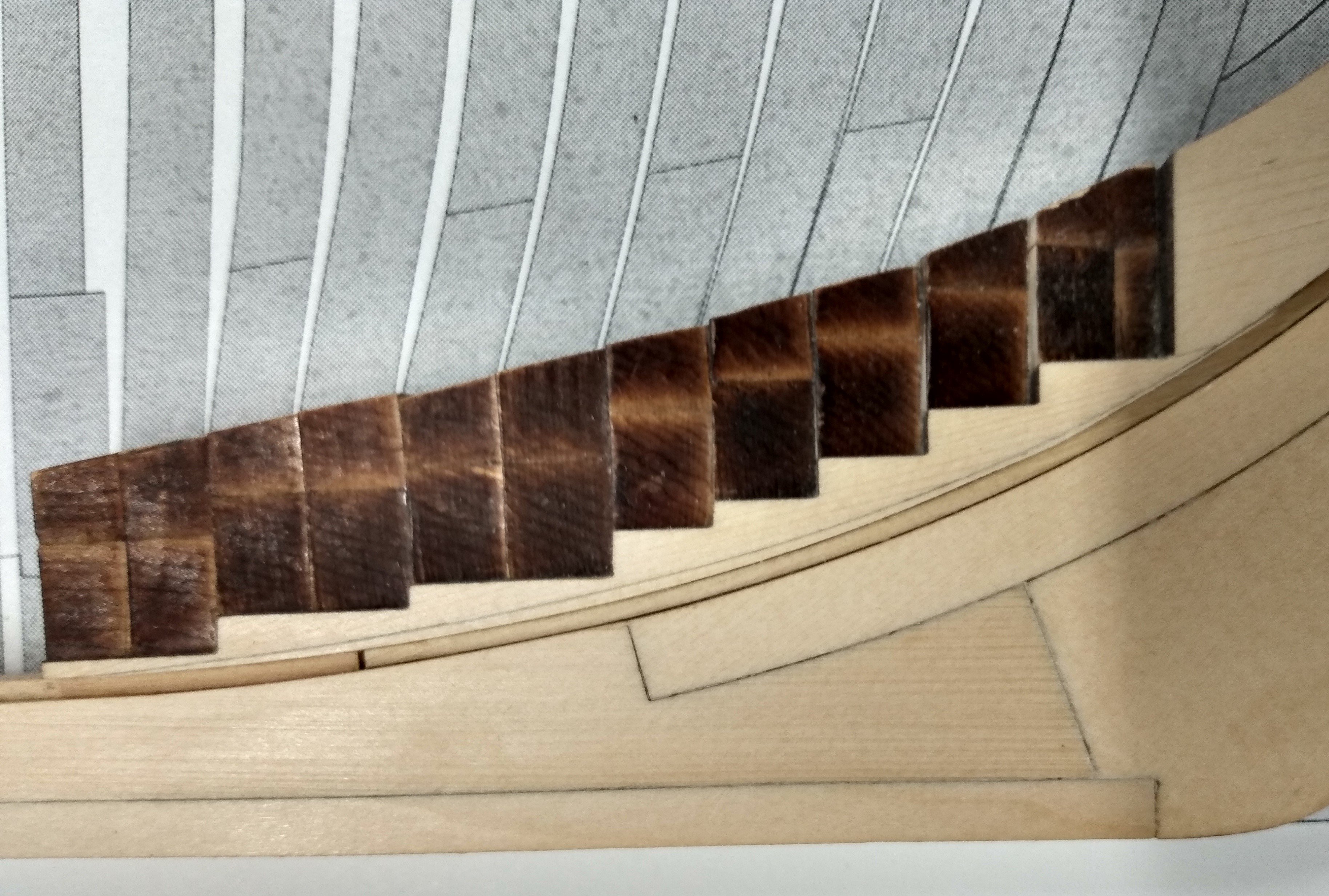
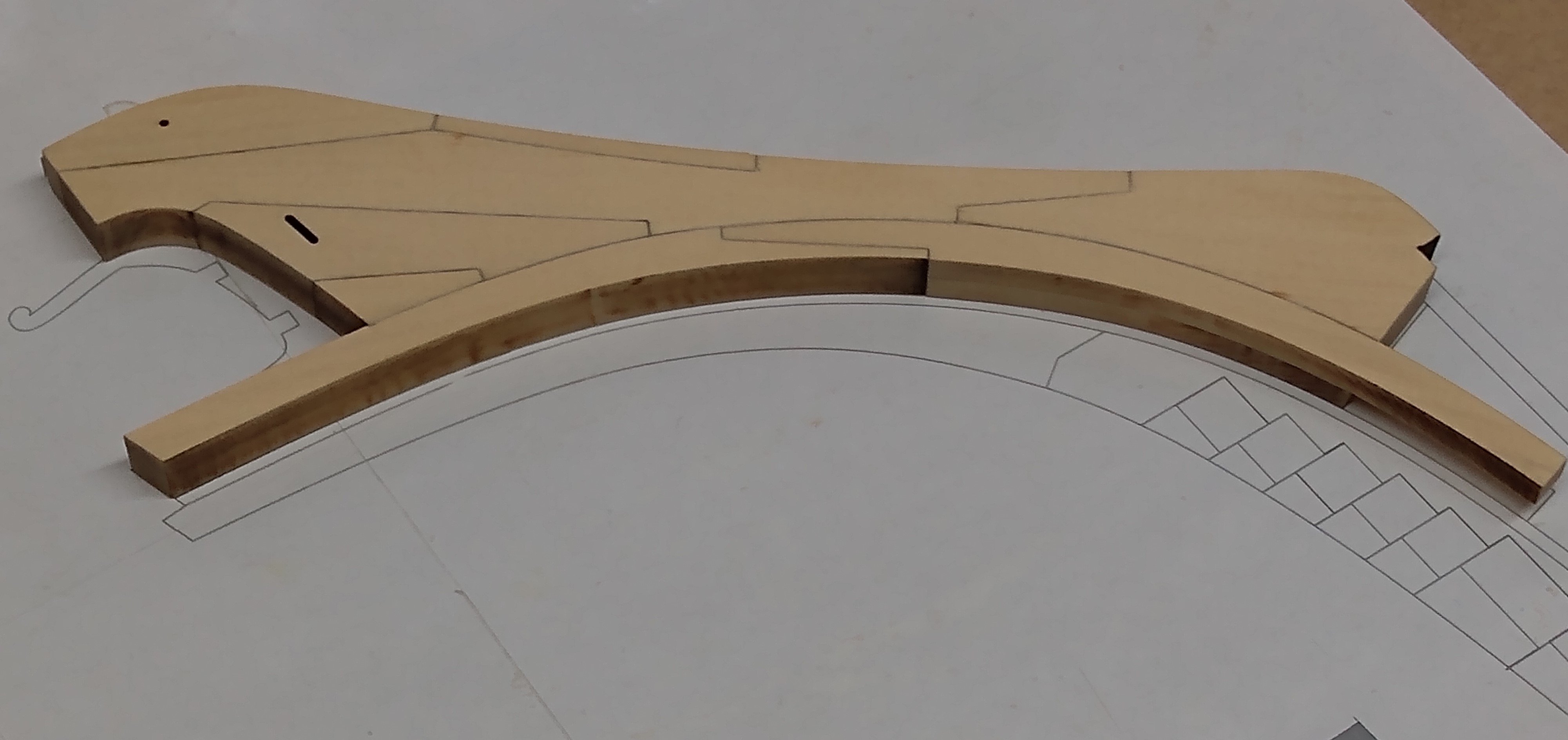
Lower Apron and Angled Wedges
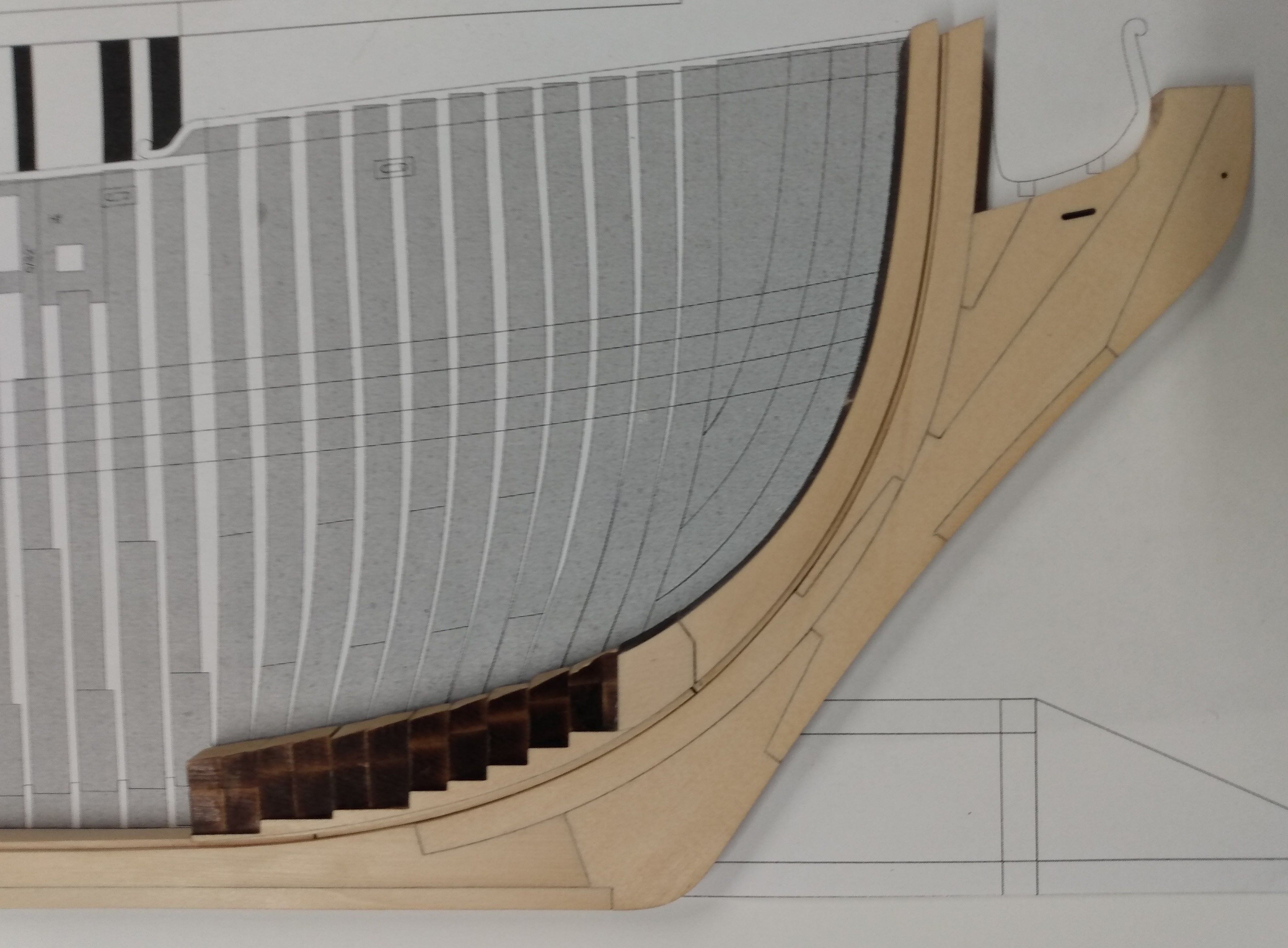
Here I encountered my first difficulty. The stepped lower apron is attached to a sacrificial piece of wood (handle). This makes it easier to glue the wedges one by one. Without the handle, the lower apron would certainly break during this operation. I found that even with the handle, the lower apron remains quite fragile. If you force the wedge in position, you can slightly modify the curvature of the apron or even break it loose from its handle. This happened to me and resulted in a poor fit of the lower apron to the keel assembly as shown below.
I was able to correct this by gluing a sliver of wood between the apron and the keel as shown here.

This gap may also have been the result of the stem being glued a hair too low (less than 1/32th). Anyway, I am glad that I took the time to correct this.
-
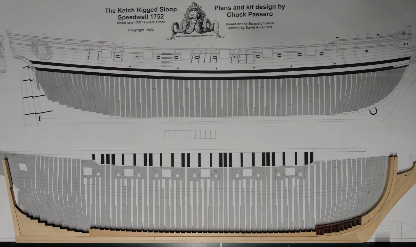
CHAPTER 1
Here we go. I started ship modeling about 15 years ago. I completed all Chuck's projects plus a few others (including Model Shipways Syren). I recently completed the Winchelsea and posted a few pictures on the gallery. Except for Chucks Medway, all my projects had been POBs. I was therefore quite excited when the Speedwell kit was released. This offers me a great opportunity to work for the first time on a POF kit without having to scratch my own frames. Except for ripping planks on my Byrnes saw (yes I am among the lucky ones), I essentially work with hand tools. In this blog I will report on my progress. All the Speedwell builders are well experienced, and I am hoping you guys can provide advices when I have questions or encounter difficulties. Thanks in advance. (This will also free Chuck from answering my numerous emails). On occasion, I hope I can contribute some ideas and tips to those who will undertake this project.
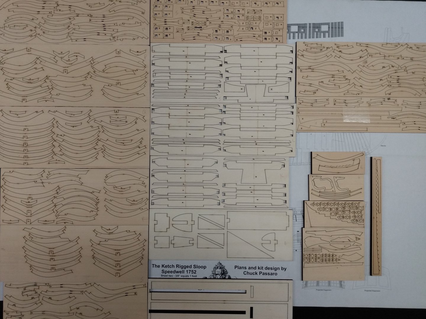
Parts for Chapter 1 are shown below. Contrary to others, my kit survived posting very well. Only one small part (5F) in the top center board seems to be missing. It is easy to scratch build, so no big deal.
Assembling the stem is straightforward. Tweaking the edges as suggested improves the fit. I had to tweak a few more edges than those indicated to get the tightest fit.
Positioning the stem (long curved part to which the rabbet is glued) on the rest of the stem assembly can be tricky. It is important to follow the plan closely to avoid problems when making the boxing joint at the keel and to ensure a tight fit between the apron and the rabbet. I think I glued mine a hair too low and had to make adjustments (to be discussed below). Note that I postponed the gluing of the thinner knee of the head for the time being. To prevent knocking it off, it will be glued on only when the whole stem/keel/stern assembly is completed.
- Chuck, westwood, AnobiumPunctatum and 7 others
-
10
-
-
Hello all,
I recently started this project and will be reporting on my progress in this blog. Stay tuned.
Jean-Marc
- sfotinos, Ryland Craze, yvesvidal and 5 others
-
8
-
To add to the discussion, I have used both PVA and CA in my model building for the last 12 years. I first used PVA for planking, which I found challenging. It could be messy, it requires clamping, especially at the bow and stern. About six years ago, I switch to CA for planking, following Chuck;s method. I find CA a lot easier to use and the resulting plankling a lot more satisfactory. You can get very thight joints with CA without use of clamps. There is no need to apply glue to the edges, minimizing glue stains. It is also a lot more forgiving at the bow and stern. If your plank bending is not perfect. Just hold the plank in the correct position for a few seconds until the glue sets. I first used BSI products but recently switched to Gorilla gel. I really like the latter product and found it performed just as well as BSI. The gel gives you a few seconds to adjust pieces, it alo minimizes splills and stains. The glue dispenser is also very well designed. The spout never clogs, which I found could be a problem with BSI bottles.
Jean-Marc
-
I join the voice of others congratulating you for completing the project. What a spendid model and how fun it is to build it! Your ability to come up with creative solutions at difficult and critical parts of the build is quite remarkable. I still have many months (years?) in front of me to reach the finish line. Hopefully, in time to embark on a new journey with your forthcoming POF project.
Kudos again.
Jean-Marc
- Edwardkenway, Ryland Craze, druxey and 3 others
-
6
-
One end of the wire in the vise the other in the mandrel of your hand drill. Give it a quick spin (5-10 turns). The wire will become perfectly straight. This also affects the micro-crystalline structure of the wire making it a lot more rigid.
Jean-Marc
- Bob Cleek, thibaultron, Canute and 1 other
-
4


Sloop Speedwell 1752 by sfotinos - Syren Ship Model Company - 1:32 Scale - POF Sloop
in - Kit build logs for subjects built from 1751 - 1800
Posted
Nice Shawn,
I am also making frames. I did a quick check with frame Ba (Aa not done yet). My frame is also slightly inside the line (less than 1/32 on each side). I was quite aggressive with my char removal and this could have slightly reduce the width of the frames. Also, a frame not perfectly square with the respect to the keel or slightly higher on one side than the other will bring the frame limit inside the line. I am curious to see if I get closer to the limit line once I have made all the necessary adjustments. I will keep you posted.
Jean-Marc