KeithAug
-
Posts
3,986 -
Joined
-
Last visited
Content Type
Profiles
Forums
Gallery
Events
Everything posted by KeithAug
-
 Nils, congratulations on your "launch" she looks every bit the king of the seas.
- 2,625 replies
-
- 4
-

-
- kaiser wilhelm der grosse
- passenger steamer
- (and 1 more)
-
Dear Julie The J Class gods are quite traditional and I think they may reserve judgement until they see how it turns out - particularly in respect of how you sort out the all important deck gear. I think the way you are thinking that the 2011 refit arrangement of winches, tracks etc may be the way to go. http://www.adamlaystudio.co.uk/wp-content/uploads/2014/05/Endeavour-Boat-International-July-2012.pdf
-
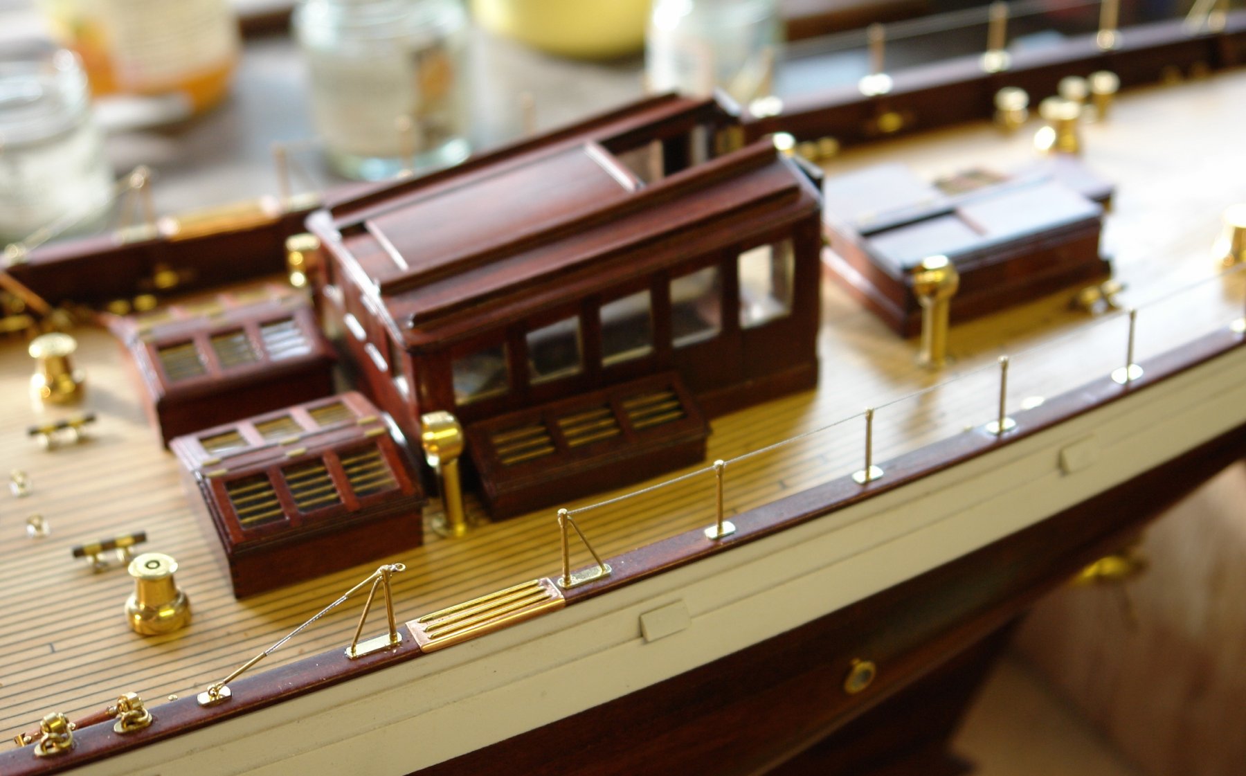
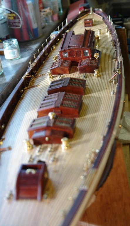
And so another post prior to yet another enforced break. At the end of the week my son gets married to his long term girlfriend. I did wonder whether it would ever happen as he is imfamous for some of his quotes e.g: When he and his soon to be wife were out together with friends he was asked:- "Paul why don't you jet get on and propose to her?". Quick as a flash he respond with:- "I'm 95% sure that she is the one for me, but that means their is a 1 in 20 chance that someone better will turn up". Fortunately no one better turned up. Back to the build and once again thank you Julie for your comment and thanks to all those who have visited. I finished the guard rail. It took a bit of time to make the attachment features - they were all very small. The guard wire was .020 clear plastic coated stainless steel wire. For £2 I have enough to last several lifetimes. I attached one end of the wire and held the other end taught with an elastic band while the CA glue dried.

-
Julie My preferred order would be to plank the flat deck and then sand it and finish it before attaching anything that stands up above it. Trying to sand the deck planking around an upstanding deck house etc., just complicates the sanding.
-
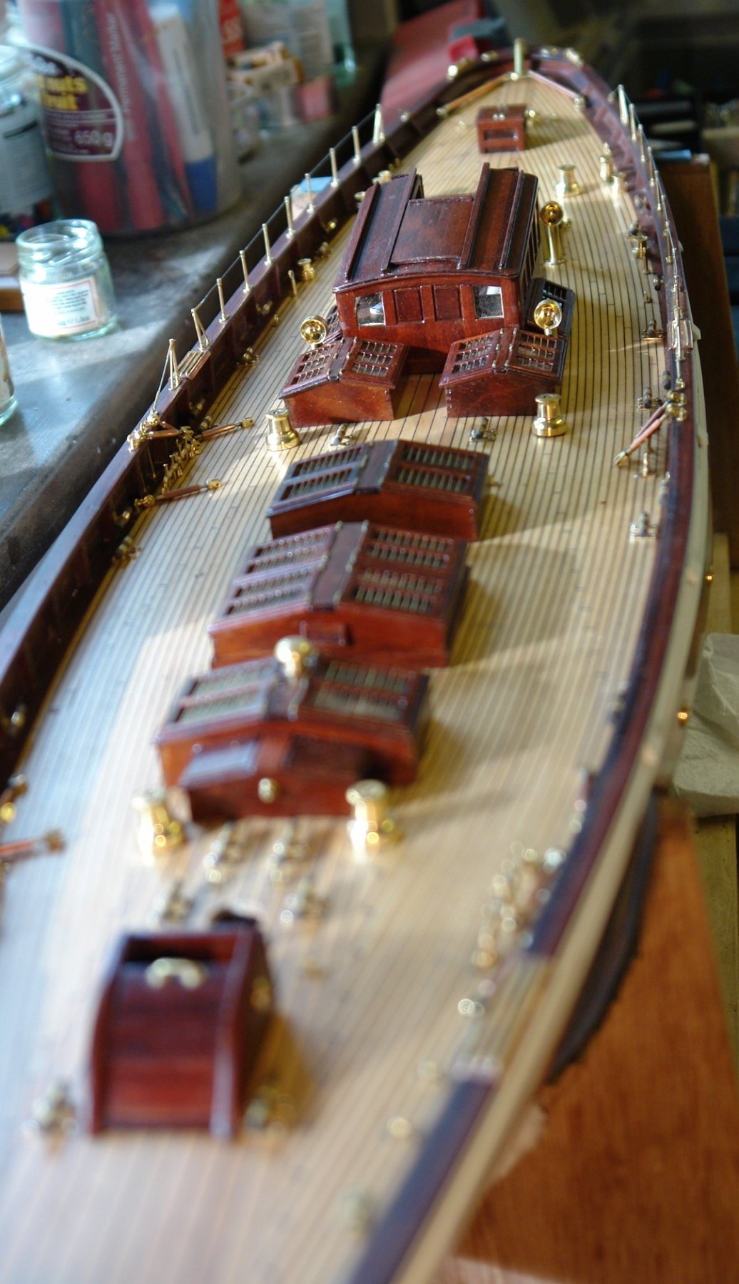
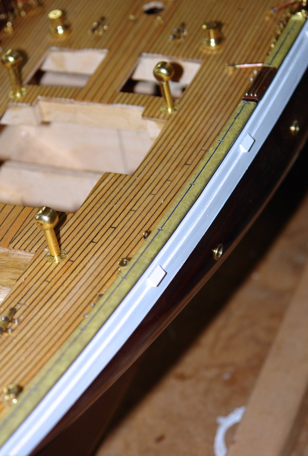
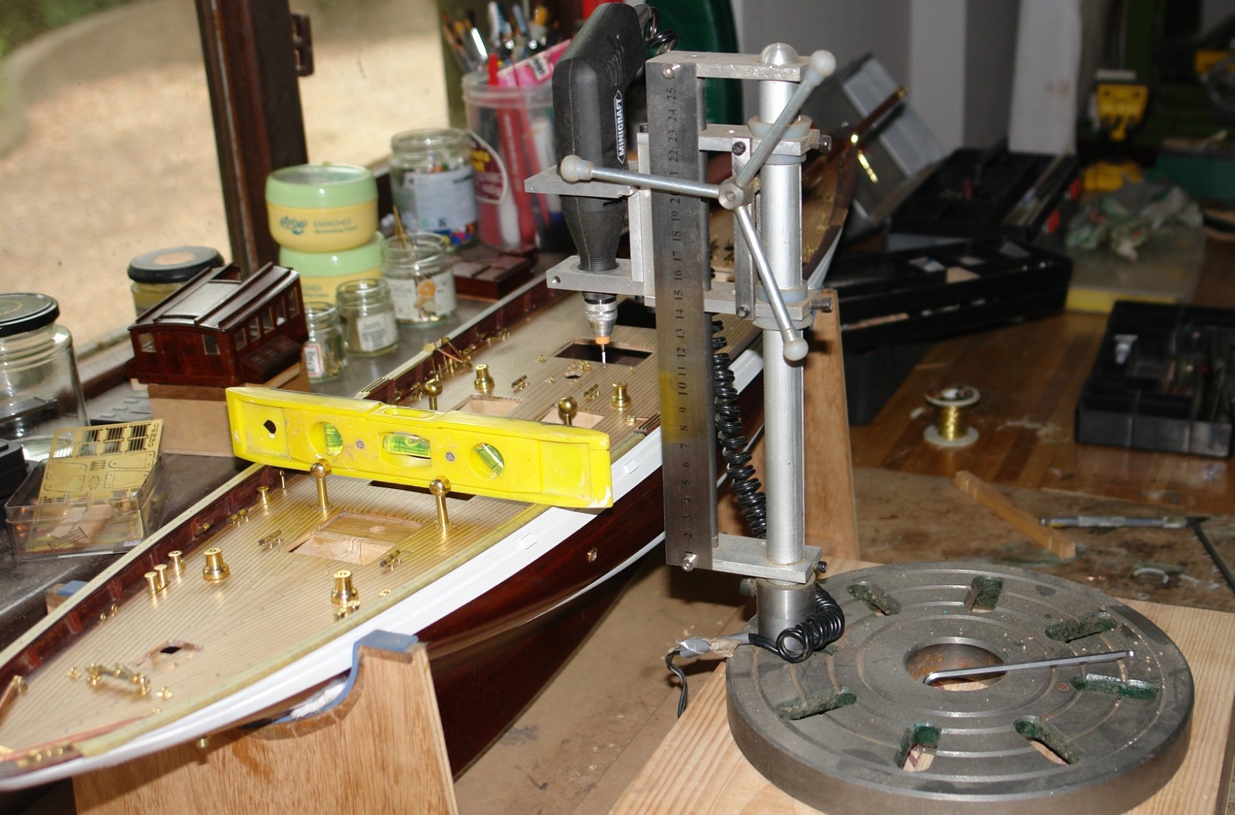
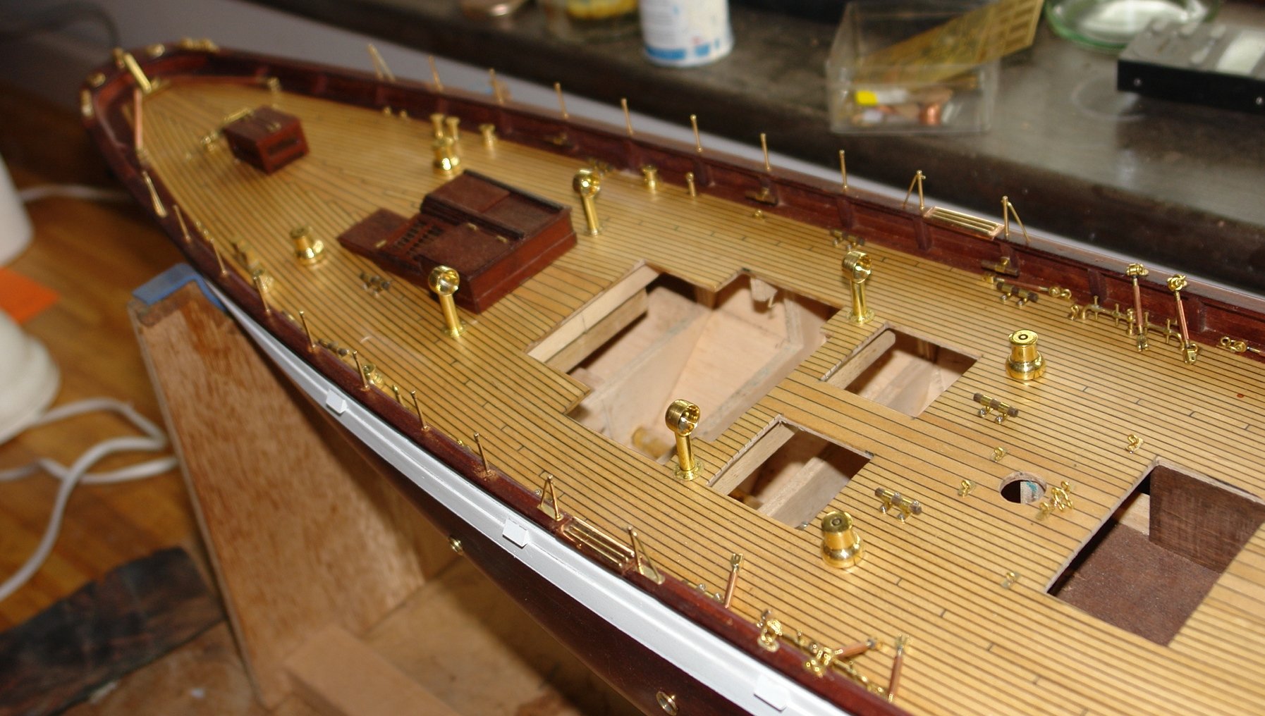
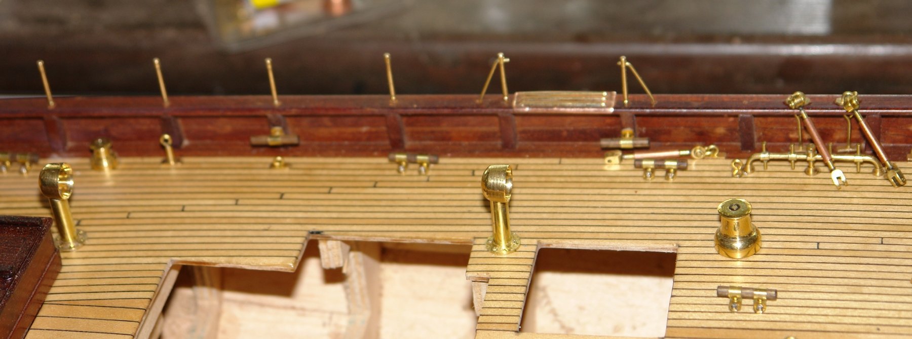
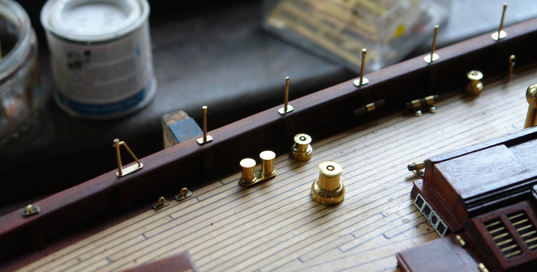
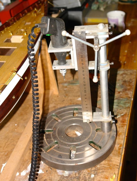
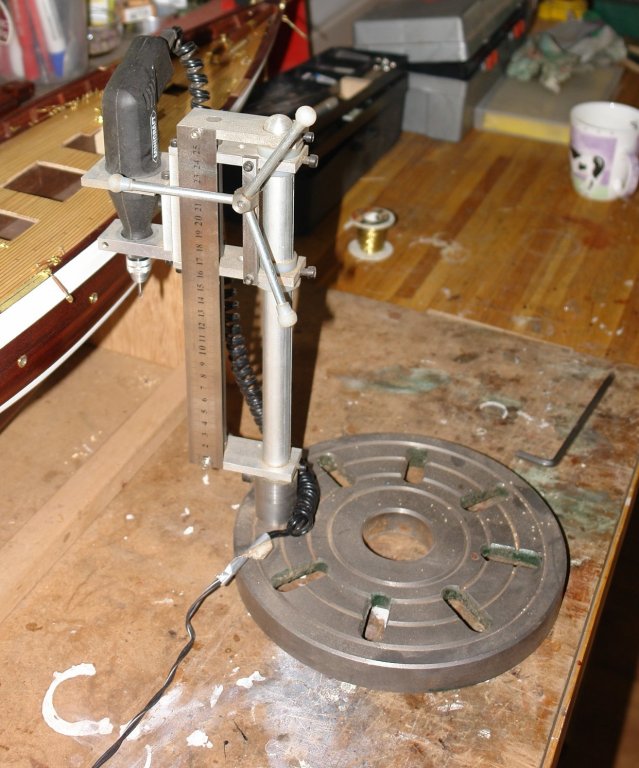
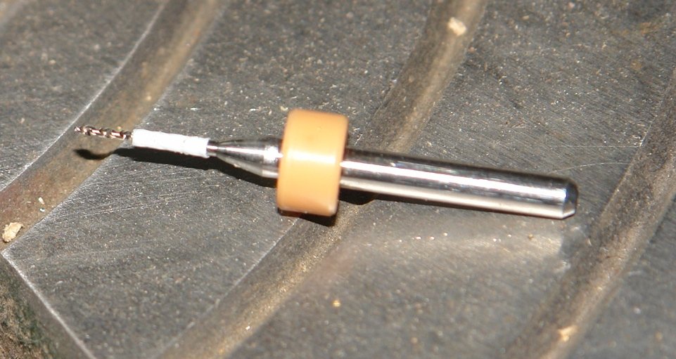
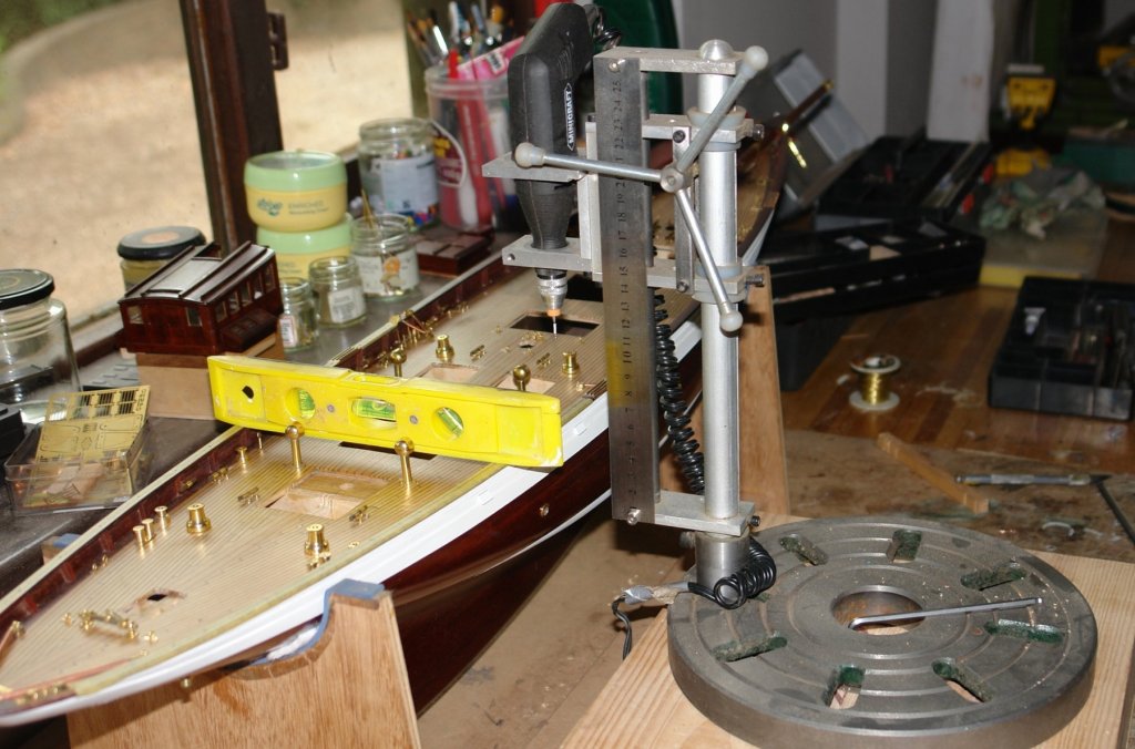
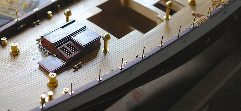
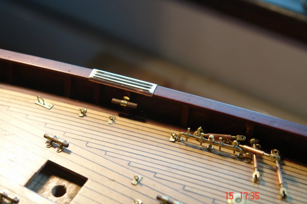
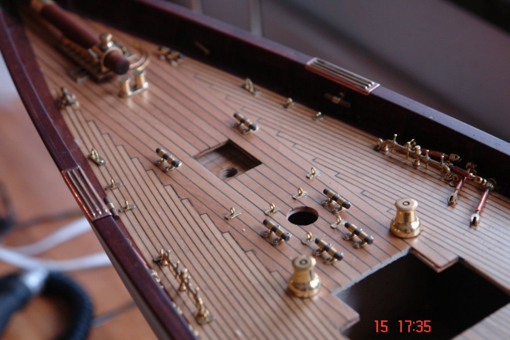
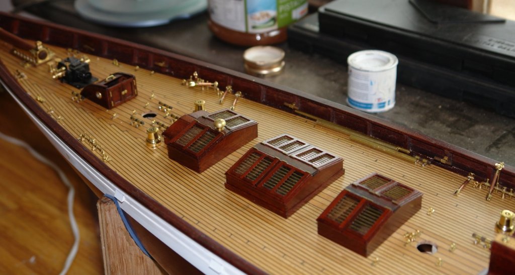
John / Julie - Thank you. The next task was to get on with mounting the guard rail stanchions. The trick was to get them all truly vertical - and hence parallel. Each stanchion sits above one of the bulwark ribs so axial positioning was relatively straightforward. I stuck a strip of masking tape along each rail and marked out the stanchion line on this. With the positions marked it was time for drilling. My home made drill press has the advantage that the pillar can be rotated round thus allowing holes to be drilled which are outside the surface of the base plate, making the accurate drilling of stanchion location holes a simple task. I needed to make sure the drill didn't penetrate too far at the stern - drilling trough the hull would have been very annoying. I find putting a sleeve on the drill works very well as a depth control. All drilling had to be done with the hull sitting true along the waterline and level across the beam. At 6 positions the stanchions are reinforce with bracing struts - to take the tensile loading of the wire guard rail. All stanchions have feet, made by the same technique as used for the deck eye feet. The stanchions are currently in place awaiting gluing.


-
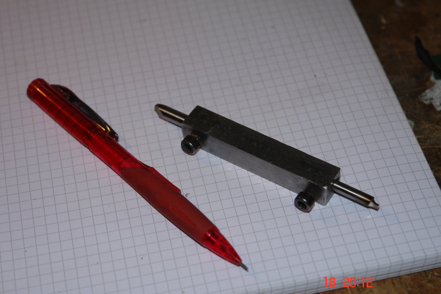
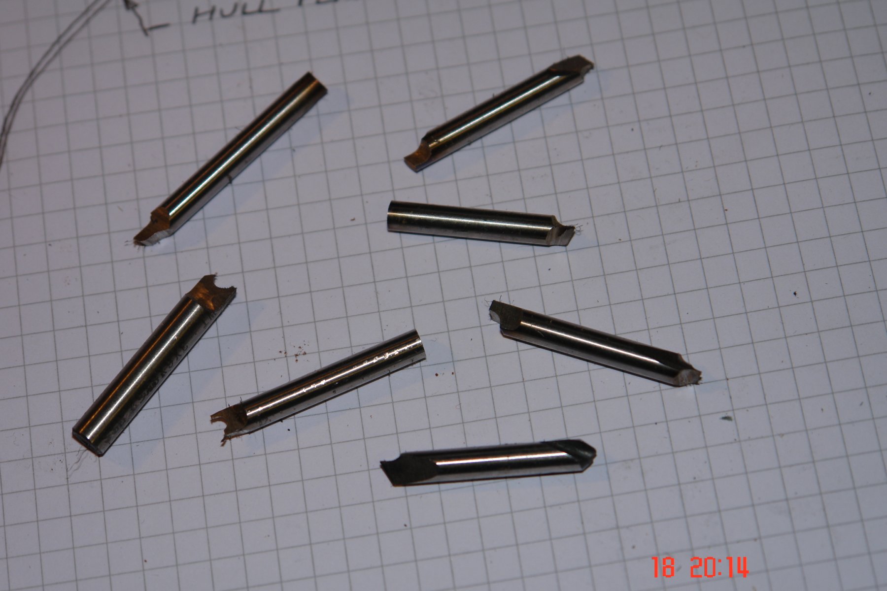
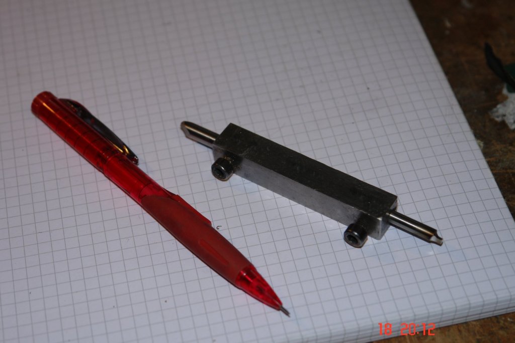
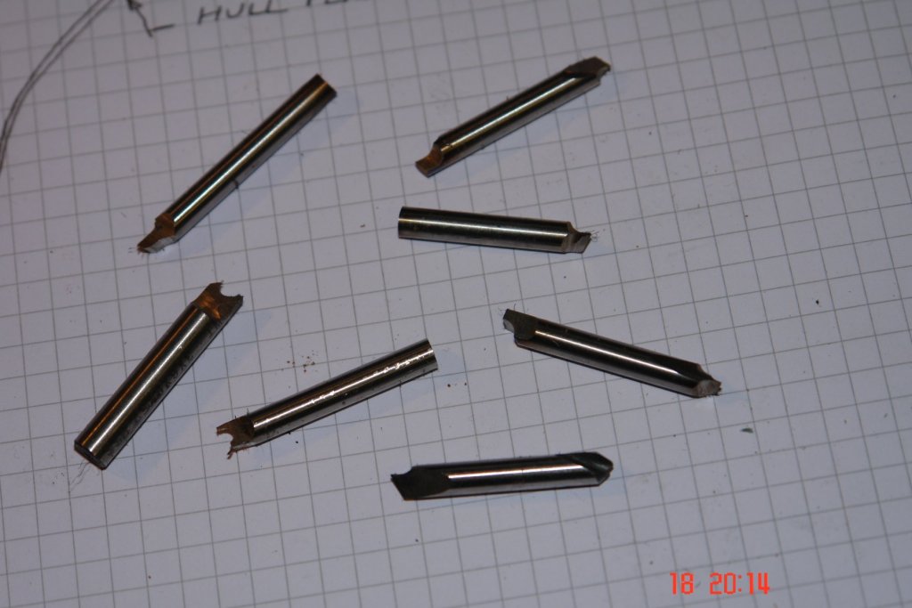
Michael Thank you for the feedback. I'll try your flattened wire trick. JD I find normal lathe tools too large for the more detailed work so I grind small tools out of broken centre drills or small diameter HSS blanks. I use 2 diameters - .1875" and .225". I have drilled out a section of square bar to hold them - one tool on each end, held in place by a cap bolt. I need to get round to making more holders.
-
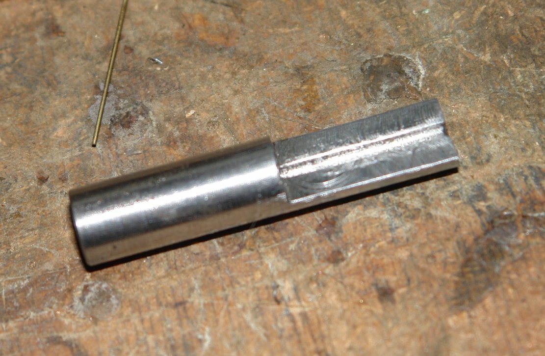
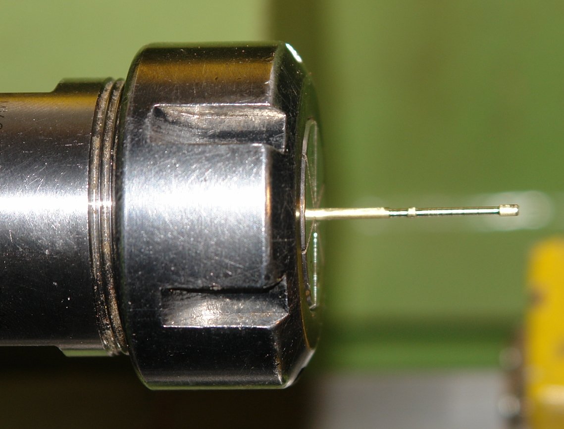
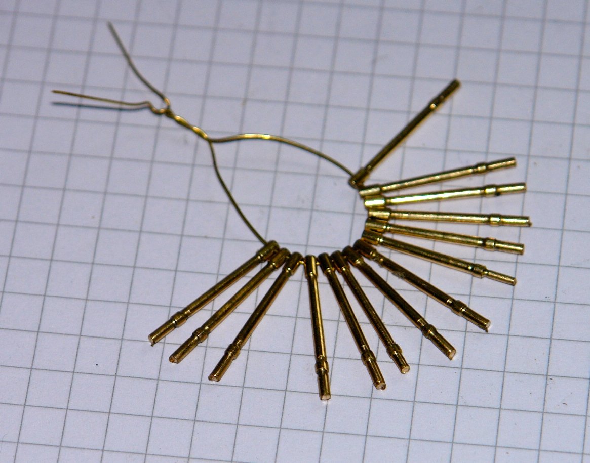
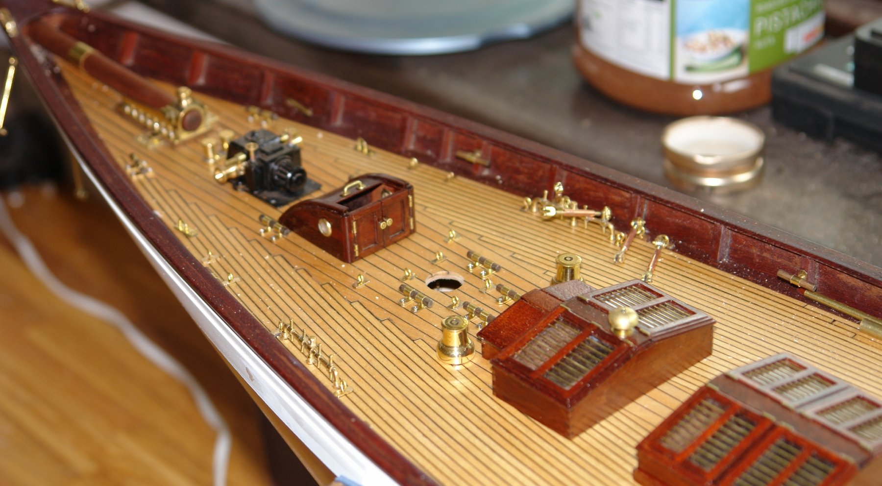
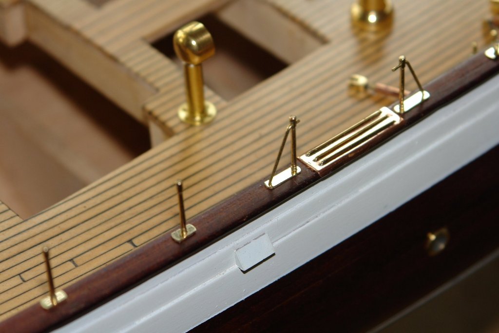
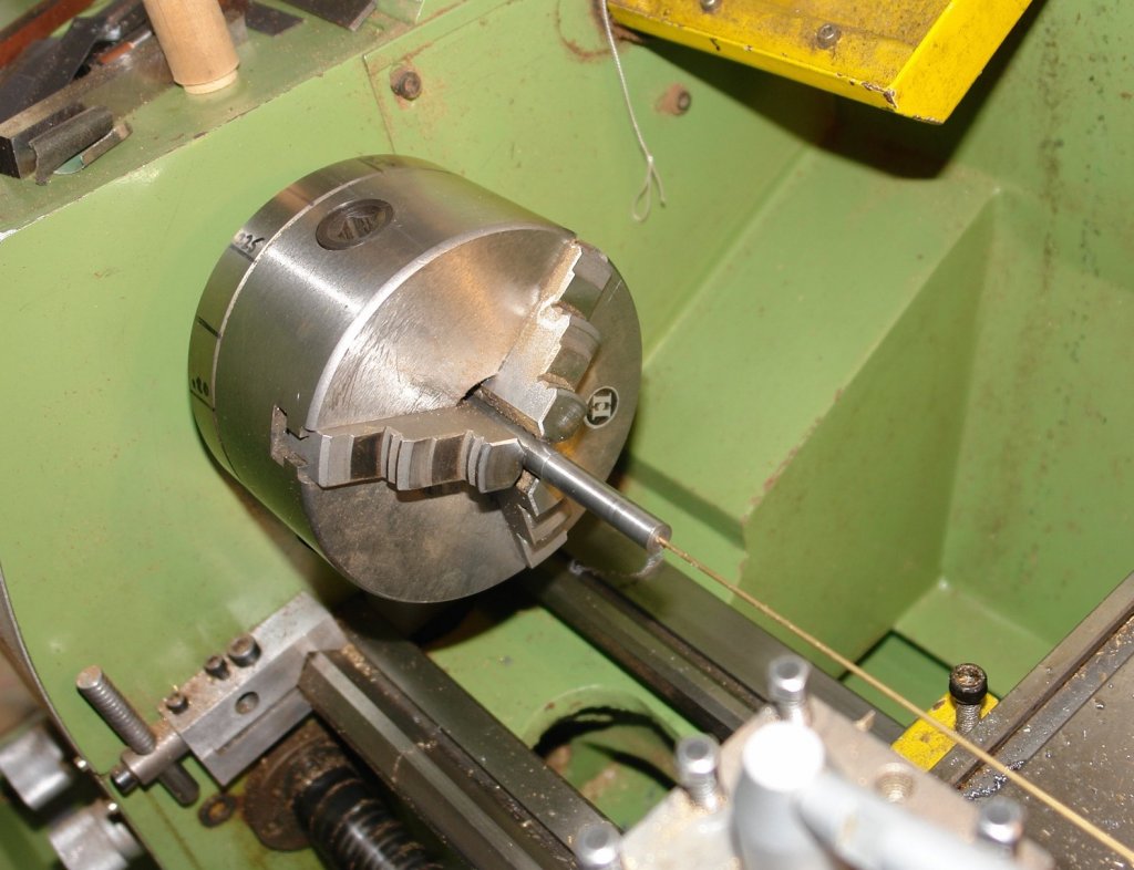
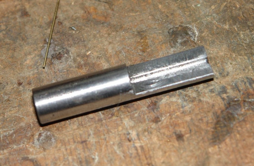
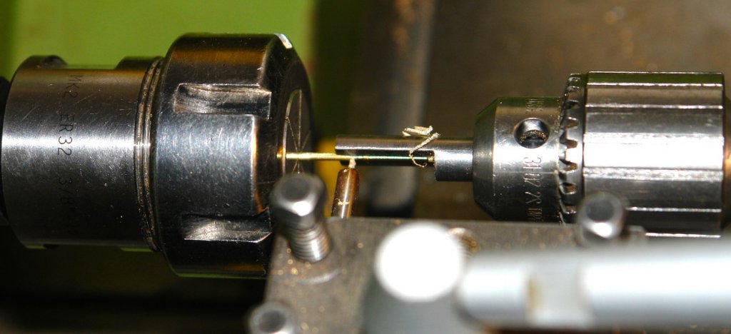
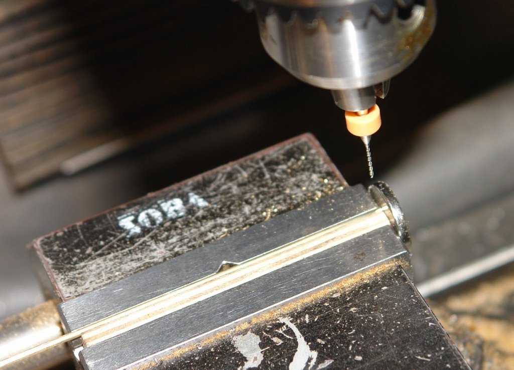
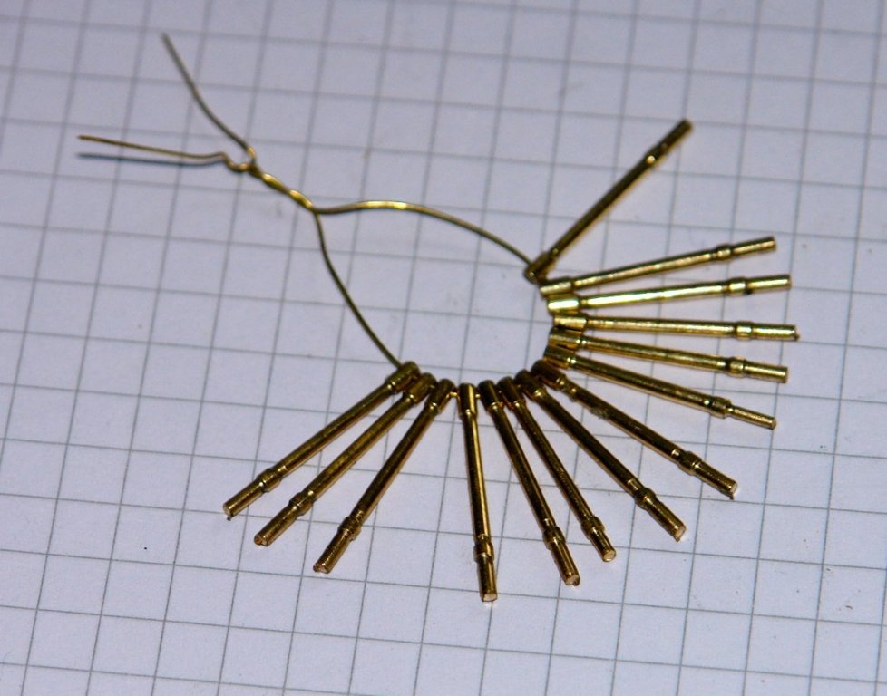
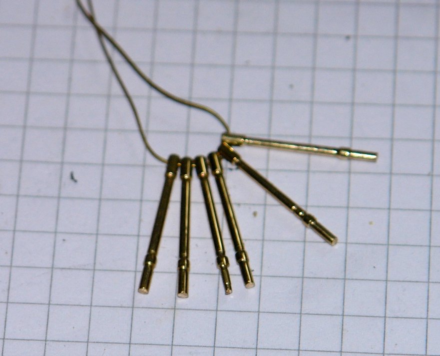
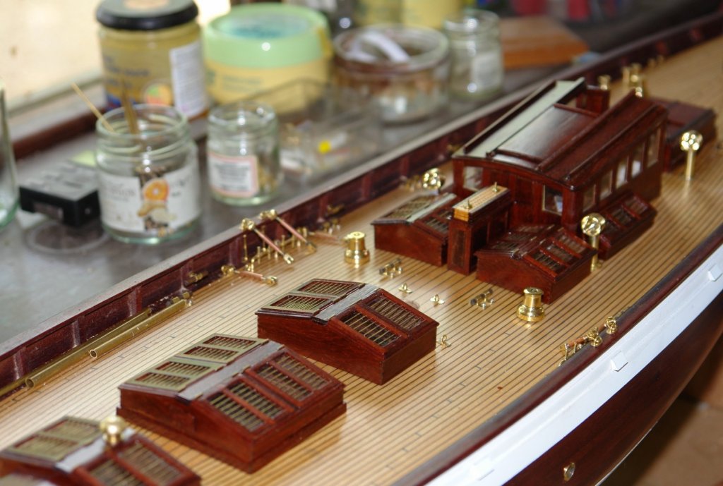
Altair has demountable stanchions with a single wire rail which run from amidships to just before the stern. At scale size the stanchions are .600" long. I made them from .062" brass rod with a machined waist of .048". 14 of the stanchions have a single hole at the end while 6 have double holes - the second hole taking the 45 degree bracing strut. The first operation was machining the .032' diameter cross hole in the plain brass rod. The mill was set up to drill the hole with the rare earth magnet end stop set to reproduce the axial position. The wood inset has a .040" x .040" notch cut along its length to provide horizontal location while providing the clamping surface. .062" brass rod is too flexible to turn without support so I made a support out of .375 steel bar - drilled with a .062" hole and then milled to half its thickness. This forms a slot support which fits in the tailstock chuck. Each stanchion took about 15 minutes to make. Mistakes for Herask:- I drilled 2 holes in the wrong place - plugged with dowel - I think I will make a rope mat to cover them as they are in front of a deck hatch. I also cut one deck plank a little short. Also best bot to use the wood stain above the finished deck - I think it will sand out.


-
HMS SUSSEX 1693 by 8sillones
KeithAug replied to 8sillones's topic in - Build logs for subjects built 1501 - 1750
Magnificent internal detail and carvings. Very impressive. -
Good to see the shipyard reopened Mark. A bit more info on the laser cutter would be great.
-
ancre La Salamandre by tadheus - 1:24
KeithAug replied to tadheus's topic in - Build logs for subjects built 1751 - 1800
Pawel - it would be good to know how you cut the slots? -
Beautifully neat craftsmanship Dan. She is turning out really smart.
- 287 replies
-
- 2
-
-
- michelangelo
- ocean liner
- (and 1 more)
-
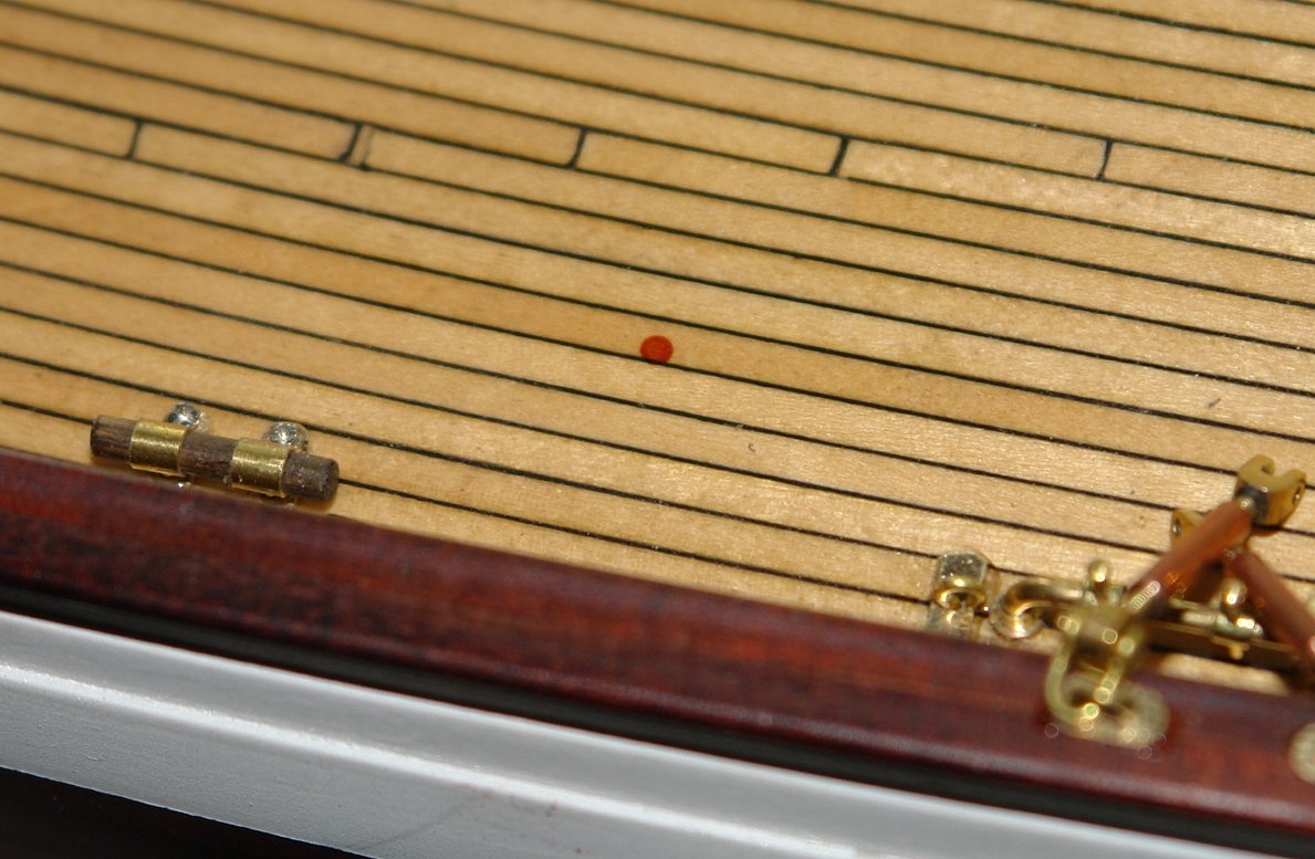
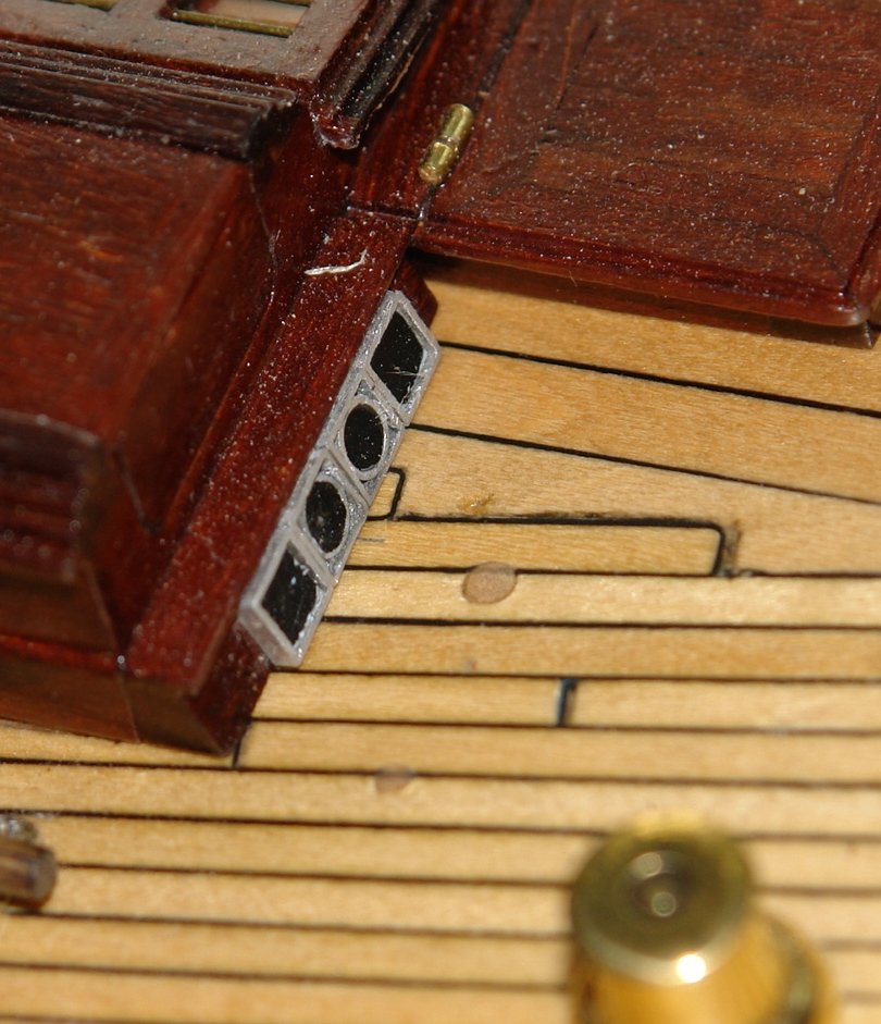
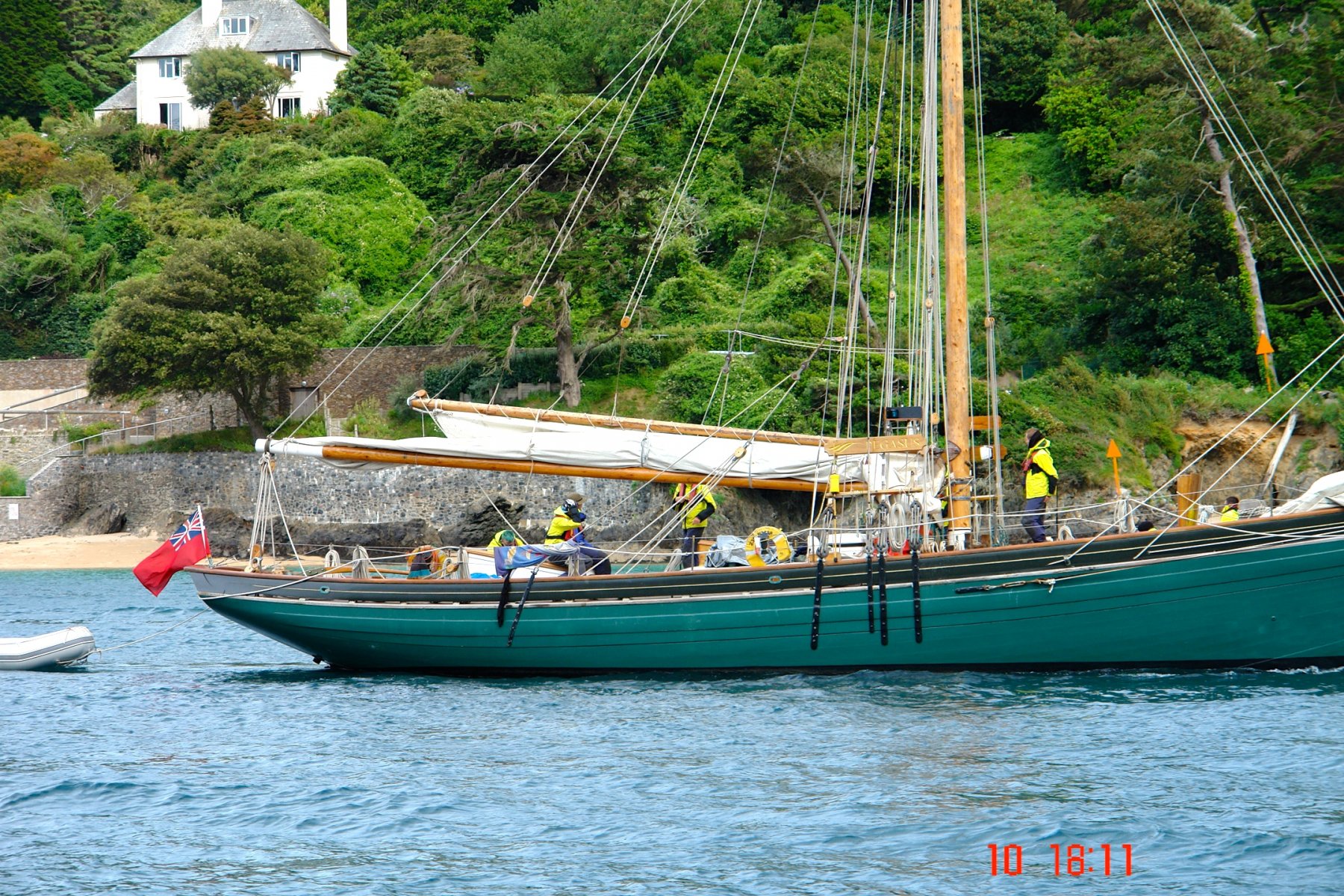
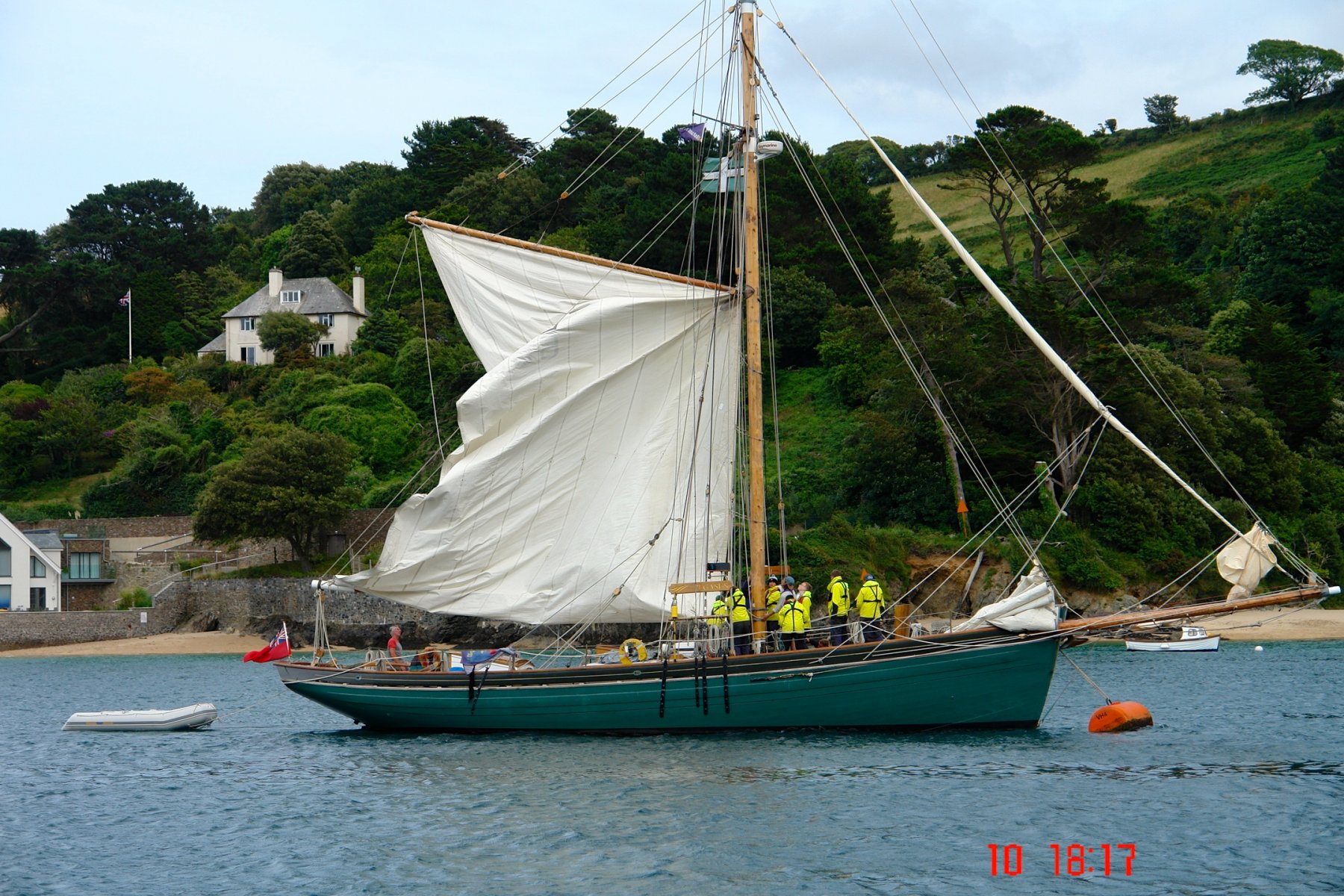
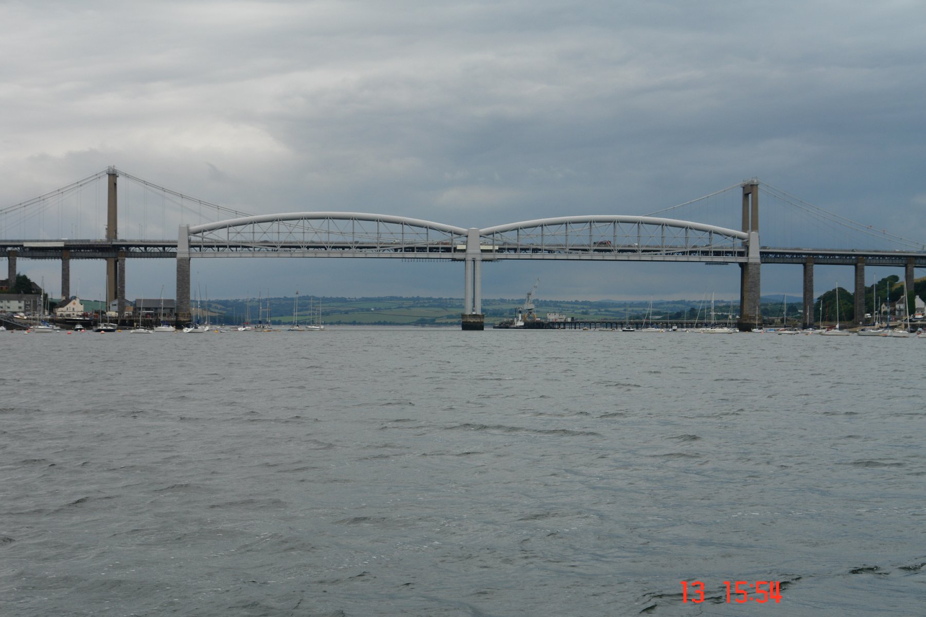
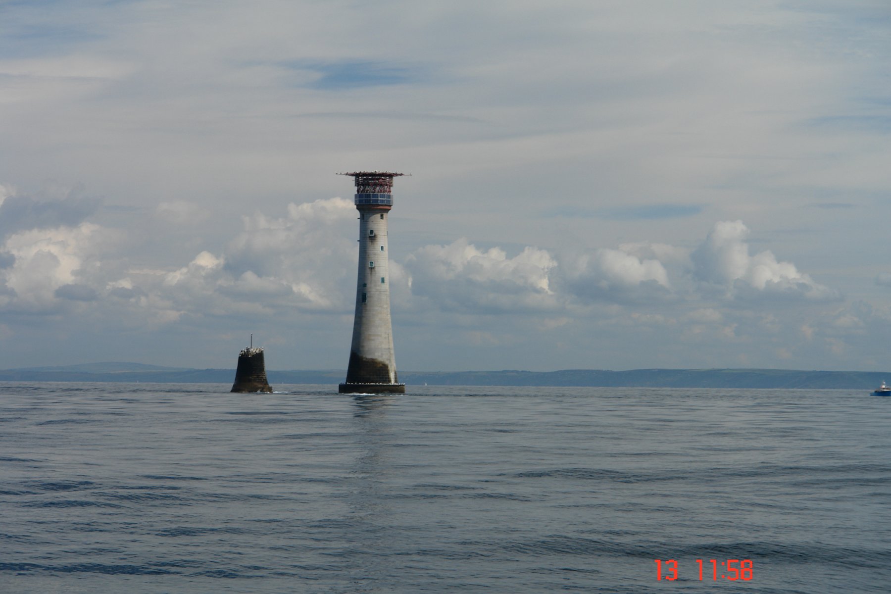
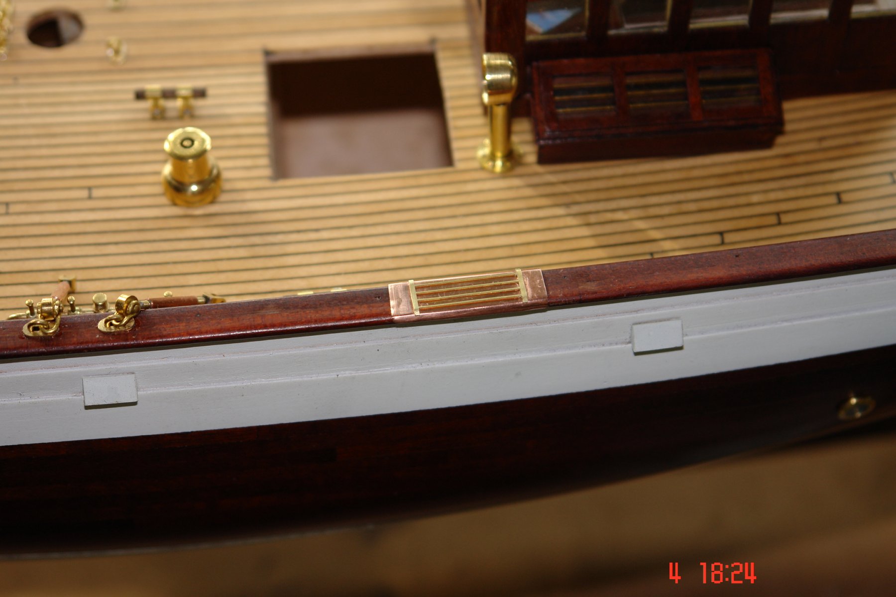
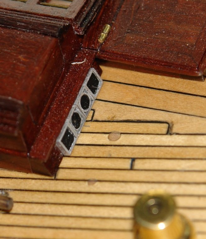
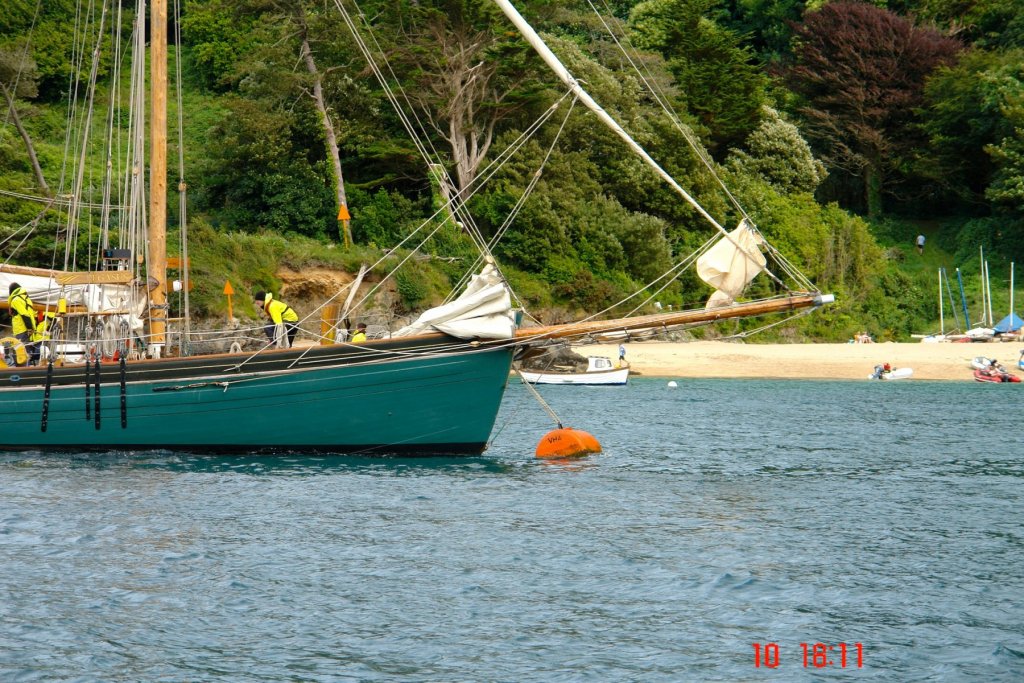
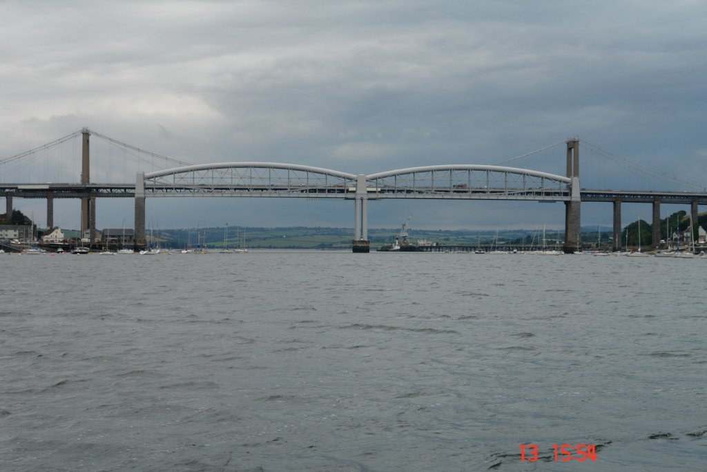
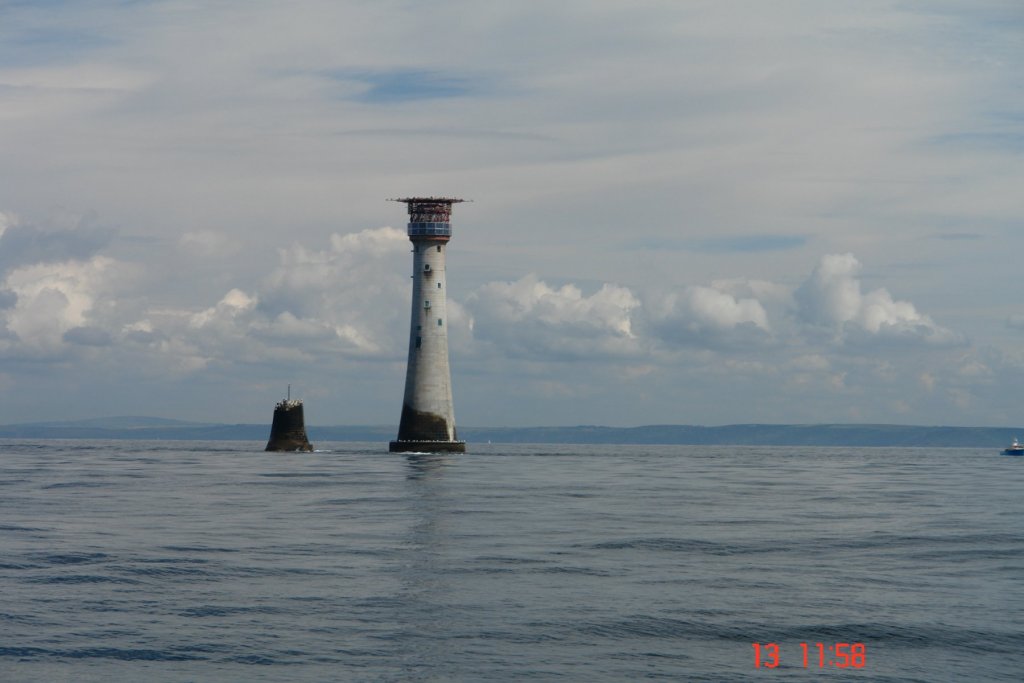
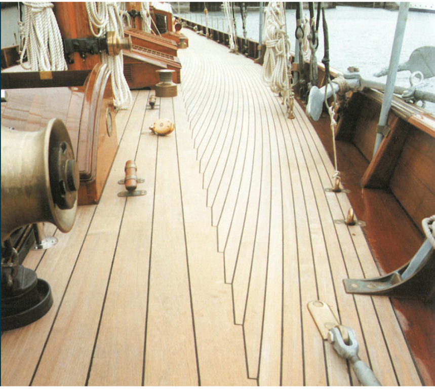
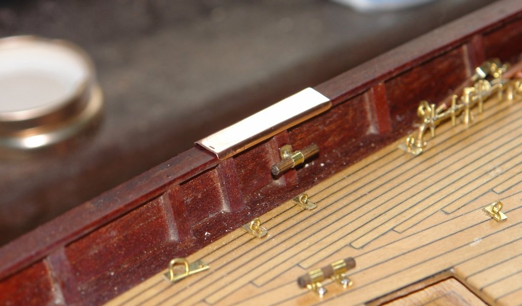
Herask - thank you, i'll see what i can do about mistakes. I'll photograph a few for the next post. I arrived back from sailing yesterday. I'd been thinking about the rail protective plates and decided I could do better. Today I drilled the plates and soldered on wire strips instead of the glued on etchings. I was happier with the result as it looked more like the original. I also collected a few interesting shots from the holiday....................... We came across a replica of a Bristol Pilot Cutter. I have a few more shots for anyone interested. Up a creek we found a few laid up ships one of which was Triton an experimental trimaran warship. We sailed under Brunel's Tamar Rail Bridge, completed in 1859 and still impressive (although a little spoiled by the modern suspension bridge behind it). We also paid a visit to the Eddystone Light - the site of the worlds oldest offshore lighthouse. The current light dates form 1882. The stump is the base of the previous light which was completed in 1759. It was disassembled and re-elected some 12 miles away on Plymouth Hoe a few hundred yards from the Mayflower Steps. 4 lighthouses have been built on the site - the first one dating from 1689.


-
Bedford, thank you - Glad you are not jealous, it would be out of character for an Aussie. Richard - thanks for the sailing good wishes. Hoping for decent weather. Druxey - glad you found the build - still a long way to go so hope you find time to visit again. Thanks also to all other visitors, hope you all found someting of interest. Now off to pack.
-
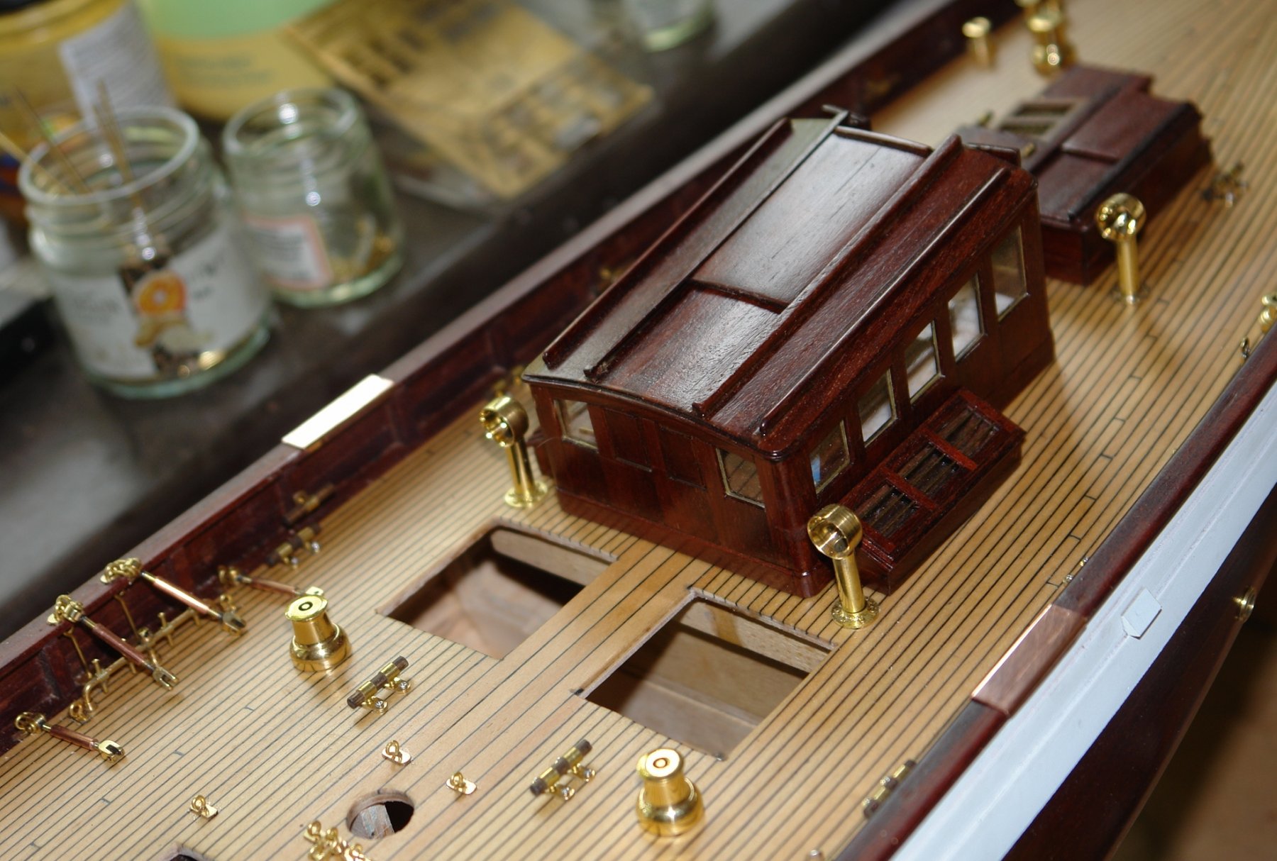
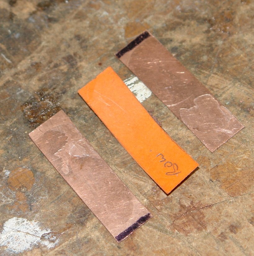
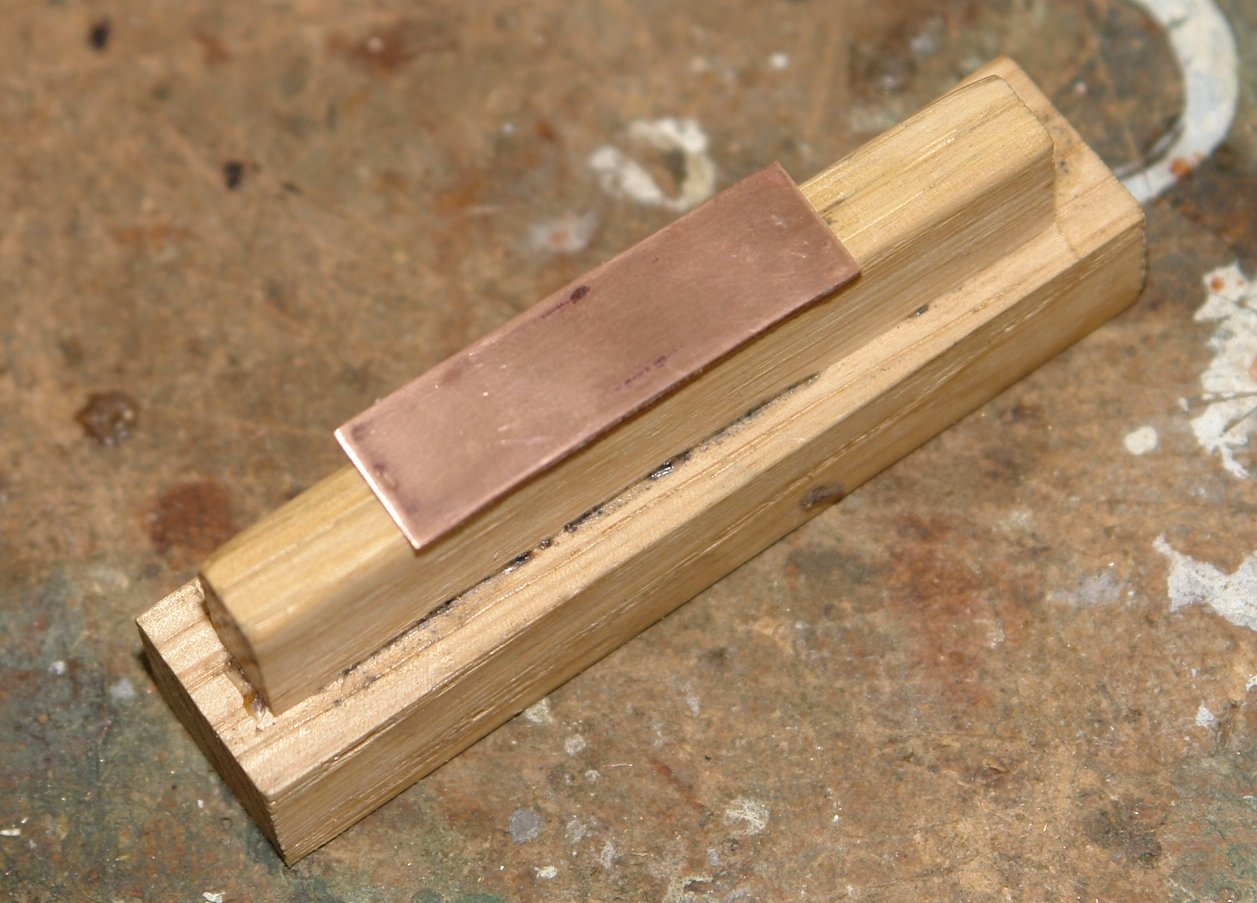
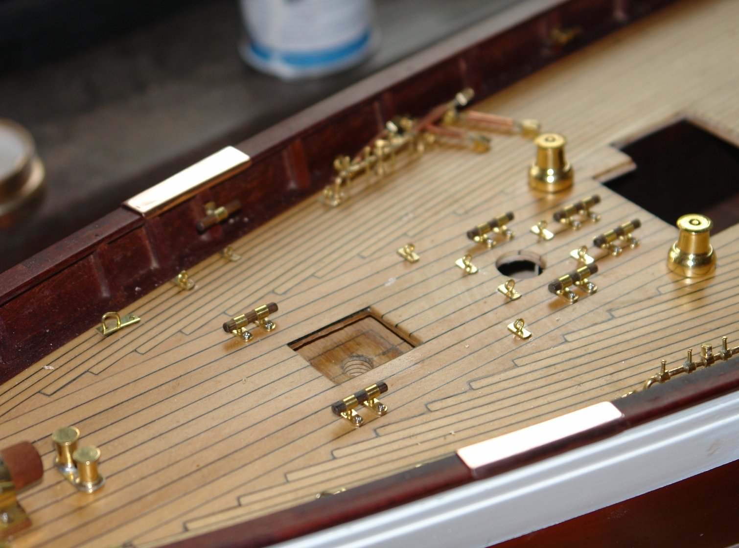
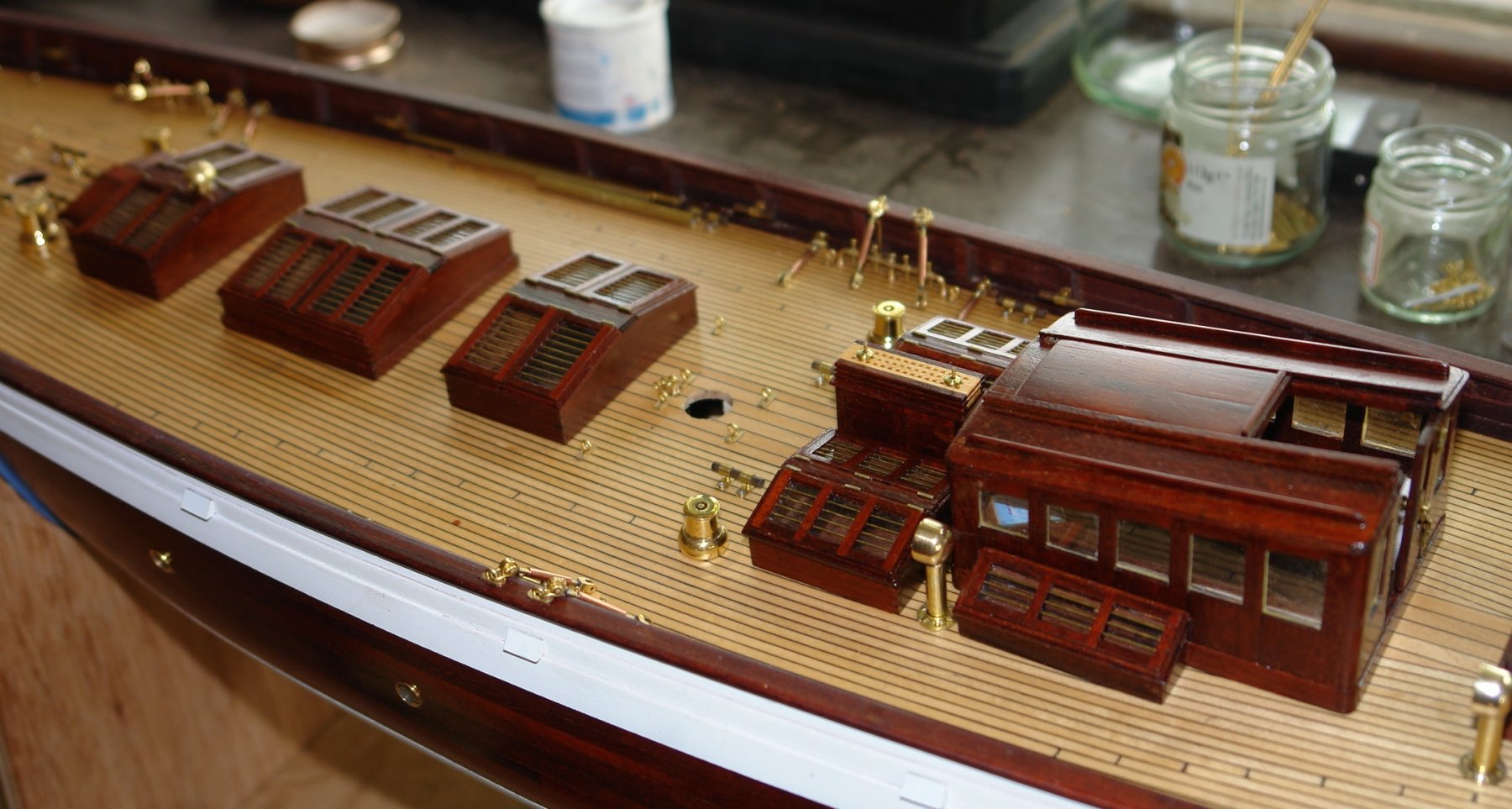
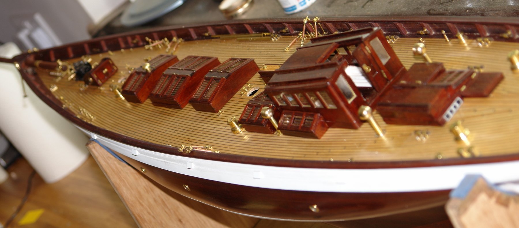
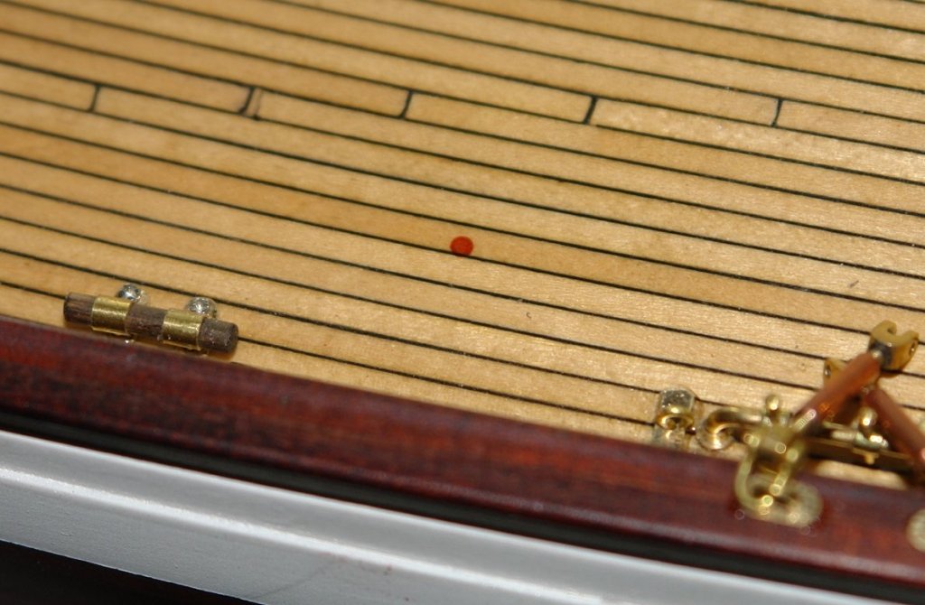
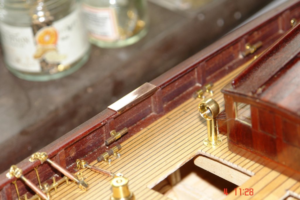
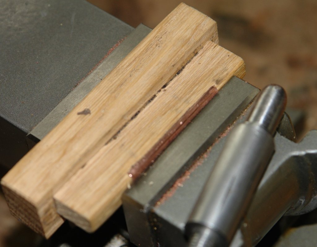
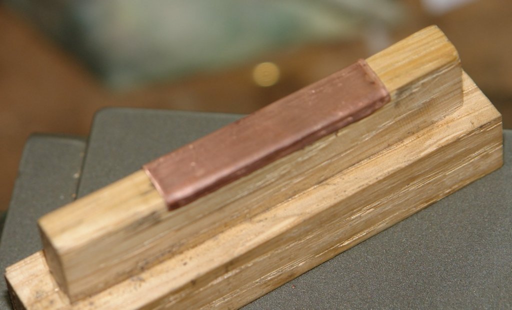
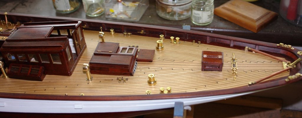
The bulwark capping rail has a number of features which I wanted to reproduce. the first of these are: Protective step plates at the top of the gangway steps:- Protective plates below the stowage position of the anchors:- In both instances the plate is copper with attached wear resisting brass strips. I drew a card pattern from the rail and used this to shape .015" copper sheet. The width was equal to the rail width plus the thickness to allow for the rolled over edge. The rail of course follows a gentle curve and so I made a former from oak on which I could shape the plates. The copper was heated to cherry red to soften it. it was then held in a vice, over the former, and the edge was pushed over using a rounded bar (in the photo) The formed plates were then polished and placed in position prior to gluing. I simulated the brass strips by using some etched sheet left over from previous build. And for now that is it as "THE SHIPYARD IS CLOSED"..............................Gone Sailing!!!!!!!!!!!!!!!!!!!!!!!! Swiftly, swiftly flew the ship, Yet she sailed softly too: Sweetly, sweetly blew the breeze— On me alone it blew. ……………………….S.T.C.


- 882 replies
-
- 11
-
-
John i keep looking in in the hope of finding sawdust. I presume research is going to be ongoing for a while?
-
Recommendations For A Good Milling Machine
KeithAug replied to Thistle17's topic in Modeling tools and Workshop Equipment
It isn't a big risk. Most distributors live or die by the the recommendations they get from customers. If they constantly shipped out equipment which was inaccurate, packed up after a few months, had dangerous sharp edges and or gearboxes full of swarf they would quickly go out of business. I think that choosing a good distributor is a reasonable way of reducing risk to an acceptable level. -
Recommendations For A Good Milling Machine
KeithAug replied to Thistle17's topic in Modeling tools and Workshop Equipment
The quality controls of the importer / distributor is of prime importance. Many importers have their own inspect and prepare facilities and do the necessary preparation work to ensure that the machine as delivered is ready to run condition. Additionally some importers have their own staff embedded in the manufacturing facilities to ensure that their equipment achieves their specifications and standards. it is important to choose a distributor who has a good reputation. My experience was that apart from removing protective grease I needed to do nothing other than switch it on. -
Recommendations For A Good Milling Machine
KeithAug replied to Thistle17's topic in Modeling tools and Workshop Equipment
I have to say that I don't share the negative experiences of Chinese lathes and mills. I have had mine for 5 years and have experienced none of the "cautionary" wear or accuracy issues suggested in previous posts. I regularly work to tolerances of a thousandth of an inch without any problems. I previously owned a Boxford lathe, a well respected UK manufacturer. It was replaced by the Chinese lathe at a 1/6th of the cost and I have to say I found it just as solidly made with the benefit of more features. It is true that the early Chinese machines which started to arrive in the west 20 years ago were of indifferent quality, however in more recent times they have got their act together and now produce good model engineering machines. -
Excellent Nils. I await the next one with interest.
- 2,625 replies
-
- 7
-
-
- kaiser wilhelm der grosse
- passenger steamer
- (and 1 more)
-
Recommendations For A Good Milling Machine
KeithAug replied to Thistle17's topic in Modeling tools and Workshop Equipment
Bill, I'm fairly sure the GO759 is yet another version of the machine I have and similar to the one I mentioned above. All made in the same Chinese factory and rebadged by distributors. I agree that this machine is a good compromise between size, power and usable capacity. Mine is badged Warco WM16, but if you look at the design it's virtually identical to the GO795. http://www.warco.co.uk/milling-machines/32-wm-16-variable-speed-milling-machine.html. -
Hi Shoosh It looks like you went to the races, did you win? Was your prospective husband looking for a handyman as a partner or was that the introductory bonus? Good luck with your build.
-
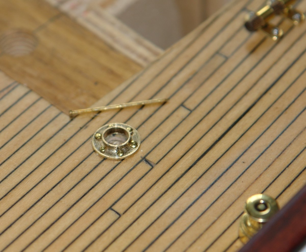
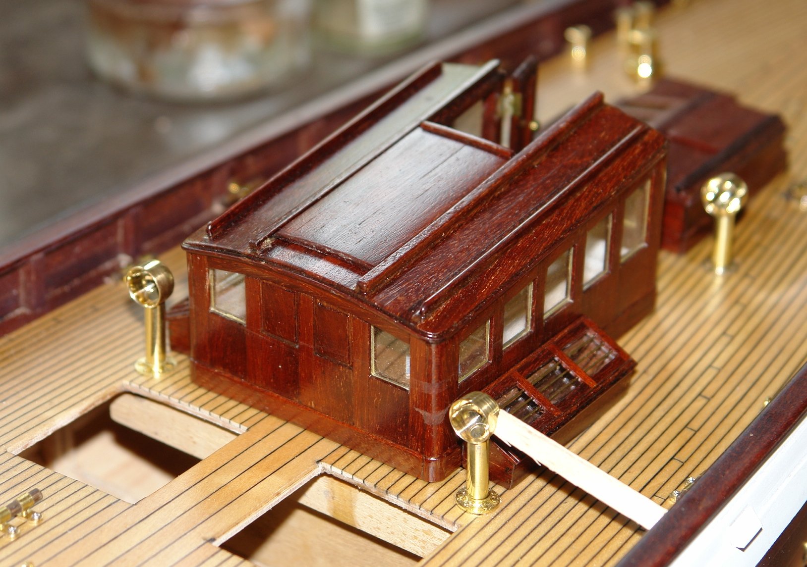
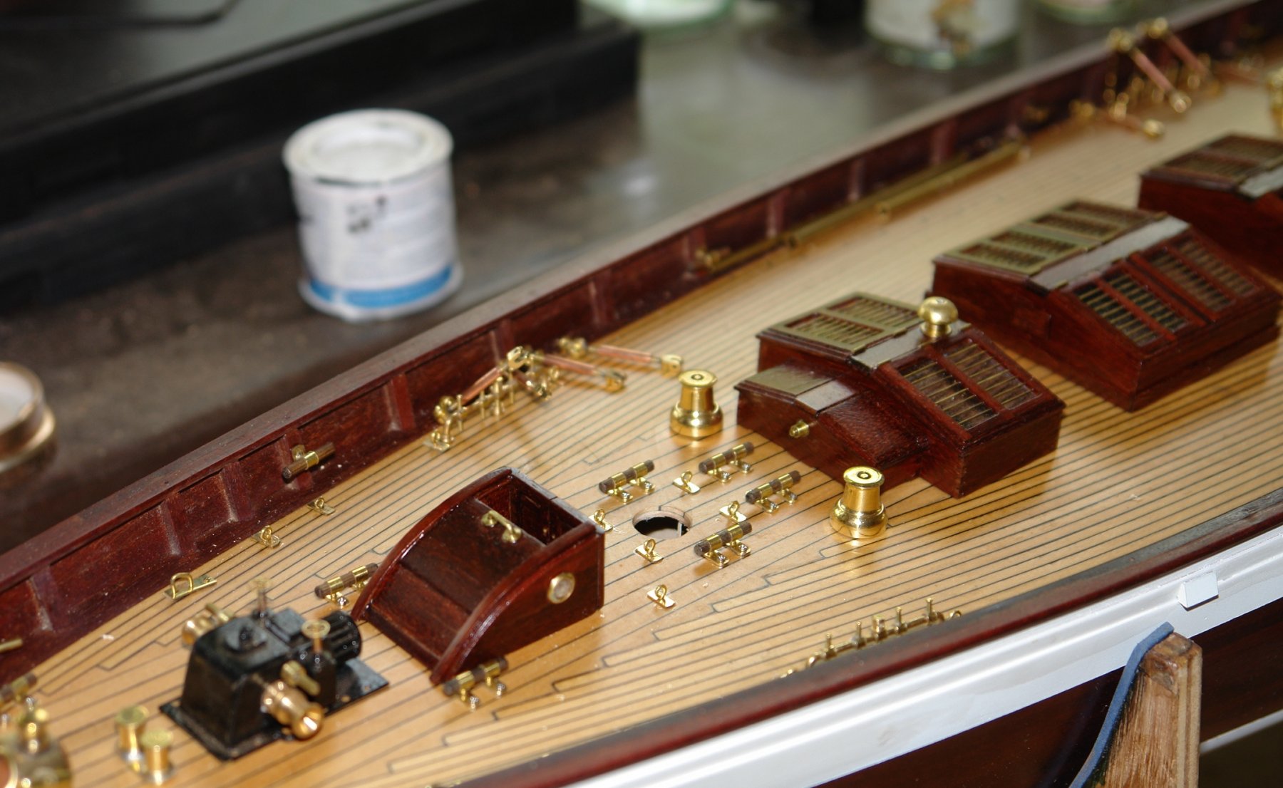
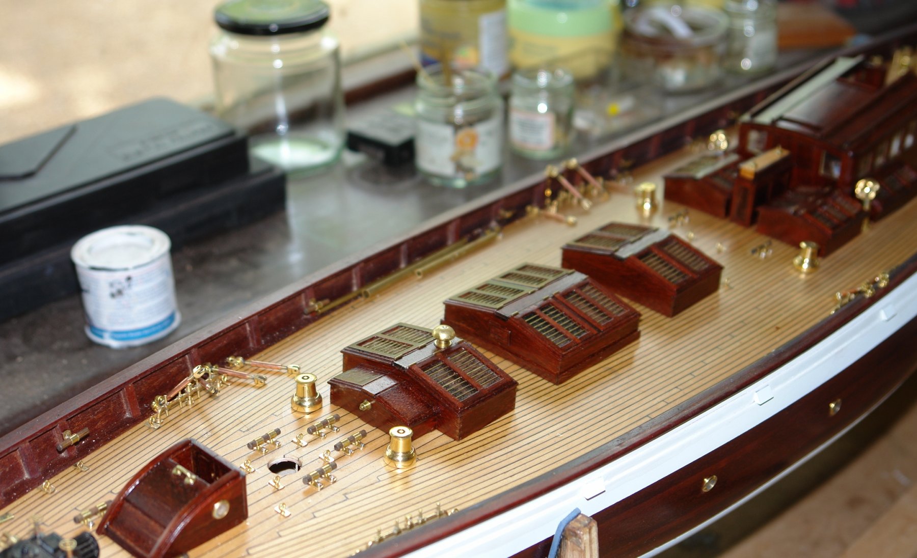
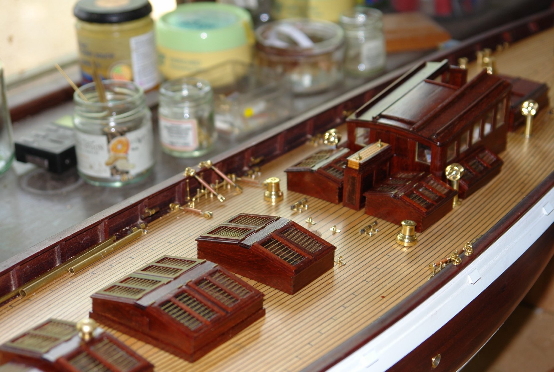
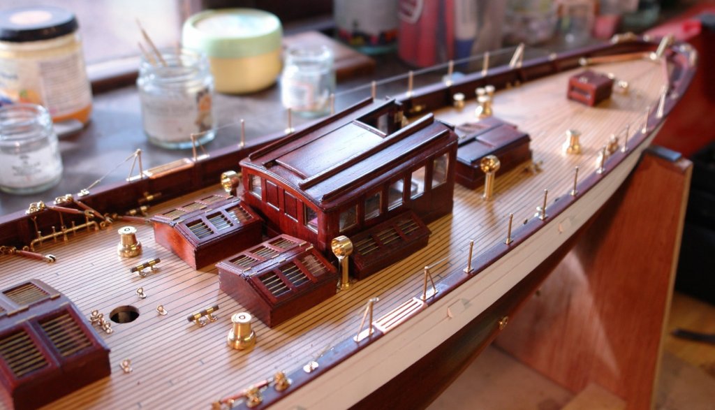
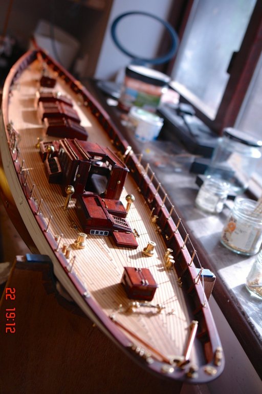
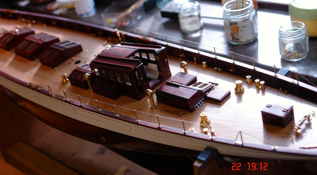
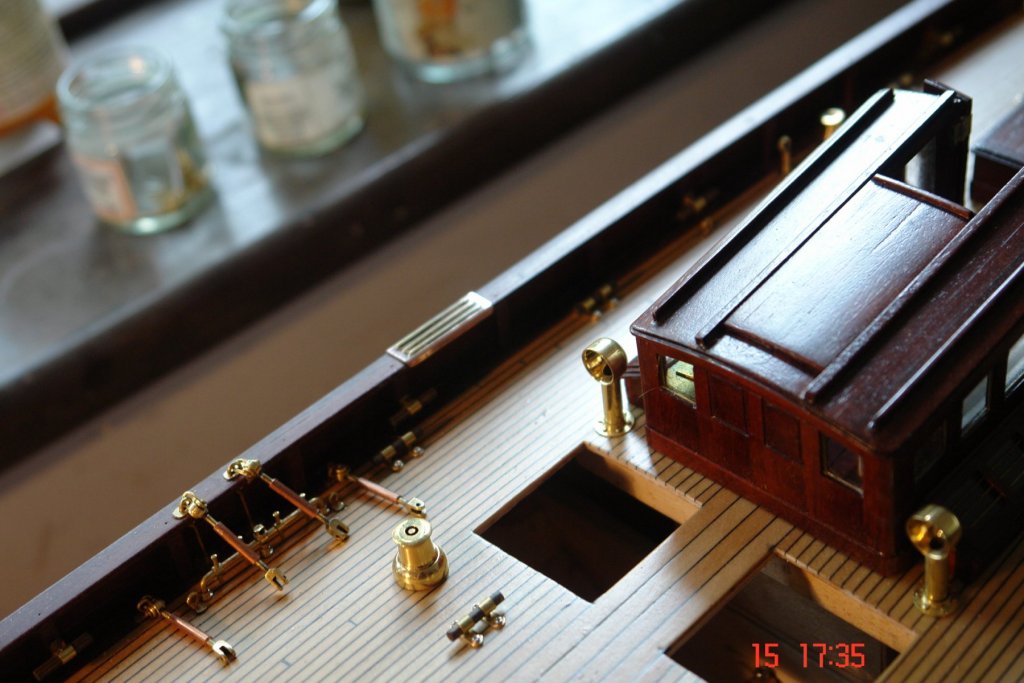
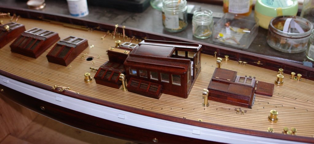
Julie, thank you for visiting and for your kind words. Greg - the pan is to install the pool table parallel with the floor. Every shot will be a winner if only I can get the balls to stay in place while a take the first shot. Richard - like the haggis I plan to grow one leg longer than the other - but also like the haggis I will have to remember never to turn round. Also thank you to all of you who have visited and left their "likes". The subject of yesterdays frustration were these flanges. They are only .070" thick and .375" diameter. They have rolling superpowers - I needed 4 but had to make 6. The other 2 are probably still rolling. They sit at the base of the cowl vents. The deck was drilled through the flanges and the vents were glued with 5 minute epoxy - to give me time to align them. The height was set with a split aluminium tube cut specifically of the job - you can see it in position on the port hand cowl. The alignment needed some assistance while the glue set - see the prop (courtesy of Starbucks) on the front port cowl. To celebrate the current stage of progress I put the deck lights etc, in place and took a few shots.


- 882 replies
-
- 15
-
-
Recommendations For A Good Milling Machine
KeithAug replied to Thistle17's topic in Modeling tools and Workshop Equipment
I have the UK equivalent one of these and I find it produces good accurate work. At 275lb it is quite heavy for a small machine but weight is an advantage with milling machines as it usually means improved stiffness and accuracy. It also has a good sized table which is a bonus. It is now 5 years old. I use it a lot and have fond it reliable (probably famous last words). http://www.machinetoolonline.com/files/PM_25MV-BD_9-2016_v4.pdf -
John / Richard - Thank you. Today was a little frustrating but out of the frustration came a plan. When I next remodel the workshop I have decided to lay the floor to falls. I think a compound slope of 45 degrees would be about right, with the low point in one corner. Set in the corner will be a sump lined with a closely fitting bucket. I realise that this will present a few problems with the legs of workbench and chair, and of course i'd have to invest in some extra long levelling screws for the lathe and mill. These minor problems however pale into insignificance when considering the benefits of such an arrangement. The time saved in looking for dropped components and tools would be immeasurable!!!!!!!!