Supplies of the Ship Modeler's Handbook are running out. Get your copy NOW before they are gone! Click here to order
×
MORE HANDBOOKS ARE ON THEIR WAY! We will let you know when they get here.
×


KeithAug
-
Posts
3,867 -
Joined
-
Last visited
Content Type
Profiles
Forums
Gallery
Events
Everything posted by KeithAug
-
 Lovely little boat Gary. looking forward to it.
 -
Denis - I bought an old mahogany table which had worm in some of the soft wood framework. It proved to be low cost and very good quality wood. You might want to consider getting some old mahogany as it is much better quality than the modern stuff.
-
What wood are you using for planking Dennis? Are you double planking?
-
Eberhard - I am surprised they came out as well as they did with solid wire, but as I said I only noticed it in the one close up shot. I find small electrical motors from broken toys are a good source of very thin wire.
-
I wonder if it is a line for an anchor marker buoy. Attached to the anchor with a buoy on the deck. Drop the anchor and throw the buoy overboard so the buoy marks the position of the anchor. This lets other vessels know where the anchor is so they are not inclined to drop there hooks on top of it.
- 454 replies
-
- 2
-

-
- Union Steamship Company
- Stepcraft 840
- (and 3 more)
-
The suck it and see approach is also valid, you will probably find that just "doing it" produces fully acceptable results.
-
Nice detail Eberhard. In the second to last photo the stays from the mast to the deck abreast the smoke stack seem to have some curvature but this isn't obvious in the other images. Is it a photographic effect?
-
Sorry Andy - memory failed. Mac's don't seem to have that capability, unless they hid it somewhere that wasn't obvious.
-
Gary - Is that a Mac print programme?
-
Grant - I had a look round the local print service companies which seemed to offer prints uf up to A0 in size (smaller than I need). They were not exactly cheap. I think I can manage the accuracy issue and at least if i print at home I can avoid a car journey. Yorkshiremen are noted for being careful with their cash and my wife says I am an extreme example. Her lifetime mission has been to compensate for my behavior and in that she has proved to be a master!
-
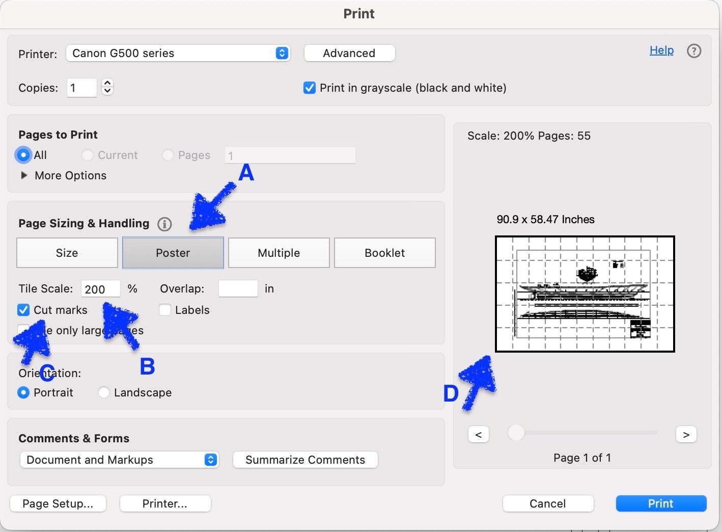
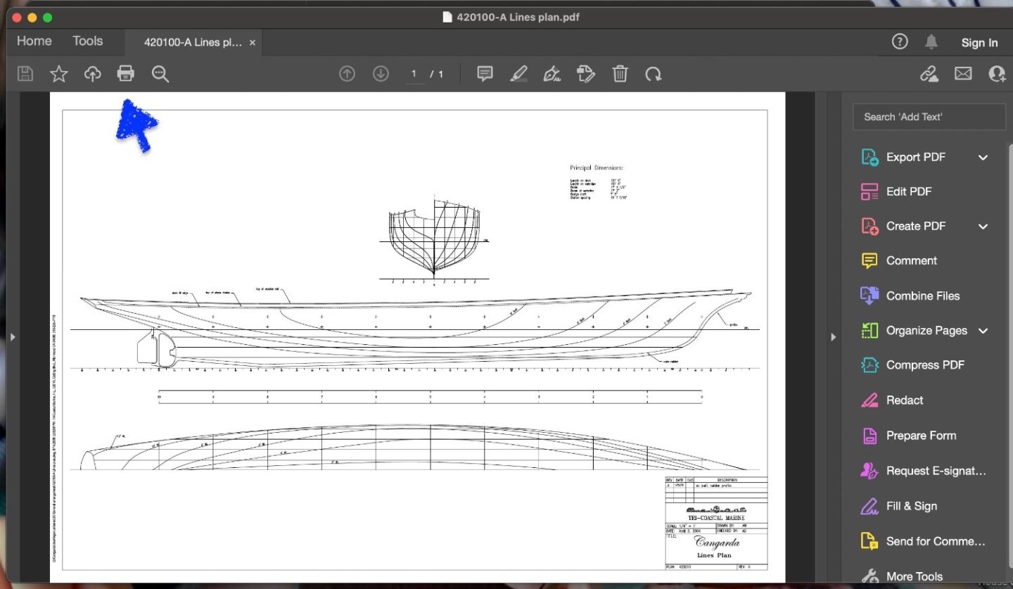
I spent a few hours of today working out how to print the hull lines at 1:24 scale. The lines PDF file supplied by Tri Coastal Marine was drawn at 1/4" = 1' (1:48) so I needed to print them out at 200% scale. Both the standard and Safari print programmes on the Mac seem to have limitations on how they print scale copies across multiple sheets so I had a look for an alternative. A bit of research led me to Adobe Reader (free download) and this proved to be much more user friendly. The lines drawing was imported into Adobe reader in PDF format. This opens up the following screen. Clicking the print icon then pulls up the following screen: Selecting the "Poster" option (A) enables printing across multiple sheets. Selecting the scale (B) allows the PDF to be printed at the desired size and also defines the number of pages that the image will be printed over. Selecting cut marks (C) instructs the printer to print alignment marks on the printed sheets. This significantly eases the assembly of the printed sheets into a composite picture. The image at point "D" adjusts automatically to show how the image will be printed across a number of sheets. In my case i was using and A4 printer and the image was printed over 55 sheets. Fortunately a few months ago I invested in a "Big Tank" inkject picture so printer costs were not really a consideration. I used the same procedure for printing out the other 2 PDF's provided by Tri Coastal Marine.
-
Roger - For a while I worked in the Chemical Plant Design Office of British Nuclear Fuels (Nuclear Reprocessing). Of necessity at times I got involved in the design of reprocessing plant pressure vessels (and pipework). Because of their often unique shapes and restricted geometries the pressure vessel code rules were frequently inapplicable. For safety assurance reasons we often had to design the vessels from scratch using finite element analysis. For the services pipework we did however use ASME codes and their British Standard equivalents. My early career was spent with Rolls Royce at Derby (1969 to 1978), partly in the aero engine design offices. The nature of the materials, the design loadings and extreme environments made code based design rules inapplicable. I agree however that in many instances (including shipping) the code based design approach has a lot of merit. The watch out of course is to avoid extrapolating the code to cover circumstances beyond its intended use - as was the case with the Heathrow runway light.
-
Roger, Interesting - another example of code based engineering. I once had to investigate an incident with a plane that landed at Kansai International Airport with a 2kg Heathrow landing light retaining ring embedded in its hull (but fortunately not the pressure hull). Kansai were not impressed! The retaining bolts for the ring had all sheared off allowing it to become loose and presumably it had been flipped out of its seating by the nose wheel on take off. During the investigation it became clear that the code had first been formulated some 50 years previously and the calculations within it were based on the wheel loadings of a DC-3. The wheel loadings of Boeing 747's are somewhat higher than those of a Douglas DC-3's. Some codes now allow for engineering analysis in lieu of historic precedent but I accept this isn't always the case. I wonder when the 1ft rule was first formulated and what specific geometries and loading conditions it was designed to accommodate. However "The Rules is the Rules" as they say. At least I now know how wide to make Cangarda's porthole strake = porthole diameter plus 2 feet.
-
Thank you Roger. I had picked up some of the detail but not all of it. I don’t have the 2010 paper so I will look it out. I have some of the build photos from her restoration so I was aware of the welding and fairing. As I mentioned earlier I was a bit surprised to see that thicker plating had been used on strake that encompasses the portholes meaning that the hull isn’t entirely smooth, so this should add a bit of modelling interest. I think there are still a couple of riveted hull steam powered vessels operating sight seeing services in the UK.
-
Impressive metalwork, winches and booms. I would have loved to have seen more of your techniques.
-
Yes Bob the language barrier strikes again: Brightwork also known historically as "bright work" refers to the exposed and varnished wood or metal work of a boat.[1] The metal is usually brass or bronze that is kept polished, or stainless steel, which requires less maintenance.[2]
-
Early post restoration photos appear to feature what i would recognise as a modern representation of a traditional block.
-
They are great Rick. I have spent most of this evening studying and organising the photos, quite an enjoyable evening, particularly when I suddenly realise what an obscure image is ( eg the steam whistle hiding in the canvas). Could you please pass on my sincerest thanks to everyone who has facilitated your visit. A lot of other MSW members appear to be enjoying going through the images so that’s another accolade for your efforts. Have a good day.
-
That's very interesting Roger. The one obvious anachronism in this approach is the fitting of the stabilisers. To me they look quite out of place on this style of hull. Bob. The brass isn't in a great state which in my book is a crew duty. I don't know whether Cangarda was built with traditional wooden blocks but agree stainless steel and plastic look out of place.
-
Keith - She is an old lady making the most of her golden years. I hope you don't talk about the Admiral having gone to seed! Also don't tell her about the restoration costs being conditional on continuing love! I am planning to model her as freshly restored because that is how I like to imagine her - Cangarda that is!
-
Thank you Rick - some great detail there. The deck detailing around the deck houses plus much of the other stuff will prove extremely useful. The deck is remarkably uncluttered compared with that of Germainia. During the course of the build I am almost certainly going to find myself coming back to you to ask where is this or that bit. I hope you are in good health and planning to be around for a while? Some of the background reading confirms that the original panel has been retained as a museum feature. I guess the roof of the aft cabin is pretty clean. It doesn't have guard rails so obviously nothing up there requires routine access. Very nice winch detail but now I am going to have to figure out how I depict graded hoses. What do you want to do about the remaining photo's - (or have you sent them all?). It's fine by me if you just keep posting them here if you have any more to send? Once again thank you for all your help.
-
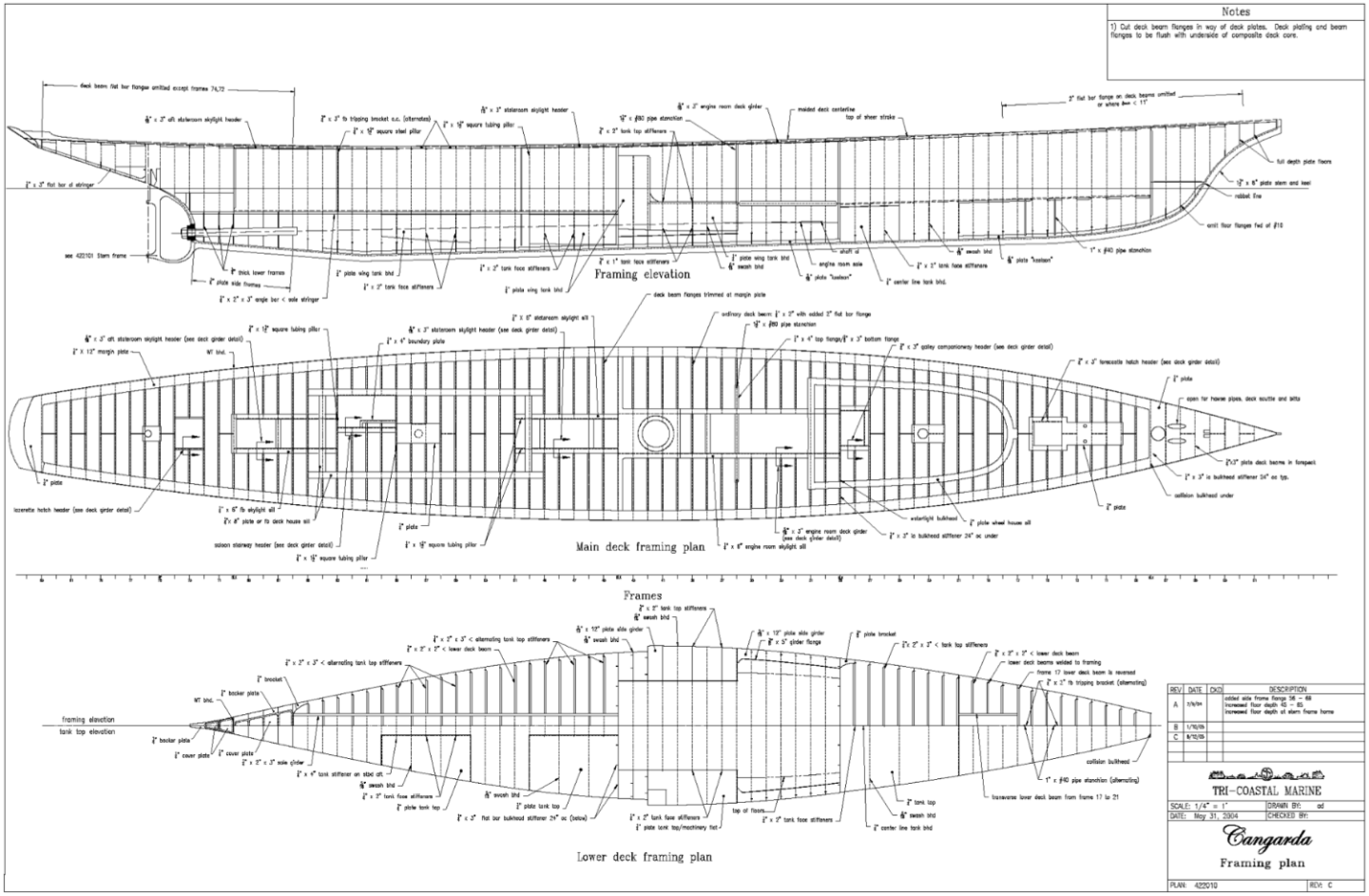
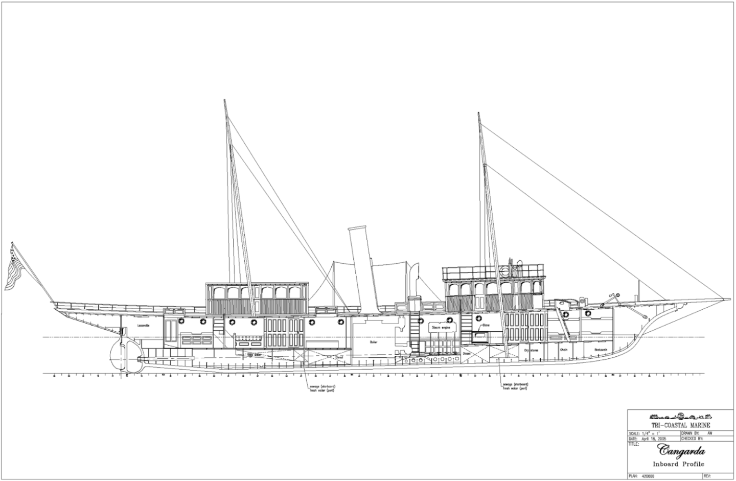
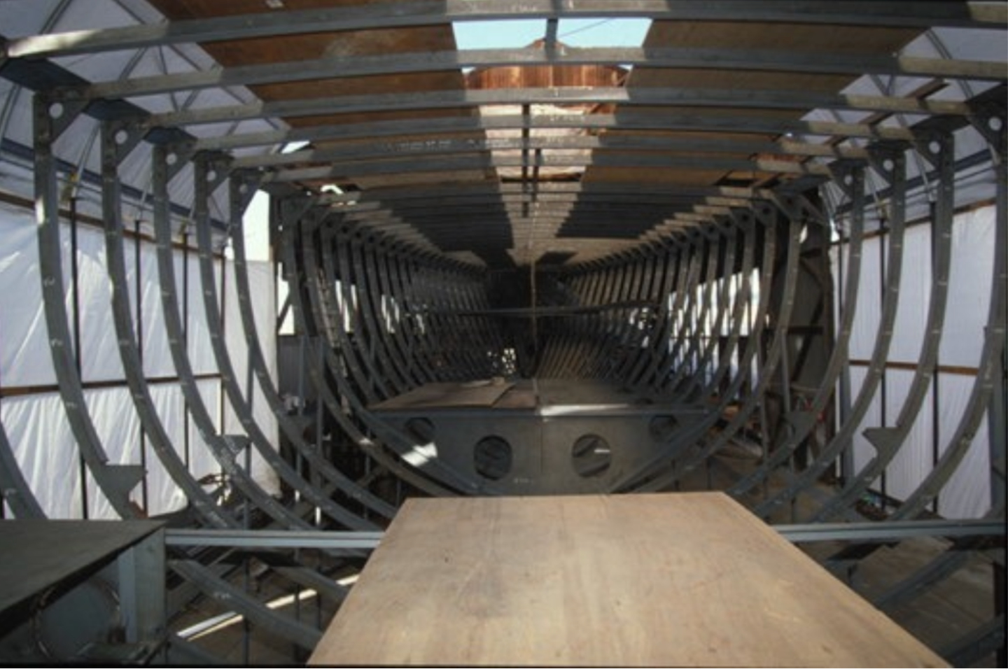
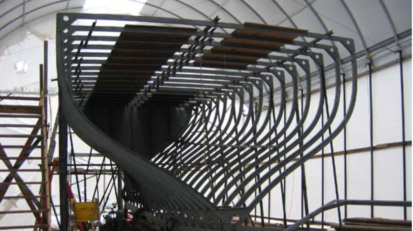
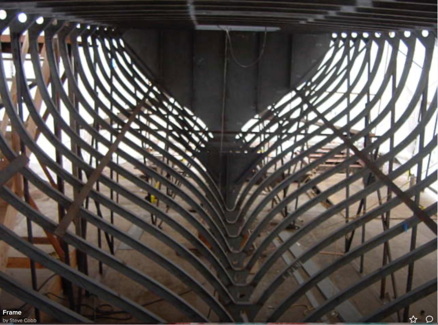
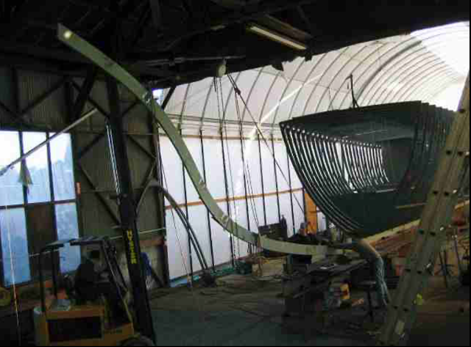
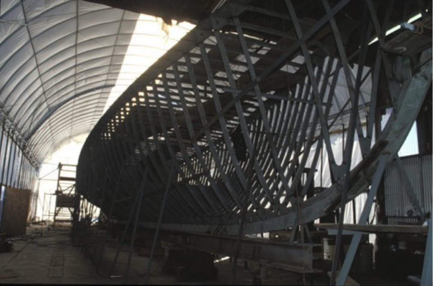
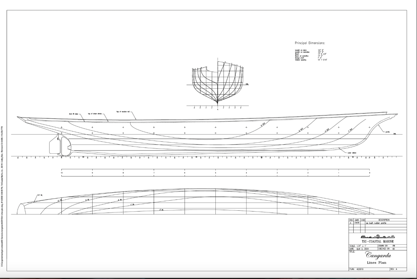
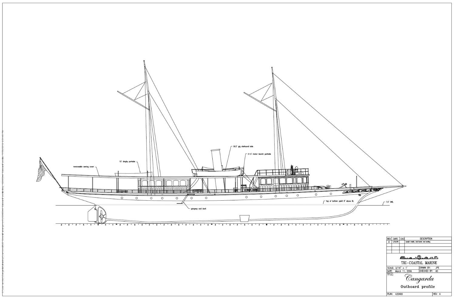
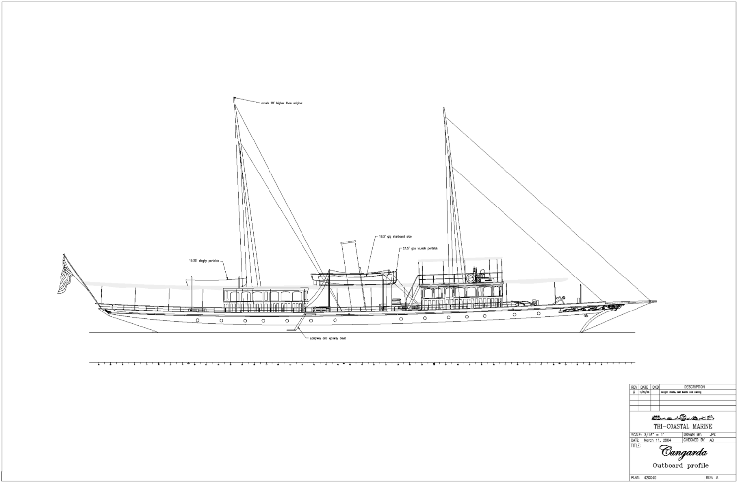
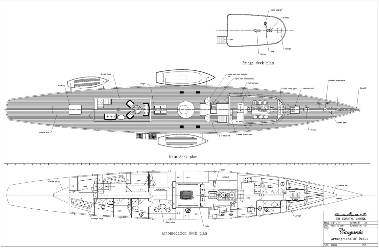
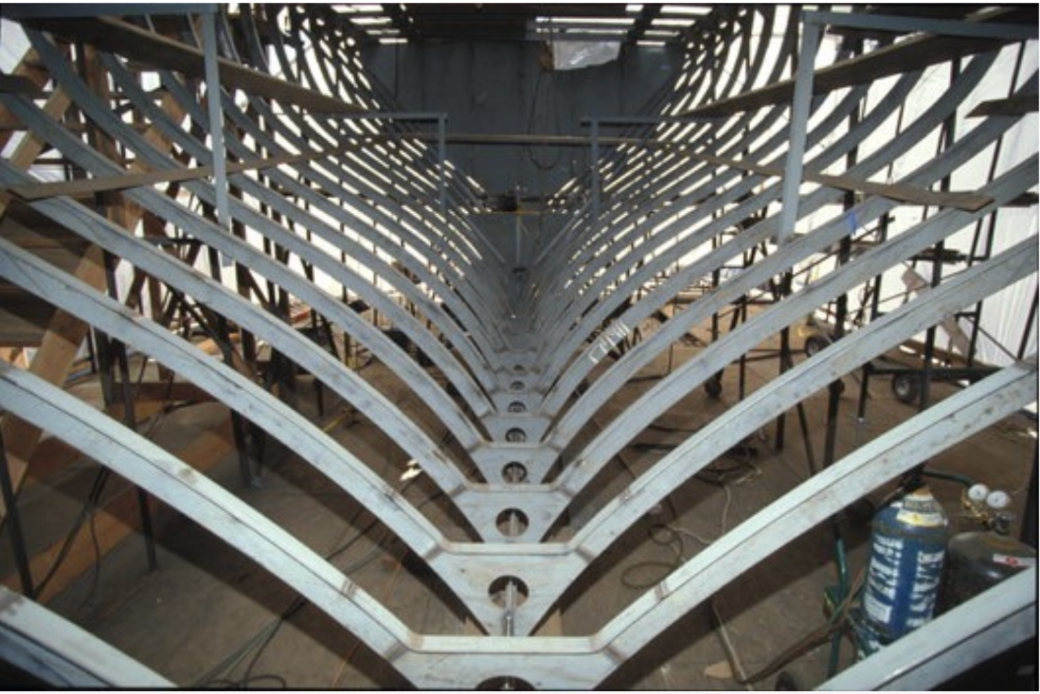
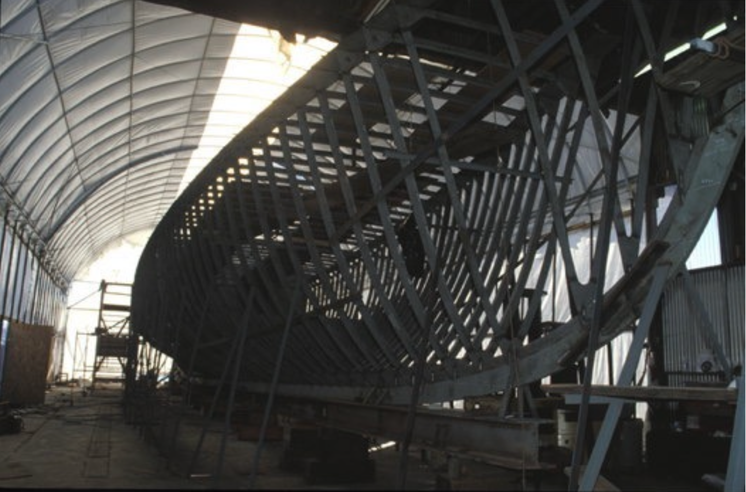
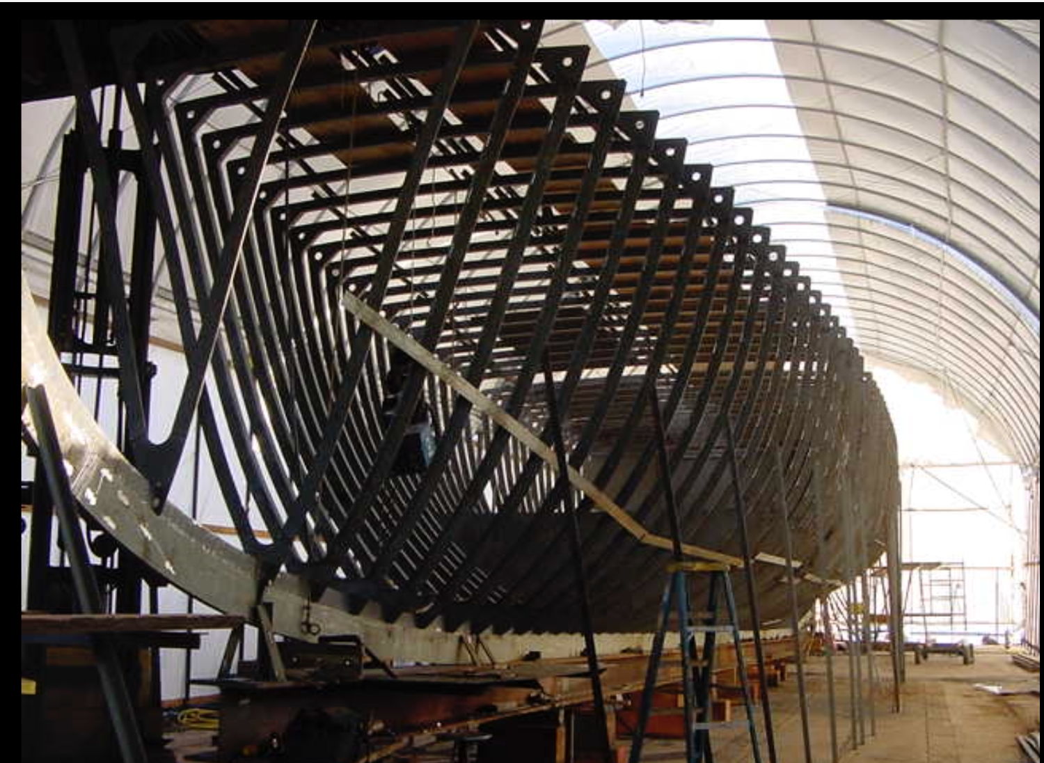
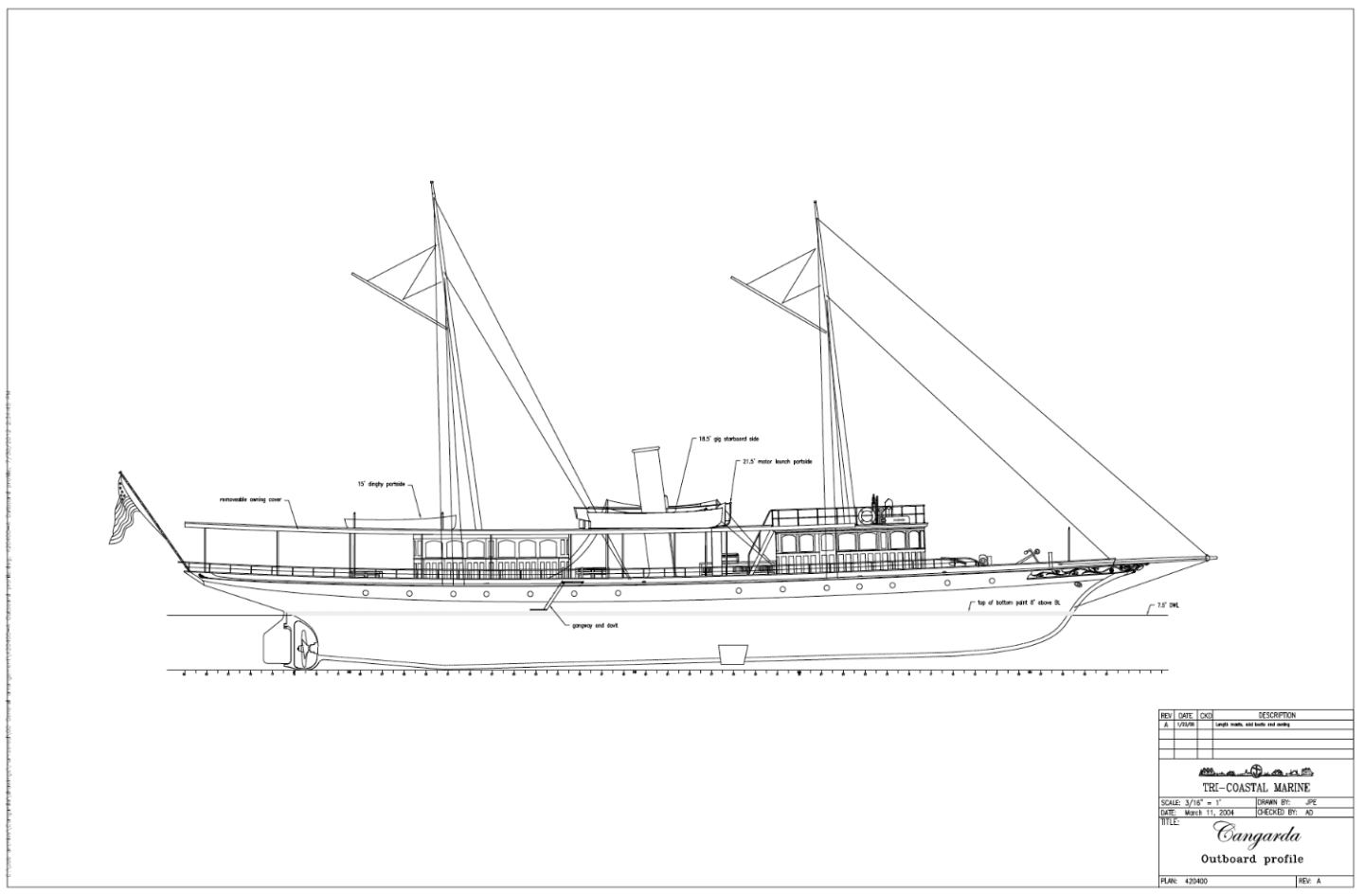
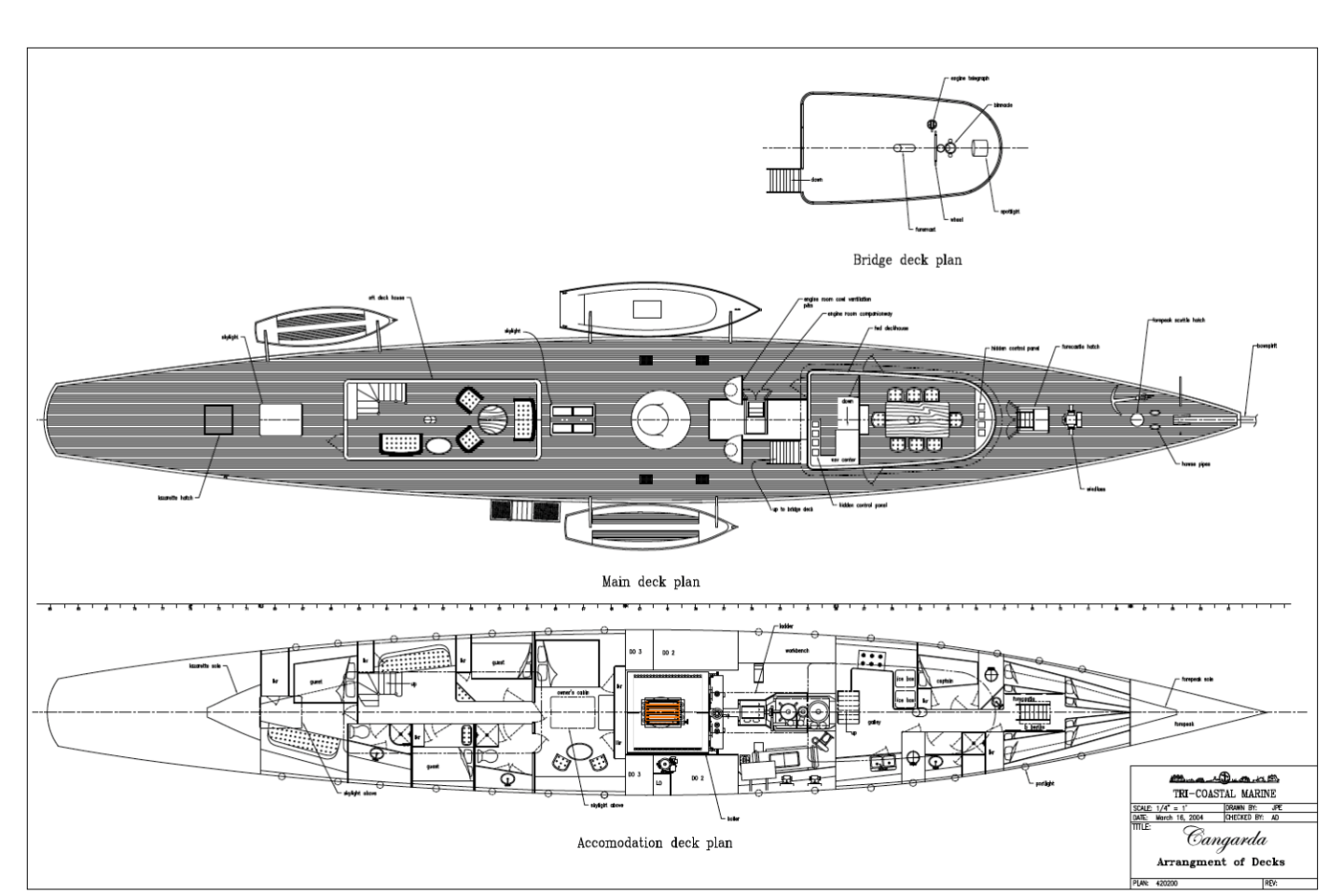
So I had better make a start but firstly a big thank you to all of you who have engaged with this project thus far. I will try to be as enthusiastic as you all seem to be. I have been collecting photographs and looking for plans of Cangarda on the net for about 8 months. It is fairly normal to find web photographs of restored classic yachts. Typically they are photographed in anchorages and photographs are also taken when they are sold or chartered. Unfortunately these photos are generally less than ideal for the typical modeller. For a start, much of the charter photography focuses on broad external overviews complemented by extensive detailed shots of the internal accommodation. The camera rarely points down at all those interesting deck fittings or up to the heavens where all that fascinating rigging resides. Shots taken at anchorage (or in transit) are also generally less than ideal. They tend to be taken from too far away to get the detail and of course deck detail is generally obscured by the viewing angle. Sometimes as in Cangarda's case photographs of the restoration are available and these can be a useful resource. So far as plans are concerned, in Cangarda's case I was somewhat fortunate. A paper to The Classic Yacht Symposium 2006 covering the early restoration of Cangarda contained 4 useful plans as follows:- These plans while containing a lot of detail were contained within a PDF document and I struggled to find a way of extracting them while keeping the detail. The images posted above are screen shots and of course when these are blown up they pixelate and produce saw tooth line edges which aren't very useful. Notably the plan information did not contain hull lines and at this stage this was the most significant obstacle to attempting a successful model build. What did give me some optimism was that I had found a lot of on line photographs of the hull fabrication. With these I had started to get a bit optimistic that I could use the available plans (above) with the general frame shapes to make a reasonable representation of the hull form. Interpreting the frames from the camera angle distorted images to generate the frame sections wasn't going to be easy but hey i was willing to give it a go. I am always a bit reluctant to put upon people and this was probably the reason that I only recently contacted Jeff Rutherford whose boatyard undertook the restoration of Cangarda. I couldn't have been more delighted with his response. Jeff confirmed that there were no lines originally and that the designer drew the profile of the bow and stern and the yard filled in the rest. The hull was then digitally scanned and the lines were retrospectively generated. Jeff put me in touch touch with Andy Davis of Tri Coastal Marine who supplied the "precious" hull lines drawing in PDF format together with a bonus reproduction of two of the plans from the 2006 paper. The lines at this stage are not sufficiently detailed for modelling having only 11 abeam sections (5.5" spacing at 1:24 scale). The hull of Cangarda is constructed on 86 frames all equally spaced at 18" full size or 3/4" at 1:24 scale. Only one of the cross sectional hull lines aligns with a frame (frame 75 at the ruder post) with all the others being set off from the frames by varying distances. I want the frames on the model to align with actual frames (I learned this lesson on Germania see note1 below) and so I need to do a lot of draughting to generate the frame drawings. I have decided that I can get away with 43 frames for modelling purposes giving a frame spacing of 1.5". I guess it is now time to get down to a few weeks of tedious draughting to generate the 43 frame drawings. Note 1 - On Germania I didnt align the frames with the actual frame positions which became a problem when cutting the port holes (which invariably sit between frames) - some of which sat half on and half off the plywood frames - making for some very tricky drilling.