Supplies of the Ship Modeler's Handbook are running out. Get your copy NOW before they are gone! Click here to order
×
MORE HANDBOOKS ARE ON THEIR WAY! We will let you know when they get here.
×


KeithAug
-
Posts
3,867 -
Joined
-
Last visited
Content Type
Profiles
Forums
Gallery
Events
Everything posted by KeithAug
-
 Yes it's quite amazing isn't it Phil. I felt sight discomfort at times during the operation but no real pain. I guess the eyes don't have many nerves to register the pain. Before the operation my biggest worry was the thought of seeing the scalpel heading toward my eye. No one told me that the operating light would be so strong that I wouldn't see any of the surgical procedure / instruments. All a piece of cake really.
 -
Eric - I had assumed it was intentional. My guess is that many of these working boats would have been built quite roughly. A high quality finish might detract from the authenticity of the finished model.
-
HMCSS Victoria 1855 by BANYAN - 1:72
KeithAug replied to BANYAN's topic in - Build logs for subjects built 1851 - 1900
Oh dear Pat - I hope it wasn't too bad and recovery was rapid. I guess we will all get it at some time. Over here we seem to have settled into annual autumn vaccinations. Flue one arm covid the other.- 993 replies
-
- 3
-

-
- gun dispatch vessel
- victoria
- (and 2 more)
-
Richard - anything involving dust - mostly housework.😀 Thank you all for the good wished. I am going to create the manufacturing drawings for Cangarda's screw, rudder and rudder post today. At least that will make me feel a little useful.
-
Yes Brian - Cataract surgery is fantastic. I'm glad to hear it worked so well for you. I'm looking forward to getting the other side done.
-
Lovely draughting work Andy. Frame 3 is quite revealing of the "fineness" of the bow.
- 174 replies
-
- 2
-
-
- Vigilance
- Sailing Trawler
- (and 1 more)
-
So that is one eye done. It turns out that the world is incredibly blue and bright. I have spent the last few hours turning the contrast and brightness down on all the TV, computer and phone screens. If I look through only my old eye all the blues have a distinctly yellow appearance a cross between colour and sepia tone photographs, while my new eye delivers such strong colour contrast its almost like a laser beam bing fired into my retina. Closing and opening each eye in turn produces incredibly different images. The focus isn't all that precise at the moment but I am told this will come over the next couple of days. So far so good. P.S i haven't looked in the mirror yet or studied the wife. The dog however is looking very cute. Eberhard - its much better than any new glasses i have ever had. Gary - I am shattered. Ras - Thank you for following. I have to agree with your sentiments.
-
Clearly eyes not working that well - i intended putting the update in Cangarda - i will copy across. Thank you Keith / Eberhard for good wishes.
-
So that is one eye done. It turns out that the world is incredibly blue and bright. I have spent the last few hours turning the contrast and brightness down on all the TV, computer and phone screens. If I look through only my old eye all the blues have a distinctly yellow appearance a cross between colour and sepia tone photographs, while my new eye delivers such strong colour contrast its almost like a laser beam bing fired into my retina. Closing and opening each eye in turn produces incredibly different images. The focus isn't all that precise at the moment but I am told this will come over the next couple of days. So far so good. P.S i haven't looked in the mirror yet or studied the wife. The dog however is looking very cute.
-
Tom - if you are referring to the keel slots I think I may cut them on the Byrnes saw not on the mill as i did with Altair. The slots will be much narrower on Cangarda. 1/8" on Cangarda, 1/4" on Altair.
-
Nils - the scroll saw is powered. I'm not dedicated enough to do 41 frames by hand.
-
Don't buy bathroom scales. About 40 years ago I bought some for Christmas and the divorce proceedings went a long way before she forgave me! Every time I go out to buy her a present she reminds me of the experience.
-
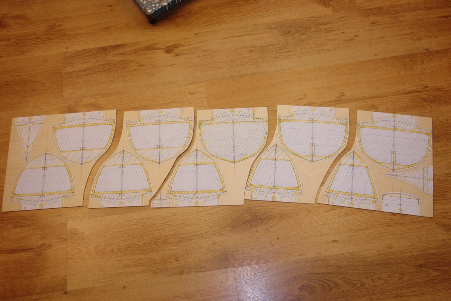
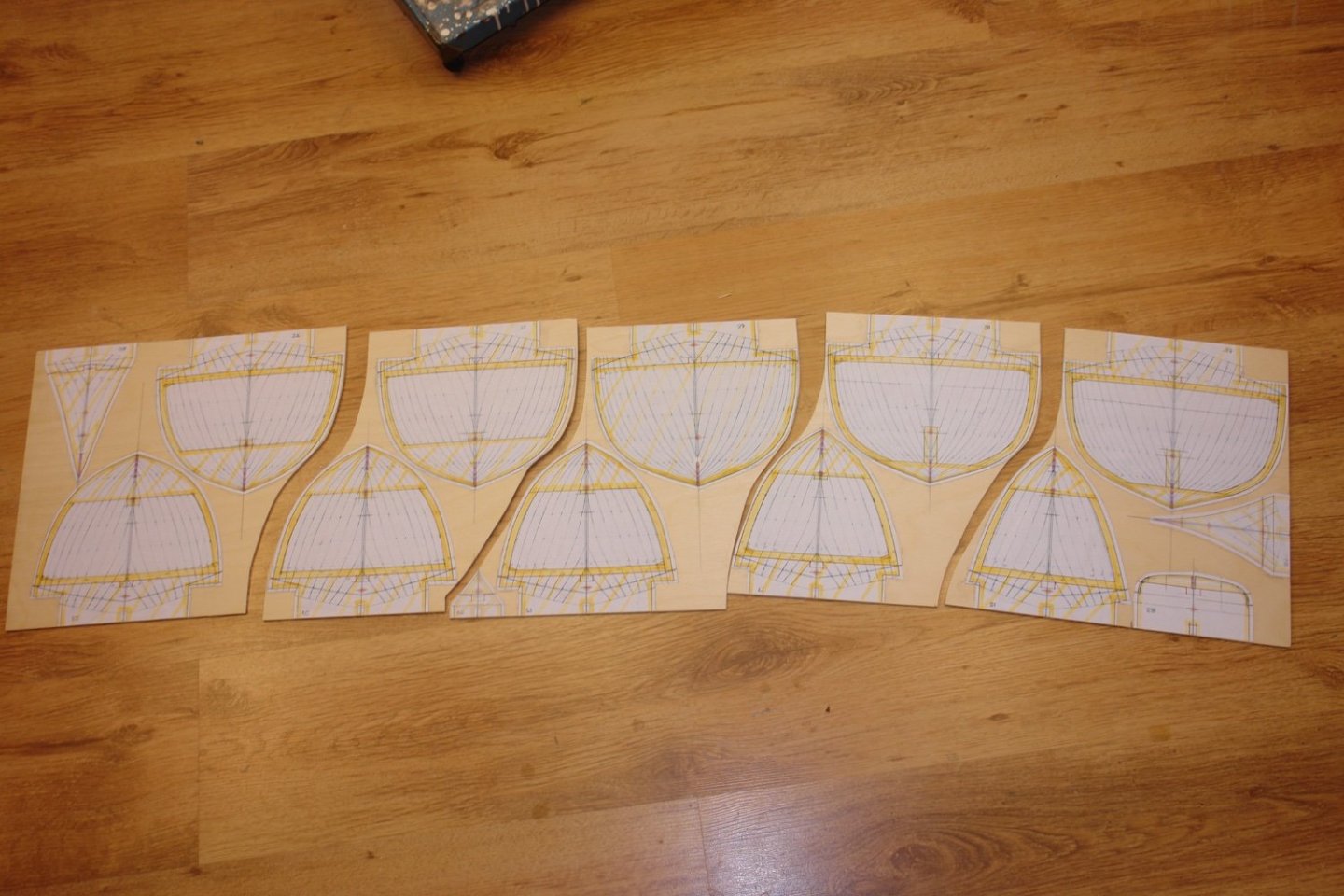
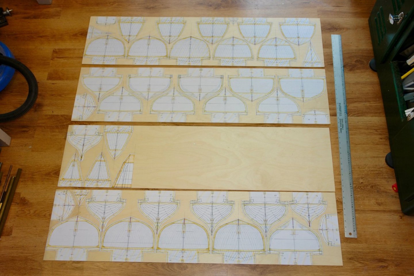
Thank you all for taking an interest in my minor operation. I decided to make hay while the sun shines so I cut some wood I printed and cut out the frame templates and then glued them to the 1/8" birch ply sheets. I glue them using Pritt Stick which I find adequately secures the paper while making removal acceptably easy. The sheets are 12" x 48". I did a few arrangements to try and minimise the wastage. There are 41 frames plus the stern keel piece. I didn't print the bow keel piece because my short term memory failed. I then separated all the frames using the hand held jig saw. So now I have 42 pieces of wood ready for the scroll saw. I get to use the scroll saw in anger about every 4 years and I have to go through the learning curve each time. It isn't worth making a start however because all the lines a fuzzy. Hopefully they will become much clearer in due course. Tomorrow my daughter is taking me Christmas shopping to ensure that Santa has an adequate pile my wife. Hopefully I will buy the right things and as a result I will make it through to the New Year without too much grief.
-
Michael - unfortunately not possible, banned from any activities which involve dust or spray - Including showering! May need to spend a lot of time in the playroom.
-
Yes a miniature miracle indeed. Very impressive.
-
The lovely work continues Richard. I didn't quite understand - are you printing the scroll work on the bow?
-
Just catching up Gary. I hope you are keeping well. The end of the year is fast approaching so hopefully the shipyard will soon get back into full swing.
-
Nils - I find that the problem with scratch builds is that everyone is an experiment. I have often thought that it would-be better to build each model twice and eliminate all the inaccuacies that inevitably occur in the first version - unfortunately life is too short.
-
Thank you all for the good wishes re my eyes. The first one is bing replaced on Monday so I am trying to make a bit of progress before I am banned from the workshop. They do one eye then the other after 4 weeks presumably to make sure the first one works before attempting the second. Anyway I have to avoid housework / shedwork for 2 weeks after each replacement. My wife doesn't trust me to be sensible so I expect to be under close supervision for a while.
-
The crew heads are excellent. For clarity I am referring to the heads that sit upon the bodies not the bodies that sit on the heads.
-
Great Model George. I spent an enjoyable afternoon visiting her about 30 years ago. Unfortunately I now live at the other end of the country. I remember the huge transverse beams designed to take the pressure loads from the ice pack. They crossed the hull in the accommodation areas at a most inconvenient height. She is well worth a visit but Rockville is more than an afternoon trip away. Good luck with the build.
-
Thanks again Valeriy. I sort of assumed you might be using different melting point solders and heat sinks - but your method is much easier.
-
Valeriy - thanks for the advice.
-
Sorry Valeriy I should have been clearer. I was referring to the bulwark not the deck plates. Eberhard I agree but plasticard is always an option. Also I have found paint finishes on brass to be a bit problematic as in my experience the brsss doesn't take the paint evenly and when dry flaking tends to be a problem. It may be that I haven't prepared the surface correctly.
-
Valeriy - As Eberhard says - I must do more brass work to develop my skills. Very inspiring. It would be good if you were able to supply more detail on your build / soldering sequence. I'm interested in how you make the later joints without unsoldering the earlier work? Also it would be interesting to know why you chose brass for the deck planks rather than something else e.g. very thin birch ply or even card?