Supplies of the Ship Modeler's Handbook are running out. Get your copy NOW before they are gone! Click here to order
×
MORE HANDBOOKS ARE ON THEIR WAY! We will let you know when they get here.
×


KeithAug
-
Posts
3,867 -
Joined
-
Last visited
Content Type
Profiles
Forums
Gallery
Events
Everything posted by KeithAug
-
 Hull looking good - workbench may take some time to find😀.
 -
Wonderful project Andy. It will be a pleasure to watch the model come to life.
- 174 replies
-
- 4
-

-
- Vigilance
- Sailing Trawler
- (and 1 more)
-
Nice work on planking Hakan. I see your summer break turned out to be shorter than mine. I only recently returned to the workshop having missed the autumn temperature sweet spot. It's now pretty cold which should be an incentive to work harder. Hope you are keeping well.
-
An unusual and interesting project. I hope she has a longer life than the original. The giant seagull attack wasn't mentioned in the film!!!!
-
Nice project Richard. Pity about the financial machinations I think you need a fairly punitive break clause in future contracts.
-
Thank you all for your congratulations. Its now day 12 and todays report from the mother is he has made an amazing discovery "humins is nocturnal". He had been sleeping very well.
-
Andy - yes I noticed that. Maybe a Naval career. His big sister has always called me Grandi and my wife is Nano. So I think he will follow her example. Thanks to everyone for their best wishes.
-
Very punctual - 8lb exactly - but no name as yet. Very happy.

-
Keith - Not yet - apparently he is last on the list for today. If they run out of time he will be bumped to tomorrow. They are a bit short of staff today - his mother is one of the doctors on the delivery team and she isn't planning a DIY job.
-
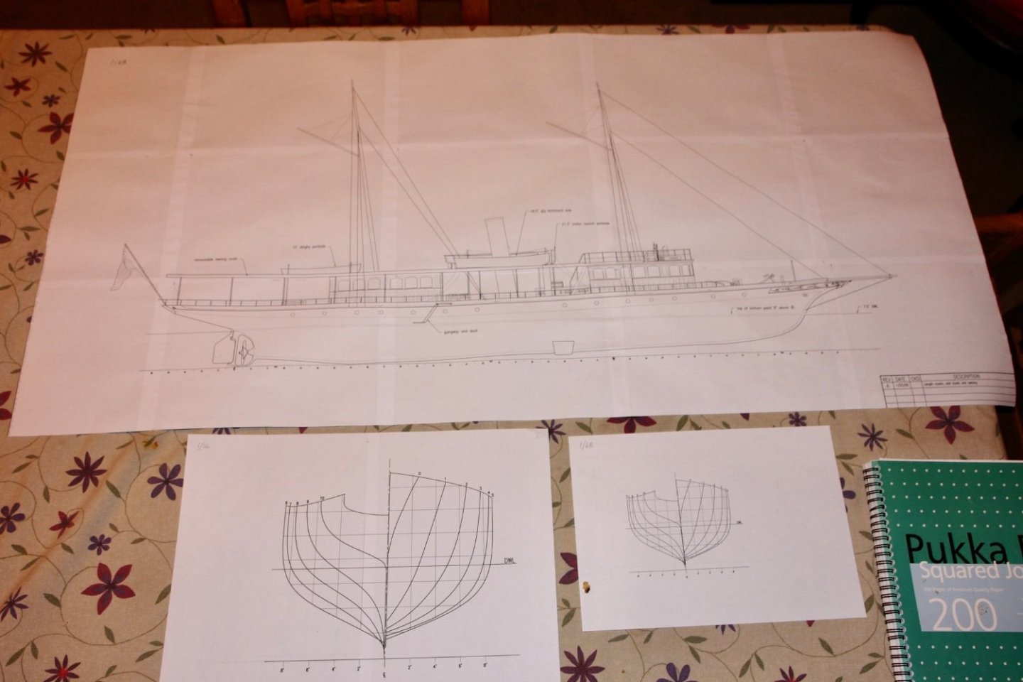
For those not wishing to download the PDF's here are examples.of some of the lines drawings.

-
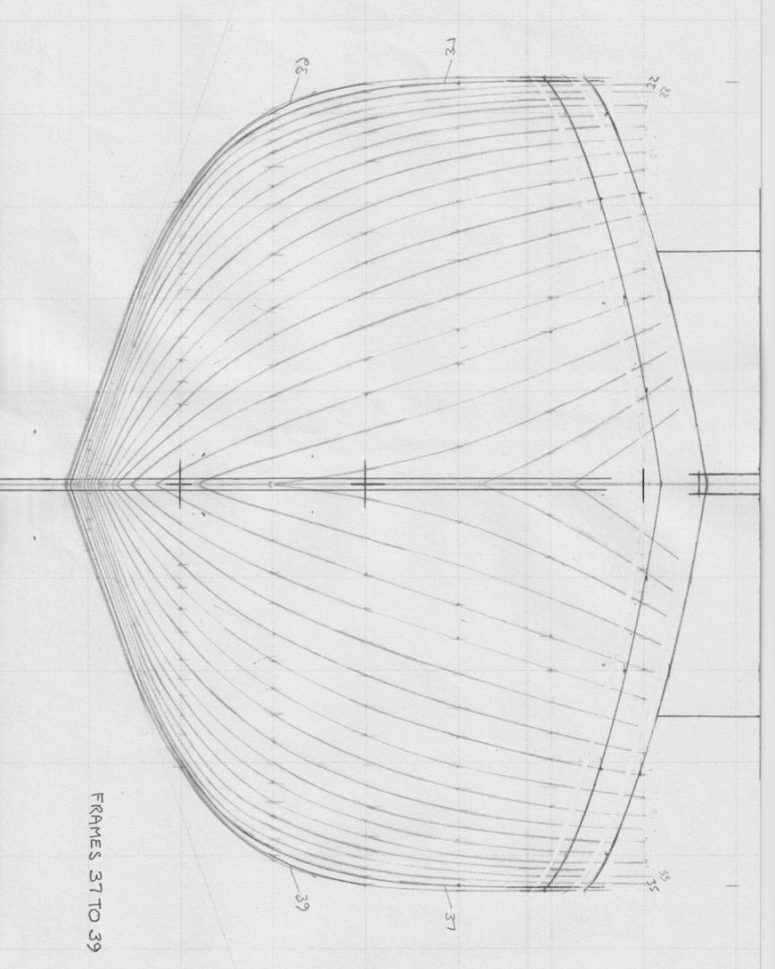
On 13 May I commented "i can start generating the hull transverse sections corresponding to the frames on Cangarda". Somehow we are now at the the last day of August and I have just completed the task. My productivity is sadly lacking, Cangarda has frames on a 18" pitch or 3/4" at model scale. The pitch is a bit over the top for model purposes so I plan to make every 2nd frame giving a frame spacing of 1.5". I have kept the numbering as per the plans supplied by Tr1-Costal Marine so every second section is missing. I took a lot of care with plotting (using the pencil, dividers and french curve method). I then spent some time reviewing the nested section to identify and obvious glitches. Generally the nested lines seem to have turned out reasonably well. I have included all the drawings as PDF files in the event that others want to have a go at building Cangarda. Full frames 01 to 35.pdf Full frames 01 to 37 to 39.pdf Full frames 41 to 45.pdf Full frames 47 to 61.pdf Full frames 63 to 81.pdf
-
Roger Amazing, but it strikes mw that with the modern trends towards "self identification" that it will take many years before parents will know for certain! Or perhaps they just delay the parties for later in life? Thanks to everyone for the good wishes.
-
Hello friends. Just touching base to confirm that I am still in the world of the living. Sorry about the absence. Lots of family duties got in the way of ship building and the workshop has been collecting cobwebs for most of the summer. The geriatric members of the family (my age) seem to have accumulated various degrees of serious illness necessitating ongoing visits. Meanwhile my son and daughters house moves respectively have provided a string of opportunities from simple decorating up to patio construction and garden re-modelling. Grandparental duties are also likely to be in sharp focus for a number of months - grandchild number 2 (boy) arrives next Friday. In my day the sex and the arrival time were a mystery but it seems that in our modern word all uncertainties have been removed 🤞. I hope to get back onto a bit of modelling in the autumn as the weather deteriorates. In the mean time I will try to catch up with all your build logs. Best wishes.
-
Thank You Valeriy
-
Valeriy, Te hull seems to have lines running along its length. I think this is to represent the steel plates that the hull was constructed from (presumably the plates were riveted together). My question was how did you simulate the these on the hull. Thank you for the details of the power plant - it looks like triple expansion steam engine. The stokers must have had a difficult life - very cramped space, lots of coal dust, lots of heat. It must have been hell.
-
Rob - the waves look very sharp (small wave length and high amplitude). I wouldn't fancy the trip.
-
Ah! Maybe in need an upgrade. There is not a lot wrong with me that a whole body transplant wouldn't fix - or maybe all I need is a better computer.
-
Valeriy I tried looking the cyclone class up but couldn't find much detail. Were they early samples of turbine powered craft or did they have reciprocating machinery? Do you know what the horse power was? Were they coal or oil fired?
-
Excellent work as usual Valerie. The stern is quite an unusual shape - neither round or flat. The props seem large in comparison to the hull but I guess she had a lot of power for her size. Is the plating simulated using card or something more elaborate? I hope you are keeping safe.
-
Barncave Shipyard by mbp521 - Scale 1:1
KeithAug replied to mbp521's topic in Non-ship/categorised builds
Very elaborate shed Brian. I think however you have missed the most important feature from your plans - the lost bits black hole! Also you seem to omitted the "where did I put that "xxxxxx" craft knife" desk. I hope you haven't got so far that you can't change the design! -
Planking the stern would have been difficult. I think your alternative plan is the right way to go
-
Keith - your interpretation of photos is impressive. I think my eyes need an overhaul.
-
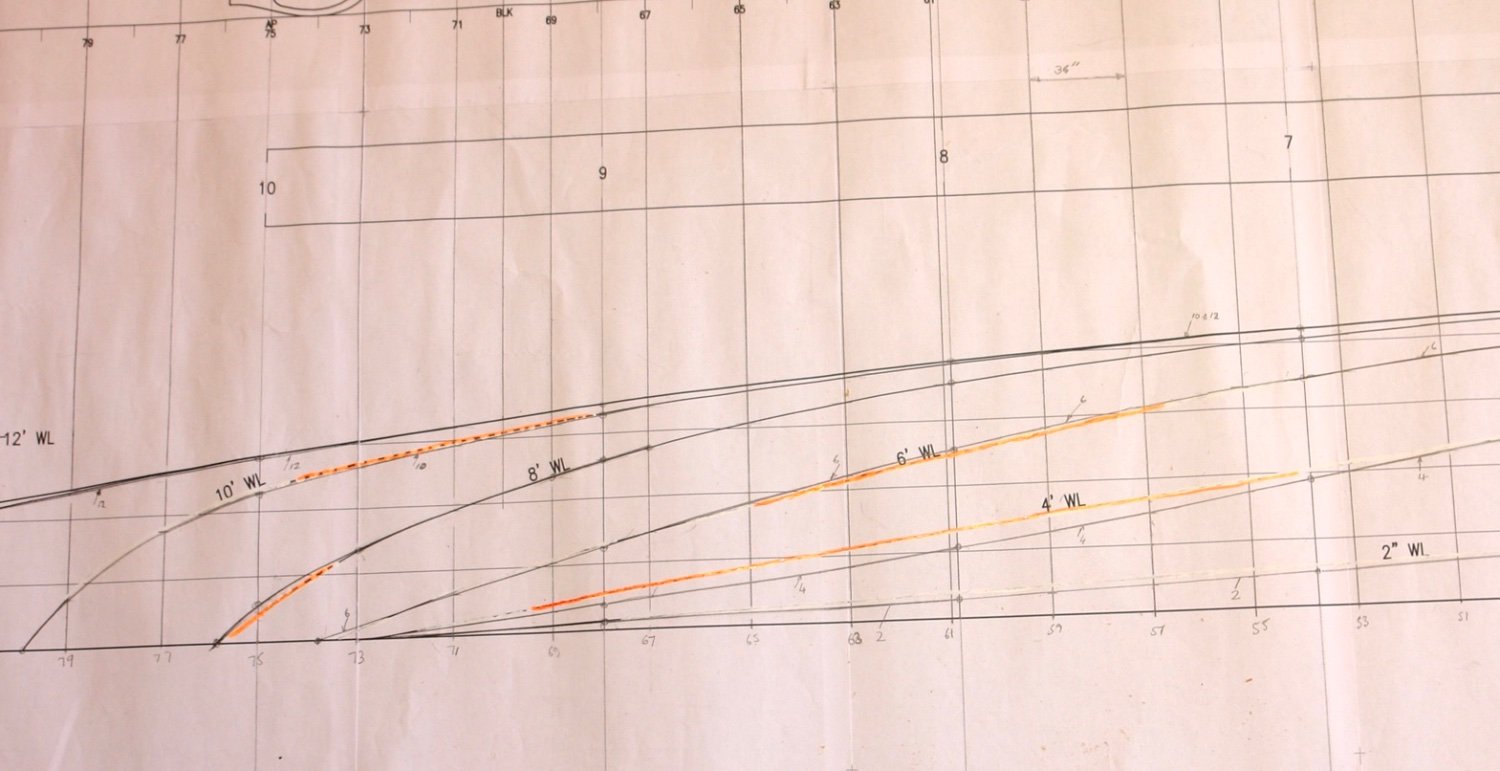
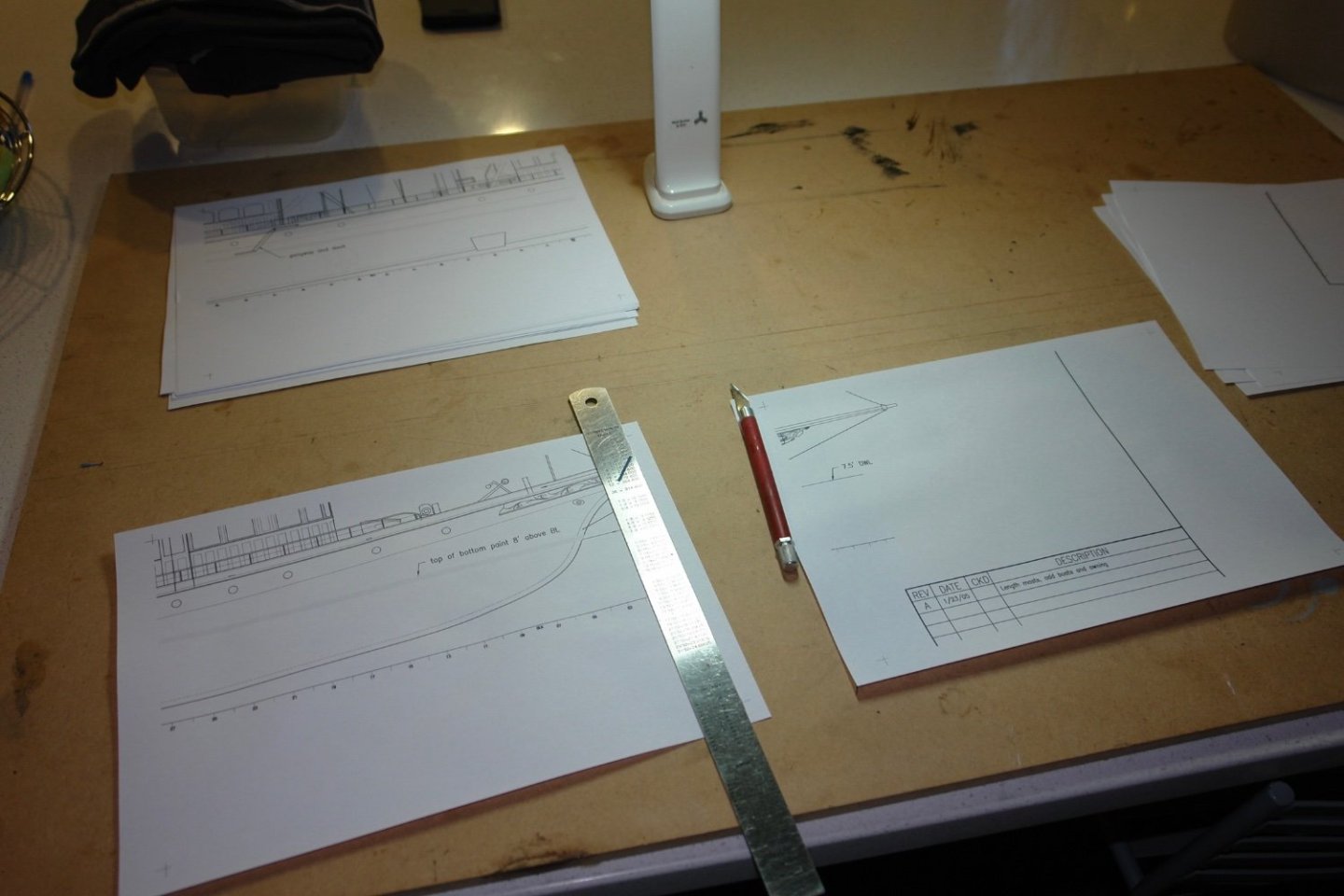
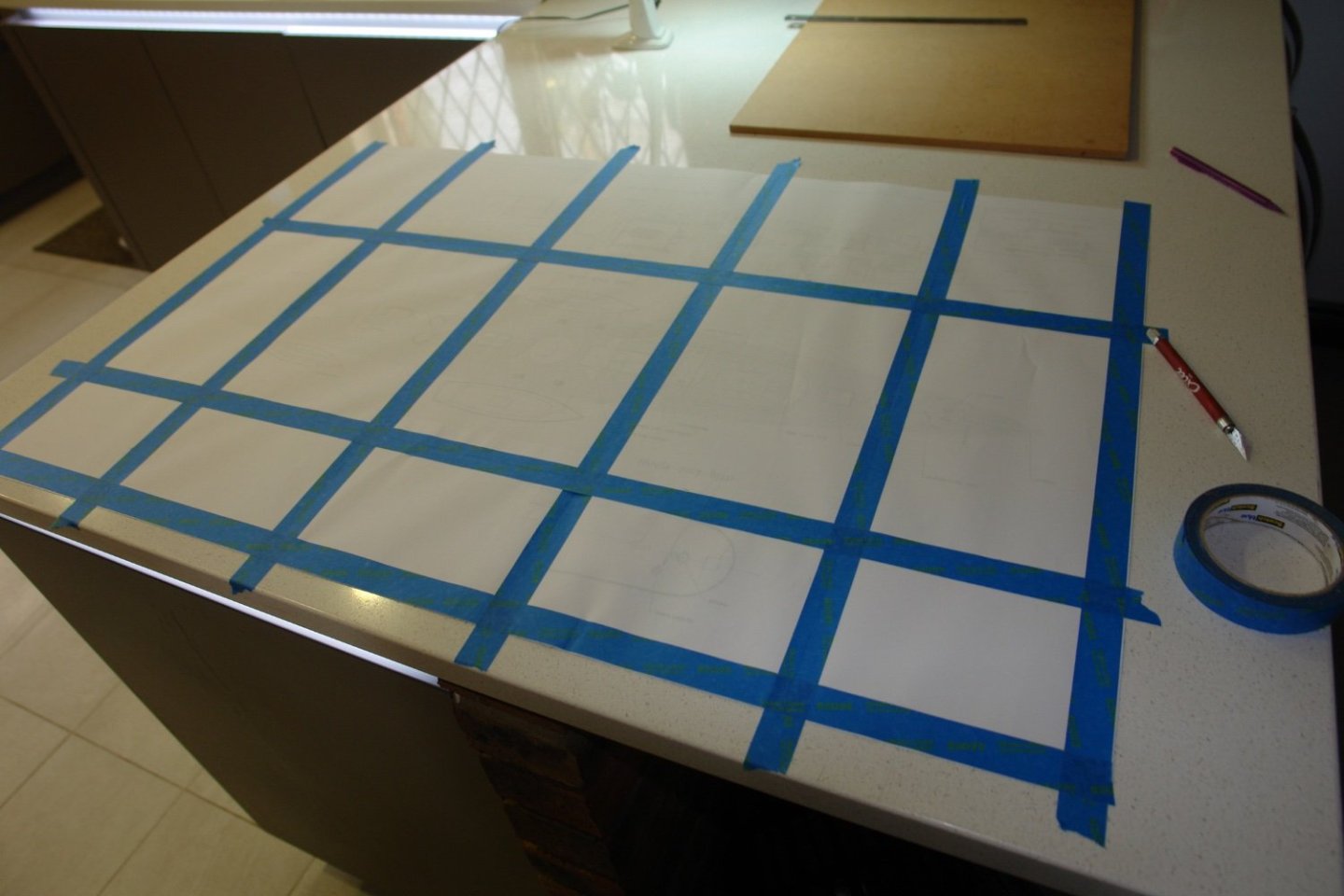
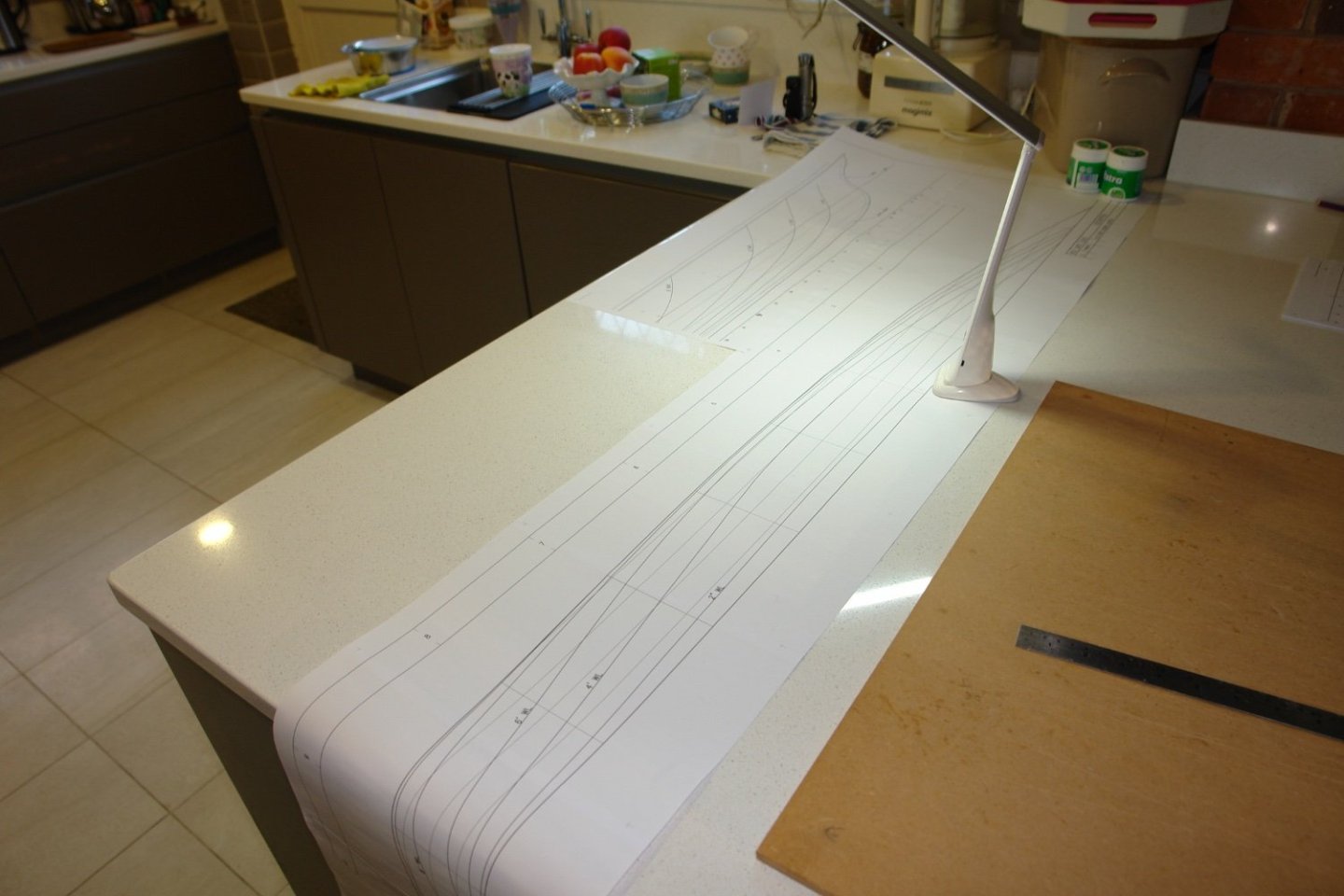
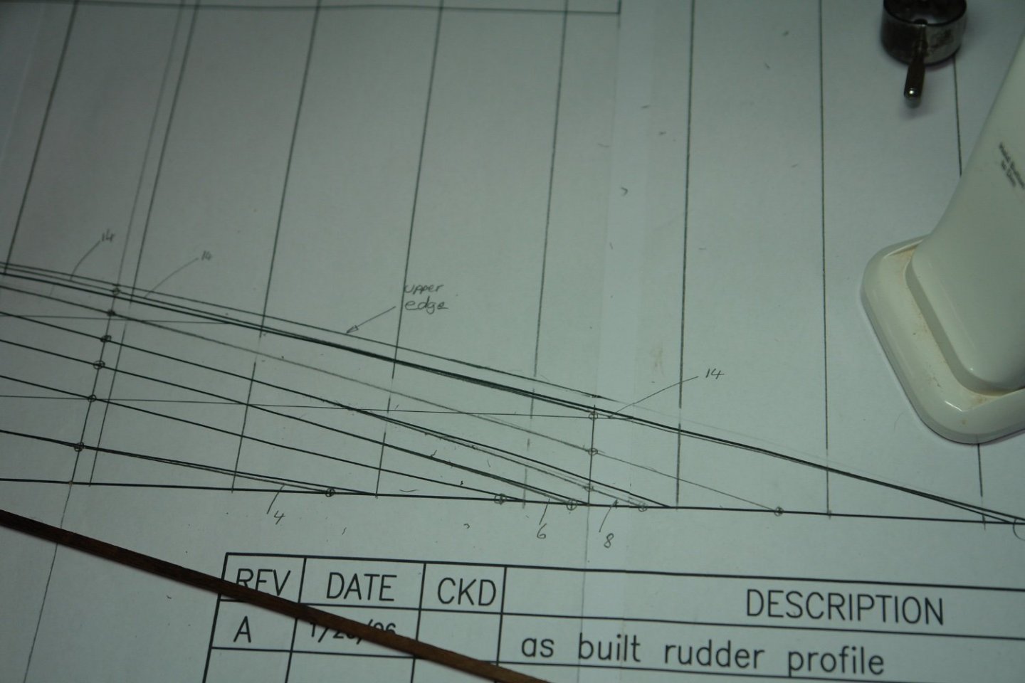
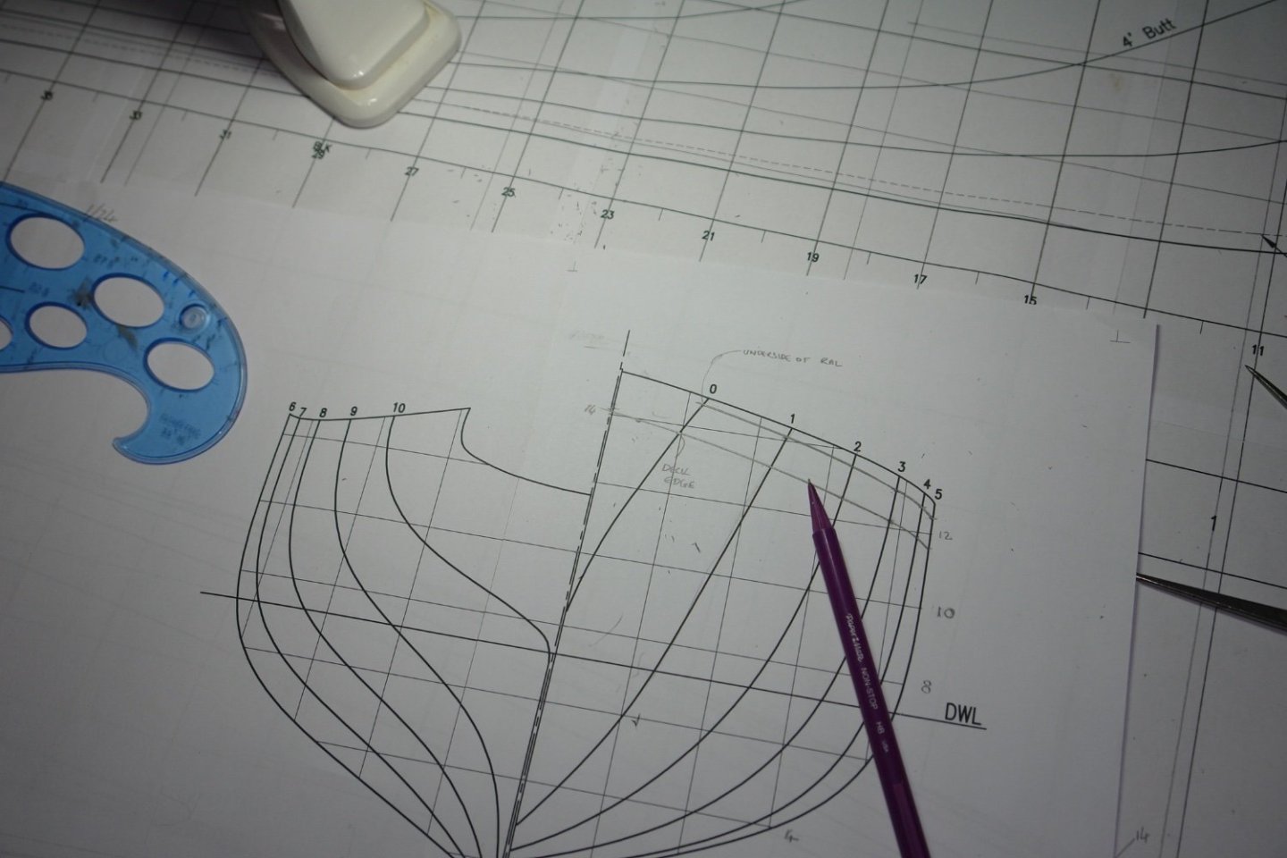
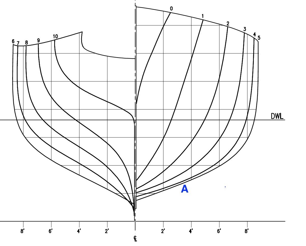
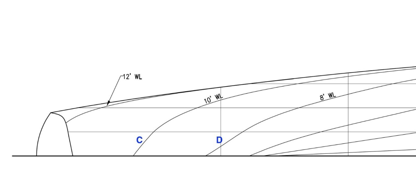
After a bit of a layoff I am back at it. Somehow I picked up an unusual lung bacterial infection that required 3 rounds of different antibiotics to knock it on the head. The last lot seemed to do the trick and i'm now on the mend. I have been doing a lot of work on the hull lines drawing. You will probably recall Mr Rutherfords comment to the effect that the original lines were not available and the lines drawing was produced from a scan of the hull. I don't know in detail how scans are done or indeed the details of the curve fitting programme used to generate the lines. Clearly though the small number of scan points has presented a challenge the curve fitting programme. Having printed out the the previously mentioned drawings at 1:24 scale on A4 sheets i joined them together paying particular attention to alignment and overall dimensions. The breakfast bar came in quite handy (despite some protests). I played the illness card which seemed to have the desired effect. Looking at the lines drawings prompted a few questions. On the transverse sections at section 4 near position "A" there is a slight curvature. On the various photos I have the hull seems quite flat at this position, much more like frame 5. On the horizontal sections near the stern the lines at points "C" and "D" seem to have odd local curvatures and I guessed that this was down to the curve fitting programme struggling with lack of data. Rather than accept the lines I decided to check the transverse, horizontal and longitudinal sections against one another starting by plotting the transverse section on top of the horizontal sections. This revealed a number of discrepancies. Near the stern the 4'WL plot deviated quite a lot from that line on the horizontal plan. The orange line below shows the original plot line while the new line below it is the line generated from plotting out the transverse sections. Smaller deviations were also revealed on the 6",8"and 10"WL plots, here again the orange lines are the original and the black lines are the projections from the transverse plots. There were similar (but smaller) discrepancies towards the bow. I then plotted the longitudinal section back on to the transverse sections which revealed discrepancies at the rail. The pencil lines show the runs of the rail and deck edge. While none of the discrepancies were major I decided the best way forward was to get the plan, side and frontal lie drawings in agreement before generating the hull sections for build purposes. This is now complete and i can start generating the hull transverse sections corresponding to the frames on Cangarda.

-
Great detail on the boiler but will it be visible?