KeithAug
-
Posts
3,980 -
Joined
-
Last visited
Content Type
Profiles
Forums
Gallery
Events
Everything posted by KeithAug
-
 Keith. Unfortunately of late my good looks have deserted me. In fact now that I think of it they departed me some years ago. I think I’ll lock myself away and concentrate on modelling ( of the boat kind ).
 -
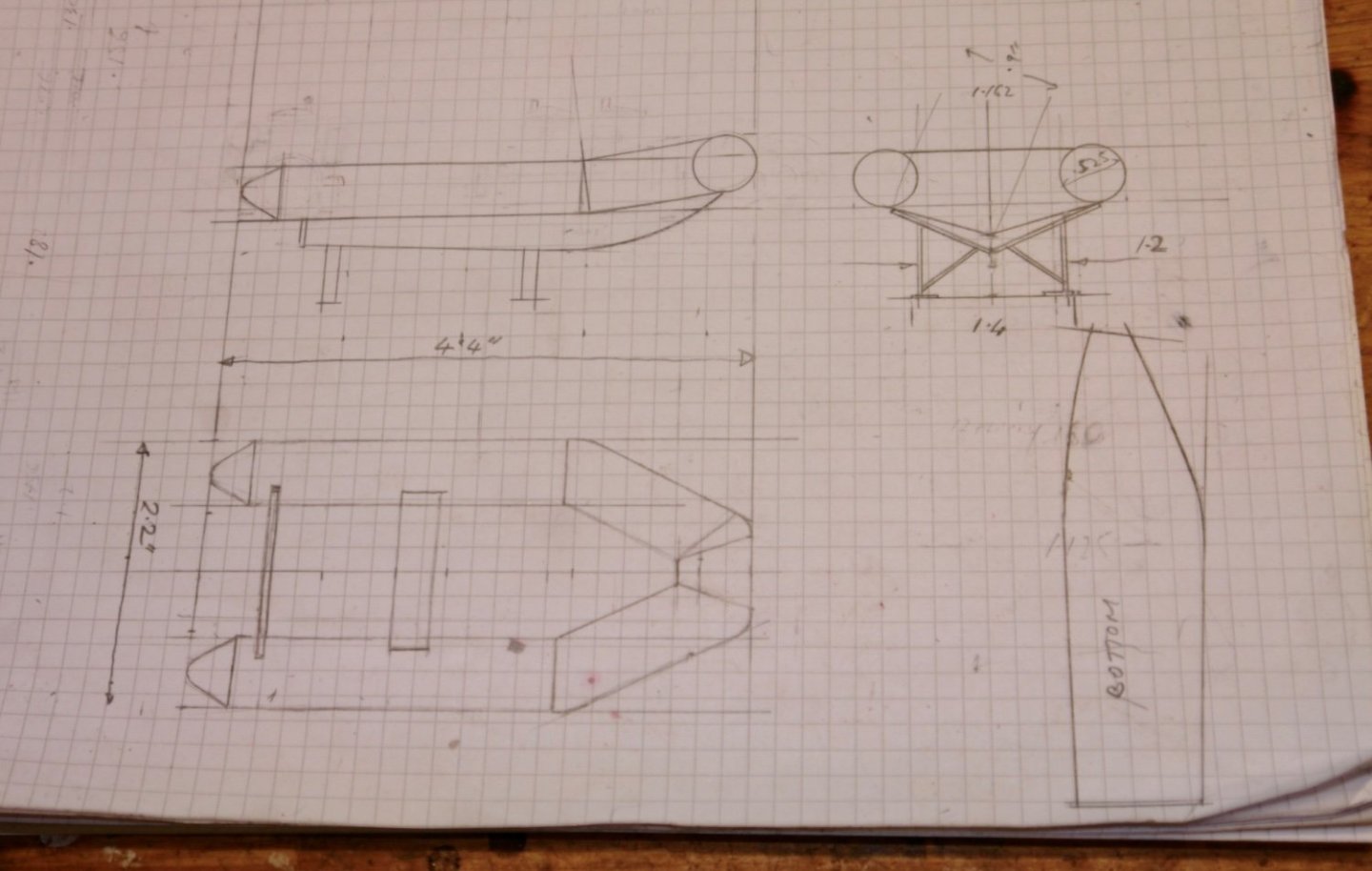
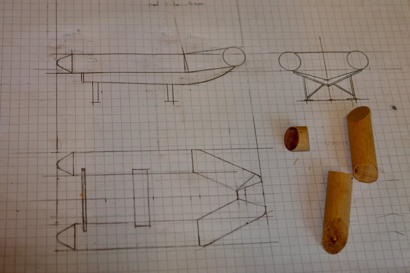
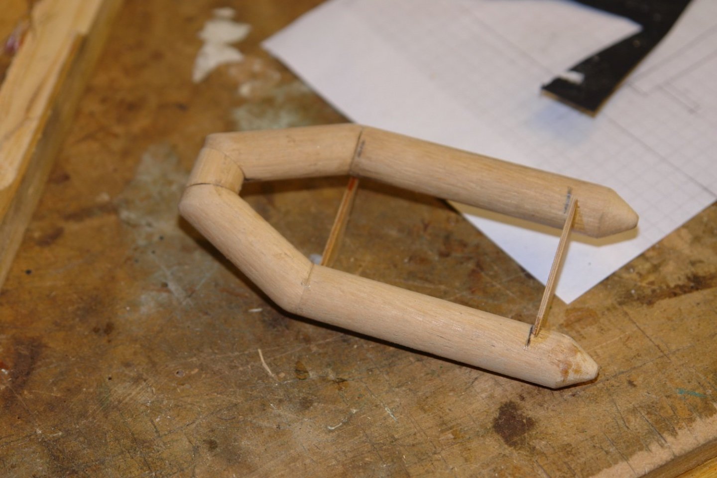
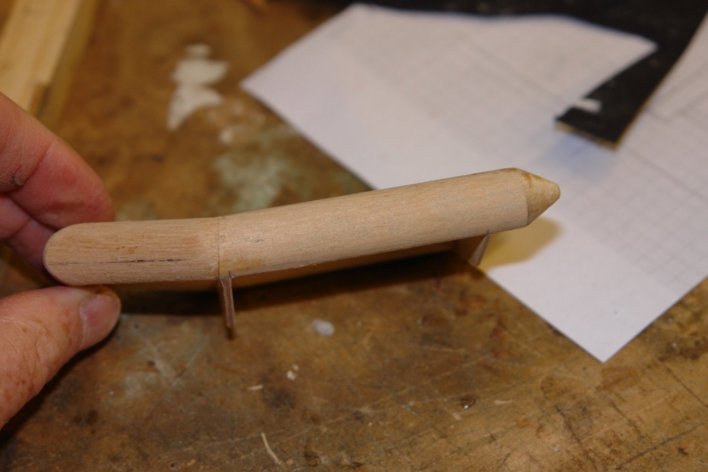
Thank you Eberhard, Druxey, Keith, Pat, John, Rick, Richard, Allan and Gary for you comments. Before I put the final touches to the launch I though I would have a go at the RIB. I dithered over making this because It feels out of character with the original Germania. However it is a feature of Germania Nova and in the end I decided it had to be installed. I had the sizes of the RIB from the small scale plans and so sizing wasn't a problem. I started with a basic sketch of the rib and support cradle. The ribs overall dimensions are 2.2" x 4.25" The inflatable sections are about .450" diameter and were turned from a medium hard dowel. The only tricky aspect to this stage of construction is sorting out and cutting the compound angles at the intersections. This was done on the table saw. Once cut the sections were glued together, the gluing process being assisted by the transom frame. The forward section cants upwards. A flat profile would have been easy, but it wasn't right. I haven't got any further so more next time. But as an aside I was finding the storing of all my previously made bits a pieces a challenge. However with age my wife consumption of face enhancements is keeping the cosmetics industry booming and her discarded glass pots do come in handy. This is proving to be a very expensive storage system - but the supply chain is very secure.

-
HMCSS Victoria 1855 by BANYAN - 1:72
KeithAug replied to BANYAN's topic in - Build logs for subjects built 1851 - 1900
Pat - ref PCB drills. I only use them on a drill stand. Freehand drilling is very difficult without imposing side loads and it is the side loads that inevitably lead to breakage. I drill most of my thin brass sheet with PCB drills and don't find the cutting angle causes grabbing. I do however feed the drill slowly. Here drilling by machine helps because the rack on the drill feed controls the drill at the point of break trough. Where ever possible I drill the brass with some form of backing board (usually a piece of hard wood). This also helps prevent grabbing. Of course these techniques / precautions to some extent depend on the geometry of the component and may therefore not always be applicable. The brass I use tends to be hard brass. I hate the machine characteristics of soft brass which has a much greater tendency to grab. You comment about the description of the solder as "silver solder" is quite interesting. Over here silver solder is specific to very hard solder - usually just as hard as the metal being soldered. As Eberhard explained this typically melts at circa 600 deg c and the joint formed is just as strong as the parent metal. Low temperature non-lead based solders melt at much lower temperatures and are generally soft in comparison to the material being soldered. Because they are soft they are easily cut with a craft knife ( I am wondering if this is true of the solder you are using?). When soft solders are used to butt a thin sheet end to a plate they form a very weak joint and in my experience this inevitably fails under anything more than light pressure. By the way thank you for introducing me to resistance soldering. I hadn't come across it before but it looks quite interesting.- 1,013 replies
-
- 3
-

-
- gun dispatch vessel
- victoria
- (and 2 more)
-
Nice planking job and I loved the build sequence photos.
-
HMCSS Victoria 1855 by BANYAN - 1:72
KeithAug replied to BANYAN's topic in - Build logs for subjects built 1851 - 1900
Pat, makes it a lot more understandable now. Also PCB bits are very sharp and while being fragile are relatively cheap. Might be worth a try.- 1,013 replies
-
- 2
-
-
- gun dispatch vessel
- victoria
- (and 2 more)
-
HMCSS Victoria 1855 by BANYAN - 1:72
KeithAug replied to BANYAN's topic in - Build logs for subjects built 1851 - 1900
Eberhard, I also had that thought but I also thought that at that temperature the brass would be starting to glow. My experience is that it is very difficult to silver solder very thin brass as the flame is apt to melt the brass. Perhaps Pat could help us with more detail on his soldering process and soldering material.- 1,013 replies
-
- 1
-
-
- gun dispatch vessel
- victoria
- (and 2 more)
-
HMCSS Victoria 1855 by BANYAN - 1:72
KeithAug replied to BANYAN's topic in - Build logs for subjects built 1851 - 1900
Pat - I am probably being daft but couldn't you drill the holes before soldering?- 1,013 replies
-
- 3
-
-
- gun dispatch vessel
- victoria
- (and 2 more)
-
Phil Every time I look at this build I am struck by the quality and detail of the plans. Given the era of the vessel I think the plans are remarkable.
-
The clinker planking is nicely done. I always think it is quite difficult to pull this off successfully. Good work.
- 30 replies
-
- 4
-
-

-
- small
- clinker built
- (and 2 more)
-
HMCSS Victoria 1855 by BANYAN - 1:72
KeithAug replied to BANYAN's topic in - Build logs for subjects built 1851 - 1900
Pat An interesting bit of brass work. It just goes to show there are may ways to skin a cat. The PE looks quite crisp to me, did you do the etching or did you contract it out?- 1,013 replies
-
- 2
-
-
- gun dispatch vessel
- victoria
- (and 2 more)
-
Dear Keith I was just catching up but your devastating news has set me aback. I think your loss is something that few of us could contemplate and my heart goes out to you and your family. Any words that I can offer are probably of small comfort but at this time it is worth remembering that our departed loved ones do live on in our memories and hearts. Good be with you my friend. With greatest sympathy. Keith
-
You have done quite a lot in two years. Some of us are quite a lot slower!!!! She is looking wonderful and like you I thought the illuminated bow shot was real cool.
-
The plating is very impressive - did you say earlier that you had checked that water would not get behind it and delaminate it?
- 454 replies
-
- 1
-
-
- Union Steamship Company
- Stepcraft 840
- (and 3 more)
-
I have to say that I found your rust bucket to be a charming choice of vessel. I wish you luck with your first scratch build.
-
The hull frames are looking very good. You have not lost your touch. One frame a day seems like a good target allowing plenty of time to admire your own handy work, and of course spot and correct any anomalies. I'm glad you are starting to feel better, I hope things accelerate from here. It is still a bit damp over here😐.
-
Thank you Chris. It is a bit too shiny at the moment so I plan to knock it back a little with fine wire wool.
-
It seems to be going very well Michael. I am assuming from your comment that finish to the hull is going to leave the planking runs visible?
-
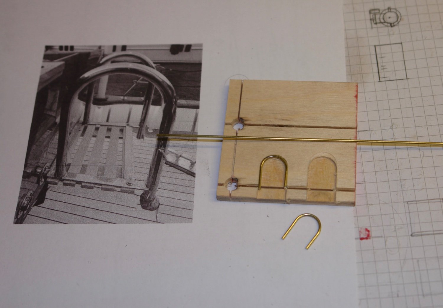
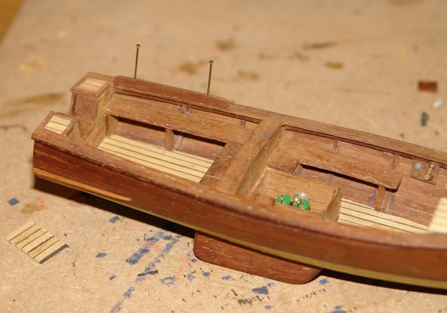
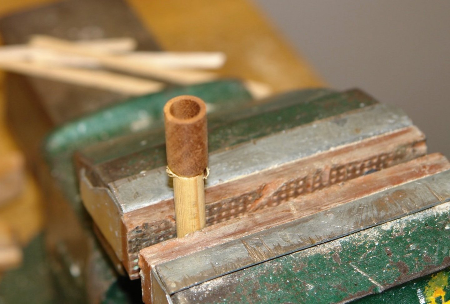
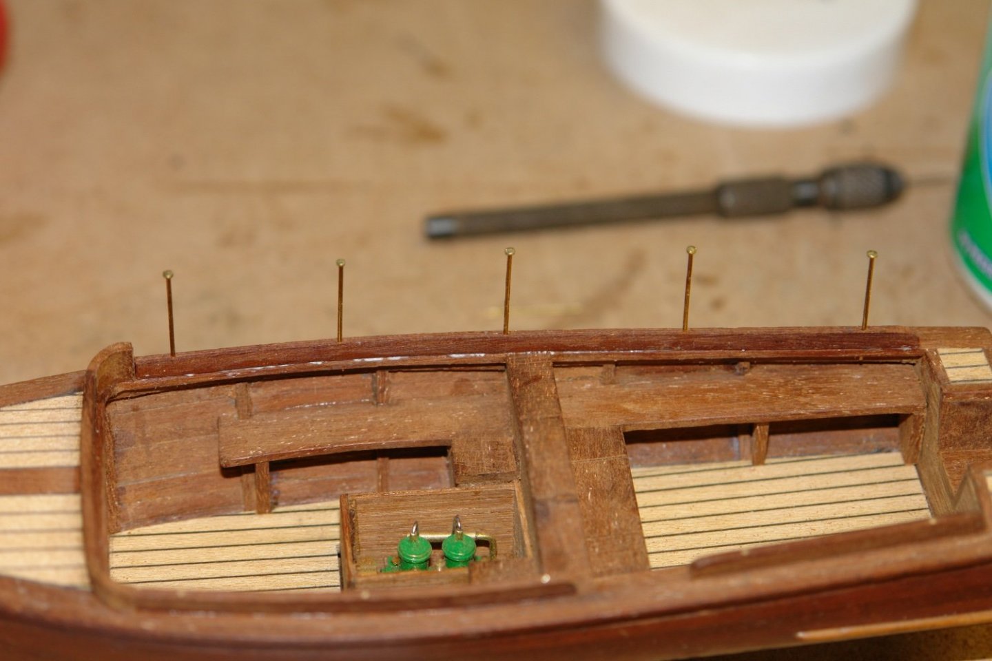
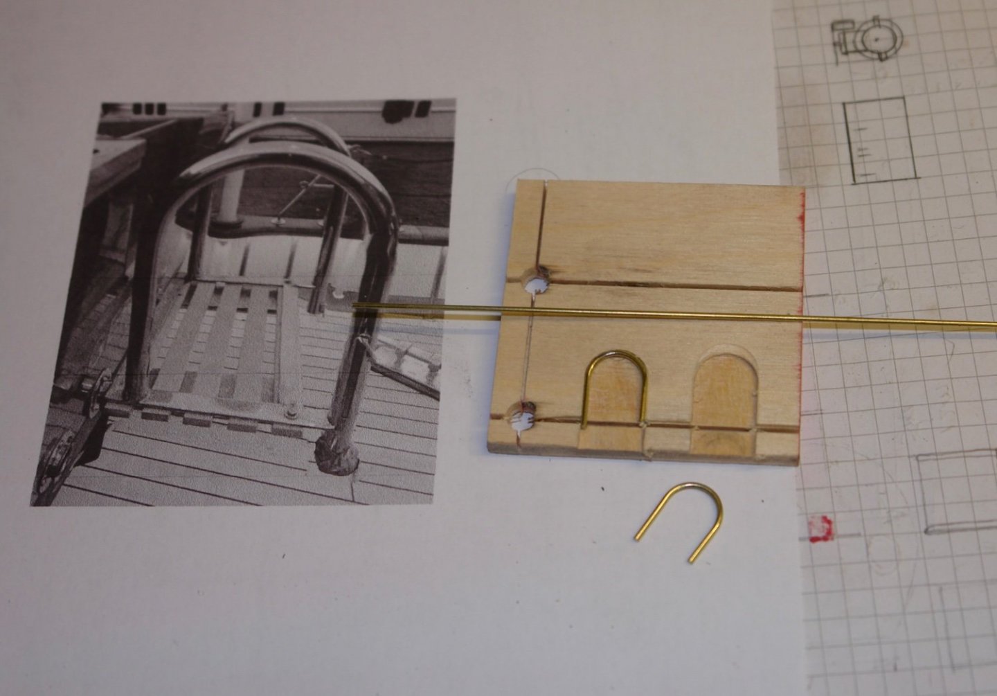
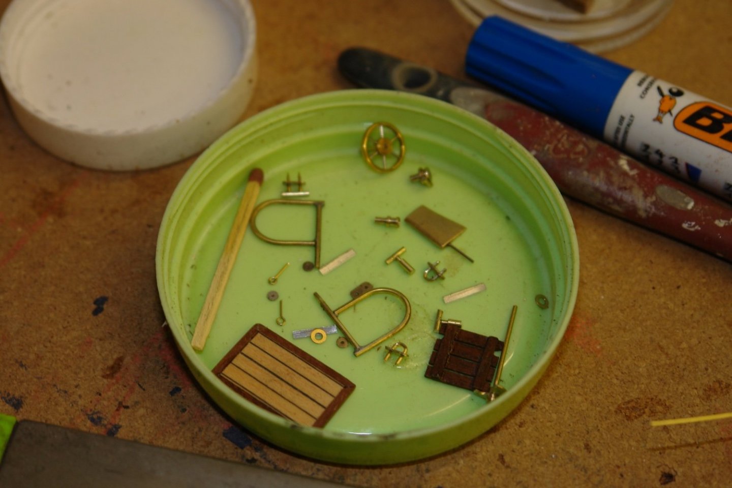
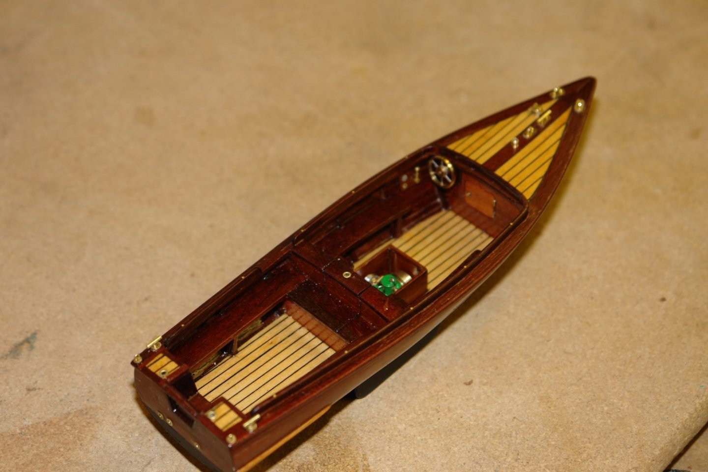
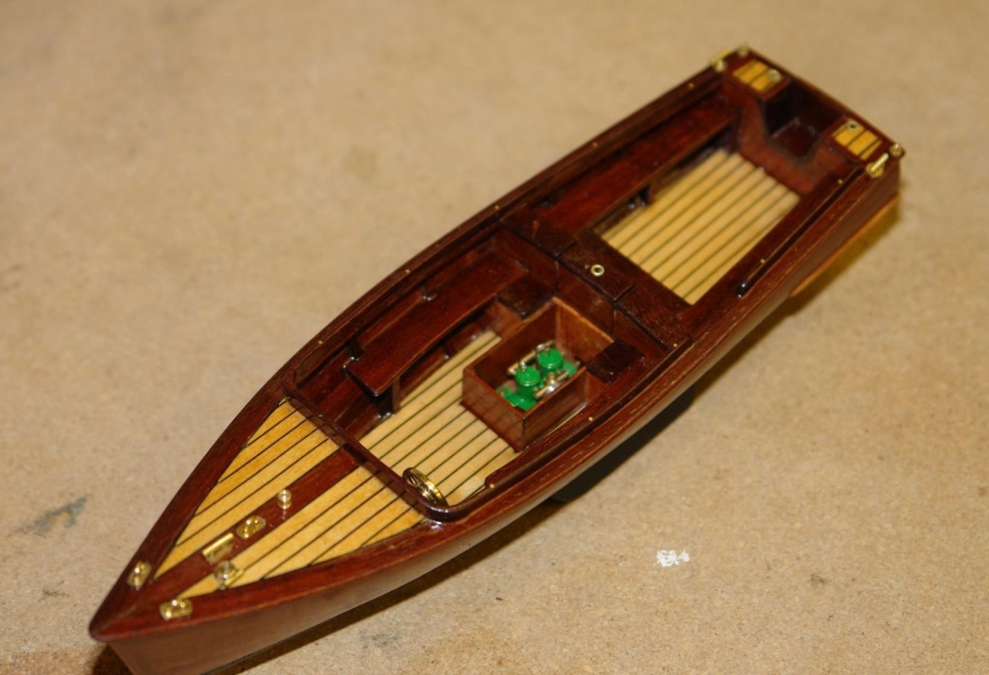
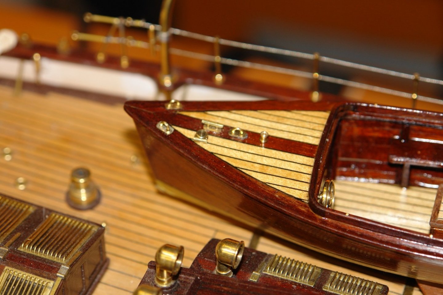
Thank you Druxey, Andy, Tom, Mark Michael and Pat. I have had a few days away and inevitably outside jobs and getting the garden in shape is taking much of my time. However I did get some time in the shipyard over the weekend. With the cap rails in place I moved on to the fore deck planking. The small aft deck pieces were also installed. I also started to make the spray rails here the first is pinned in place prior to gluing. On the rear face of the fore deck is a bit of trim with fillet radii where it joins the cap rails. I cut the fillet pieces first. And then inserted the trim and fillet radii. The spray boards also have a fillet piece where the cross board joins the side boards. I made the fillet as a tube before cutting out the necessary fillet pieces. I then installed all the spray boards. I also made an angled facia for mounting the wheel. I then sanded the upper profile of the spray board and tried the wheel again. I then made the lift out access board at the stern. I then diverted my attention to the various deck fittings etc. I started with the hand rails for the swimming step. I made a small jig to aid the process of making these. A while later I had most of the fittings done. I then spent some time on sanding and finishing before attaching the various fittings. I have yet to install the swimming step.


-
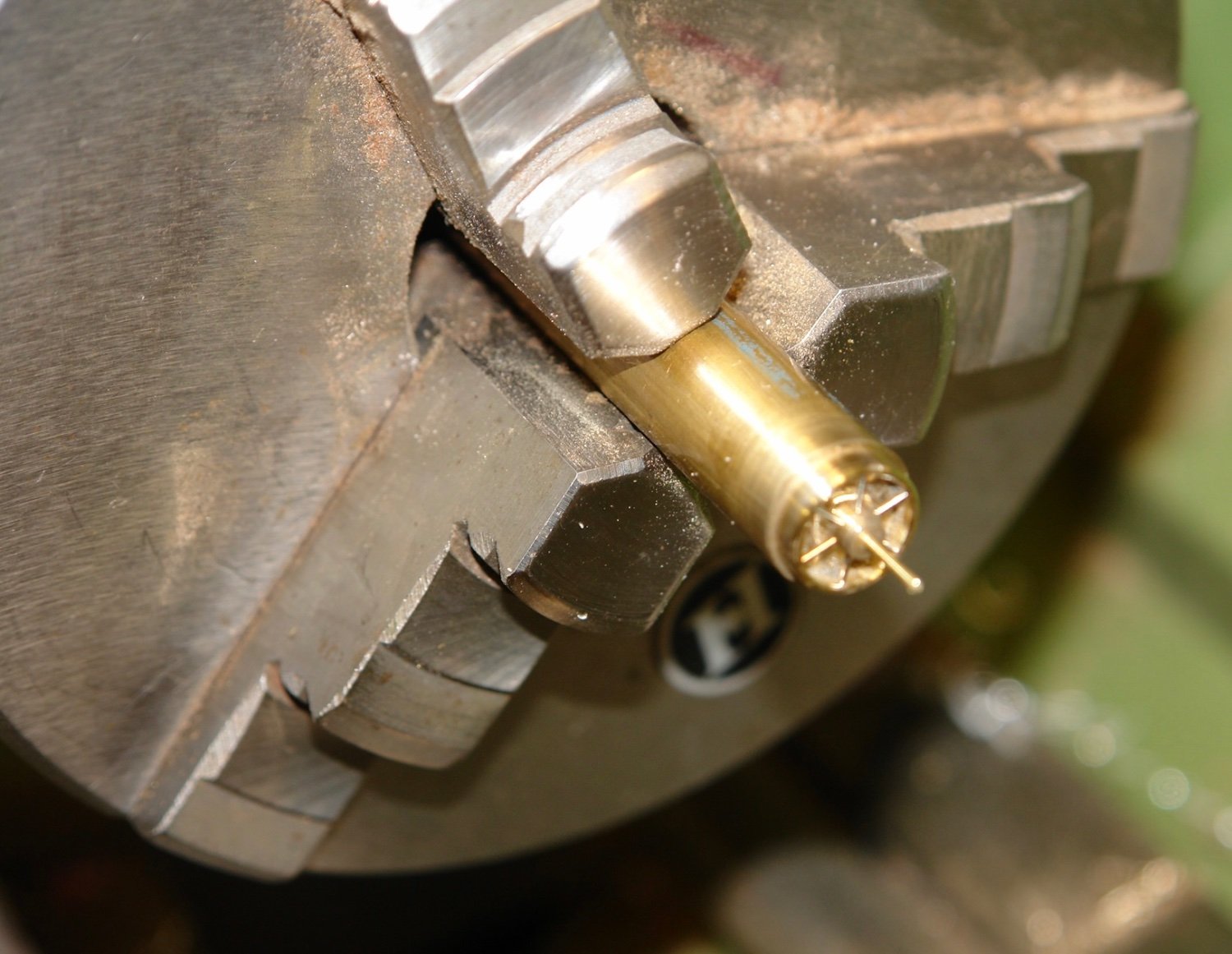
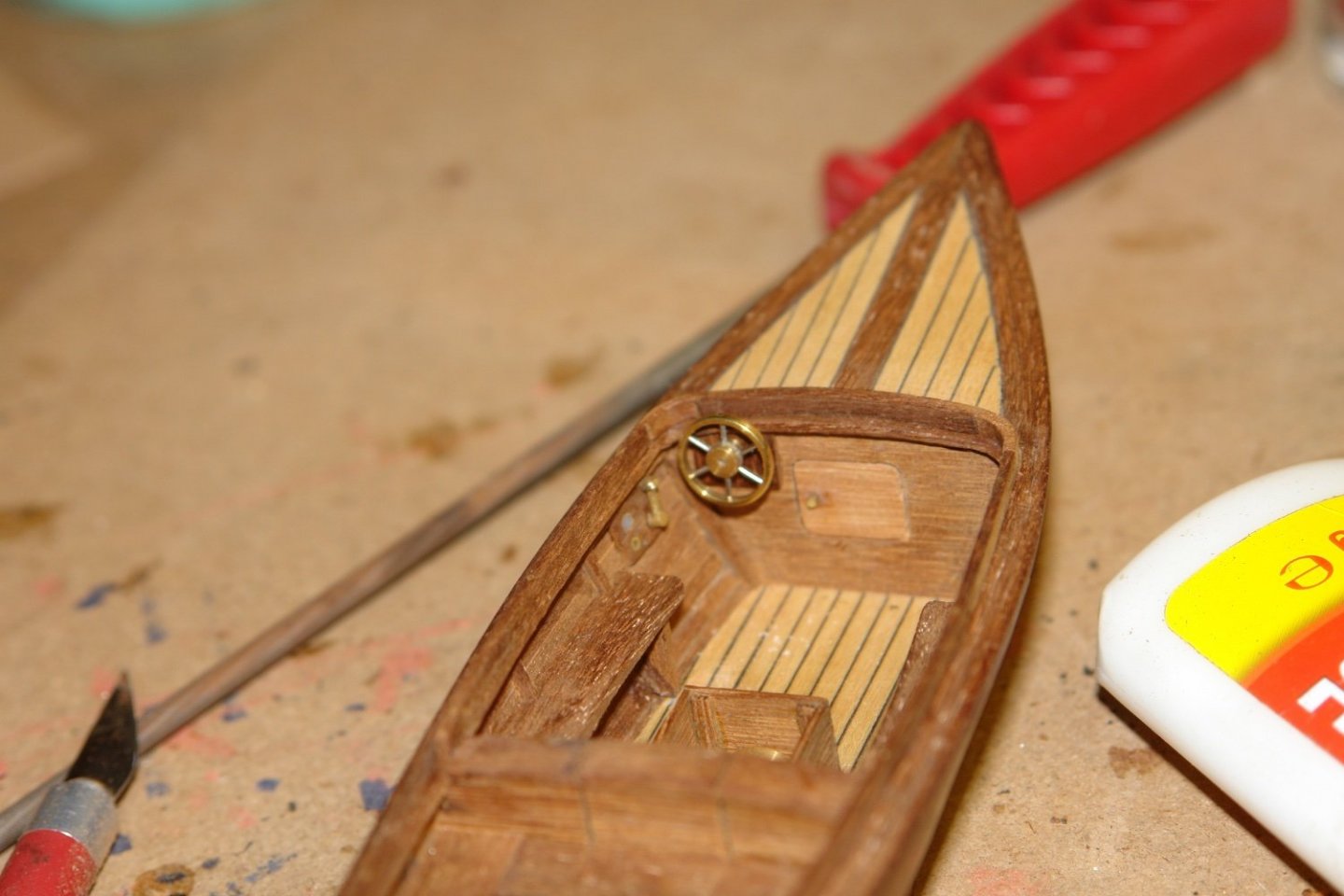
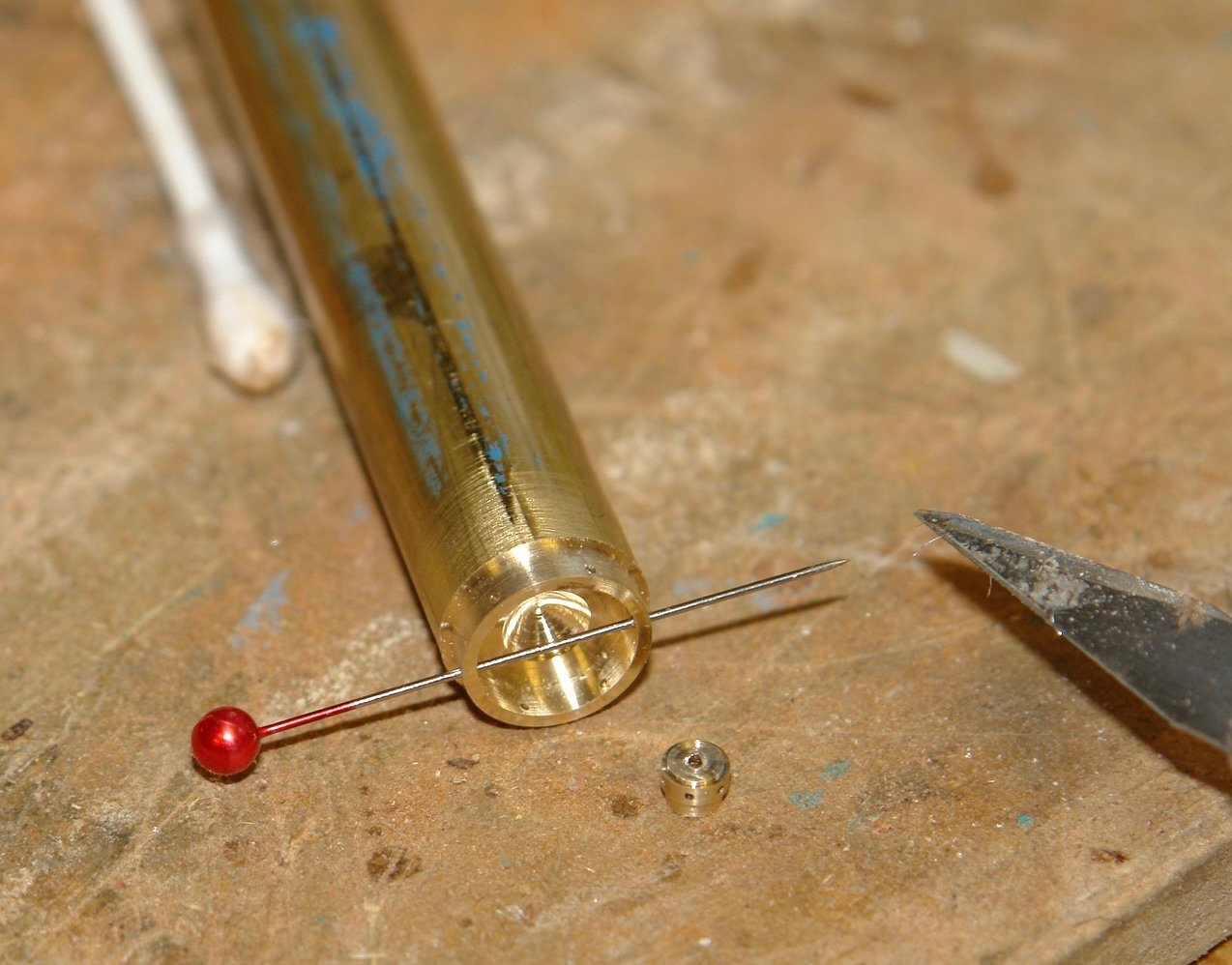
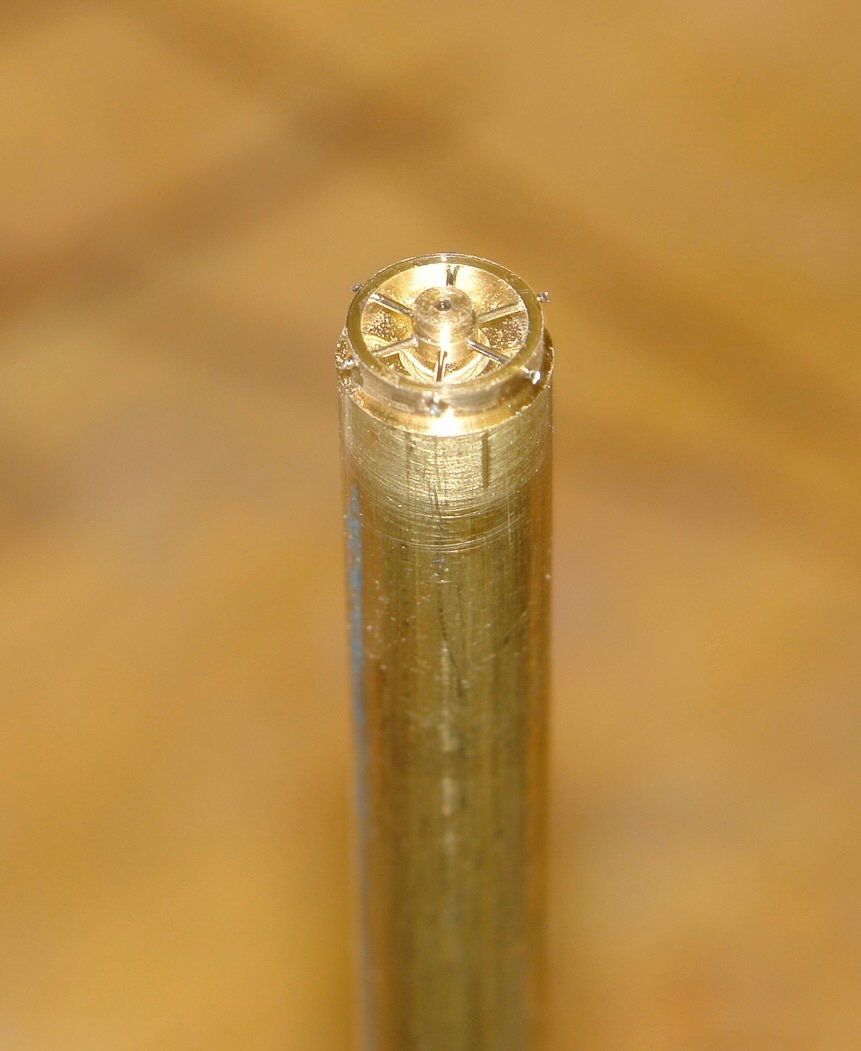
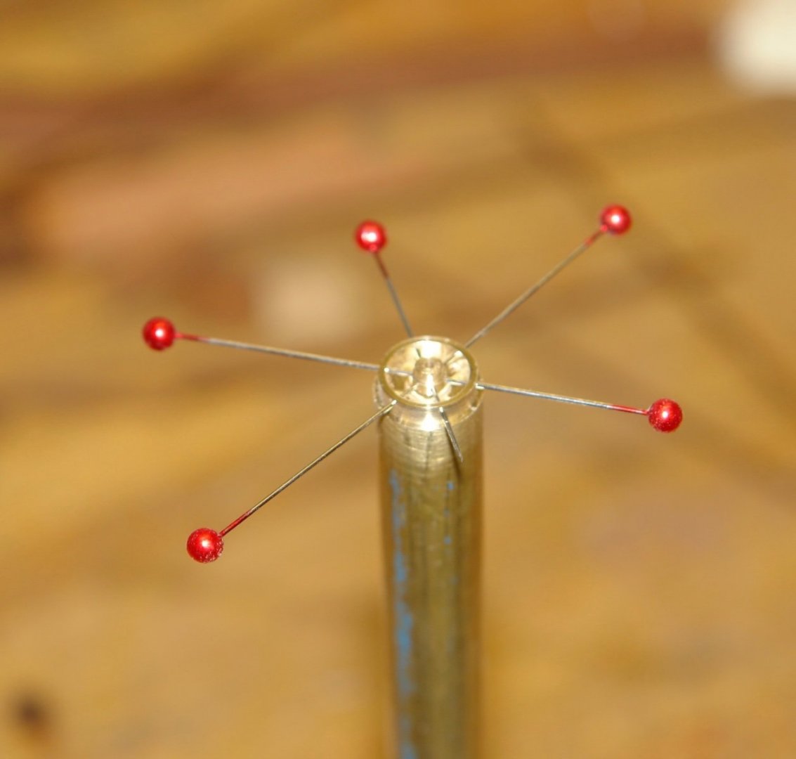
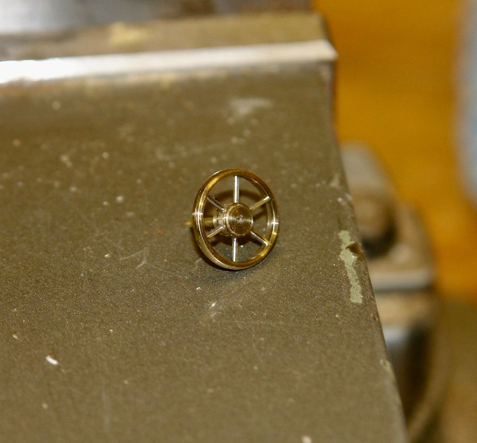
Thank you Ken and Pat for your comments. Thanks to everyone for the likes. I had a bit of fun making the boats wheel. I sized the wheel at .44" outside diameter with a .16" hub (15.8" OD at full size) I started with .5" brass rod which I reduced in diameter to .44". The bore was then drilled out to .375" leaving an annulus .032" thick. 6 equi-spaced .027" dia holes were then drilled round the annulus. The hub was drilled with 6 more holes and then parted off from a .160" dia rod. 5 stainless steel pins were then inserted to support the hub (one through pin and 4 further pins) these were glued in place with CA. The pins were then cut off prior to the .5" rod being re mounted in the lathe chuck. The pins were then machined flush and hub bore was re drilled and a shaft inserted. The edges of the annulus were then rounded before the wheel was parted off. The wheel was then flipped round and held by the shaft for the reverse of the annulus to be carefully profiled. A fun little job😀

-
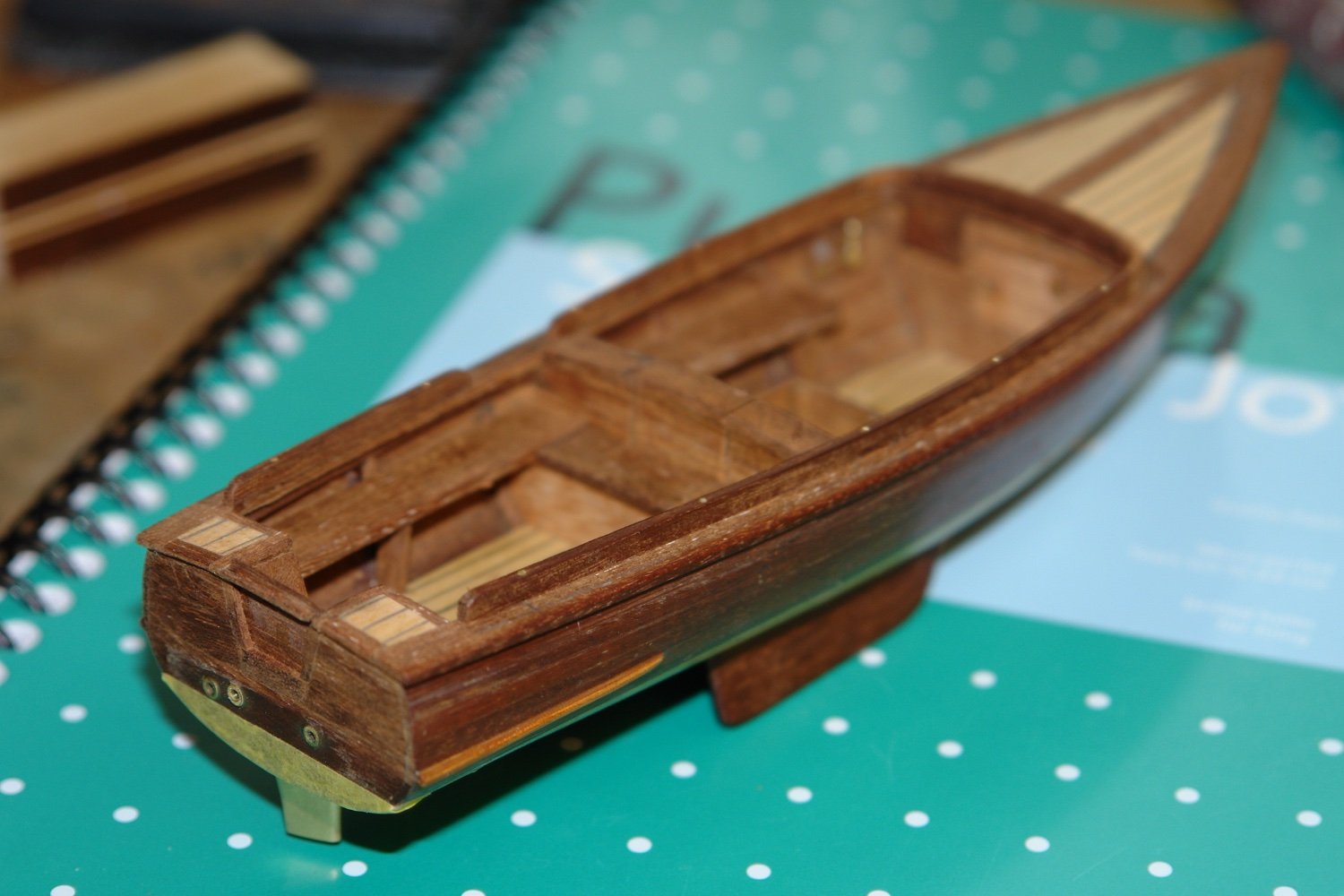
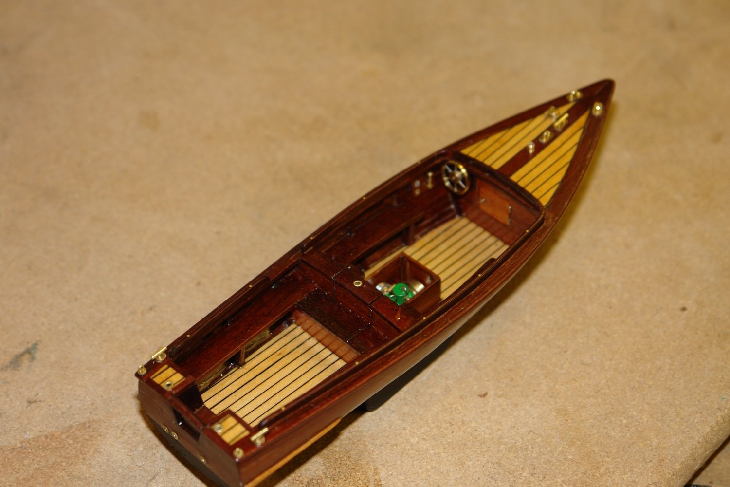
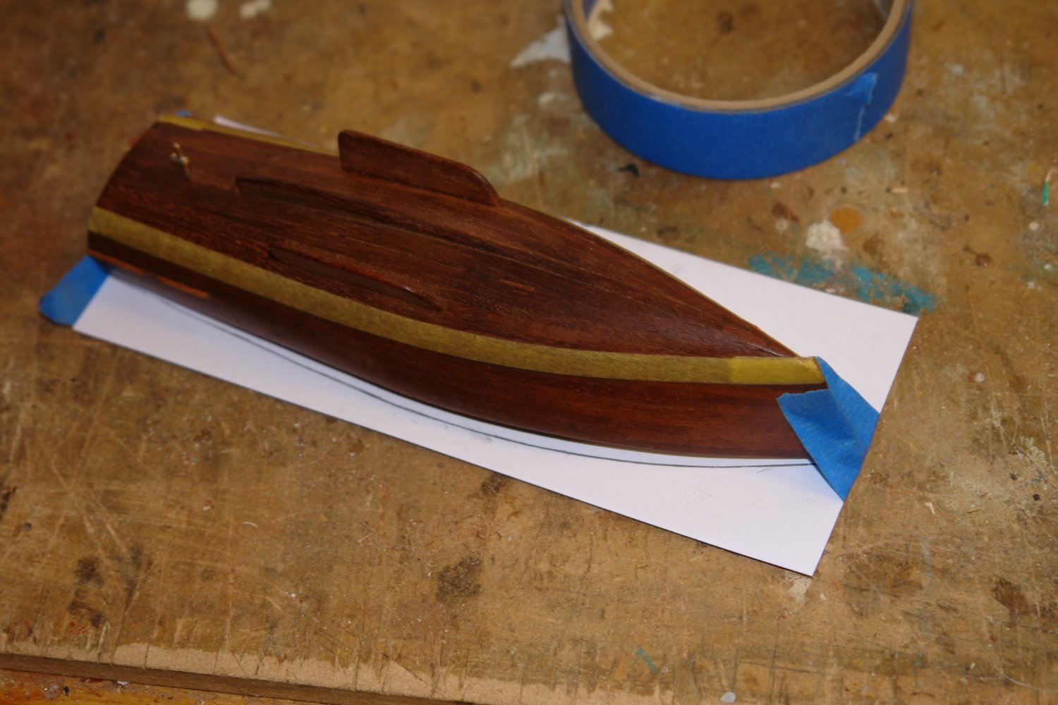
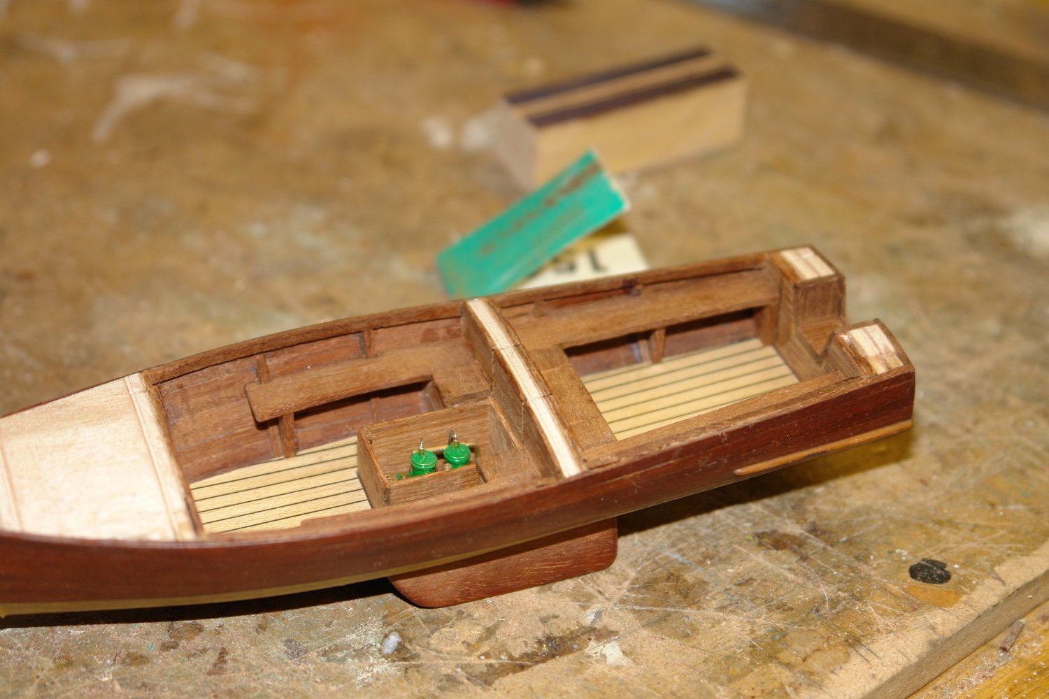
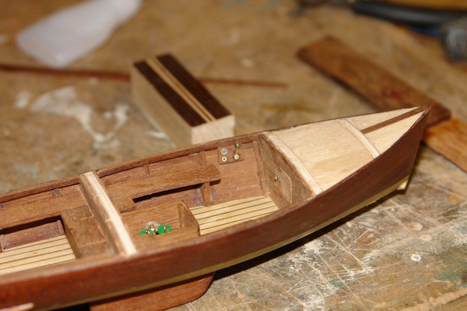
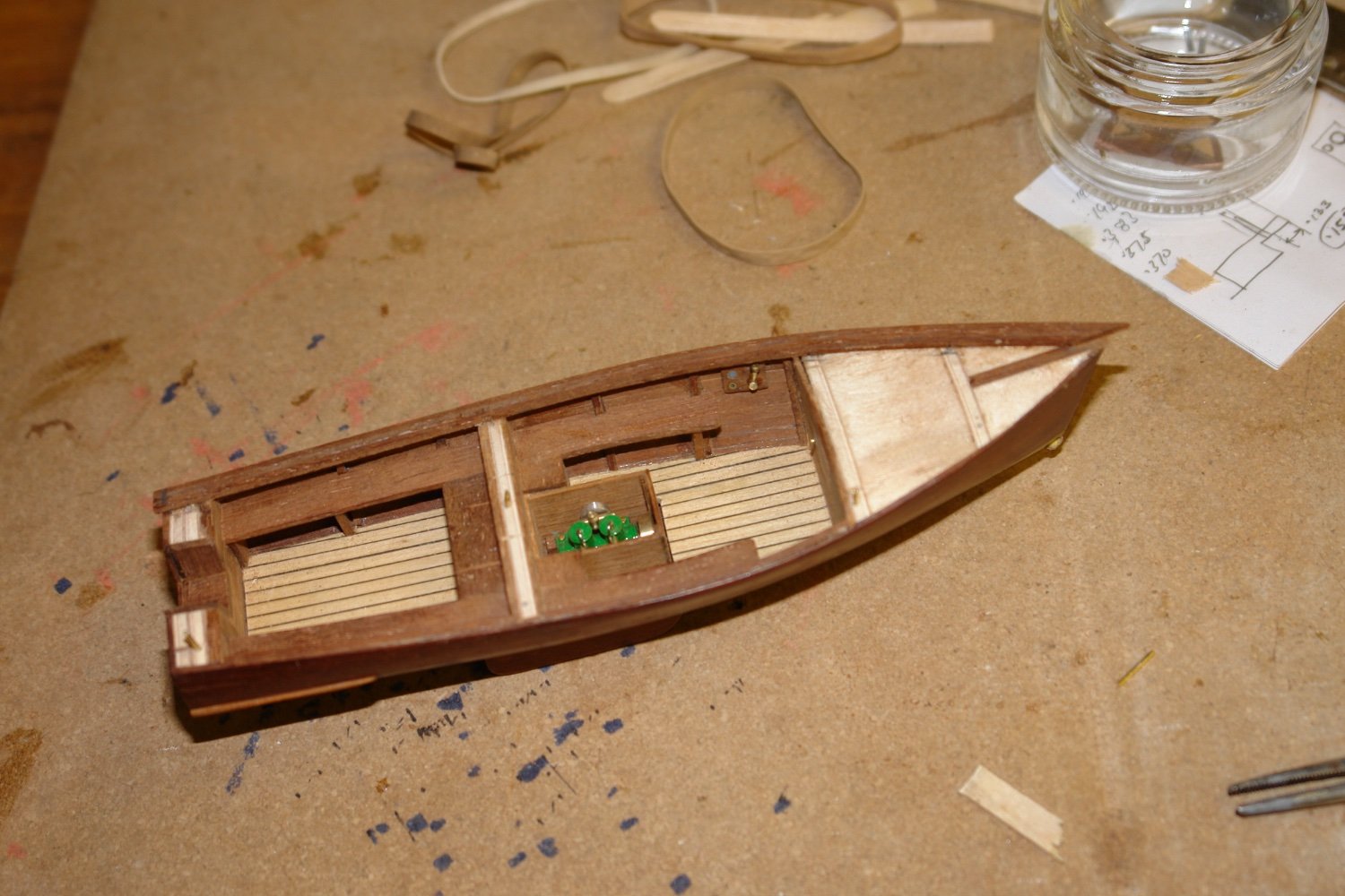
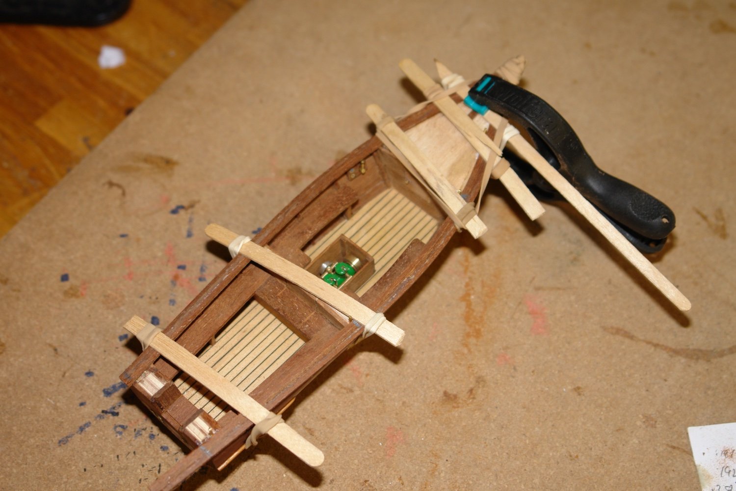
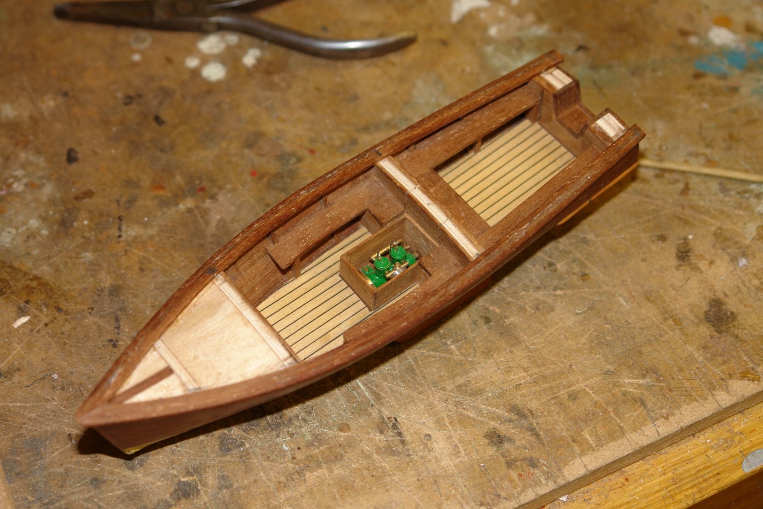
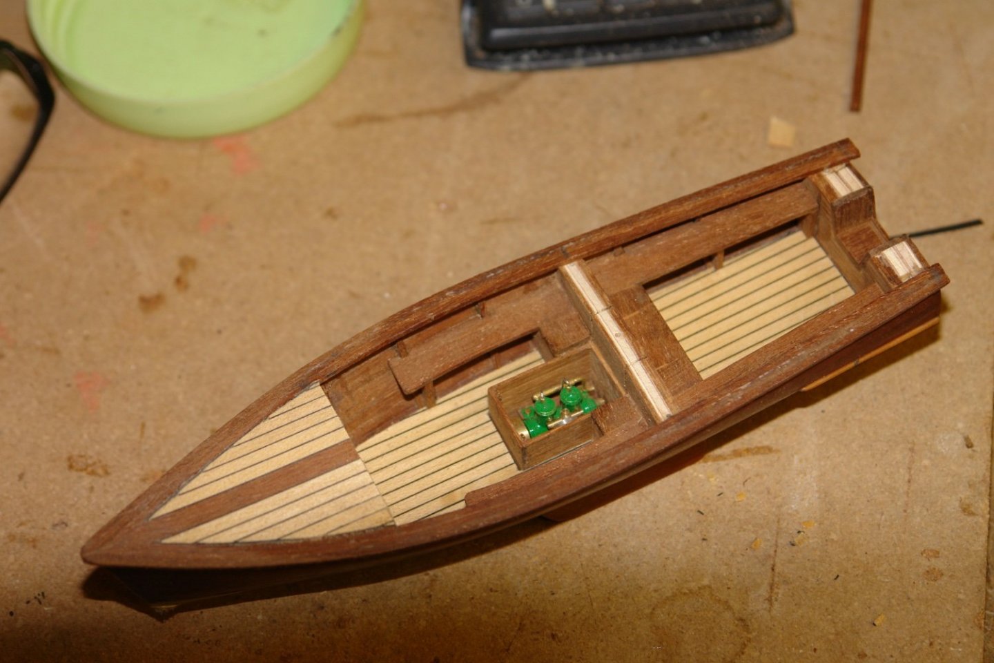
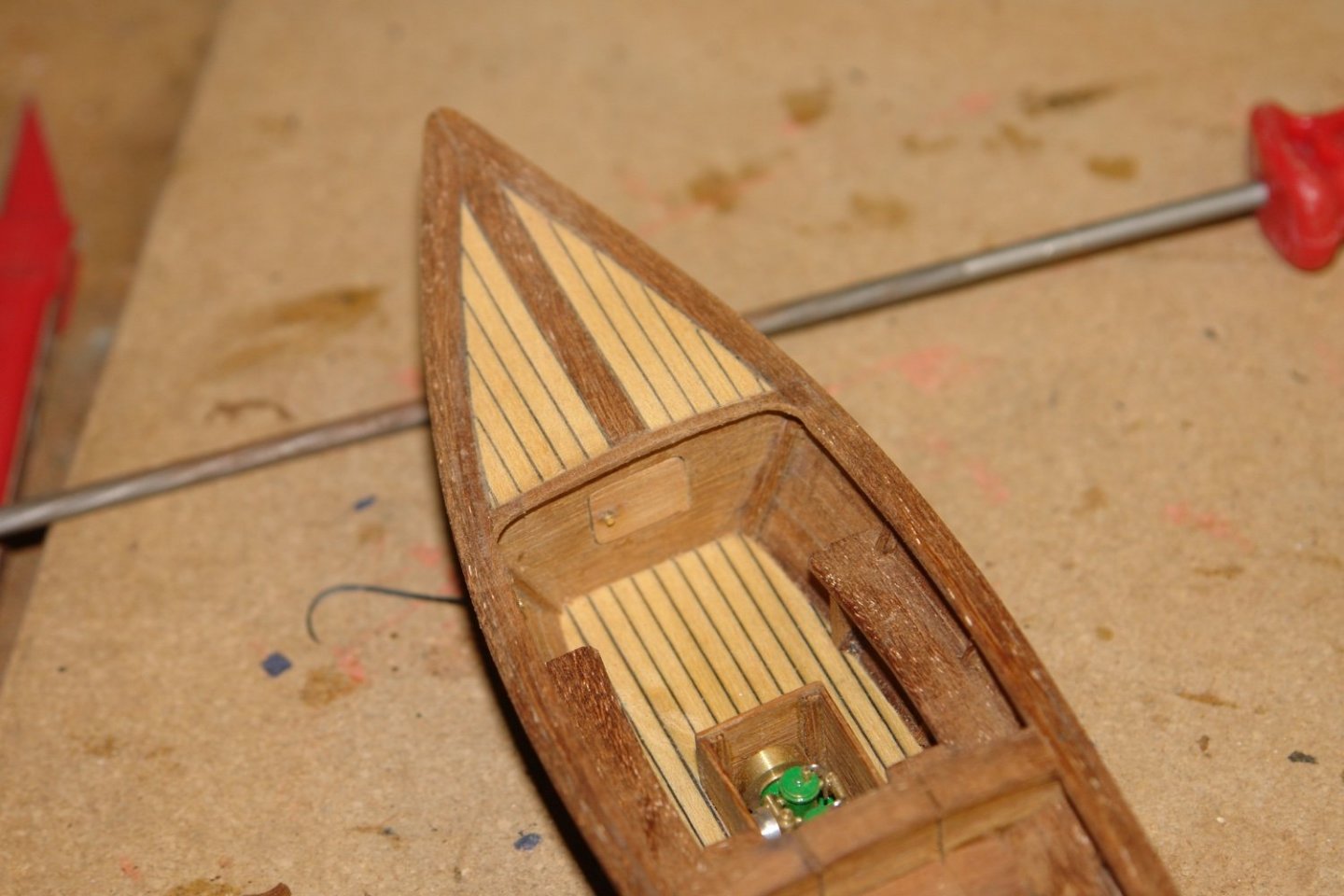
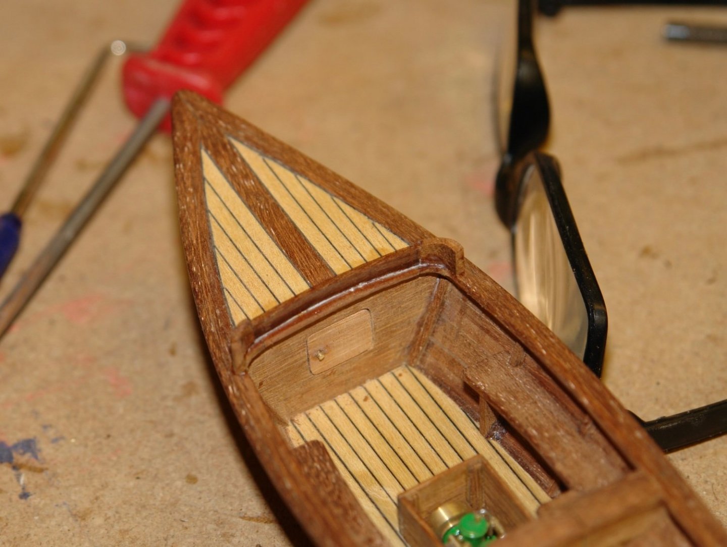
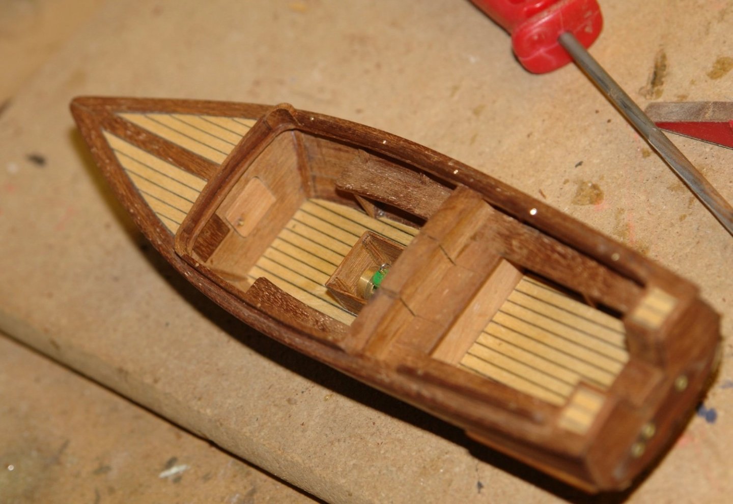
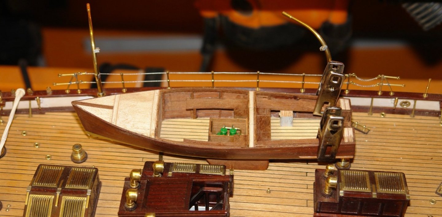
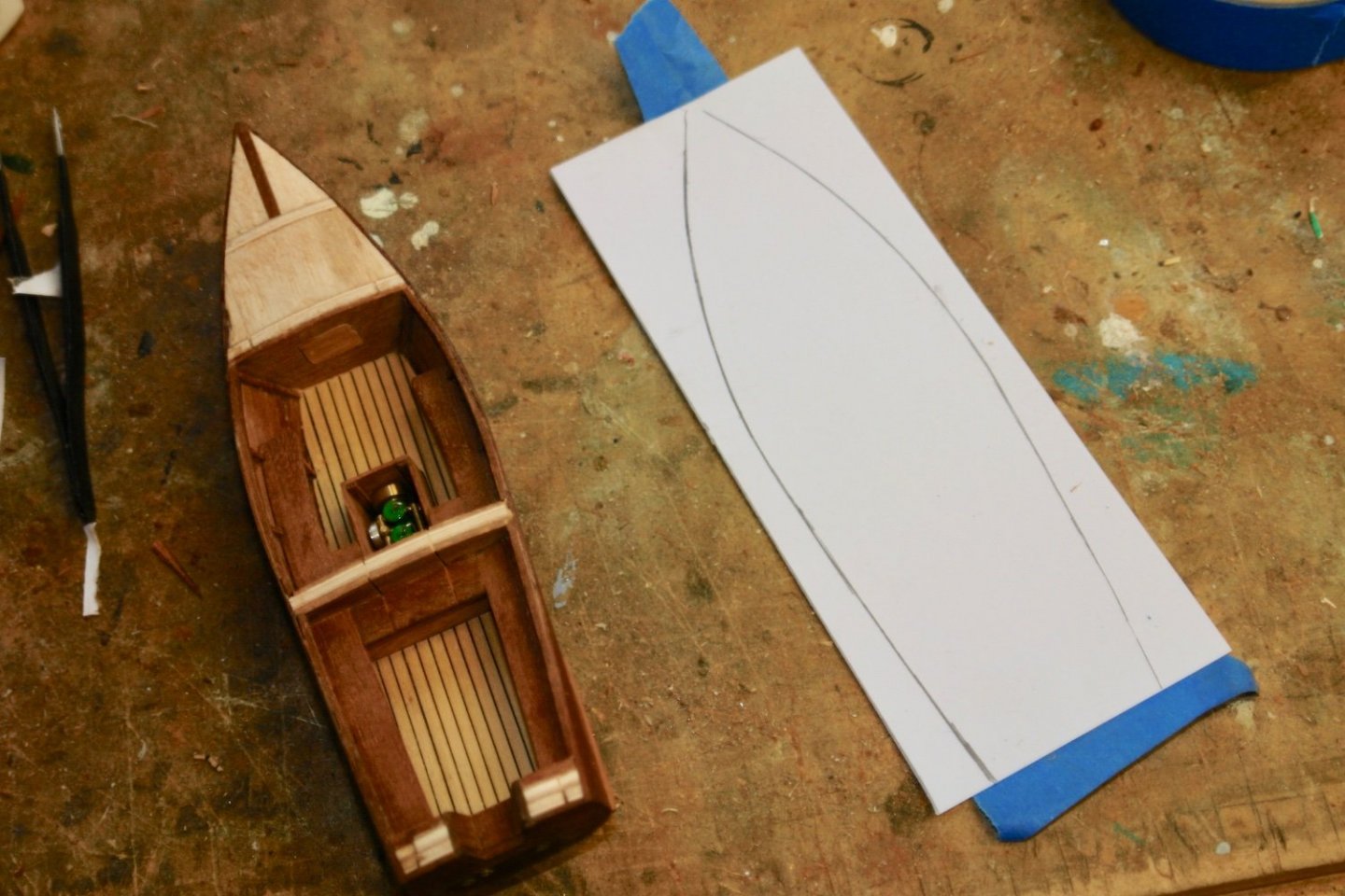
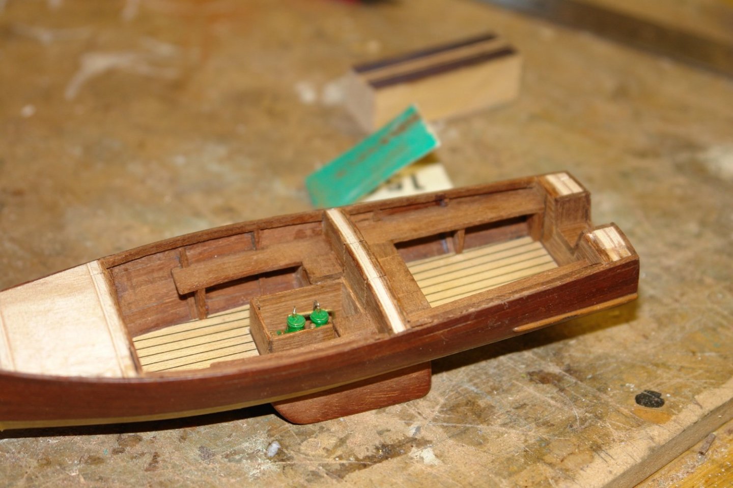
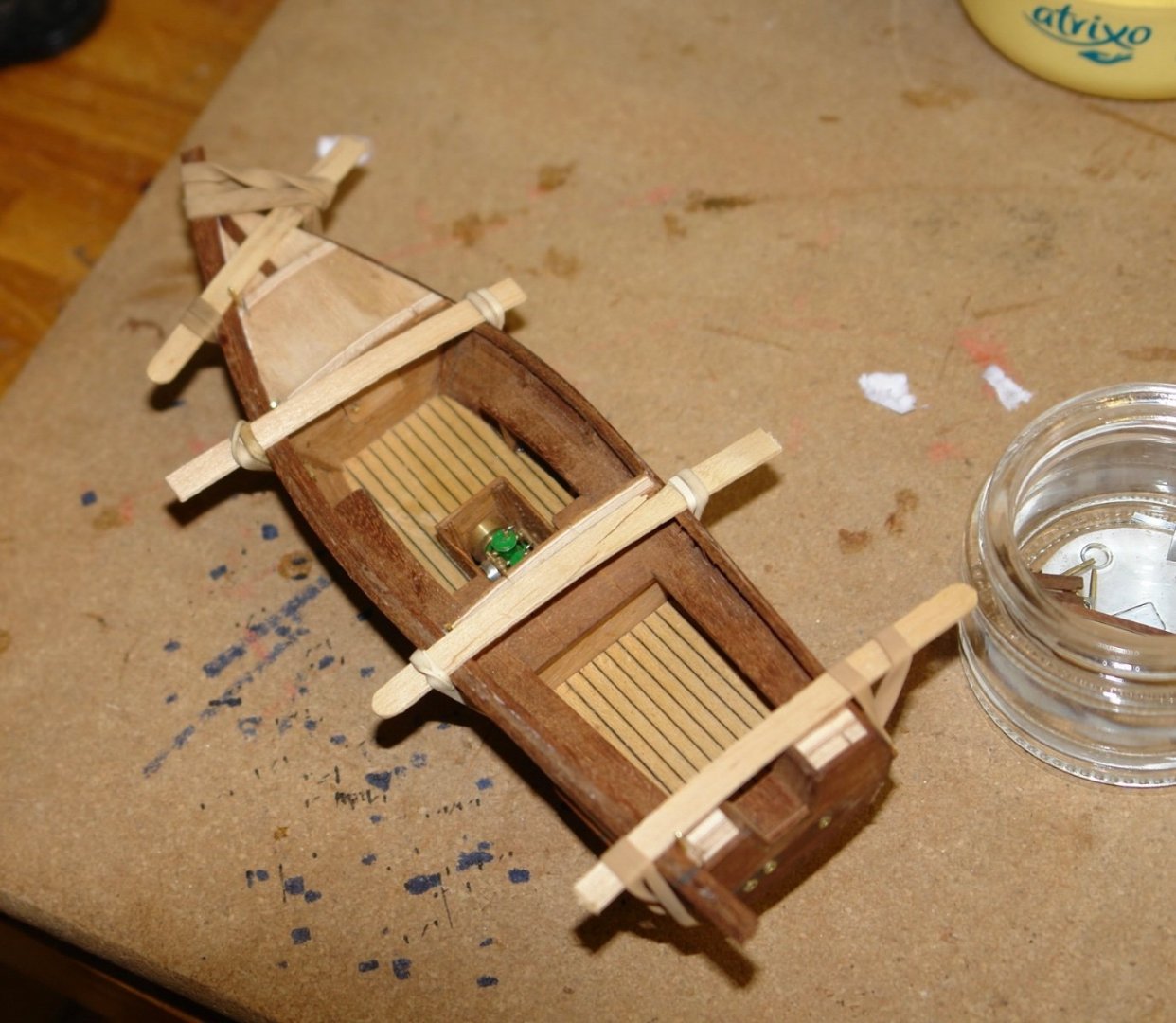
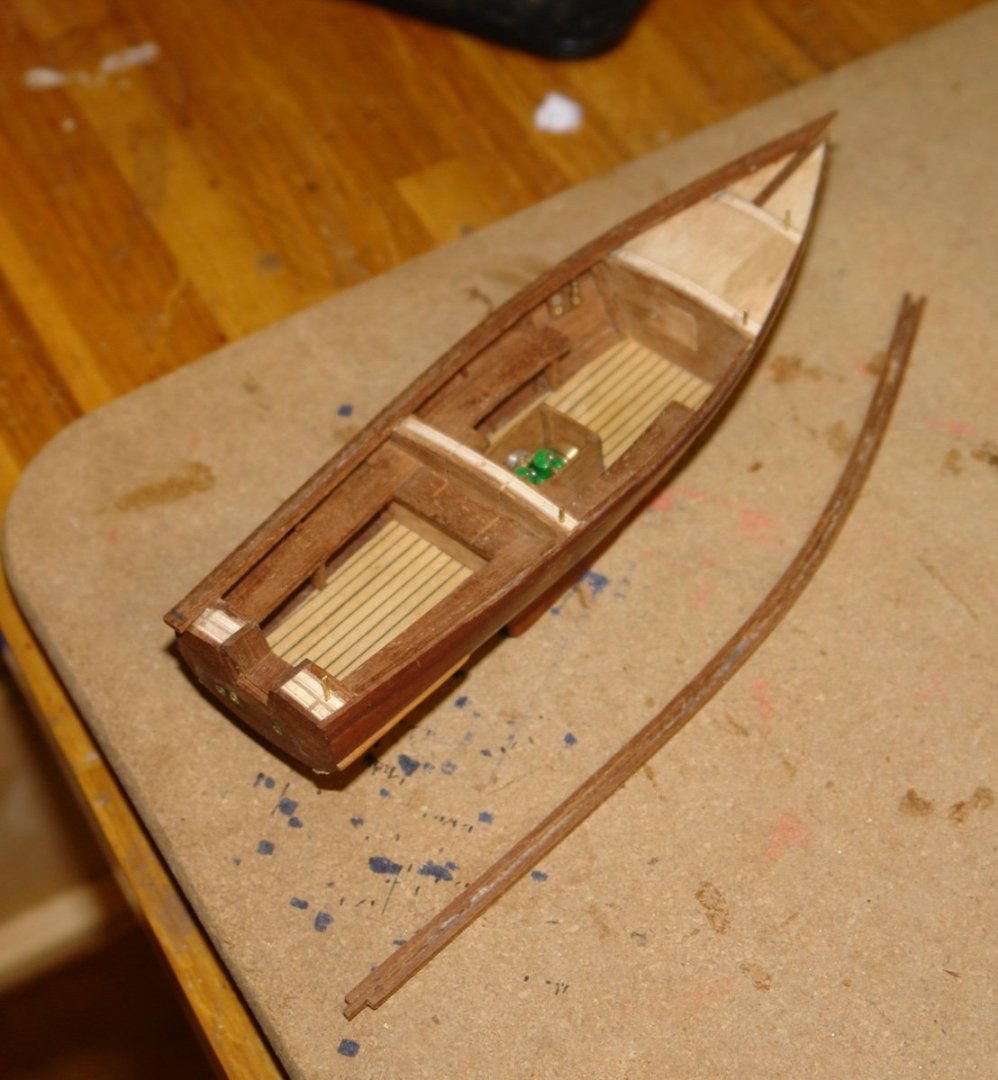
Thank you to all of you who have left recent comments and suggestions and thanks to everyone who has visited and liked my work. I will pick up some of the suggestions in a later post. I have been doing a bit more work on the launch. I installed the aft well deck floor and then made card templates of the aft seating. The templates were used to shape the seats and then these were glued in place with PVA glue. I then moved on to making the cap rails. these could have been cut from solid but I thought it would look better if they were laminated. To get the correct shape I taped a card to the top of the hull and then marked out the shape using the hull as a template. Before mounting the cap rails I decided to install the throttle lever together with the fuel gauge and rev counter.. These were mounted in the location vacated by the boats wheel. Each cap rail was laminated from 3 strips of mahogany, formed to shape over the template and held in place with pins until the PVA glue dried. The rails in the next photo are being checked for shape prior to gluing. Once satisfied with the shape I sanded the surfaces of the rails and then glued them in place using "Starbucks stick clamps" and elastic bands. Starbucks sticks are of variable quality - note the fracture. Once the first rail was dry the second was glued in place. Both rails are now in place so I will move on to the ships wheel next.


-
Eberhard - thank you for the explanation, it must have been quite stressful waiting for the gun to discharge. Also thank you for the link, I wasn't aware of this ships existence. Lovely model work as usual.