KeithAug
-
Posts
3,986 -
Joined
-
Last visited
Content Type
Profiles
Forums
Gallery
Events
Everything posted by KeithAug
-
 I somehow missed the completion. One of the most unusual models i have seen but nevertheless quite charming. Very well done.
 -
A picture is worth a thousand words. Cairo looks amazing. Workspace is a 5/10 which is better than my usual score.
-
Brian Re - I happened by the Admirals craft room where she was hard at work making stencils for T-shirt on her Cricut. I need one of those. Must get my wife into making stencils for T shirts then I can buy her one for Christmas. Also I am always amazed that the photographs of your work space and model never have a speck of dust on them. How is this possible?
-
Hakan, Your off cuts bin looks a bit like mine - wood, broom handles both metal and wood, bit of tubing etc, etc. You have reminded me - i musts sort it out. Nice progress on the build - all looking very neat.
-
Thank you for commenting Michael, Richard, Pat, Keith, Druxey and Eberhard. Also thank you to everyone who has visited and liked my work.
-
Very nice little restaurant on the east coast of Just Van Dyke i recall. I was there in about 2005 - generally very nice but we found the sailing was a bit constrained by the closeness of the islands. Great snorkelling at RMS Rhone and at the Baths on Virgin Gorda. On the negative side we found the BVI's a bit over run by noisy catamaran gin guzzler types.
-
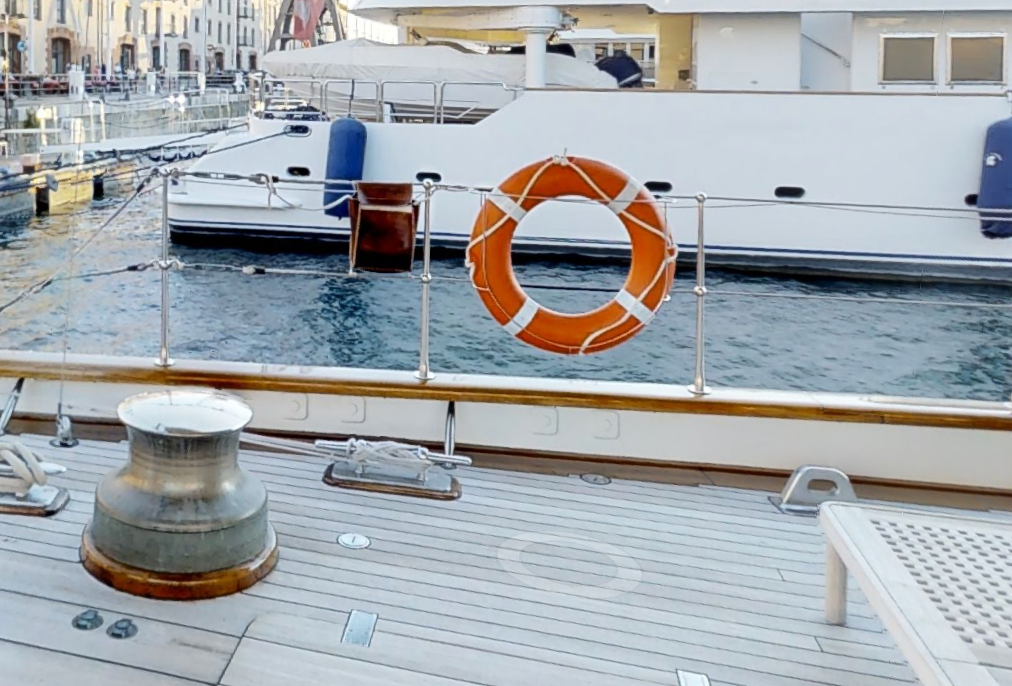
Eberhard, Sometimes they sail with it on deck. And sometimes they don't. They also seem to spend a deal of time sailing with it replaced by a dinghy. It must increase the C of G and reduce the metacentric height (while also increasing the starboard list). My guess is they take it with them on position cruises and then land it and rely on the dinghy while racing or cruising within the local area. I will also be making the RIB which sits on the port side.

-
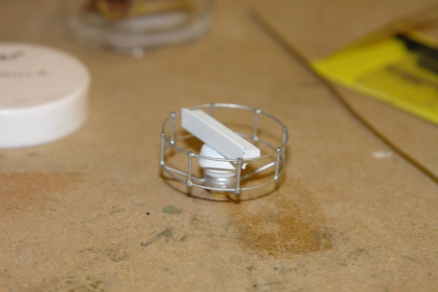
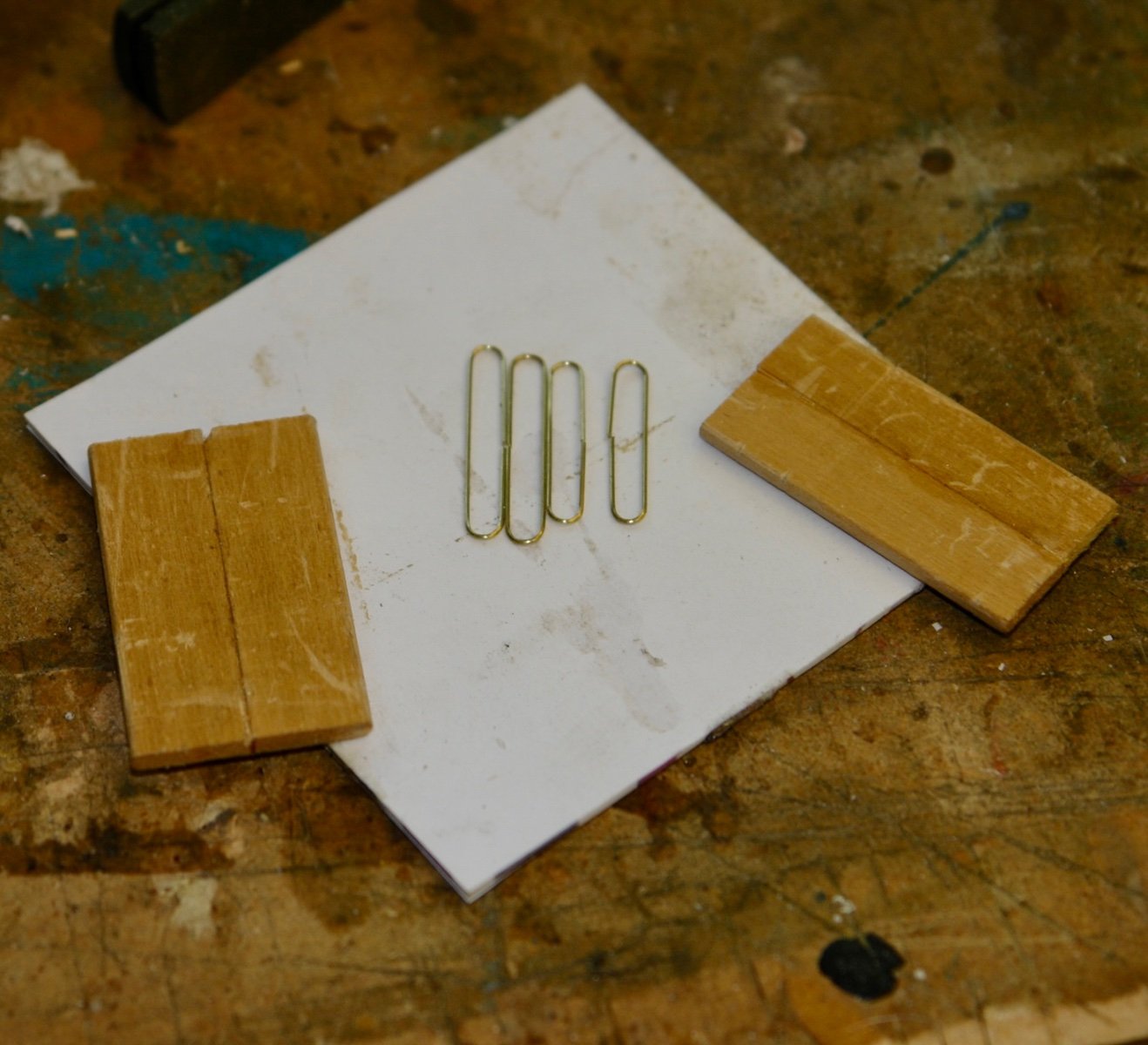
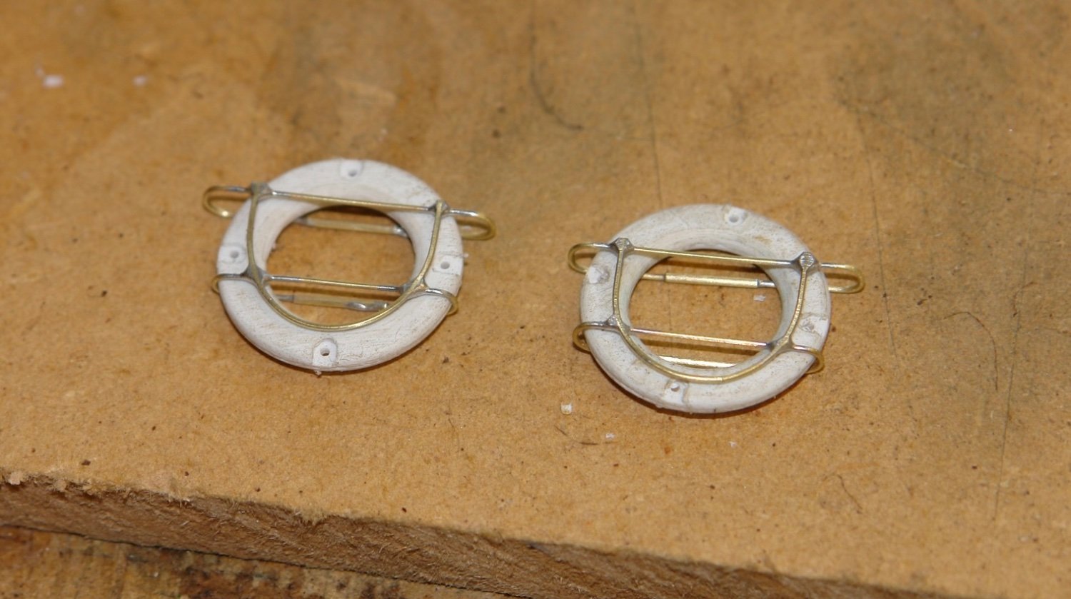
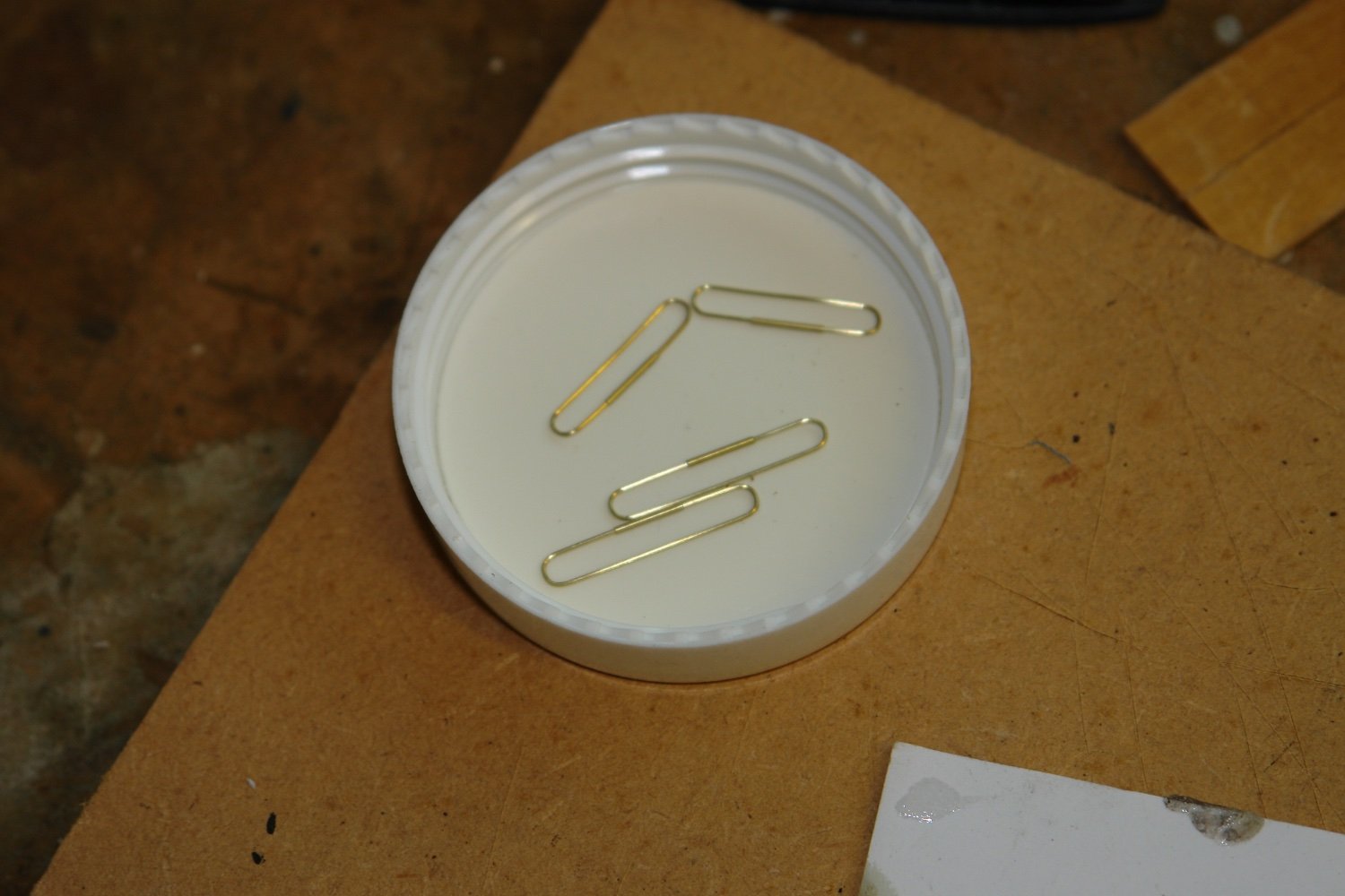
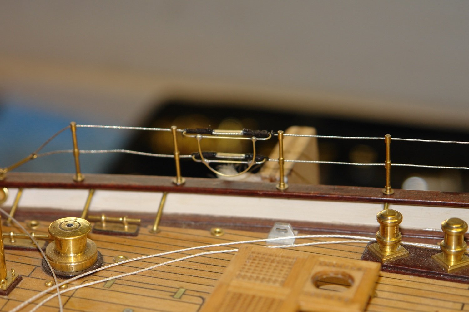
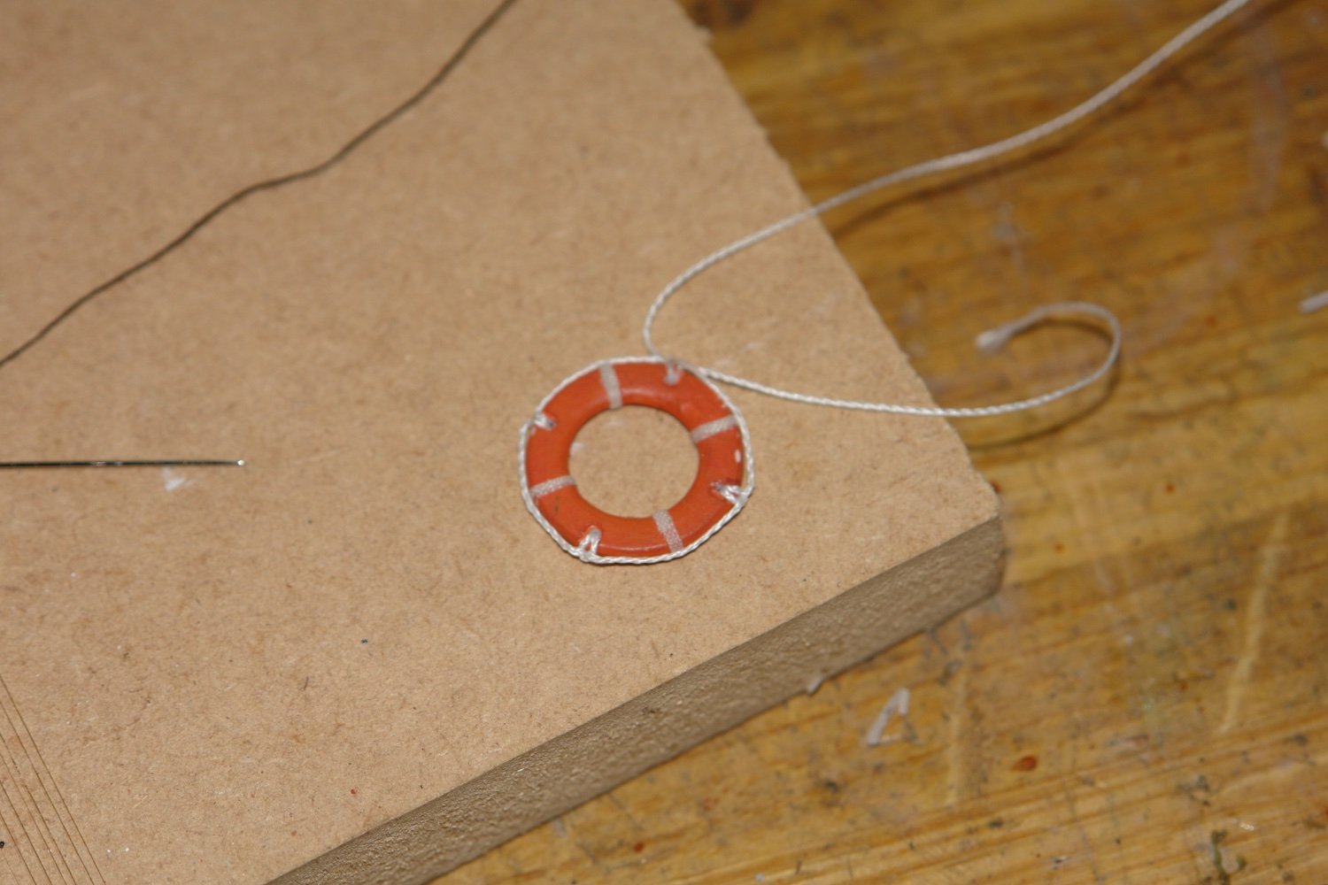
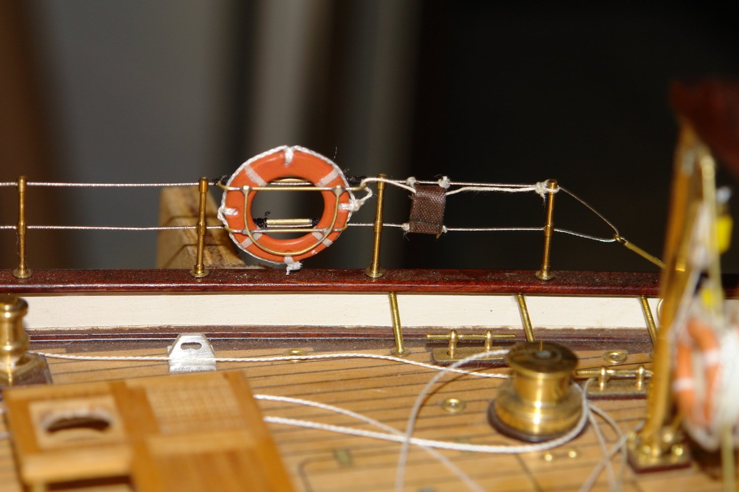
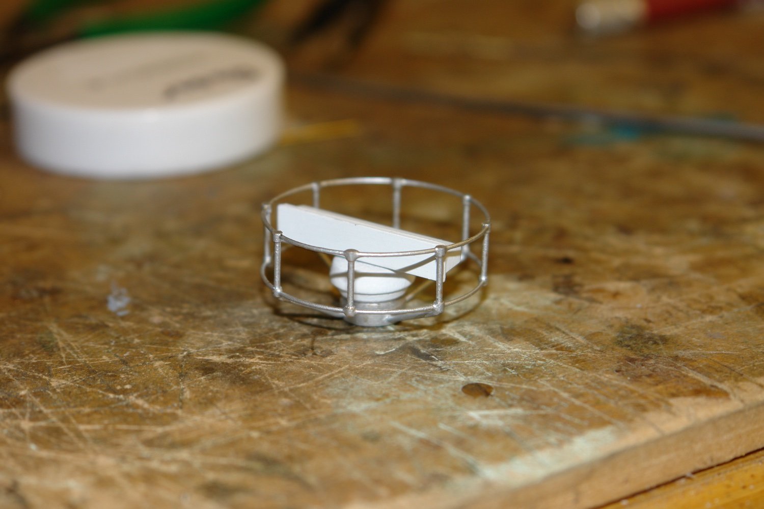
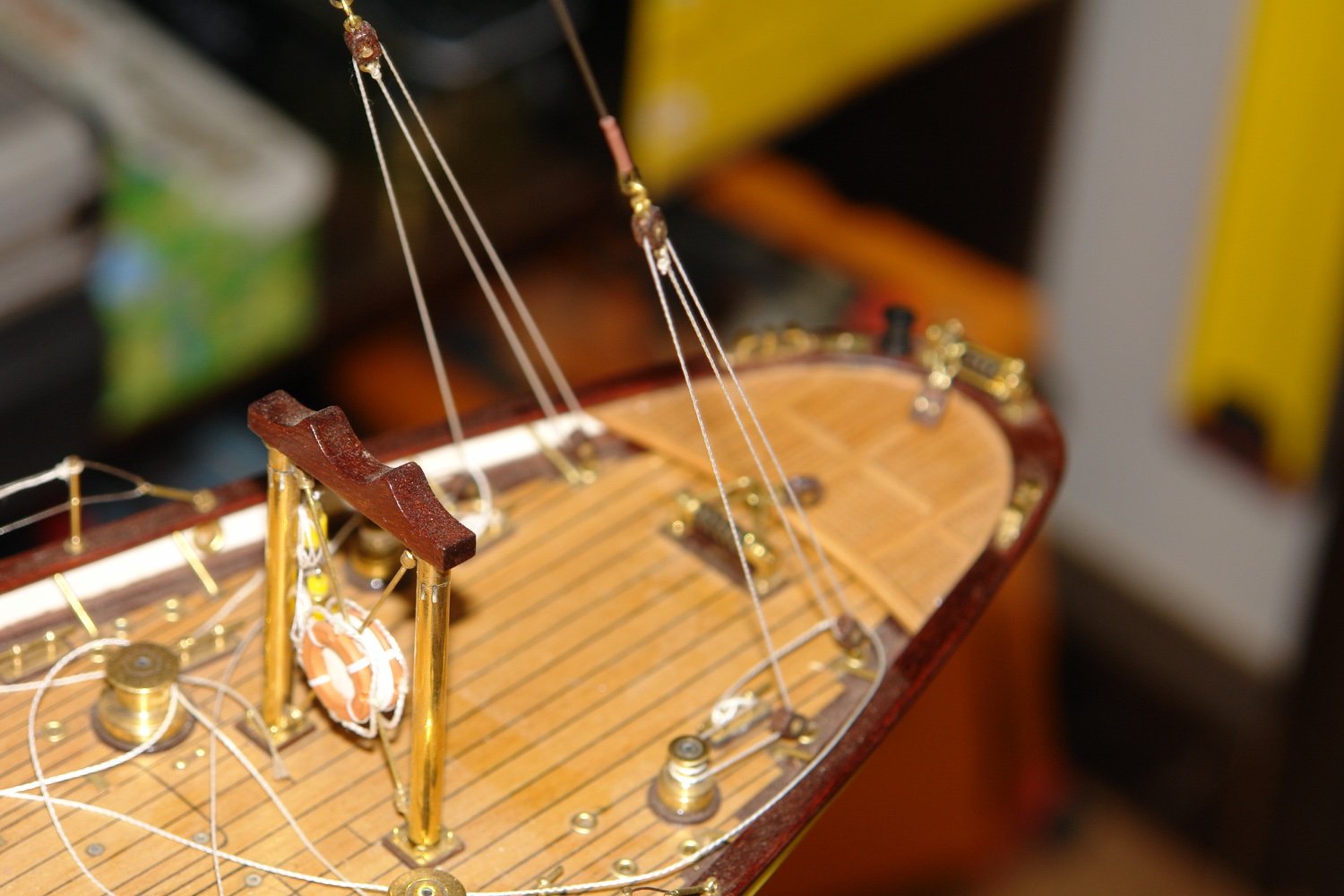
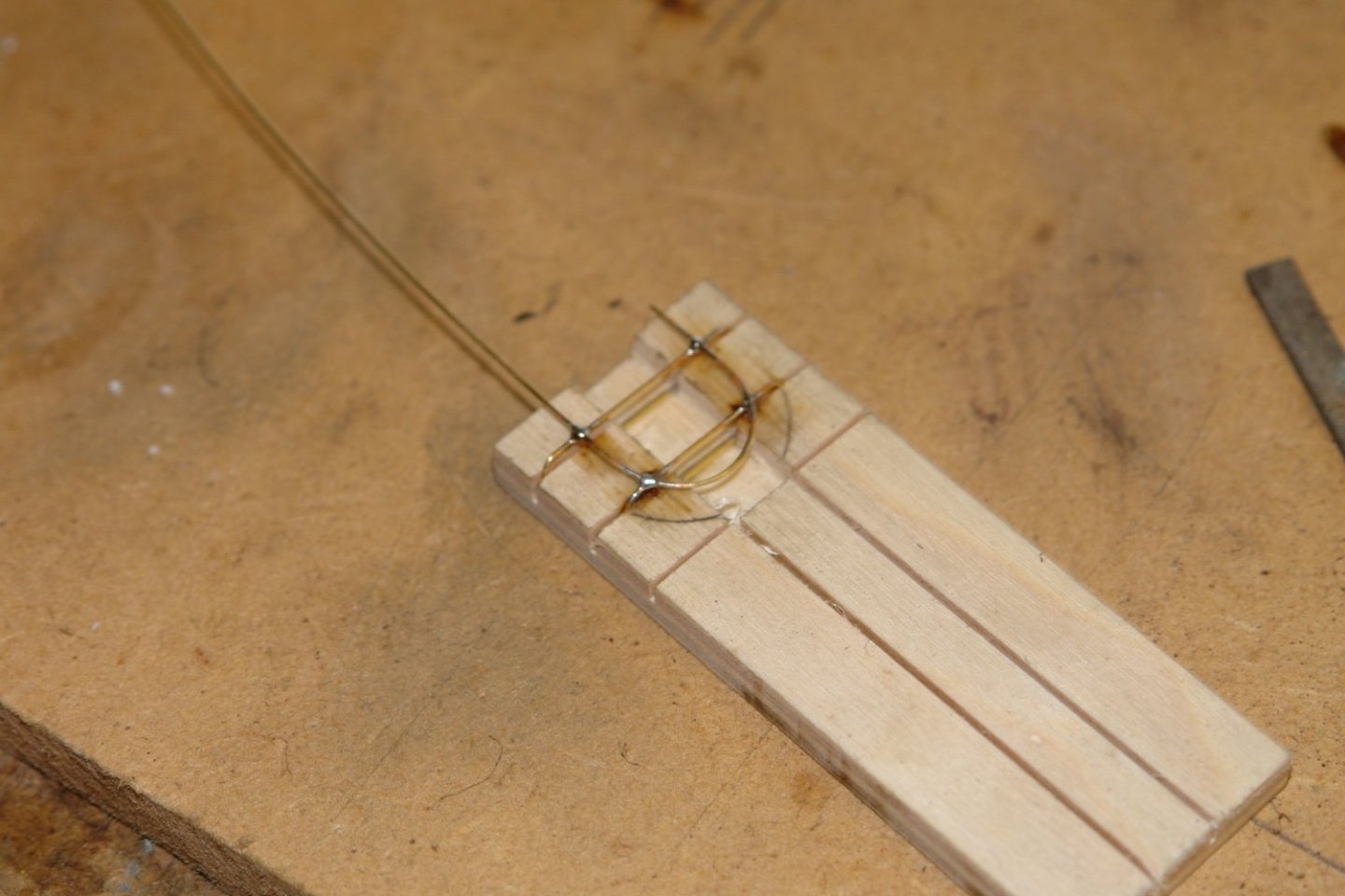
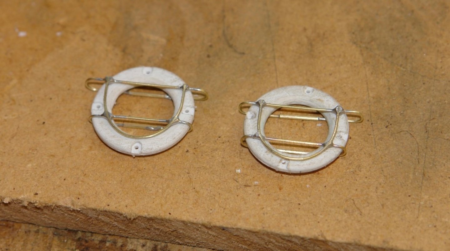
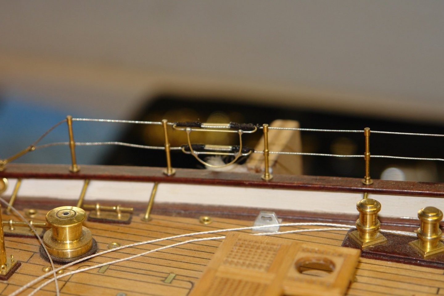
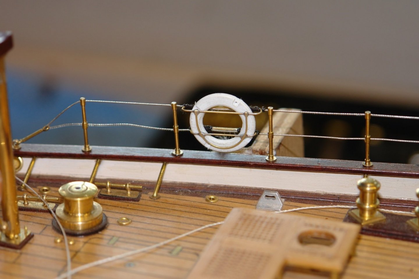
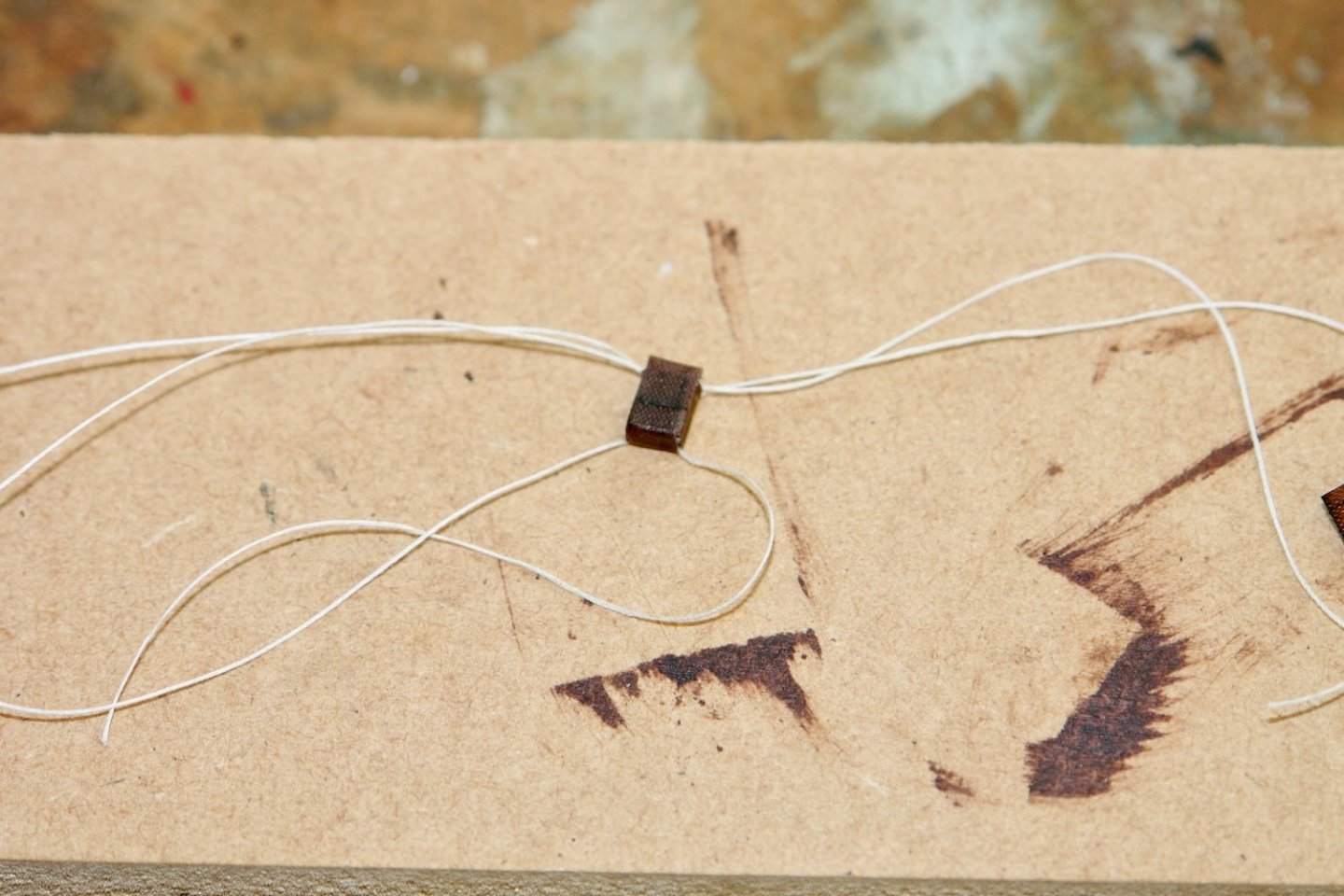
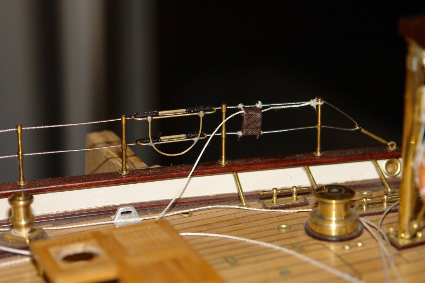
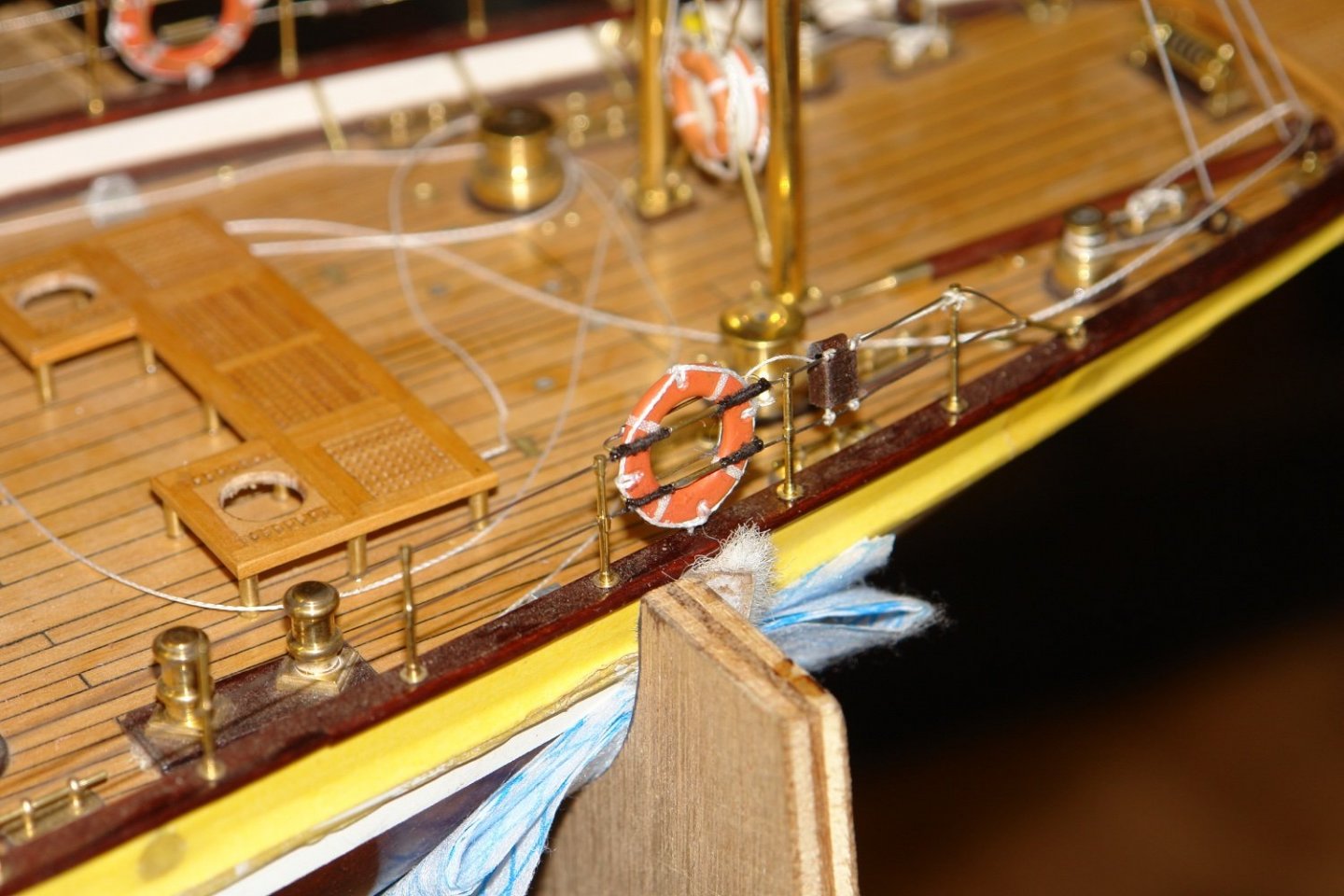
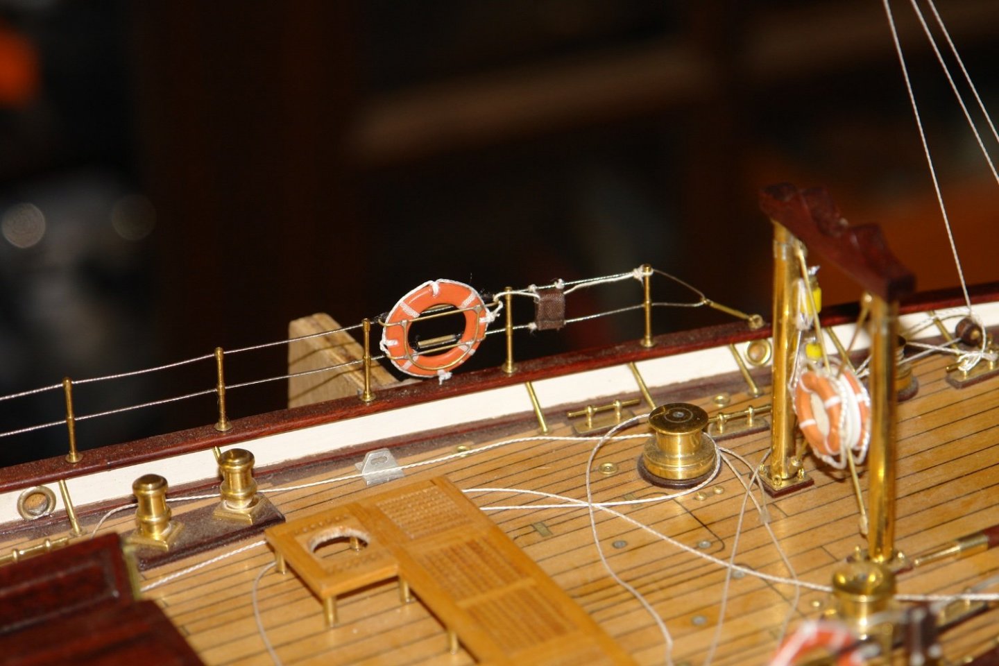
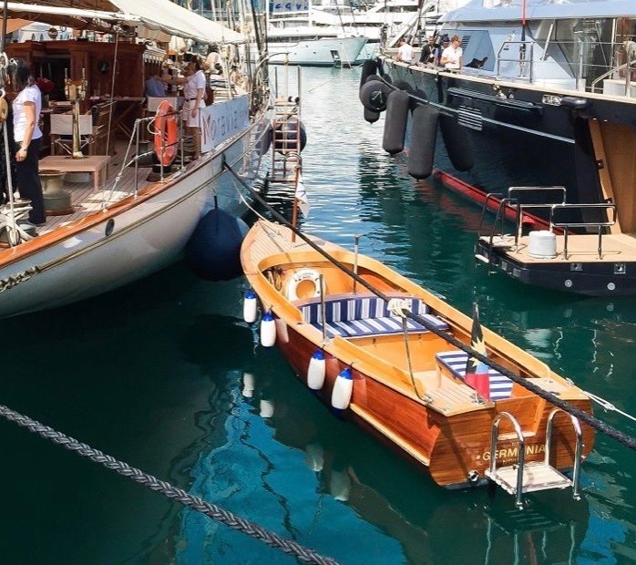
I continued with the life rings as per the photo. It isn't very obvious from the photo but the life rings sit in wire baskets. The leather pouch holds the line and this is tied off to the rail. I started making the basket from .025" wire. I made two formers from scraps of wood and used these to bend the the "hoops" which retain the life ring. The free ends of the hoops were connected by micro-bore tubing. I then slotted a piece of plywood to create a soldering jig and I bent the wire which joins the hoops. The hoops and joining wire were then soldered together. I then tested to life rings in the baskets. The baskets were then lashed to the guard rails using black cotton. The pouch is quite small so I cheated and formed it round a piece of scrap wood cut to size. Sail tape (painted brown) to simulate leather was then stuck to the former with 3 lines added to give 6 ends. 4 lines attach the pouch to the guard rails and the other two attach to the life ring and the rail. I painted the life rings and added the reflective strips and the grab ropes. The rings were then pushed into the baskets and the life line was tied off. I think I am going to make a start on the launch next.


-
Eberhard, When i looked at the picture i wondered if you had made the chain - i thought you had perhaps gone mad and was somewhat relived to hear you had bought it. Thanks for the suppliers details - added to my tools and materials list.
-
I know how you feel. At the end of cutting the frames for a particular build I’m getting quite good. I then put the saw away and don’t use it for 3 years until I start the next build. I’m then back to square 1.
-
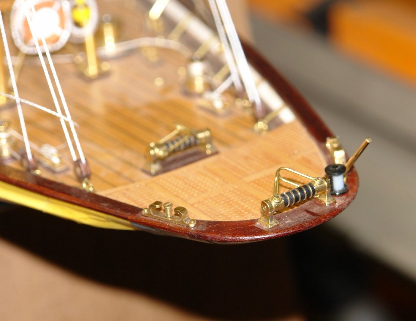
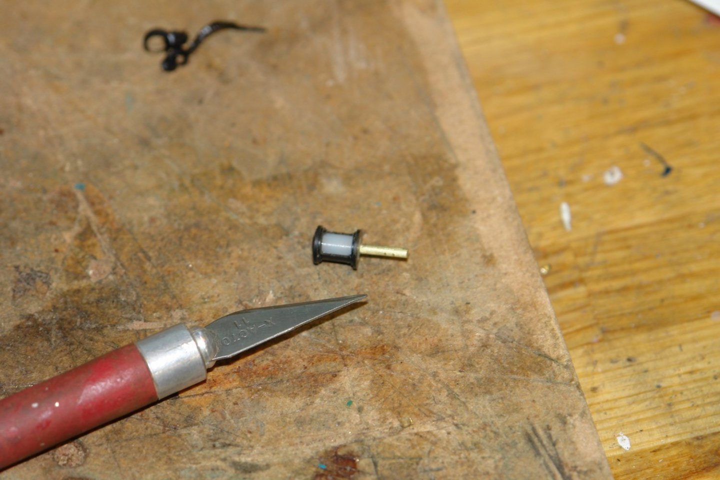
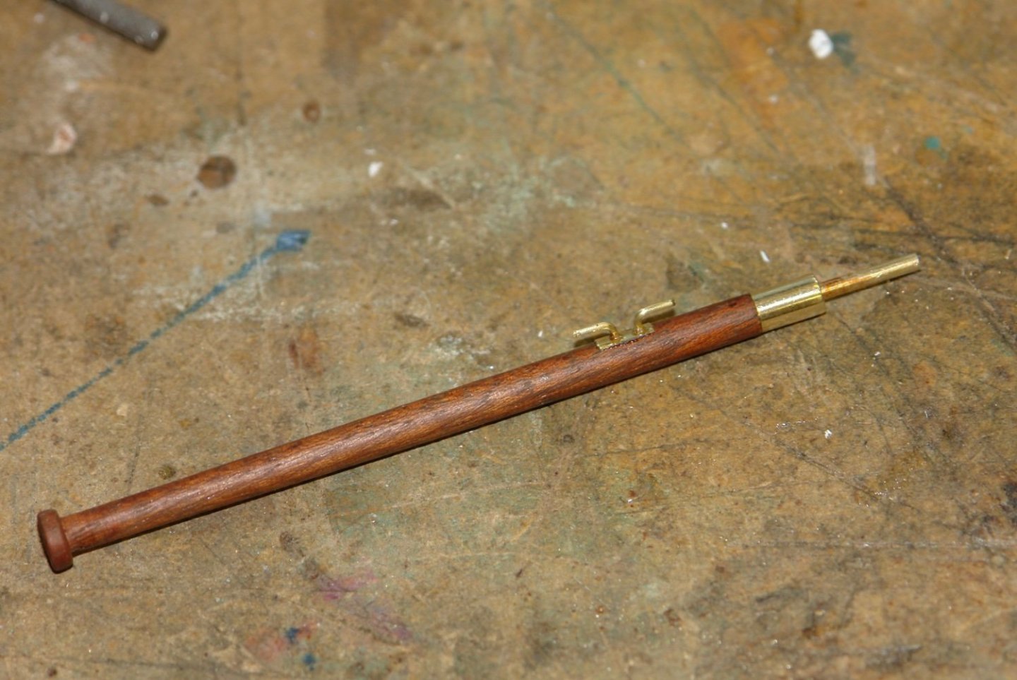
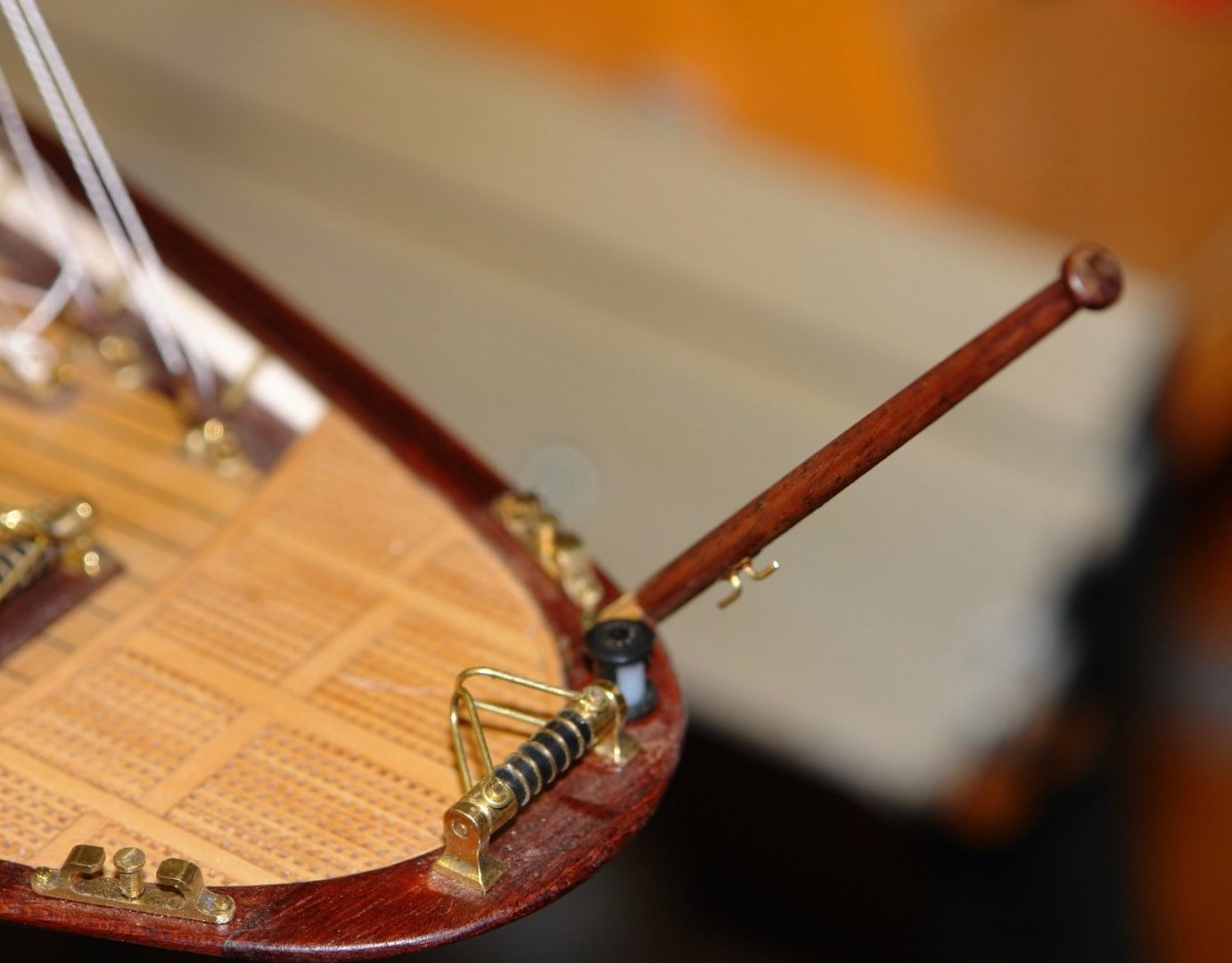
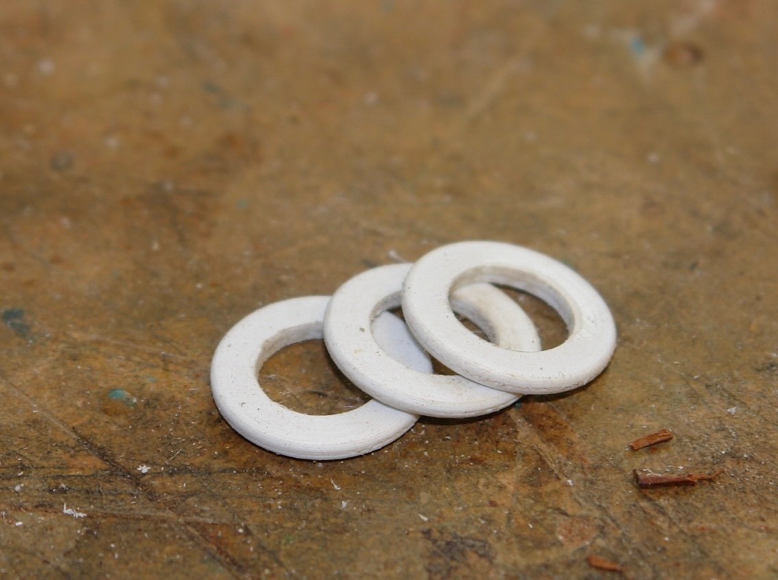
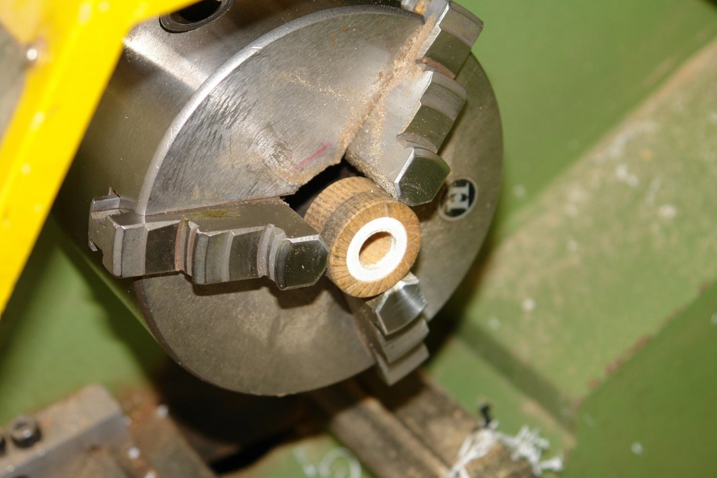
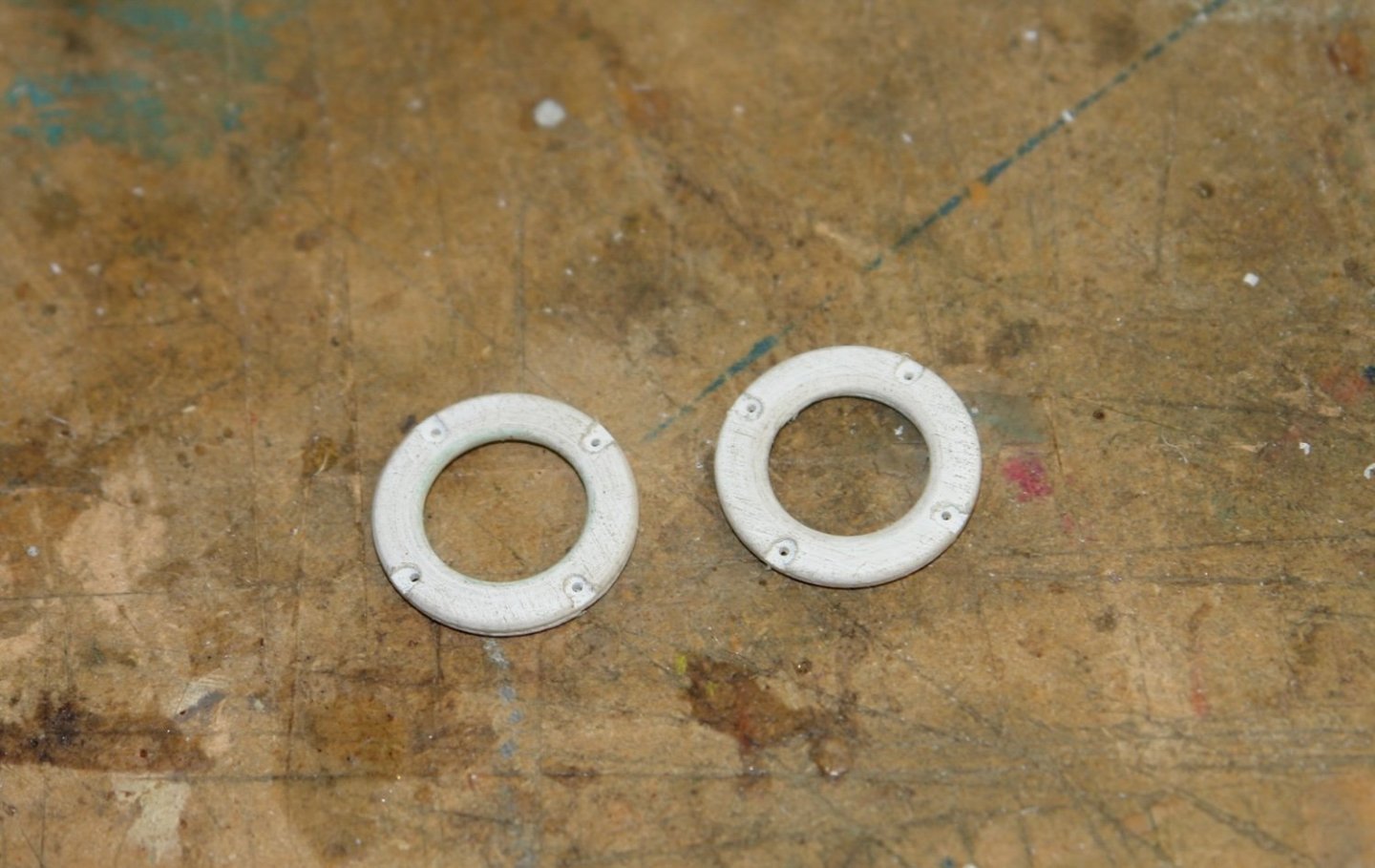
Thank you Keith, Gary, Pat, Steve, Veszett, Maker, Andy and Michael and than you everyone for the visits and likes. I haven't made a lot of progress in the last week, house guests took their toll and I spent some time fitting a DRO to the mill. I did a bit of turning to make the stern light. I then made the flagstaff from a bit of mahogany dowel with brass fittings. I have decided however that it looks a bit heavy so I will thin it down a bit. The stern rails have 2 life rings attached. These are of the larger type - 30" external diameter (.83" at scale size). I glued 2 pieces of .040" plasticard together, drilled the central hole and then turned and shaped the outside diameter. I needed to shape the inside diameter so I machined out a bore in a piece of wood and pressed the rings into it. I then shaped the bore. With the rings still in the wooden jig it was mounted in the mill and the notches were cut out and drilled to take the grab rope. Not much progress but the guests have now gone so things should improve.
-
impressive planking to both the deck and hull. Well done.
-
A lot of members have faced these challenges. Post a few pictures and I'm sure you will get a lot of useful advice. Build looking good.
-
Very complicated paint job. I think you should have said "I made the deck from teak" no one would have been any the wiser.
-
Looks very interesting, hopefully after 28 years progress will now be a little more rapid.
- 15 replies
-
- 3
-

-

-
- lumber hooker
- Oscoda
- (and 4 more)
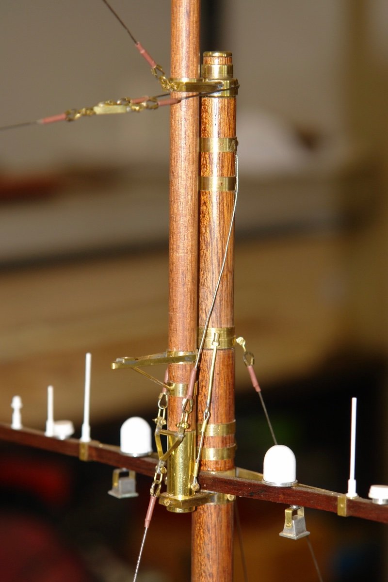
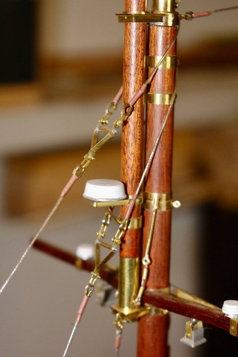
-
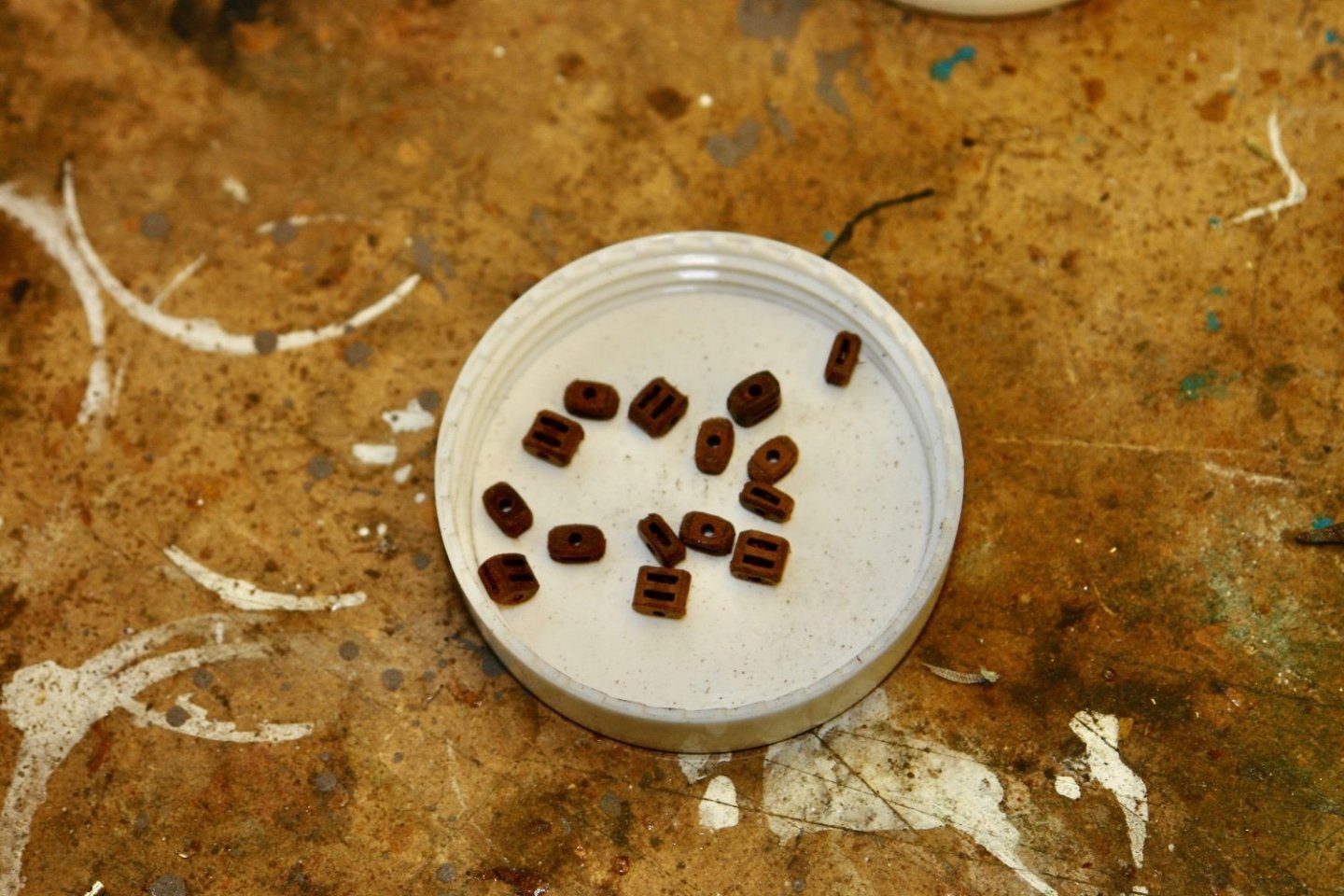
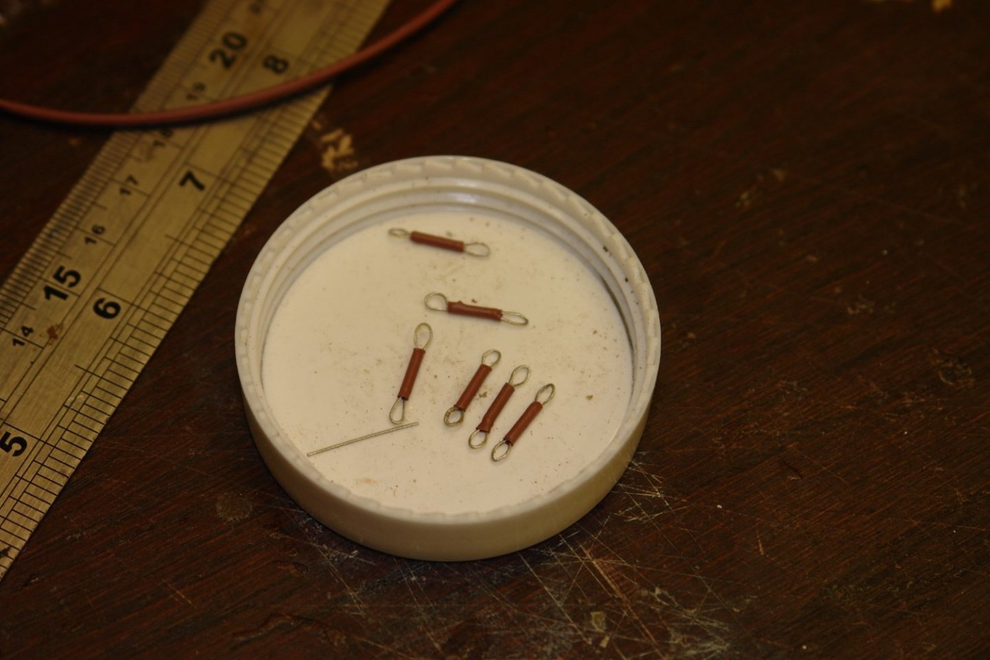
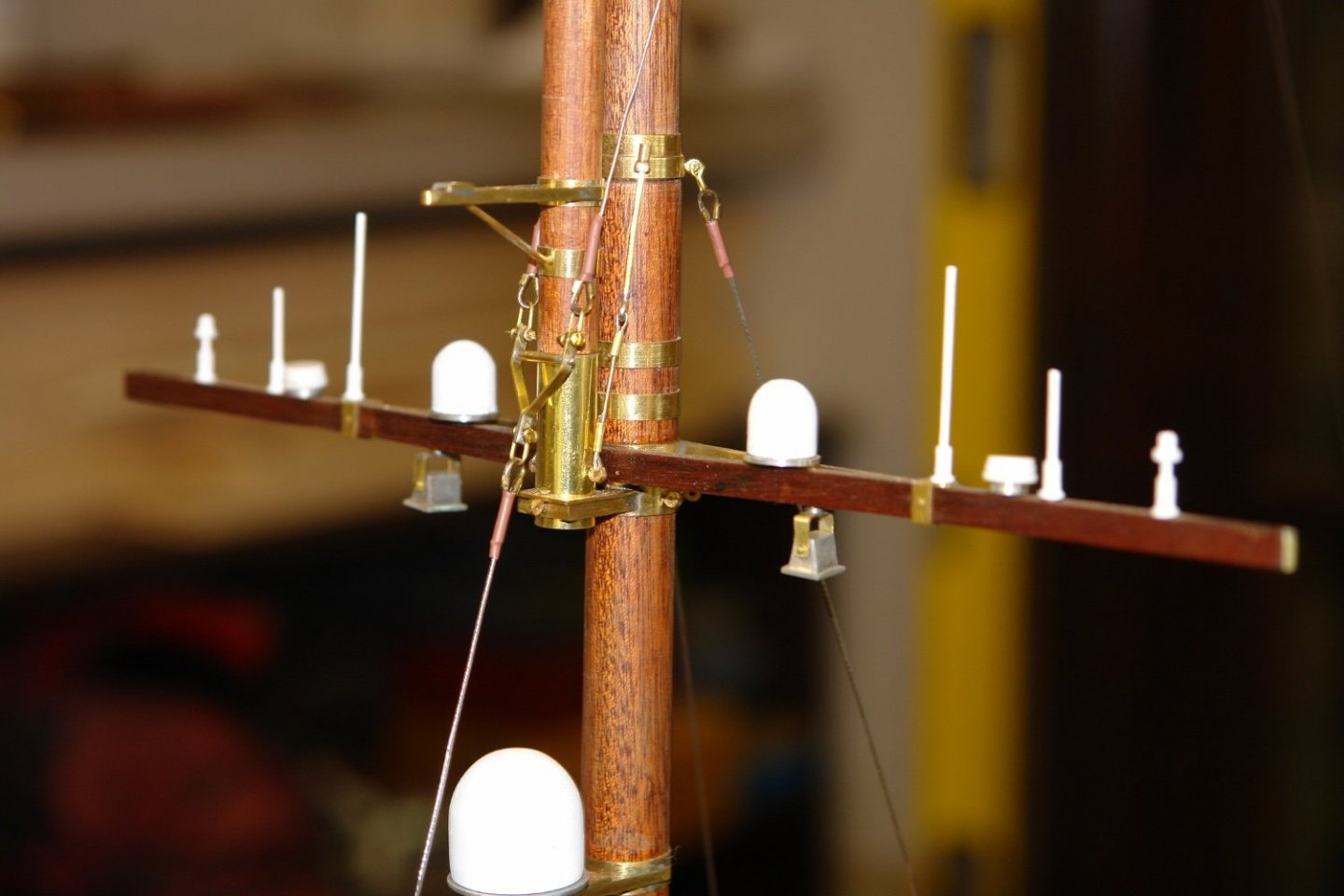
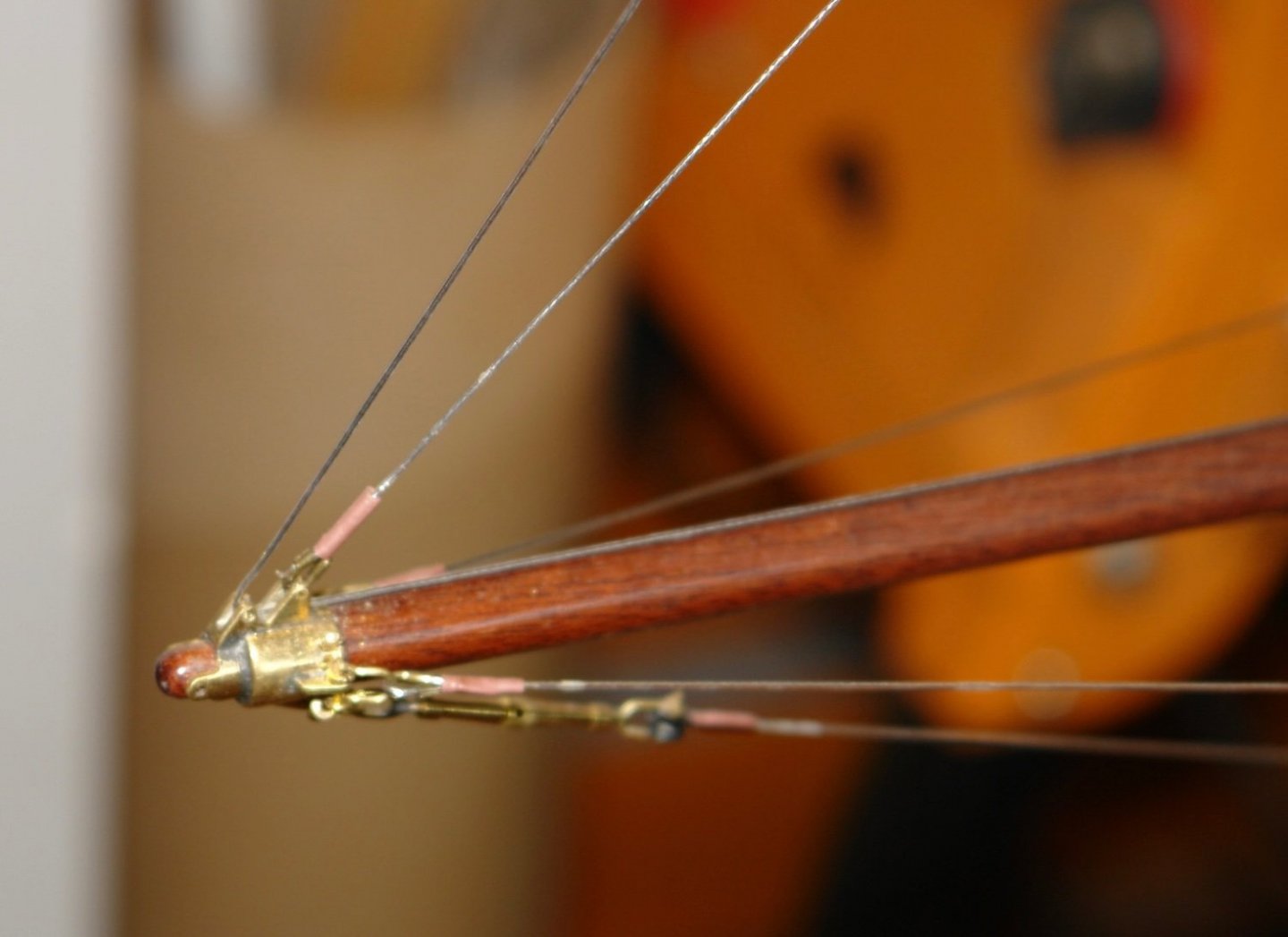
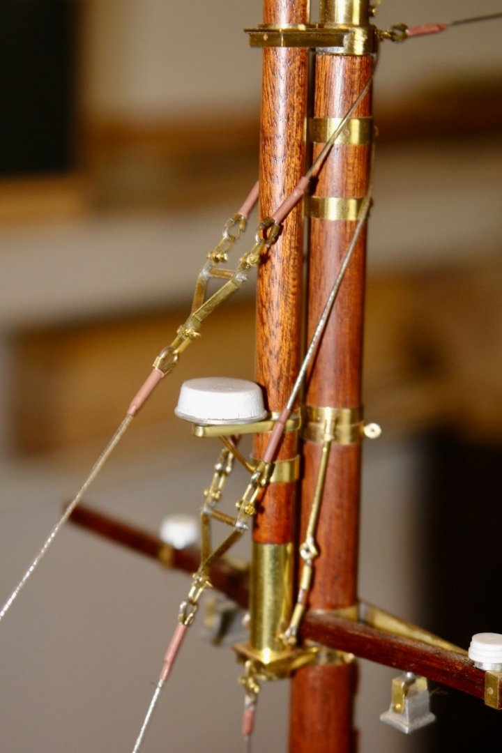
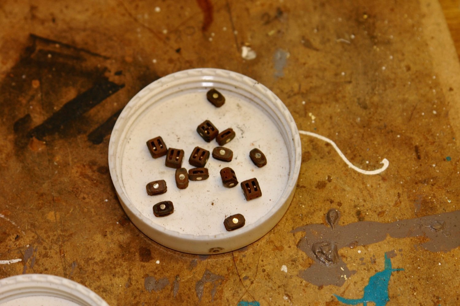
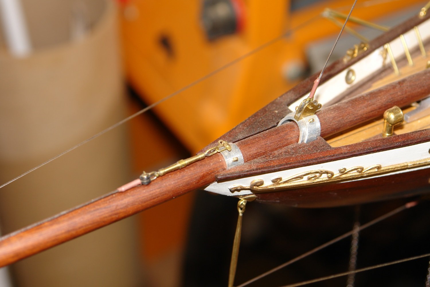
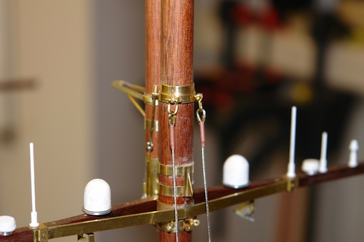
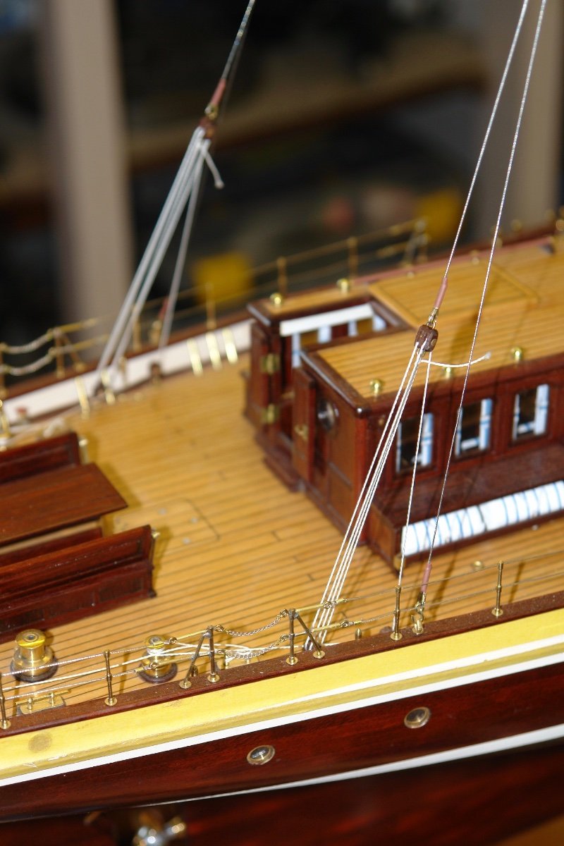
Thank you Eberhard, Druxey and Richard for commenting - also thanks to everyone for the likes. Most of the last week I have been working on the fore to aft rigging but I did start by fixing the radar (thank you Eberhard) - before and after shots below:- I also needed a number of medium sized bocks for the running back stays (2 pairs), so I spent a day making a few. I also made a few strops which I then realised were not needed - but never mind they will be needed later. It find it is almost impossible to take good photos of overall rigging so I just took photos of specific areas. Getting the tension correct in all stays is a bit of a trial but in the end I managed it - the next photo shows the flying jib stay tensioner. The jib and flying jib stays were also mounted at this stage. The top of the jib and fore stays are shown in the next photographs. I then moved to the stern and installed the pair of running back stays for the lower main mast. The photo shows the top attachment. Followed by the bottom - both are tight at this stage but the leeward side will be slackened off later. Then the main topmast running back stays were rigged. I then rigged the brace for the main mast. (It braces the top to the bottom via the dome (satellite coms?) bracket. The stays joining the fore and main masts were then rigged. I have a few more deck fittings to make, life rings, stern light, and flag staff. I will have a go at these next.