KeithAug
-
Posts
3,980 -
Joined
-
Last visited
Content Type
Profiles
Forums
Gallery
Events
Everything posted by KeithAug
-
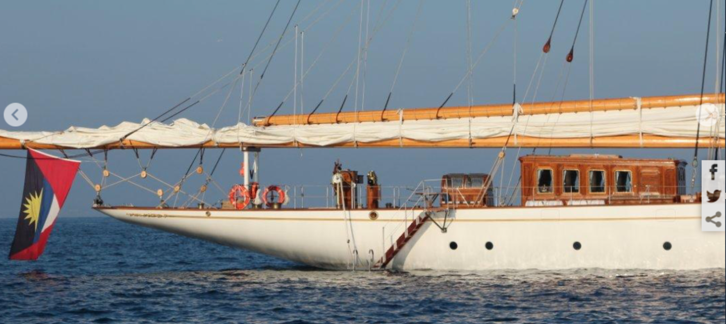
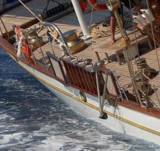
 The hull is looking rather fine, particularly the plating details. A bit of scale indication on the shackles, blocks and hooks would be helpful. Including a match or something similar might be useful.
 -
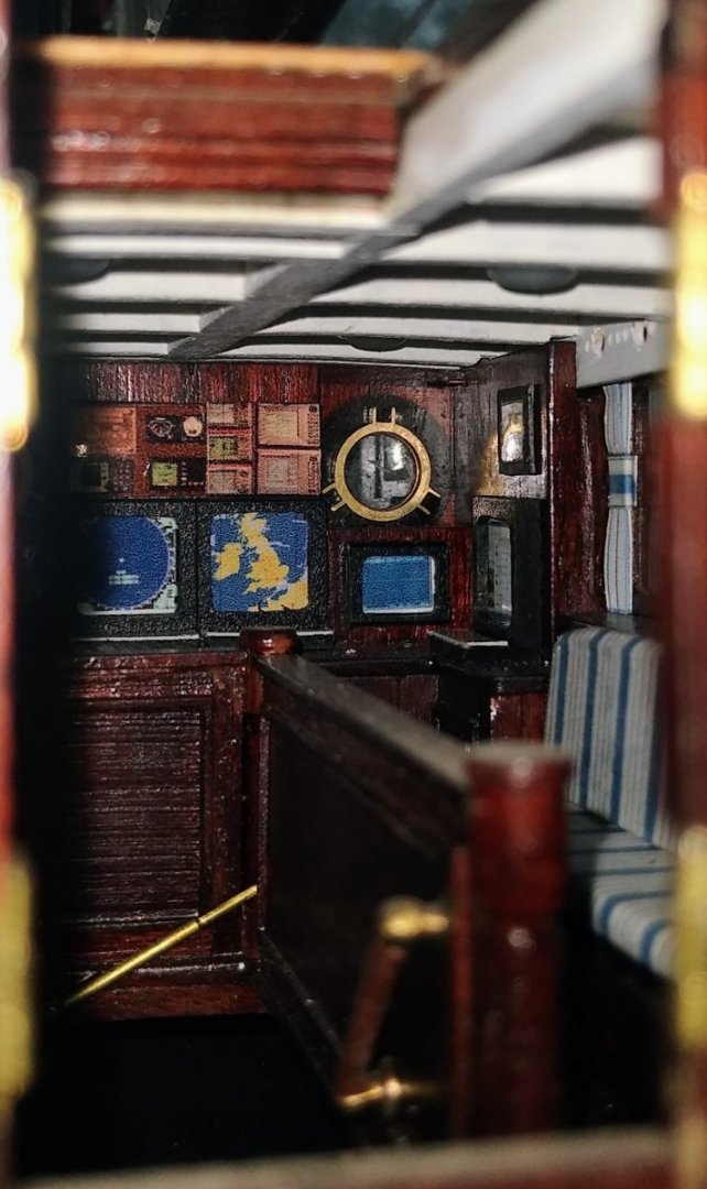
I was messing around lamenting that I couldn't see much of the main cabin interior though the door, so I pushed my very old and poor quality phone camera up against the door and took a photo. The low quality of the image seems to me to have helped the "atmospheric nature" of the image. i really liked the computer screens, keyboards and instrument panels. I also liked the roof beams with the lights peeking out, but most of all I liked the reflection in the porthole window. Sometimes it is good to take a backwards look.
-
The small boats turned out rather well. i must remember that method.
-
Nice job Dan, particularly the detailed description of the process.
-
Rob. The rigging is truly impressive. It must be either a labour of love or a penance. I do admire your dedication to the task and the structured way you approach it.
-
Was - The brass work is all looking pretty smart - are you planning to paint it?
-
HMCSS Victoria 1855 by BANYAN - 1:72
KeithAug replied to BANYAN's topic in - Build logs for subjects built 1851 - 1900
Pat, is it possible that the fore support for the boom has a pivot to allow the aft end to swing out supported by the topping lift, thus allowing the boats to be launched between the boom and the hull. It seems to me that this would be the simplest and quickest way of completing the exercise, but then again what do I know🥴.- 1,013 replies
-
- 3
-

-
- gun dispatch vessel
- victoria
- (and 2 more)
-
Druxey. I did try it but it just produced a wavy edge and a more random distortion. In the end I decided a more regular distortion would perhaps work better. In 1969 at the age of 16 I started work as a Rolls Royce Engineering Apprentice. The first year of training included 32 weeks of manufacturing training in the Apprentice Training School in Mickleover Derby. Royce's lathe was in the corner of turning training bay. It was immaculately maintained and had a polished brass plate explaining its history / ownership. If you were very good (or lucky) you were allowed to use it. I must have been lucky. My everlasting memory of it is that it was like an alter at which the lucky few got to worship.
-
Hi Brian - yes it is true that many areas of the world have much higher temperatures than our little heat wave. Having mild winters and summers does have advantages but the main disadvantate is that very few homes in the UK have A/C. My brother in law who lives in Phoenix Arizona has his A/C set at 25 deg which is a bit lower than our lounge which was registering 35 deg. Steve it was a bit of media hype, the fires were pretty limited especially compared with the wild fires being experienced in other parts of the world and of course the emergency services dealt with them reasonably well. Fire brigades here prioritise preservation of life (including their own) above the preservation of property and some media types choose to ignore this when dramatising the situation for televisual effect. The main issue over the hot spell was that in the UK people don't normally have to be mindful around parched ground and unfortunately the fire safety behaviour of some isn't great. You might be horrified to hear it is Chinese. I see a lot of negative comments about the quality of Chinese machine tools but I have to say I would find it hard to find fault with this lathe especially for light modelling work. Many years ago I used a lathe that had been the personal property of Sir Henry Royce, it was beautiful. However I have to say that my cheap Chinese lathe produce work that is just as good. Pat - thanks ------- but I just assumed everyone would do it that way.
-
Very nice superstructure Dan, but god only knows how you manage to interpret those fuzzy images. It would do my head in.
-
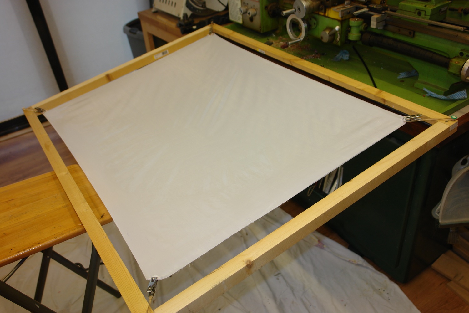
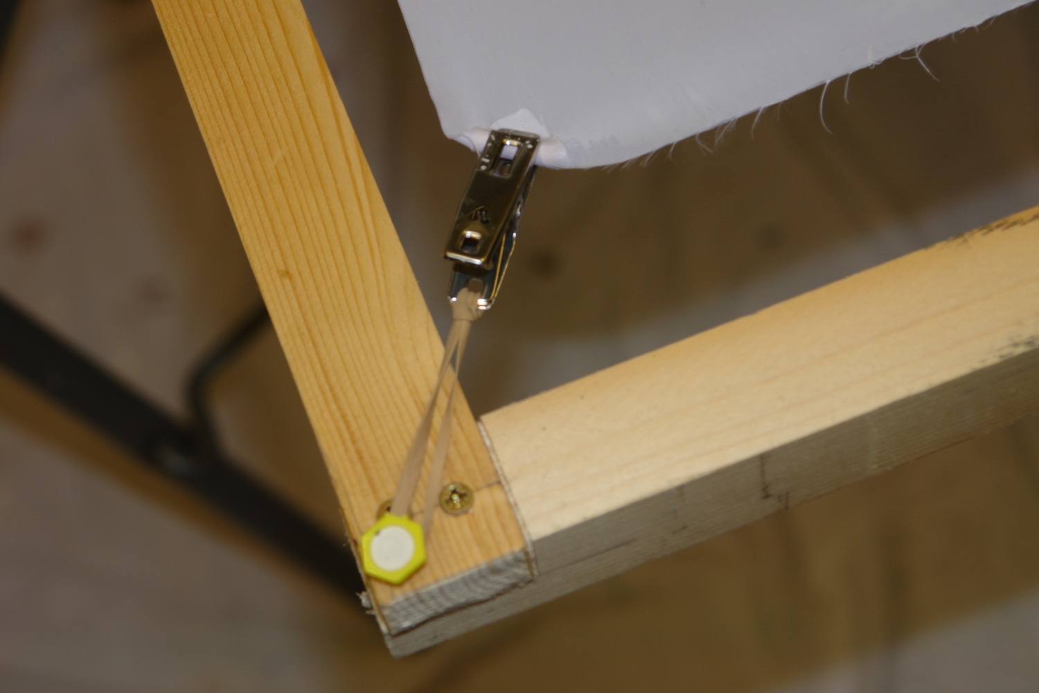
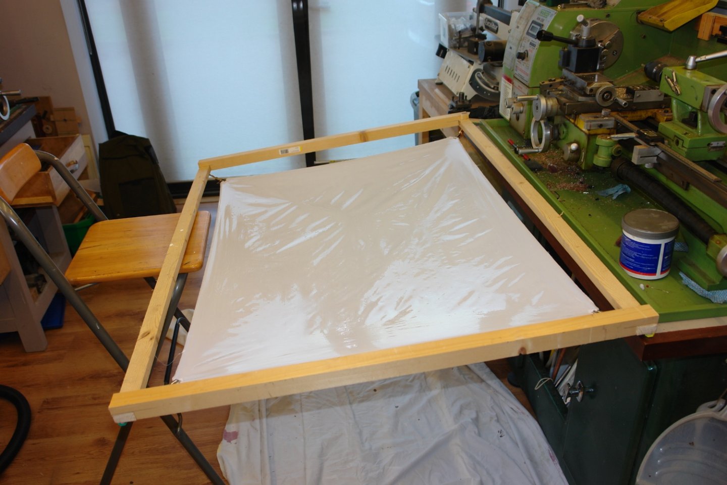
Thank you Keith, Steve, Andy and Brian, your comments are always welcome. Thanks to everyone for the likes. It got very hot here for a couple of days - 40.3 deg C a few miles up the road. The workshop faces north west so it never got higher than 25 deg. A good excuse for a couple of days of boat work. For a while I have been contemplating the sails. They are quite large requiring about 1.5 square meters of cloth. It would have been good to model them full of wind but at the size they are I don't think it will be practical to get the material to hold a curved shape. I am not planning to do all that sewing some of you are very good at. At 1/36 scale my quality of stitching would be much too heavy, so I will go with the "pencil" approach to detailing the seams. As for the material I got a sample of Silkspan (tissue) but rejected this as too flimsy. I also bought some low weight polyester (kite material) but didn't like the patten of the reinforcing threads so that was also rejected. I visited some of the local material shops to look at cotton but couldn't find anything I liked. In the end I defaulted back to what I have used before Amity sail cloth from Cornwall Model Boats. I think it is a polyester. The size of the Amity sheets is 1m x 0.7m so I had to buy two packs. I have a little left over from the previous model and hopefully this will make up for the slight shortfall relative to my estimated requirement. I also bought a couple of rolls of ripstop tape for reinforcing edges and adding the sail reinforcing details. I decided hot weather was the ideal time to get the sheets prepared. I started by building a frame just a bit larger than the maximum sheet size. I made it disassembleable learning from previous mistakes. I mounted the material on the frame stretched by elastic bands. I then gave it a couple of coats of 1/2 and 1/2 PVA diluted with water. Ideally the material wouldn't stretch but unfortunately it does. I tried to minimise the distortion but I would have liked to have done better. It will be interesting to see how it turns out. The 2 sheets are done and dry courtesy of our record breaking weather. It's an ill wind that blows nobody any good!!!!


-
Eberhard. Beautiful job - to my eye much more realistic than the previous one. Practice makes perfect.
-
Nils - thank you - very useful. Pity about the cloth, i always find it difficult to get the right stuff.
- 180 replies
-
- 2
-
-
- pilot boat
- Elbe 5
- (and 3 more)
-
Thanks for sharing. its always goods to see something unusual.
- 31 replies
-
- 2
-
-
- Sailing Canoe
- Finished
- (and 1 more)
-
You seem to be cracking on at quite a pace Jon. i agree the deck accommodation does seems to be on the ample side.
-
Almost over before it started, looks lovely.
-
A little gem Javier.
-
Cap San Diego by mikegr - 1/160
KeithAug replied to mikegr's topic in - Build logs for subjects built 1901 - Present Day
Coming along nicely. -
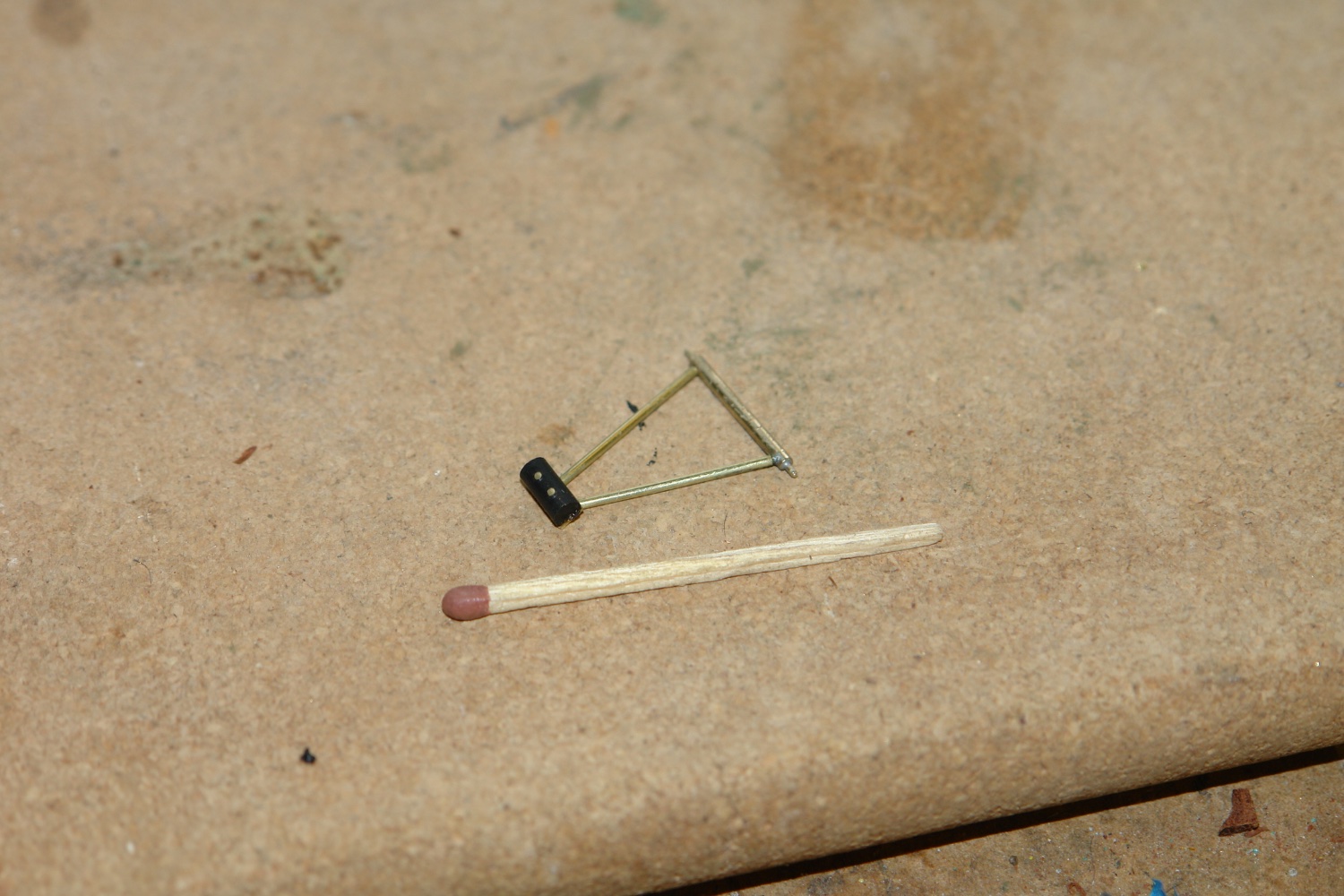
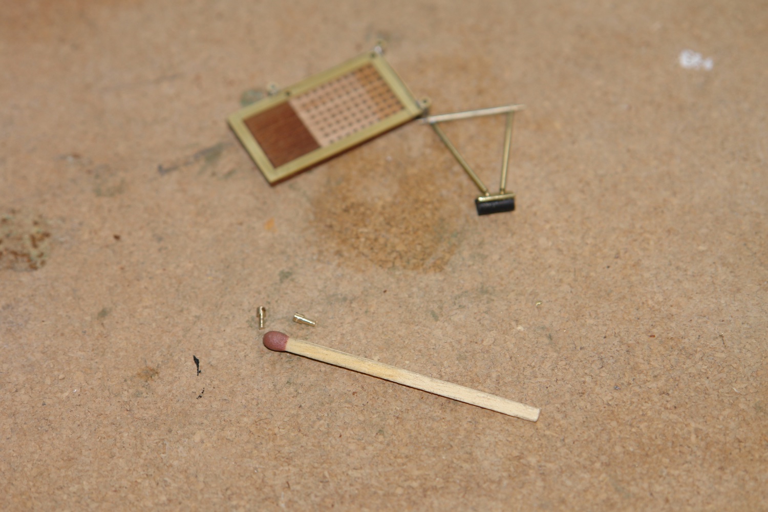
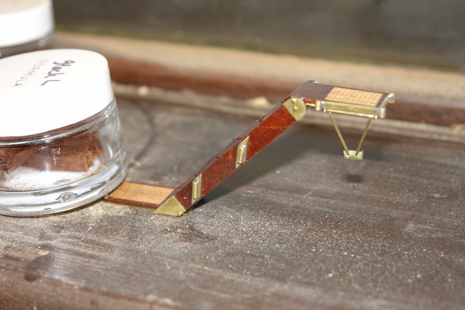
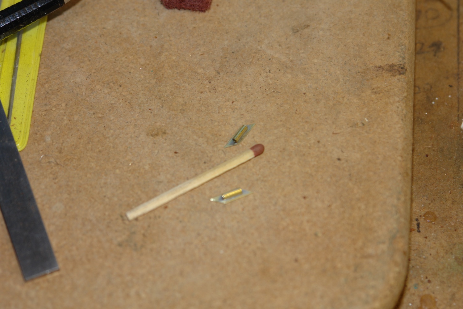
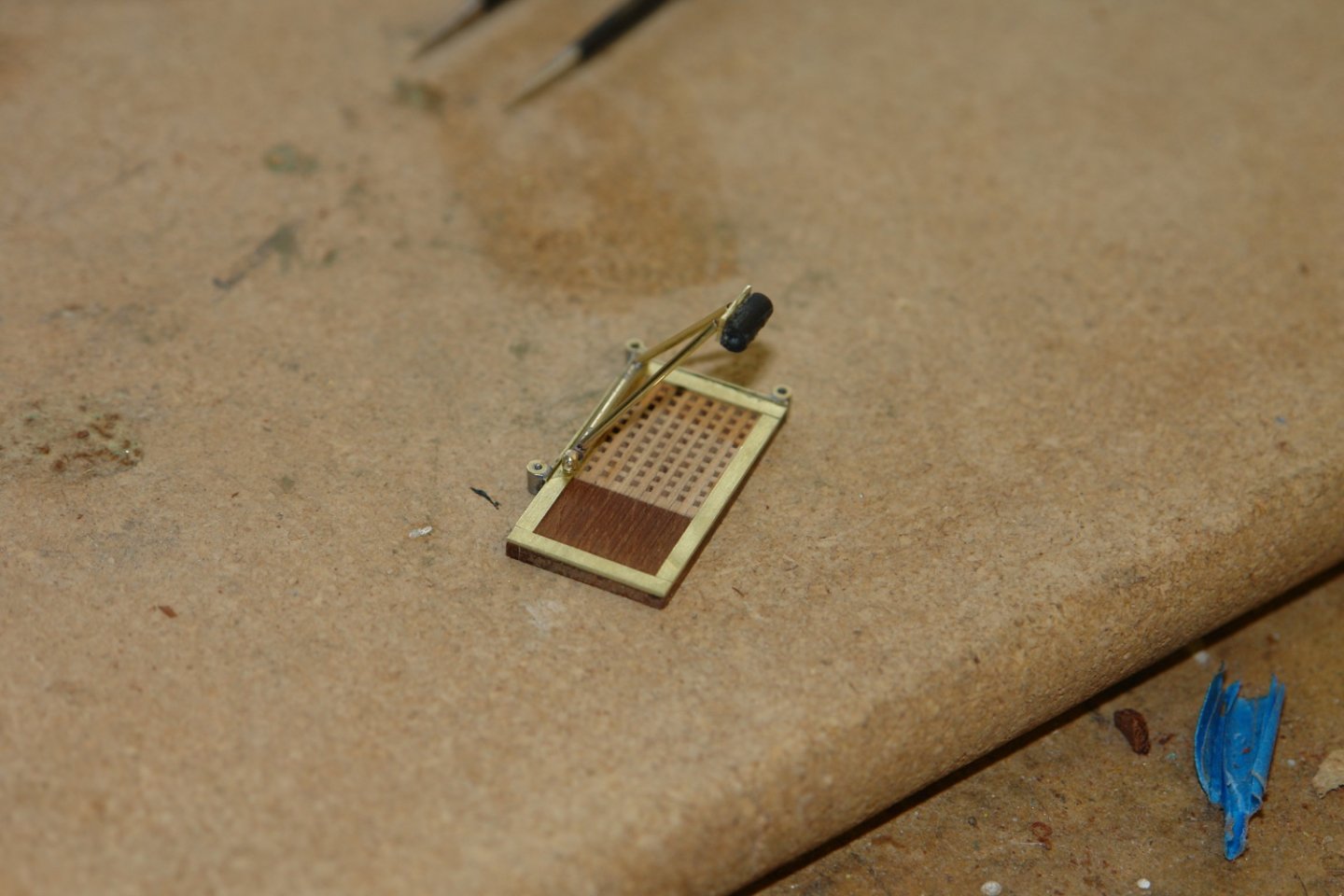
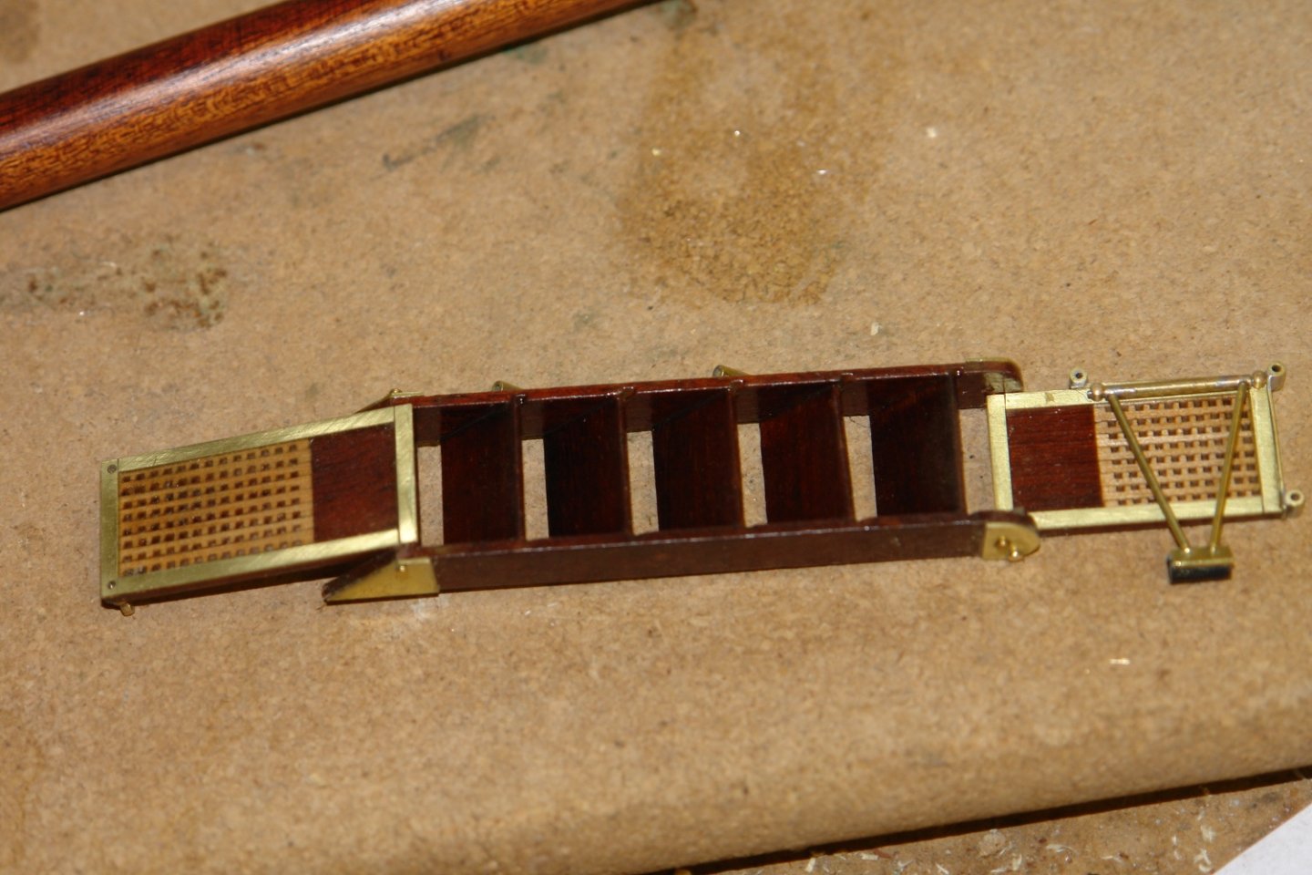
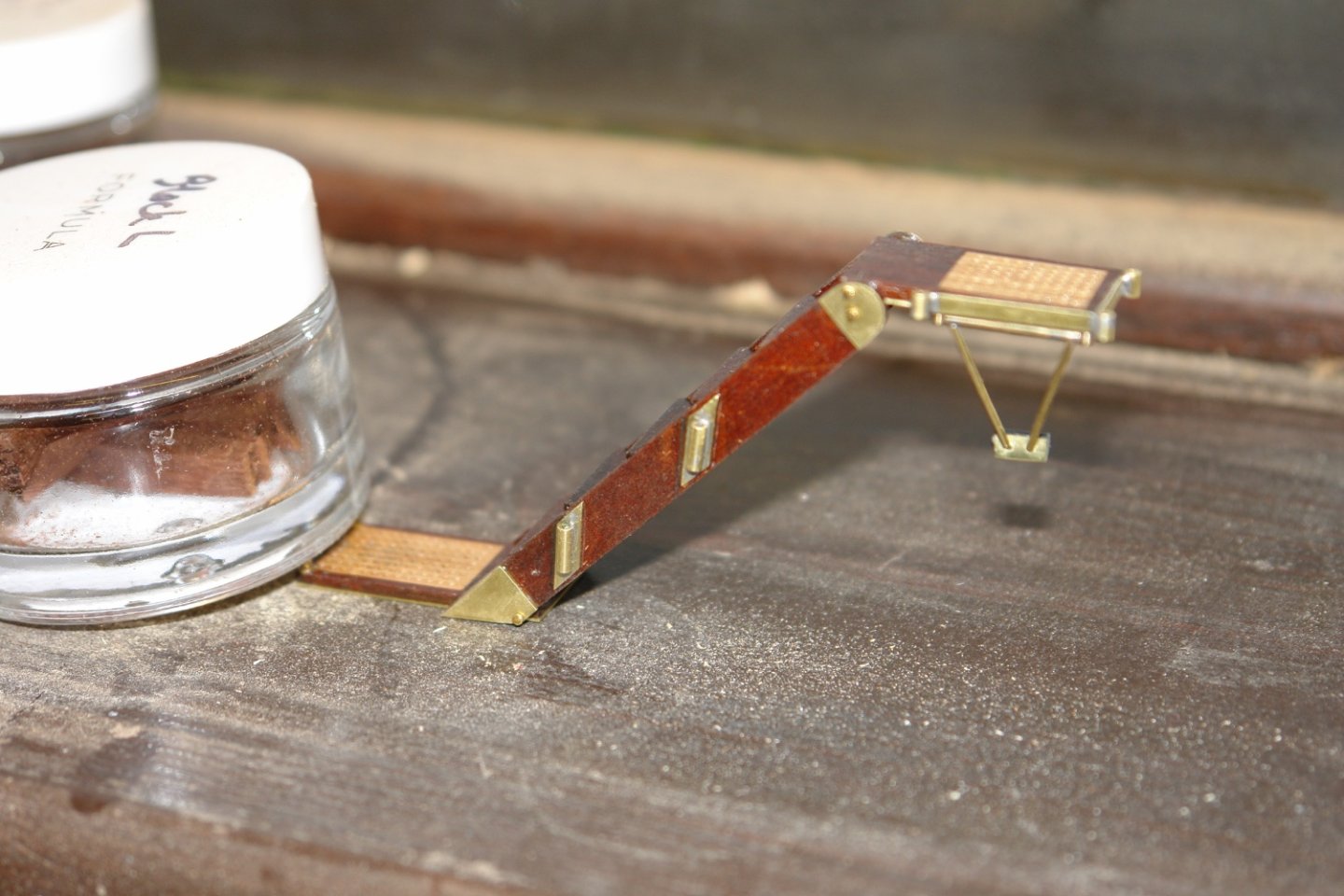
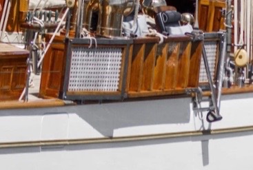
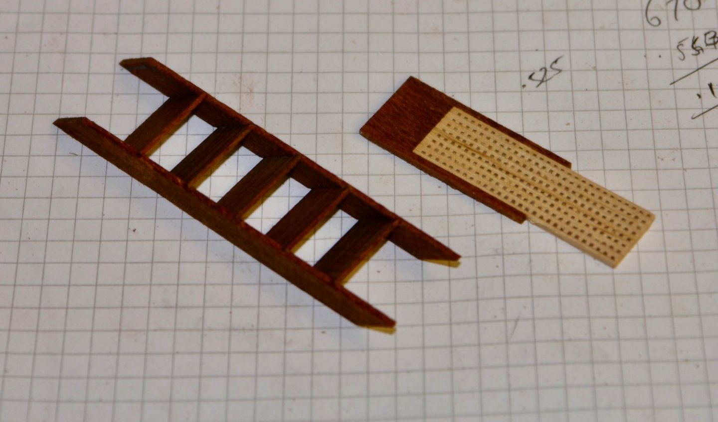
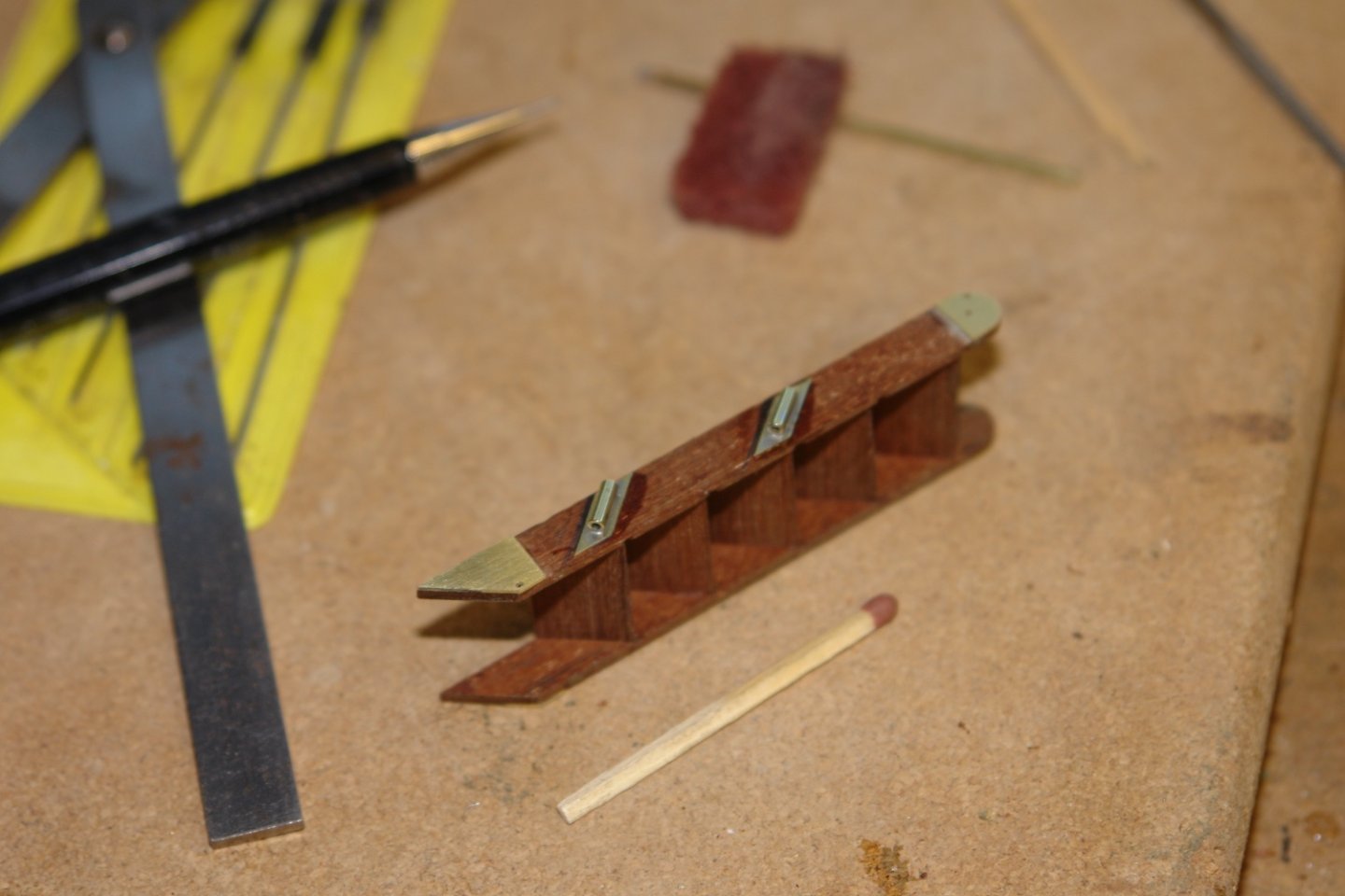
Nils, CPDDET, John, Steve and Pat, thank you for commenting. Its been pretty warm here - touching 33c Monday and due to get hotter. Not warm by what many of you see but certainly unpleasant enough here. I finished the steps by making the support piece. It is a triangular frame pivoted at the wide end with a rubber buffer on the pointy bit. It swings into place on 2 hinge pins (next two the match head) These pins mount on to the frame on to the underside of the top platform. The upper and lower platforms were attached to the steps by pivot pins. Here the steps are photographed in the working position. The steps are folded flat for stowage on the rail.


-
Eberhard, sorry to hear your covid news. It is starting to feel like my wife and I will be the last ones standing. No doubt our turn will come soon. The planking looks excellent, very impressive.
-
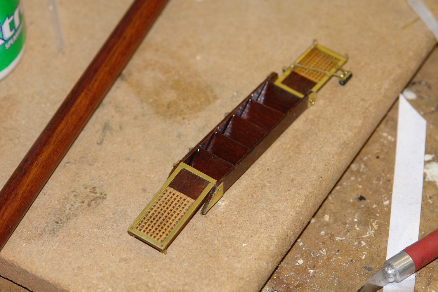
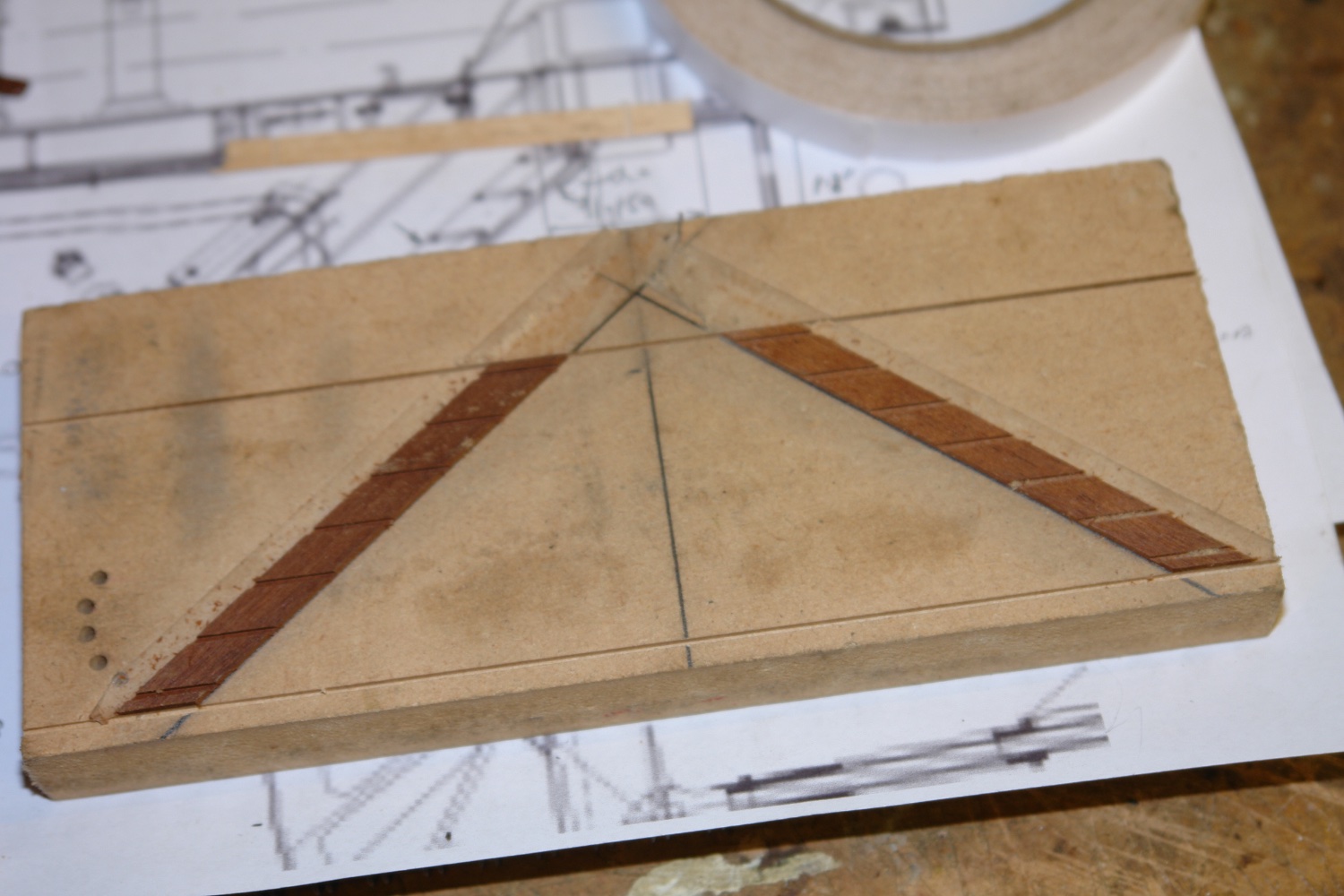
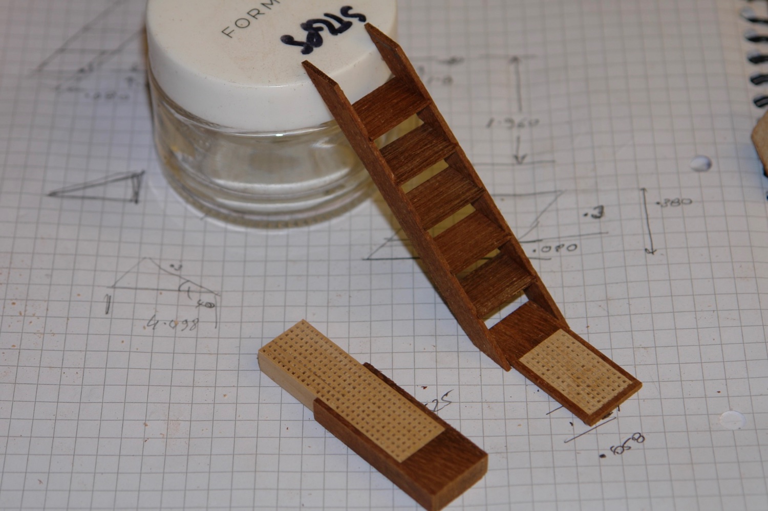
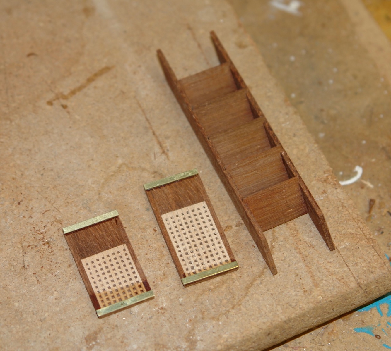
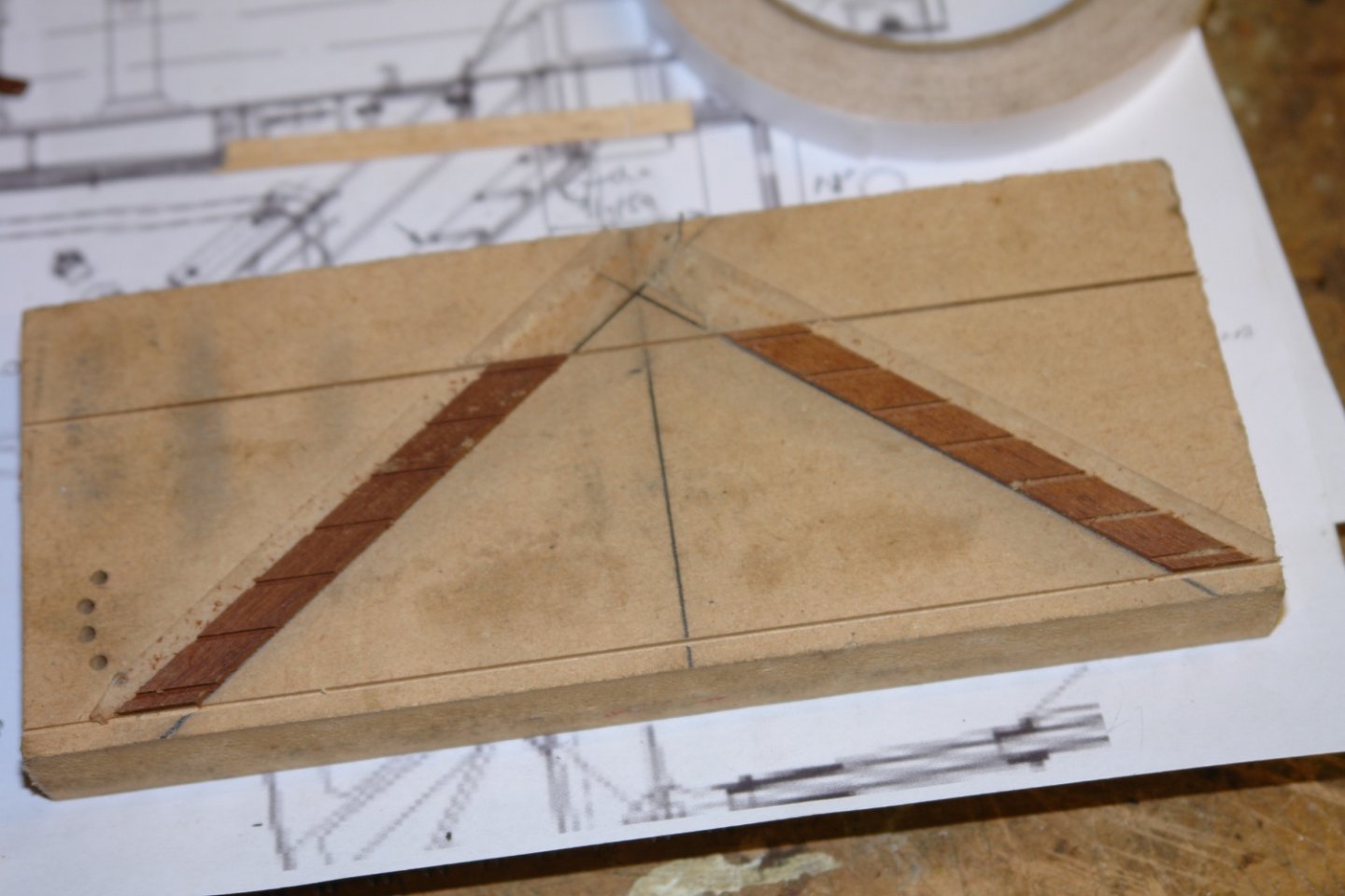
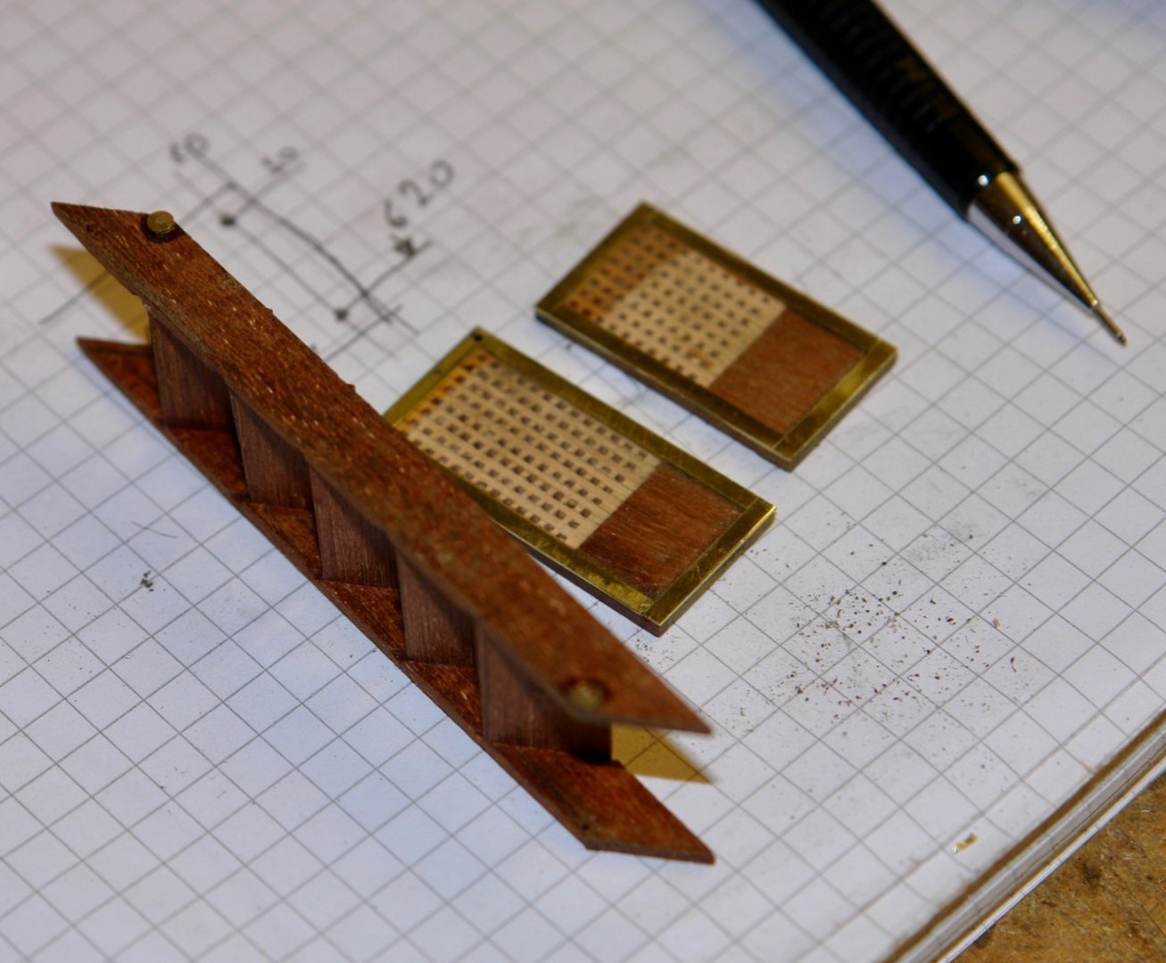
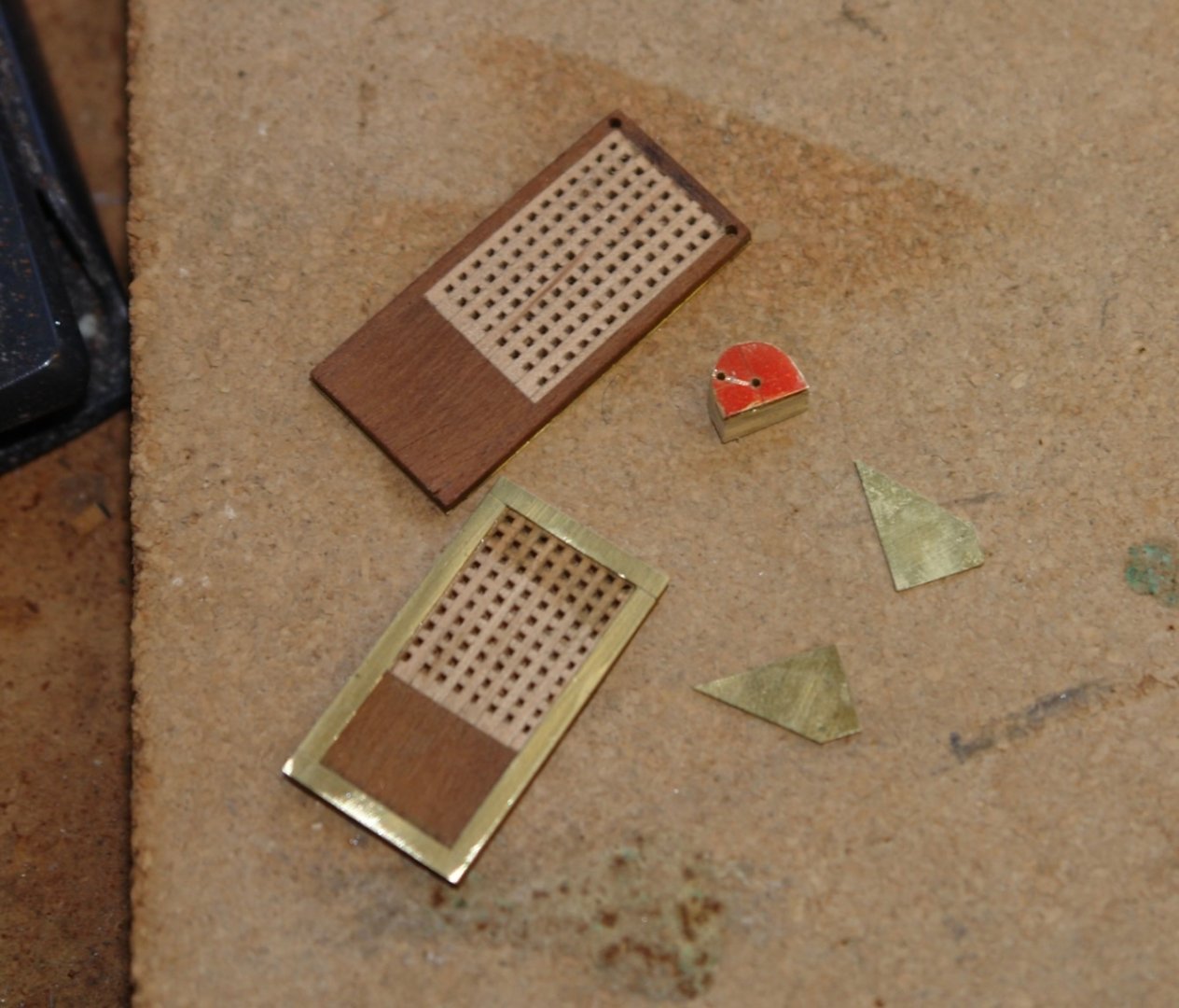
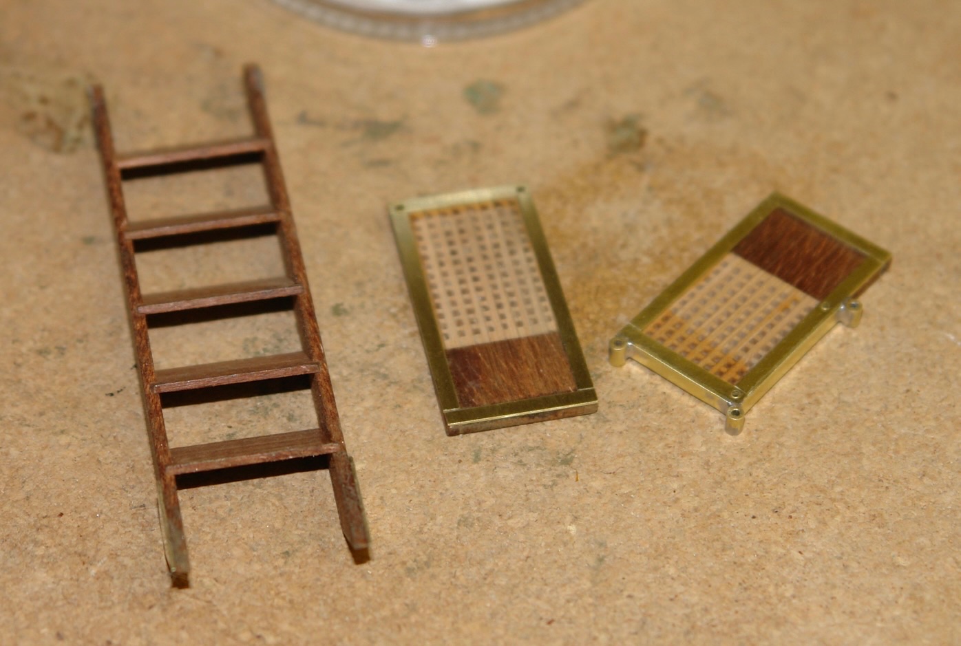
Pat, Mark, Keith, Greg, Brian, Andy - thank you all for your kind comments. The weather has been good here for a couple of weeks which means most of my time has been spent in the garden. I did find a bit of time for the boat and concentrated on the boarding steps. These fold up to store on the starboard rail. I started by marking out the angle of the steps on a sheet of MDF before attaching mahogany strips to this with double sided tape. The strips were then slotted to half their depth using the table saw. The slots were .040" wide by .030" deep. The strips were then removed and 1mm thick steps were cut. The sides and steps were then glued together. The bottom and top steps are extended to form a platform and both are hinged to fold flat. These upper and lower steps include a grating section and fortunately I had grating material available from earlier in the build. The upper and lower steps are heavily braced with metal strips. The step sides are also reinforced at the ends with metal plates. These reinforce the pivot points. The top platform has mounting holes for the demountable stanchions. These were made from tube and soldered in place. One side of the steps has mounting brackets for more demountable stanchions. I now need to make the support frame that braces the upper platform agains the hull.


-
Well that was an extensive and excellent update Brian. Why did you decide not to use brass for the ships bell - not withstanding the question the bell looks excellent.
-
Nils - I bought a Canon TS8050 several years ago and found it to be quite temperamental, possibly due to my incompetence. I hope you have more success. Good start on the sails - as you say the printing looks excellent.
- 180 replies
-
- 2
-
-
- pilot boat
- Elbe 5
- (and 3 more)