KeithAug
-
Posts
3,980 -
Joined
-
Last visited
Content Type
Profiles
Forums
Gallery
Events
Everything posted by KeithAug
-
Not long ago I shipped a pair of collet chucks (1kg) from the Uk to Australia using the Royal Mail. The shipment went via air mail and cost £19 which I thought was pretty decent, it didn’t take long either. Everything was above board with all the correct customs declarations etc. It seems to me that some shipping costs are reasonable while others seem exorbitant. If I judge the total cost (price plus shipping) to be unreasonable I just don’t buy. In the instance of the 2 collects I actually bought them in the Uk for another msw member and he paid me for them and for the shipping via PayPal. This may be an option for some of you struggling with unreasonable shipping costs.
-
 Hi Keith, I am using Beadalon wire and the spec says the wire is nylon coated. I cut 3 different diameters of beading wire and placed them in sealed container of 99.8% acetone and left overnight. In the morning the nylon was pristine, showing no degradation. I then looked up the compatibility of nylon with acetone and found the compatibility to be “excellent” ( I.e acetone does not dissolve nylon ). Acetone does however dissolve a range of plastics. As an aside the acetone I have was bought in a plastic bottle - so clearly some plastics are acetone resistant. When you commented “It works” I am guessing you did a bit of experimenting? Dan, Tom, Keith, Hakan, thank you for your continuing interest and comments.
 -
Dan - thank you for the comments - I think I have sorted out the link but let me know if it doesn't work.
-
HMCSS Victoria 1855 by BANYAN - 1:72
KeithAug replied to BANYAN's topic in - Build logs for subjects built 1851 - 1900
Very impressive rope planning Pat. Is your rope walk a home design or a commercial unit?- 1,013 replies
-
- 2
-

-
- gun dispatch vessel
- victoria
- (and 2 more)
-
Stunning Rob, Im sure your museum colleagues will be in raptures.
- 3,560 replies
-
- 1
-
-
- clipper
- hull model
- (and 2 more)
-
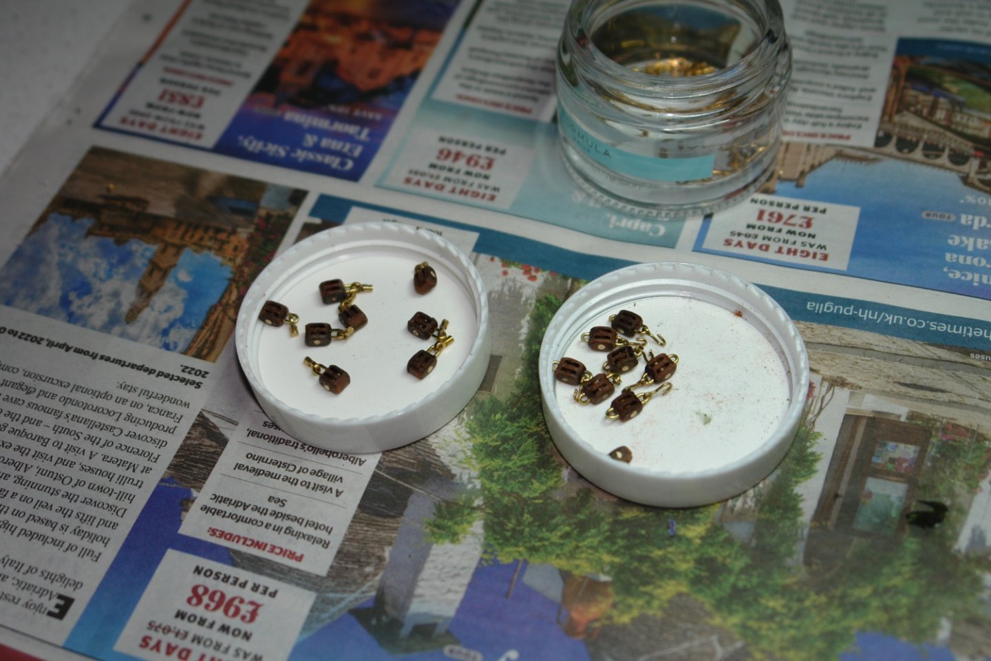
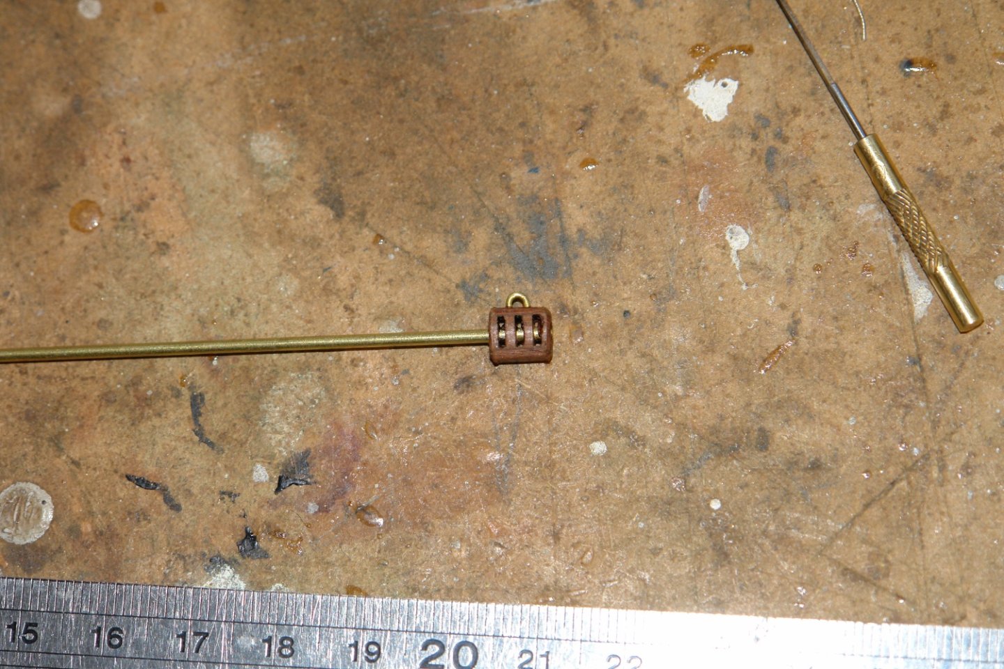
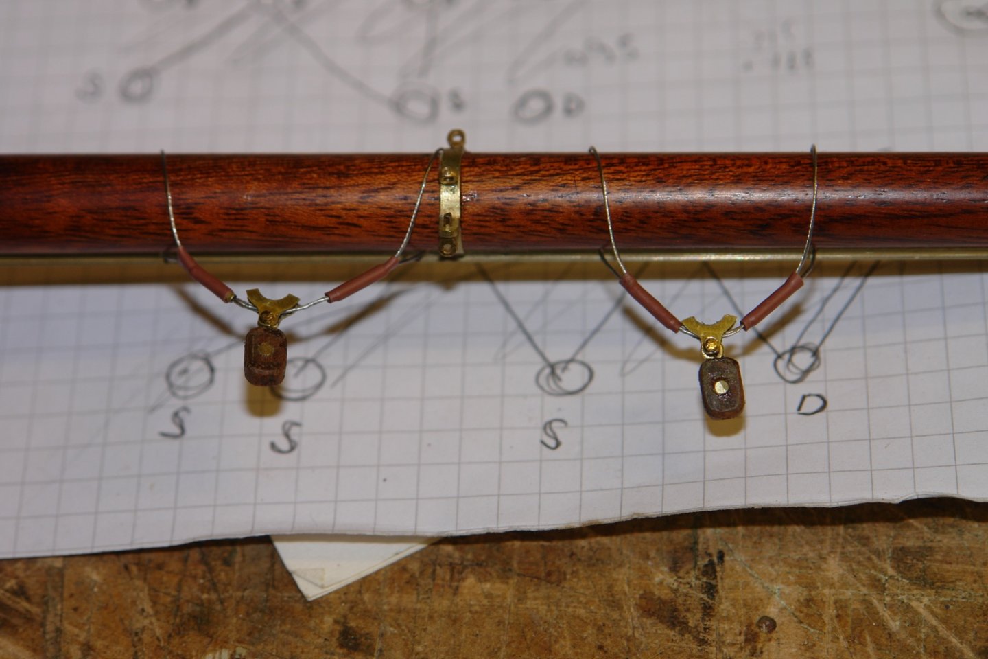
I did a bit more work over the last couple of days. I finished off a number of medium sized single, double and triple blocks. The 3 sizes I have rationalised on are 5mm, 6mm and 7mm high. Depending on the use / location of the blocks they have various attachment fittings. I also needed to make more of the strop brackets for the main and foremast gaff bridles (5 in total). This time however I was a bit more economical making 3 parts from each fabricated ring. I then moved on from the main boom to work on the main and fore gaffs. Two single blocks were attached to the main gaff saddle. These will take the main boom topping lifts (one on each side of the mainsail). Then a double block was attached to the gaff to take the gaff hoist halyard. I then attached the 3 bridles to the main gaff. (I did this before yesterdays debate on simulating the leather protecting sheath). Depending on the outcome of experiments I may have to revisit this. Two blocks are attached to the end of the gaff to take the sheets for the topsail. I also attached the twin bridles to the fore mast gaff. I then attached the blocks for the for topsail sheets as per the main gaff.


-
Cap San Diego by mikegr - 1/160
KeithAug replied to mikegr's topic in - Build logs for subjects built 1901 - Present Day
That is what I have used it for. Strips of about 1/2 inch wide twist very easily.. -
Mark - it burns off quite nicely. You set fire to one end and then it burns almost like a fuse. It does create a molten blob so the trick is to blow out the flame and then quickly draw the wire between the thumb and fore finger to remove the blob. Then you utter an expletive and remember next time to wear your gloves. The problem is the burning discolours the wire strands in a way that isn't easily rectified. Really you need the wire to retain its shiny stainless steel look.
-
Cap San Diego by mikegr - 1/160
KeithAug replied to mikegr's topic in - Build logs for subjects built 1901 - Present Day
If I am understanding correctly why not use 1/32" birch ply, glued in place with PVA glue. I have used this in the past for bulwark strengthening webs and it worked fine. I would steer away from balsa as it isn't very durable. Sorry if I have misunderstood. -
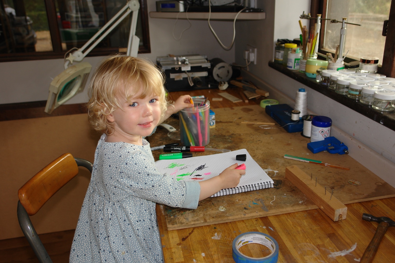
Well remembered Keith, indeed it is, although she hasn't been called Splodge for a while now. At nursery school they all use her given name of Eve but in the family she answers to Bean. I think "Bean" will stick with her forever. Her mum brought her to the workshop to show her Germania. I pointed out the picture of Maisie (the Dalmatian) in the porthole and I removed the deck house to show her the picture of Bean. She then rushed back to the lounge and reappeared with Nanny to show her the pictures. It was after this that she decided to stay and do her work. Steve I will do a test piece. My guess is that acrylics will flake and enamels will form beads. The wire is covered with clear plastic (which looks and feels a bit like nylon) and i am dubious about the adhesion. Pat - Yes you can get small bore heat shrink. The wire is .020" diameter and the problem is that small bore heat shrink seems to have a reasonable wall thickness. It more than doubles the diameter of the strops and this makes them look unnaturally heavy. Thank you Eberhard for the apron explanation. Thank you all for the nice Bean comments - unfortunately she is not for sale.
-
Wonderful Brian, I hadn’t thought of sanding practice. I obviously missed the “training productivity” aspect of her visit, thanks to all of you for pointing it out.
-
So what is next Rob?
-
HMCSS Victoria 1855 by BANYAN - 1:72
KeithAug replied to BANYAN's topic in - Build logs for subjects built 1851 - 1900
Nice work Pat. That turned out well.- 1,013 replies
-
- 2
-
-
- gun dispatch vessel
- victoria
- (and 2 more)
-
I have always found these French ships to be a bit of a designer dogs breakfast. While not a fan of the aesthetics I do find them really fascinating. Hence I am enjoying your excellent build. I see the big advantage of the printer approach -------- you are allowed to make it on the lounge carpet. My dusty wood approach would never make it to the lounge during construction.
- 132 replies
-
- 3
-
-
- charles martel
- battleship
- (and 1 more)
-
Today I had a big productive workshop plan. Then this arrived and insisted on helping. She said that she needed to do her work so we did a bit of nailing practice (see hammer and wood block). Then we learned masking taping before progressing on to drawing boats. I have high hopes that she is destined to become a ship modeller. Needless to say I didn't get much done.

-
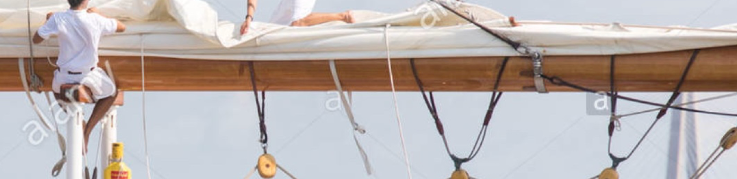
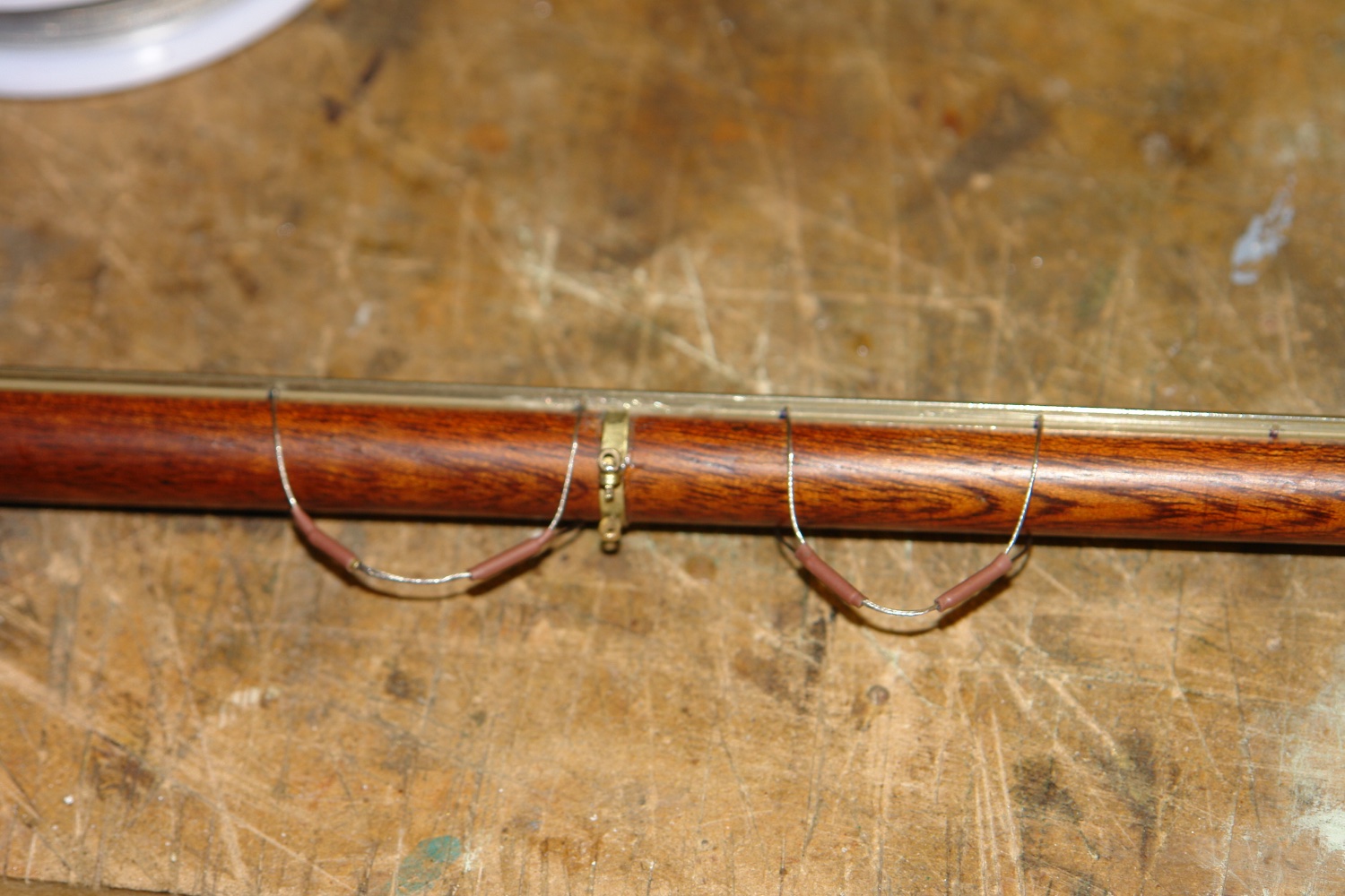
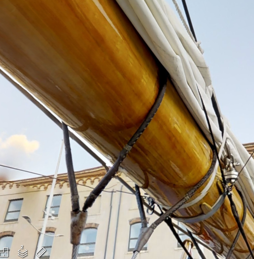
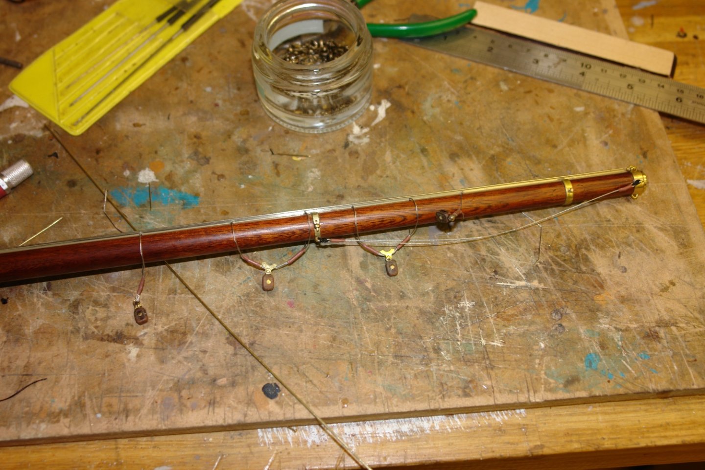
Here is a better photo. Given the strops start level with the transome I think the foot rope idea makes the most sense. Unfortunately they were not great at safety. One young crew member fell to her death while working aloft in March 2017.

-
Brian - Eberhard is probably the expert. Watchmakers have a cloth on the bench that attaches to a chord around their neck. I just trust to luck and make a few spares. Thank you for your kind remarks.
-
Hello Steve They have a very closely fitted leather covering. It is a bit too closely fitted for me to reproduce neatly. Eberhard / Steve. I think the foot rope idea seems sensible. Given the mass and height of the boom I think that flicking it across would be better managed via the sheets and winches. Gary, Druxey, John, Pat, Eberhard and Steve - thank you all once more for your supportive comments
-
Nice lot of small parts Roger. How many spares have you made to feed the workshop black hole?
-
Lovely little boat. Well done.
-
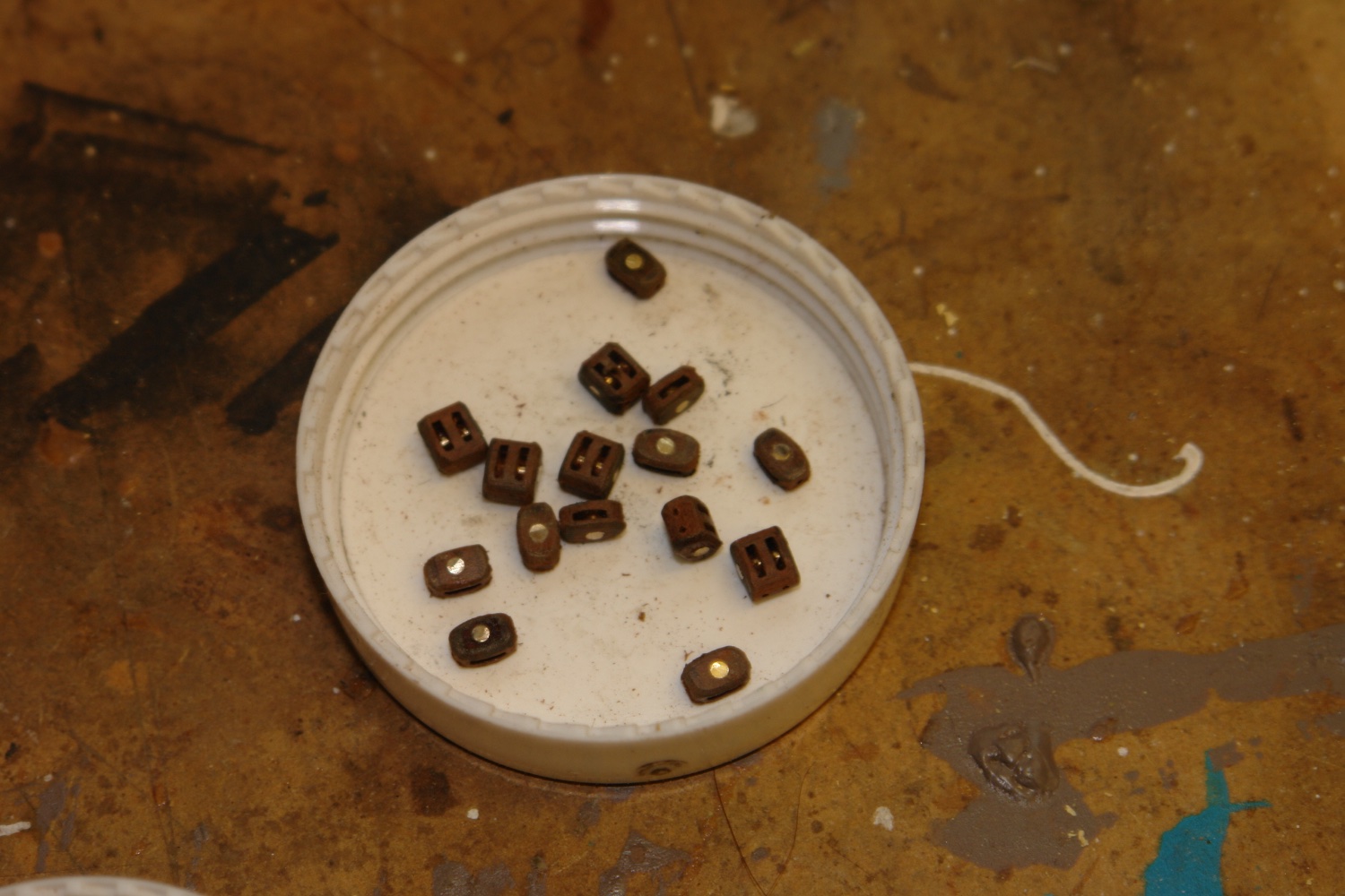
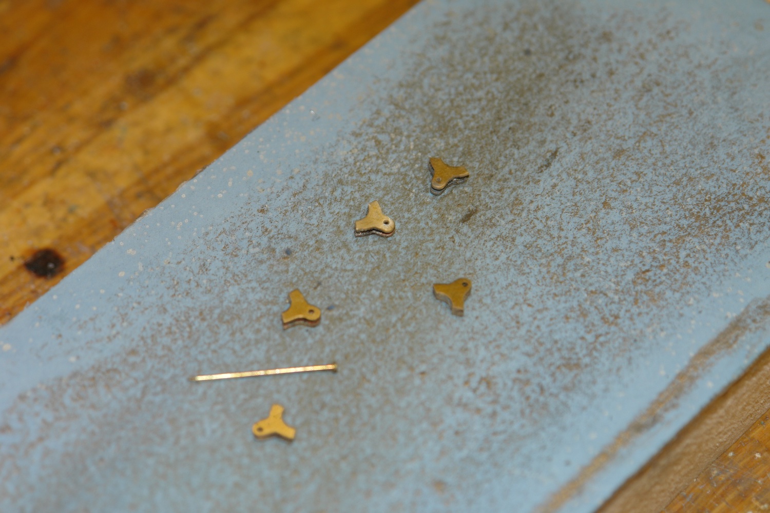
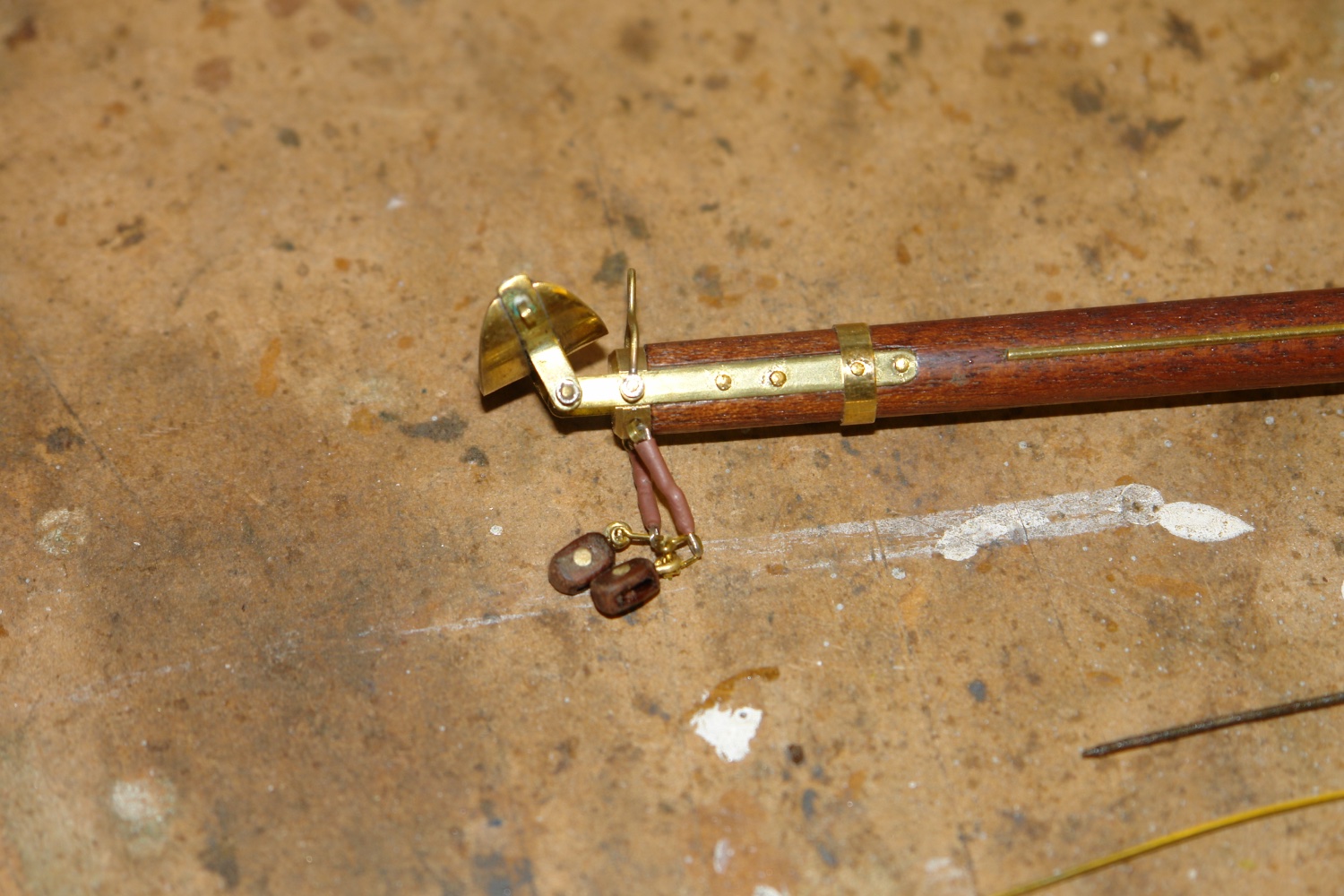
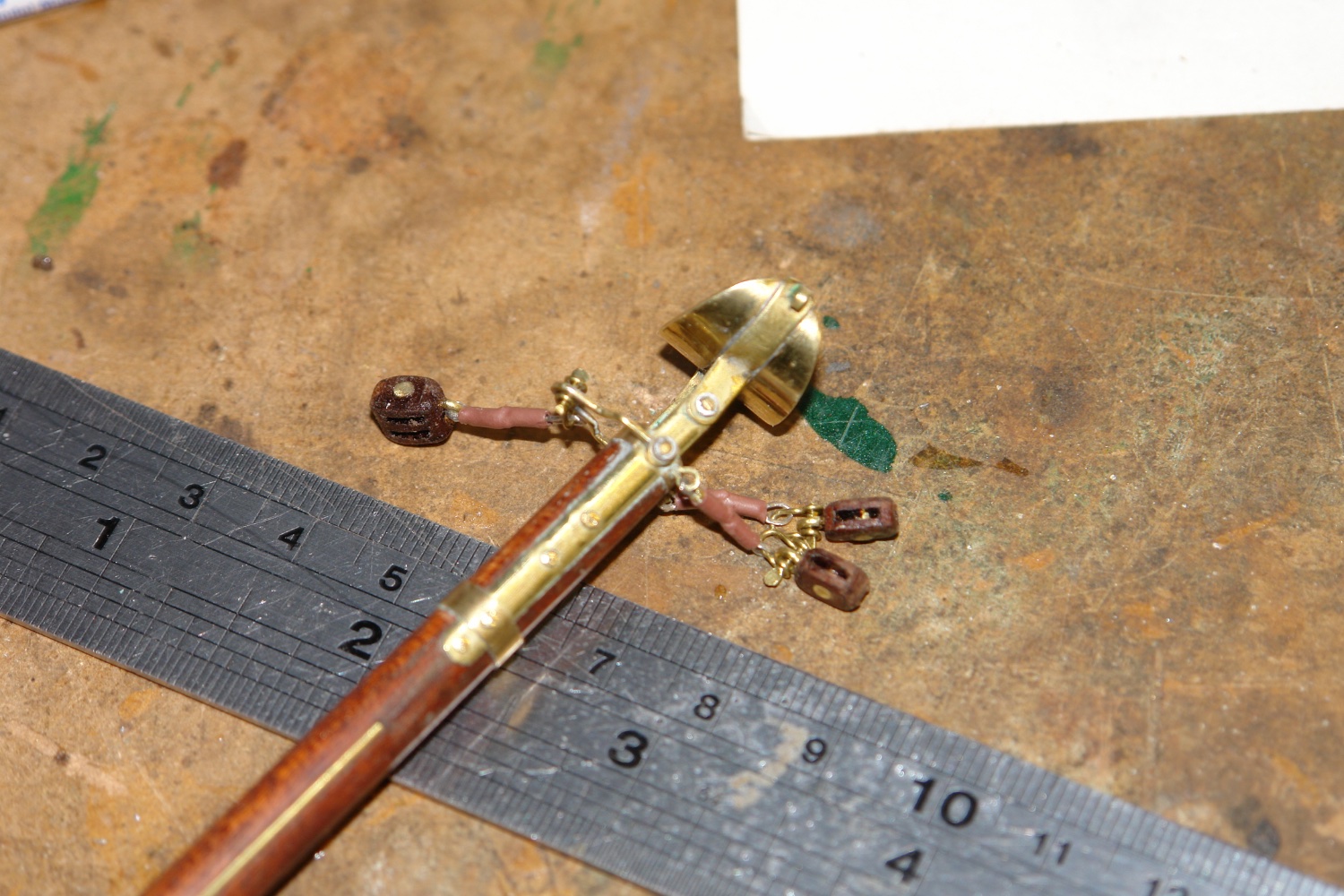
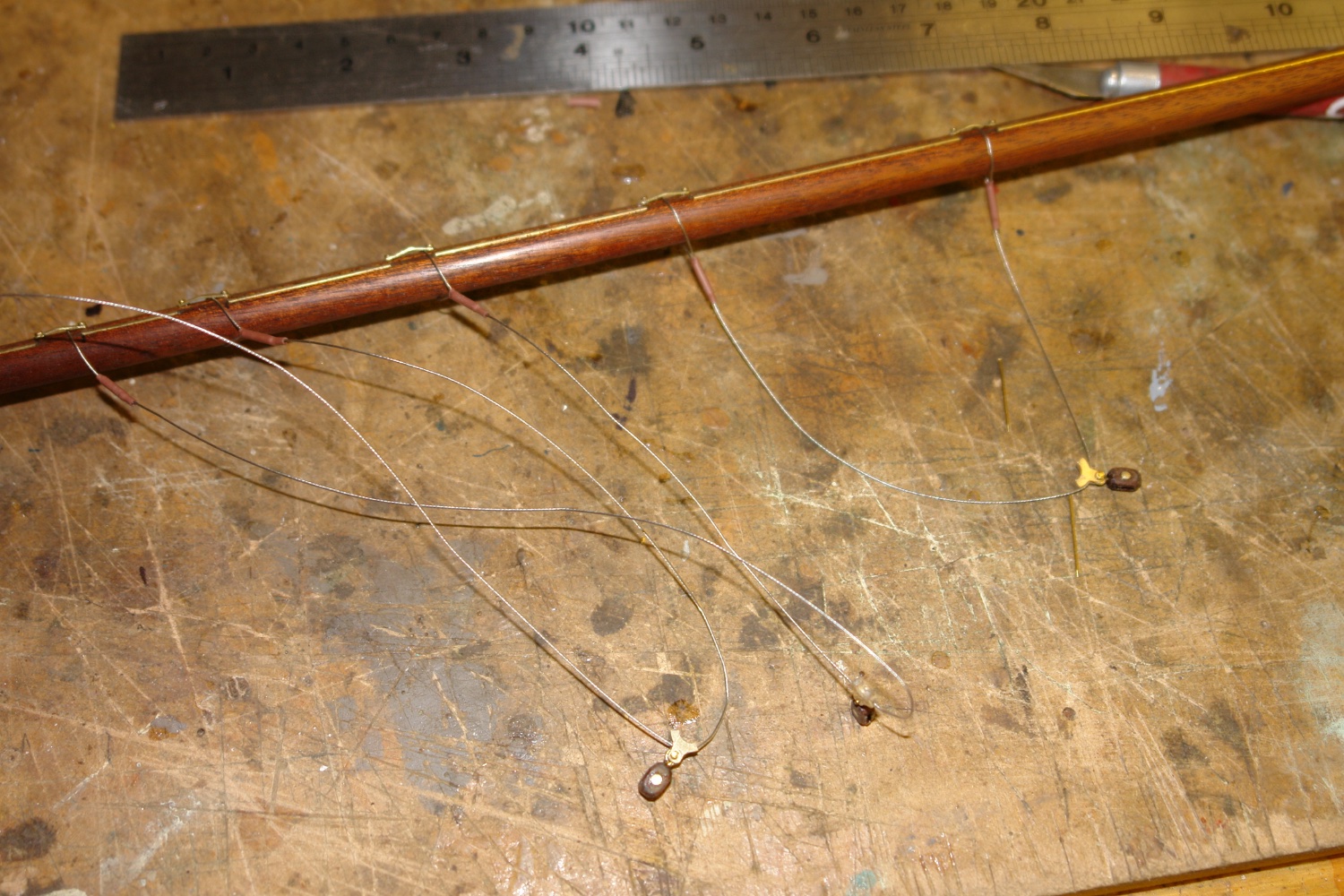
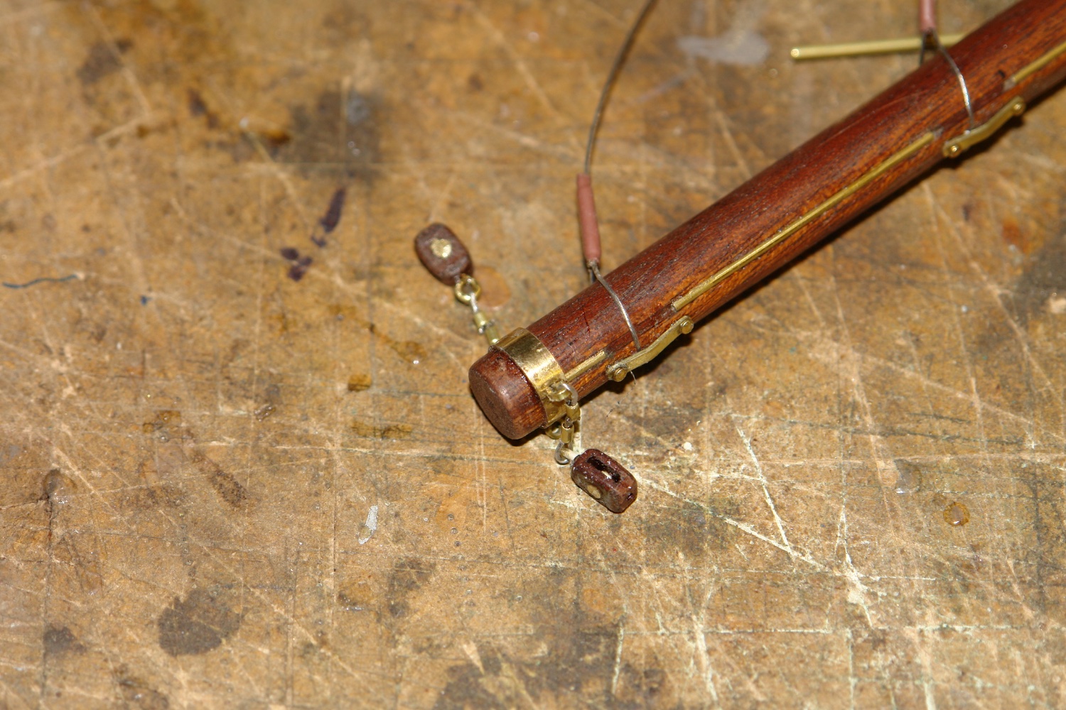
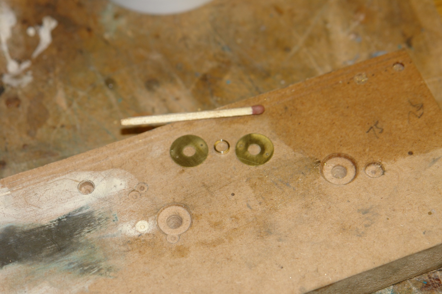
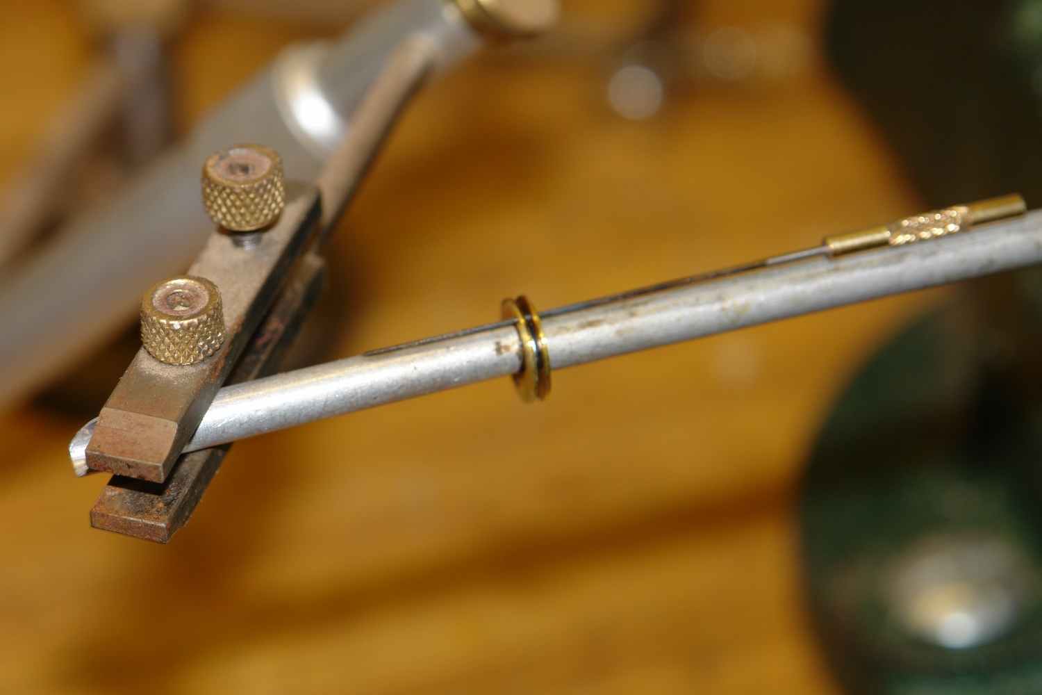
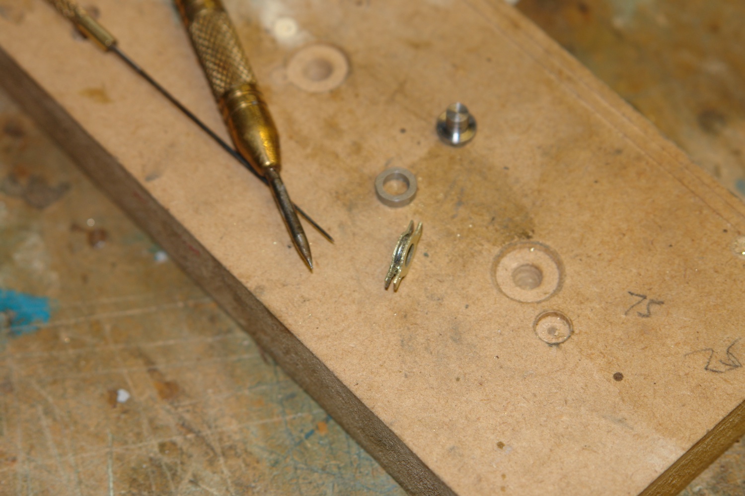
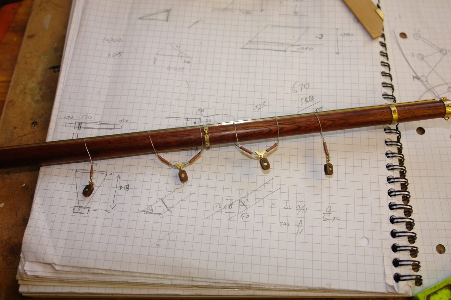
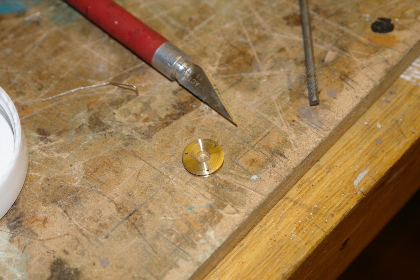
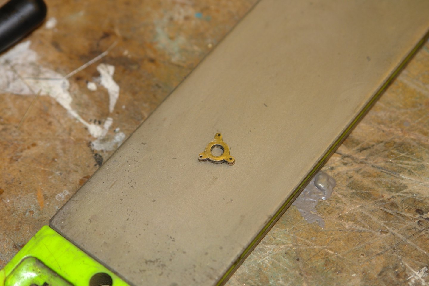
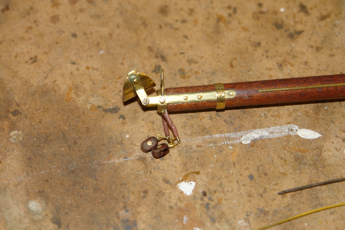
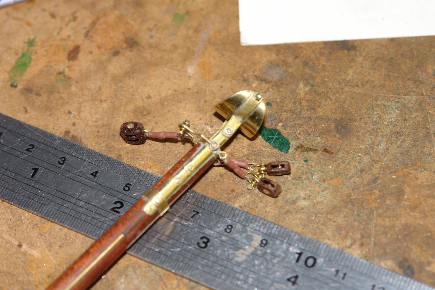
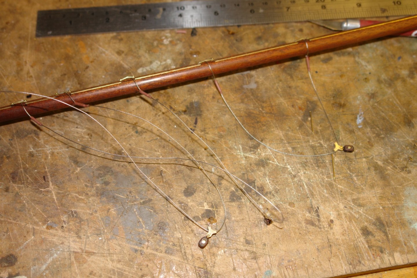
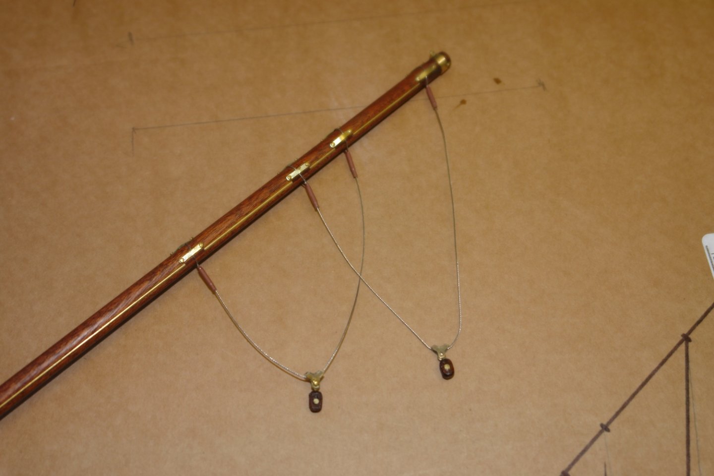
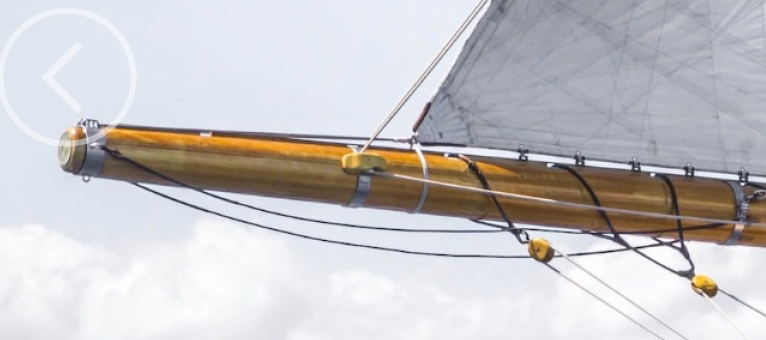
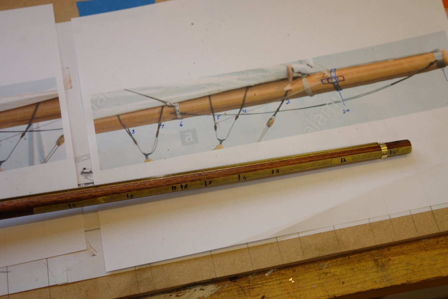
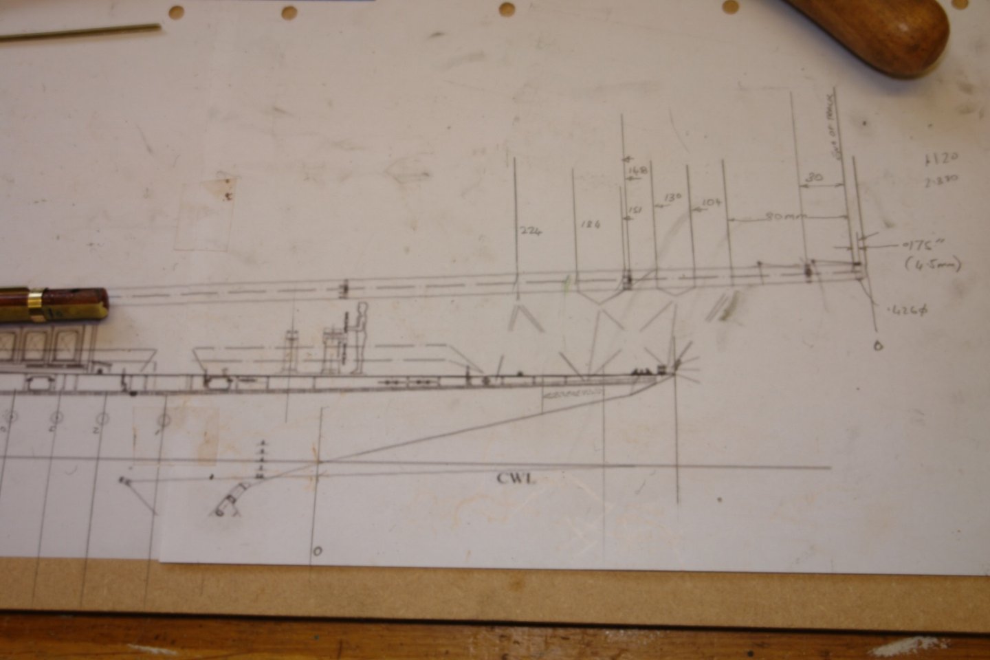
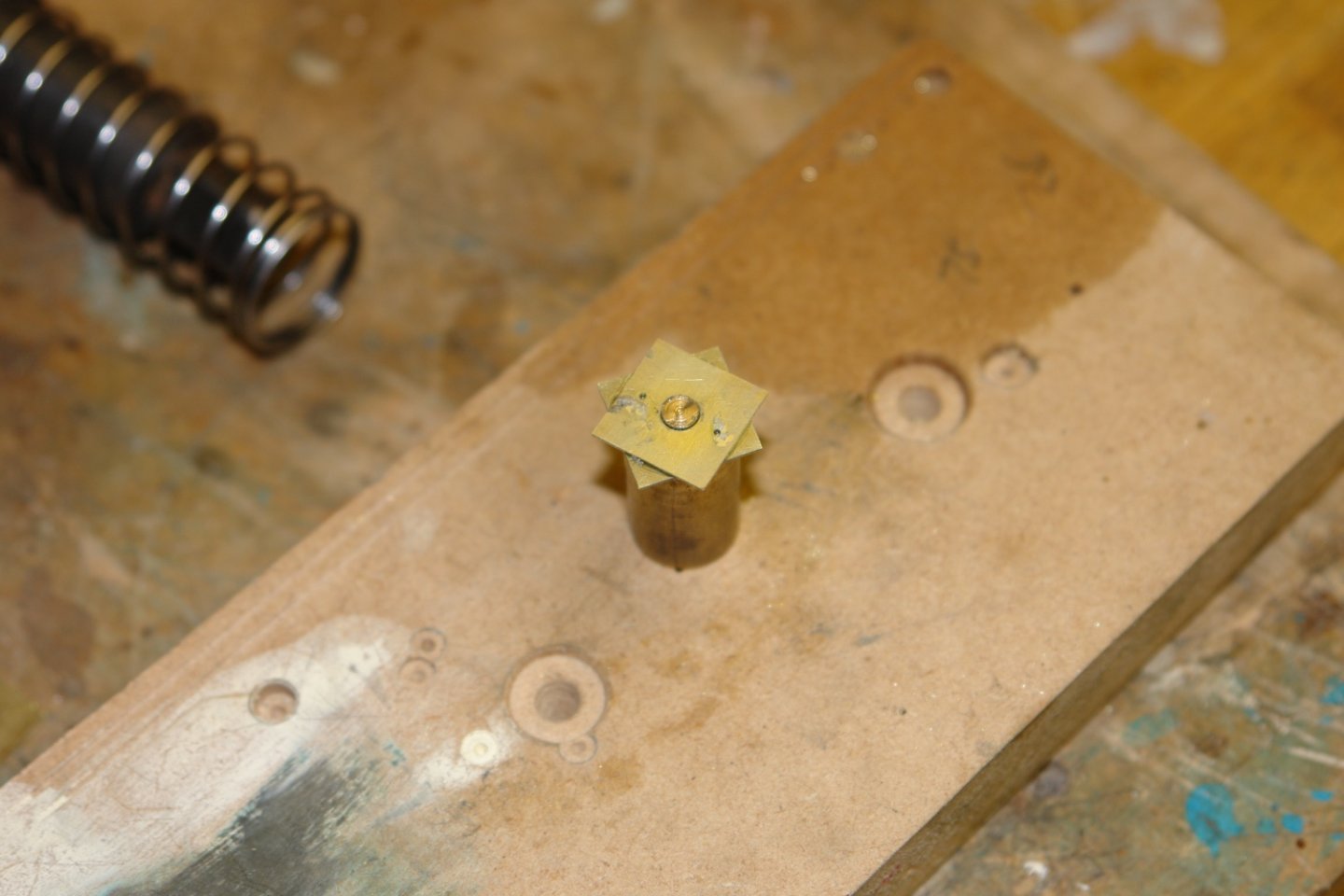
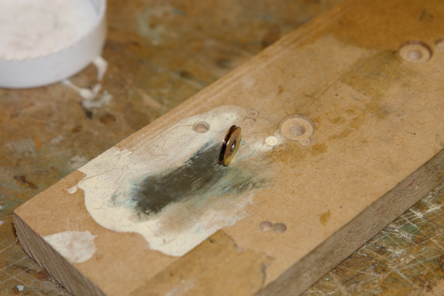
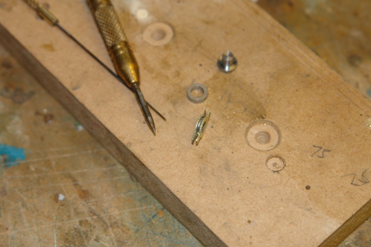
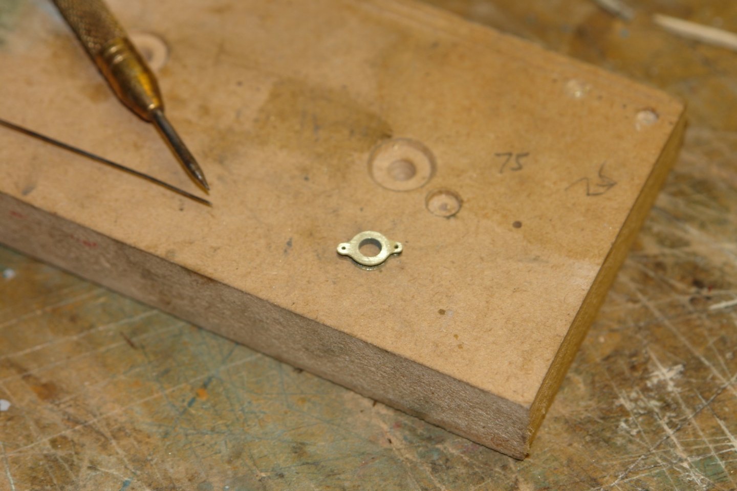
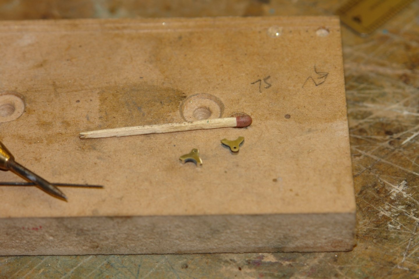
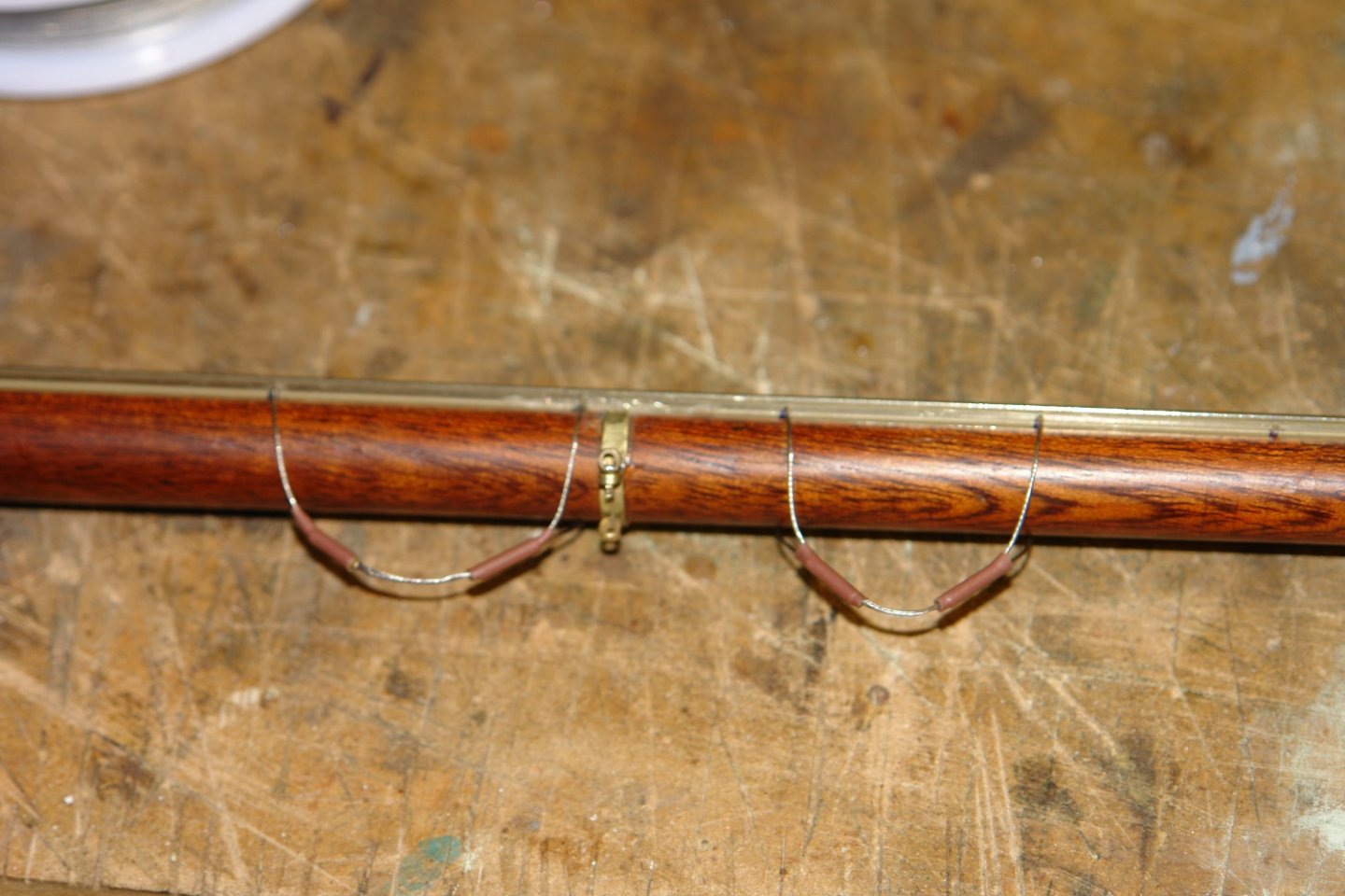
Thank you all for your comments and likes. I am moving on by going back to the masts, booms and spars which were only partially completed earlier. They have all sorts of fitting and attachments which need to be made and installed before I get on to the sails. I am starting with the main boom. You can see in the following photographs the blocks and strops. Do health and safety at work regulations apply to yachts? The rudimentary plans downloaded from the internet adequately define the attachment points These were marked on to the boom (on top of a piece of masking tape. The blocks attach to the strops via brackets. These were probably forged from plate on the original. They are a bit small at model scale and so I decided to fabricate them. I started with 2 squares of brass sheet drilled with a central hole and 2 other smaller holes. The squares were turned circular. and a spacer was made. The 3 parts were assembles and soldered on an aluminium alignment mandrel. I then made a filing button and used this to profile the outer shape. Two brackets were then cut from the profiled shape. The wire strops were then made from beading wire. I spent a lot of time making blocks in 3 sizes and with single double and triple sheaves. Single blocks were attached to the strops via the brackets. Two further single blocks were attached. I am not sure what the purpose is of the long strops running fore and aft are, but these were added. Much more to do.


-
Eberhard, I can remember what it looked like and I am pretty sure that it wasn't made by Rolls Royce. I don't remember the make but I did try t look up the training centre on the web to see if i could find out what happened to it. Unfortunately I drew a blank. I do intend trying again.