KeithAug
-
Posts
3,980 -
Joined
-
Last visited
Content Type
Profiles
Forums
Gallery
Events
Everything posted by KeithAug
-
 Eberhard - A good plan but not fool proof. We once had so find the yacht after a thick mist descended but drink made us brave and we were lucky. I too remember all those beach bars and lethal cocktails, even more lethal the day after I recall.
 -
Yes many times - usually on route to pub when the motivation was high and then back from the pub when senses were dulled. But i was much younger then!
-
Byrnes Saw Mini Sled
KeithAug replied to Roger Pellett's topic in Modeling tools and Workshop Equipment
Does the prize outweigh the downside of being dead? -
Byrnes Saw Mini Sled
KeithAug replied to Roger Pellett's topic in Modeling tools and Workshop Equipment
Roger The thief's among us would like to see a photo showing the rear side of the angle please. I am wondering how far you went with the saw slot. Also did you consider making the slot as wide as your thickest blade, it looks on the photos as though it is the size of the installed slitting saw? The stop modification will also be of interest. I have a spare 1/2" micrometer body and was considering how this might be incorporated. -
Prop support frames can be very tricky with all those compound angles to negotiate but you pulled it off rather well. The hull plating also looks very good. Well done.
-
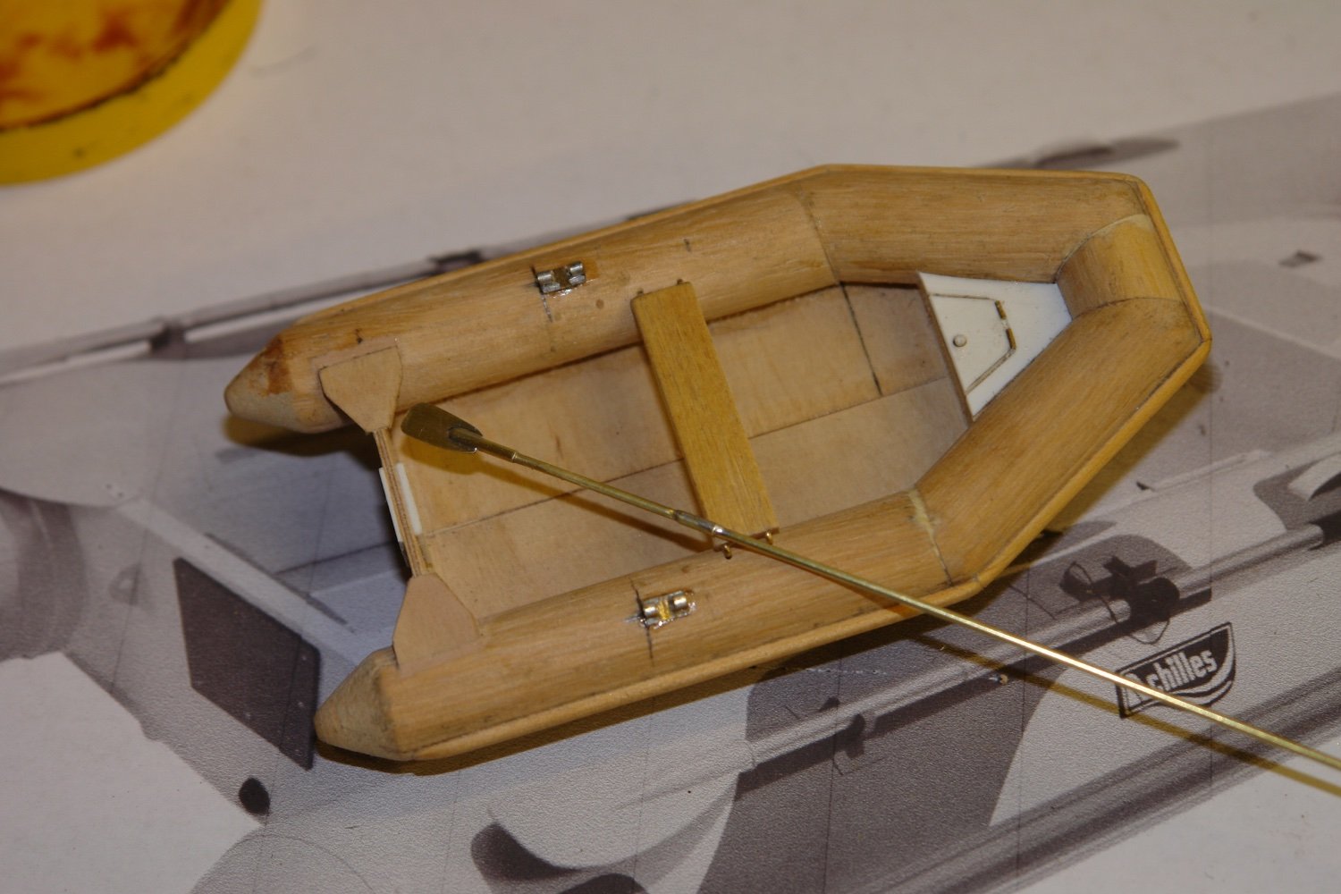
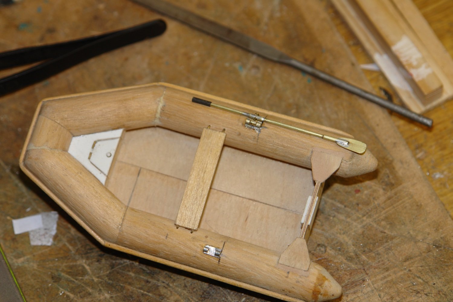
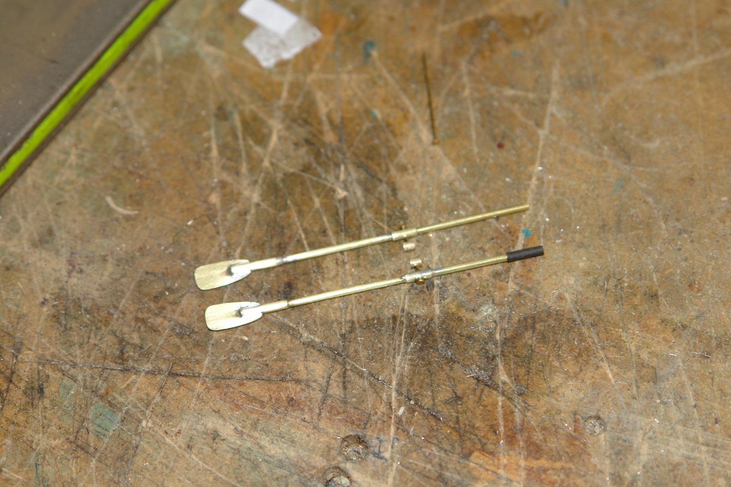
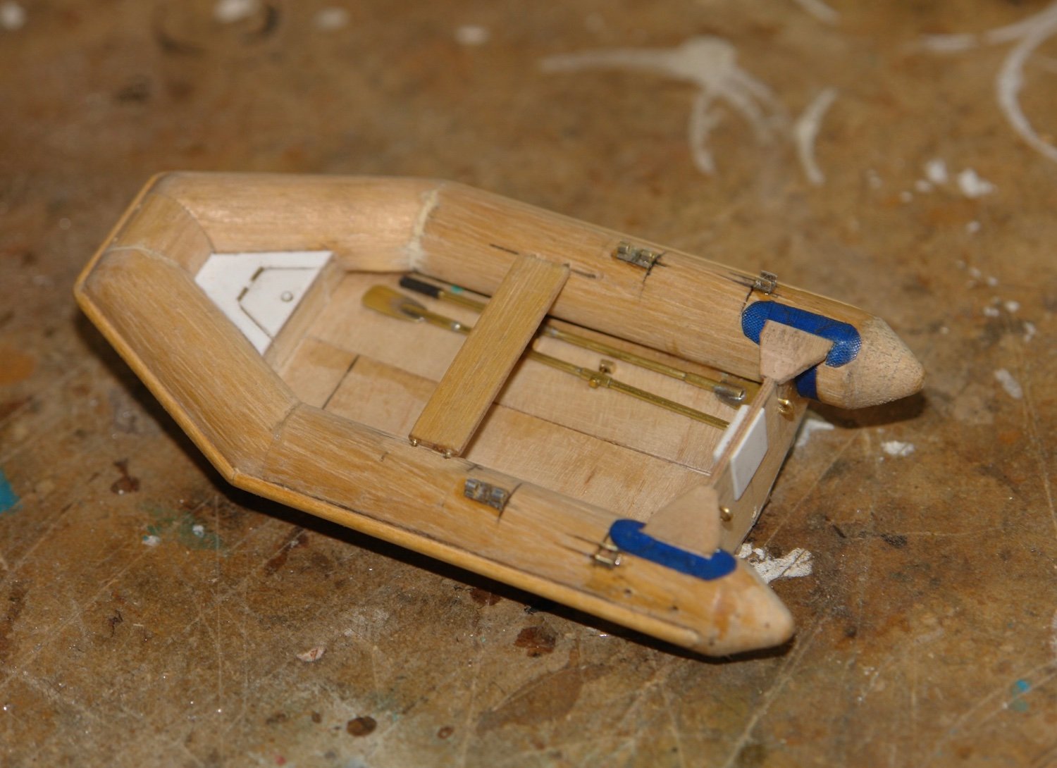
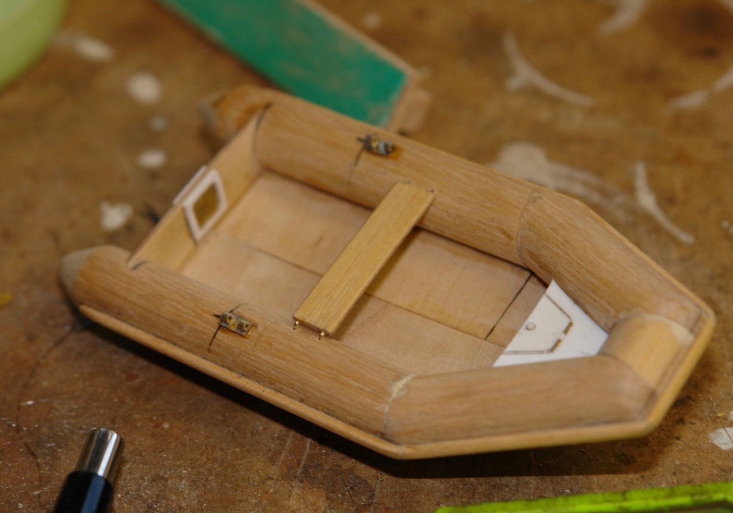
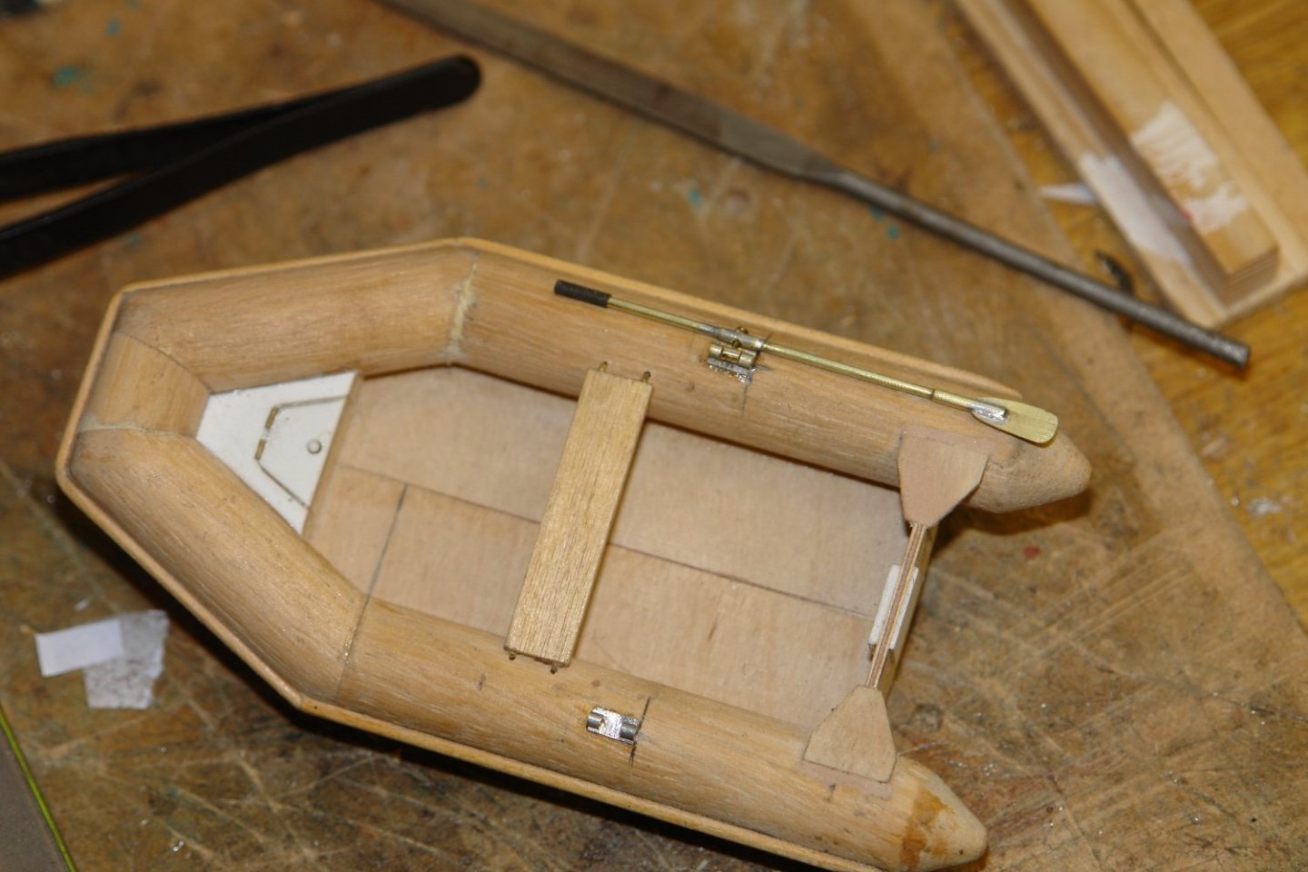
Thank you Tom, Veszett, Mike, Hakan, Andy and Gary for all your contributions and as always thank you to all my other visitors. I continued on with the RIB. The rowlocks were made from small bore tube soldered to a strip of brass. The middle of the tube was then removed. The seat was also made - pinned into the the sides with bent brass wire. I then started to make the oars from brass rod, brass tube and thin brass sheet. Here the blade is inserted into a slot in the .040" brass rod thickened with brass tube. Also the rod is thickened at the rowlock to take the rowlock shaft. Braces that strengthen the transome were also attached. The blades were soldered in and the rowlocks were attached. The handles were made from heat shrink tube. The oars are stowed along the RIB sides as per the next image. Clips that support the blade end of the oars were made and attached. They were made from tube attached to brass strip as per the rowlocks. The top of the tube was then filed away to form the open jaw. The fabric of the inflatables is reinforced in high load and high wear areas. I started to attach fabric tape to simulate these areas.


-
I think it is a common symptom of exposure to this forum and is more severe among micro modellers. I prescribe a good bottle of wine and a night off. Was it quilted or just the standard stuff 😀. Nice little boat. What is its actual length and beam?
-
Yes - I saw a very good video (with survivor interviews) several years ago. If my recollection serves me well (which isn't always the case) she could have arrived early but choose to delay entry to "arrive on time". Am I fantasising???
- 454 replies
-
- 1
-

-
- Union Steamship Company
- Stepcraft 840
- (and 3 more)
-
Lou You are walking a tight rope. Scotch is indeed a drink and Scot is a person. They get very touchy about the distinction north of the boarder. On the other hand you may indeed have a lot of scotch in your ancestry - I remember all of those western bar scenes.
- 454 replies
-
- 1
-
-
- Union Steamship Company
- Stepcraft 840
- (and 3 more)
-
Nils - Maybe she deserves a new one😀 With 6 sails I suspect she will look magnificent.
- 180 replies
-
- 2
-
-
- pilot boat
- Elbe 5
- (and 3 more)
-
She is coming along really well Nils. Are you planning to model the full set of sails?
- 180 replies
-
- 1
-
-
- pilot boat
- Elbe 5
- (and 3 more)
-
Hi Dan, that was a very quick start. As I was reading through everything I was starting to think that maybe you were about to complete the build in one post. Fortunately my fears were unfounded and with relief I look forward to the next post.
-
Eye watering - I think I would be considering dry sand sealed in heavy duty plastic bags - but then again I'm a bit of a Scrooge.
- 454 replies
-
- 2
-
-
- Union Steamship Company
- Stepcraft 840
- (and 3 more)
-
Yes my memory was they were sometimes difficult to start but once started they would run trouble free all day long. Unlike the early Japanese outwards that always started but then died at the most inopportune and sometimes dangerous moments. Nice model Andy its takes me back.
-
HMCSS Victoria 1855 by BANYAN - 1:72
KeithAug replied to BANYAN's topic in - Build logs for subjects built 1851 - 1900
Pat Pat, - The best plan would be to post a dimensioned sketch of the part you are trying to make. Then you can challenge us all to have a go at making it, with a prize for the winner. Given the interest you have generated I bet you would get a flood of submissions. What do you think 😃!- 1,013 replies
-
- 2
-
-
- gun dispatch vessel
- victoria
- (and 2 more)
-
You could put a seat in it - just like they do at Peasholm Park in Scarborough. I think that was where I was introduced to ship modelling over 60 years ago. I bet someone knows what I am on about!!!!
- 454 replies
-
- 2
-
-
- Union Steamship Company
- Stepcraft 840
- (and 3 more)
-
Mark - A nice little craft, it will be interesting to see it develop. How do you keep the wood dust out of your keyboard?
-
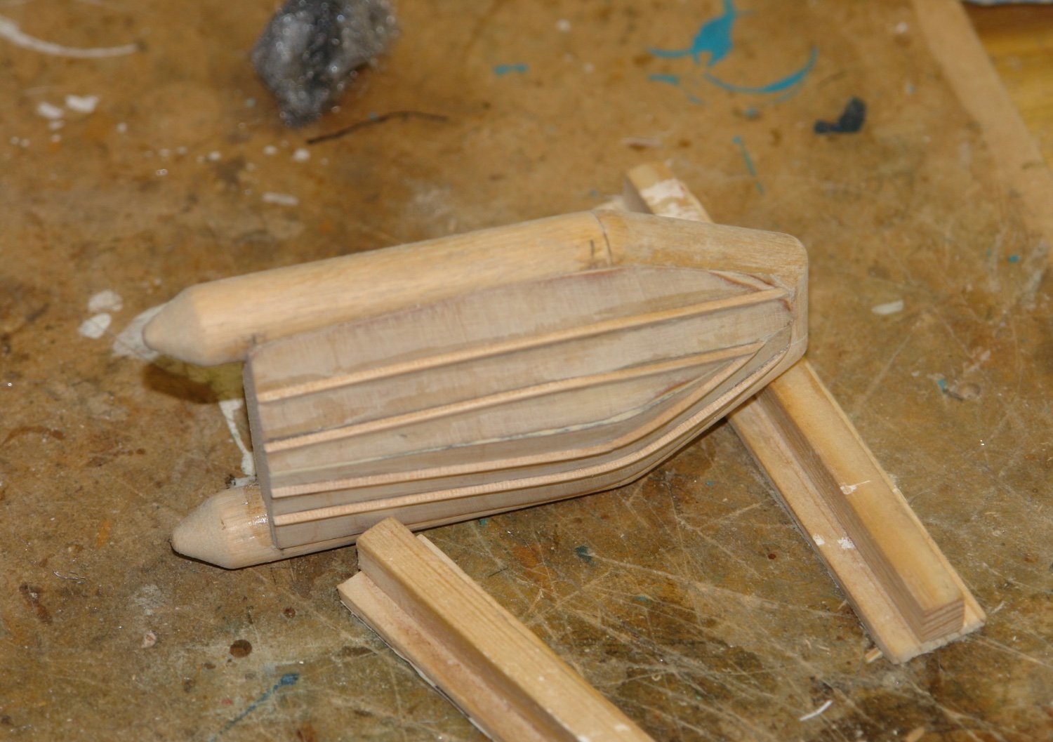
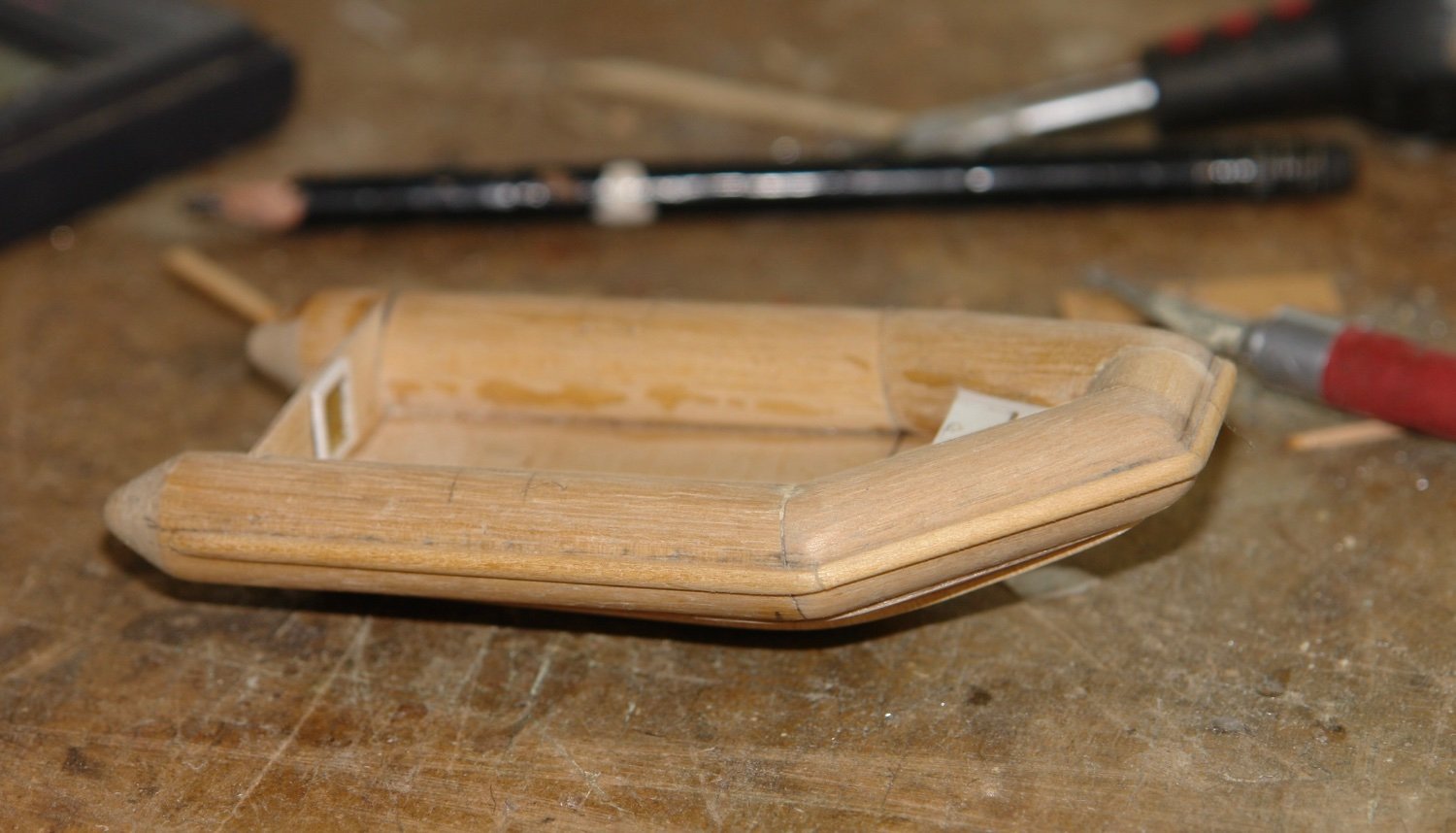
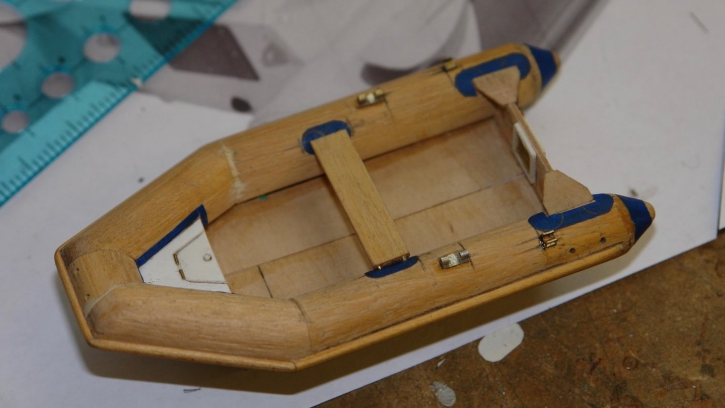
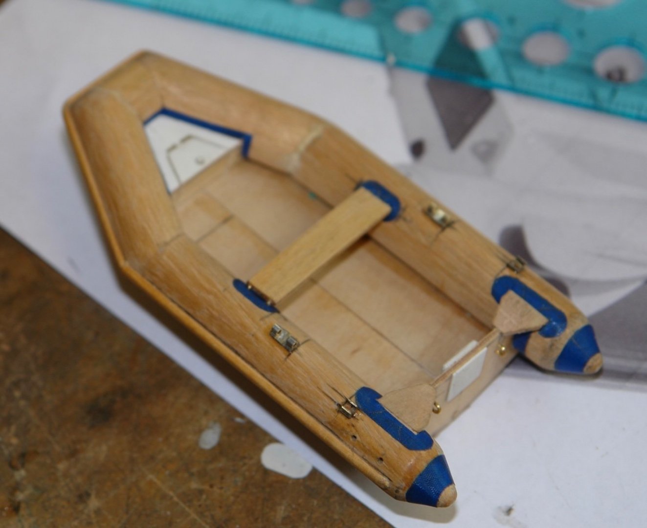
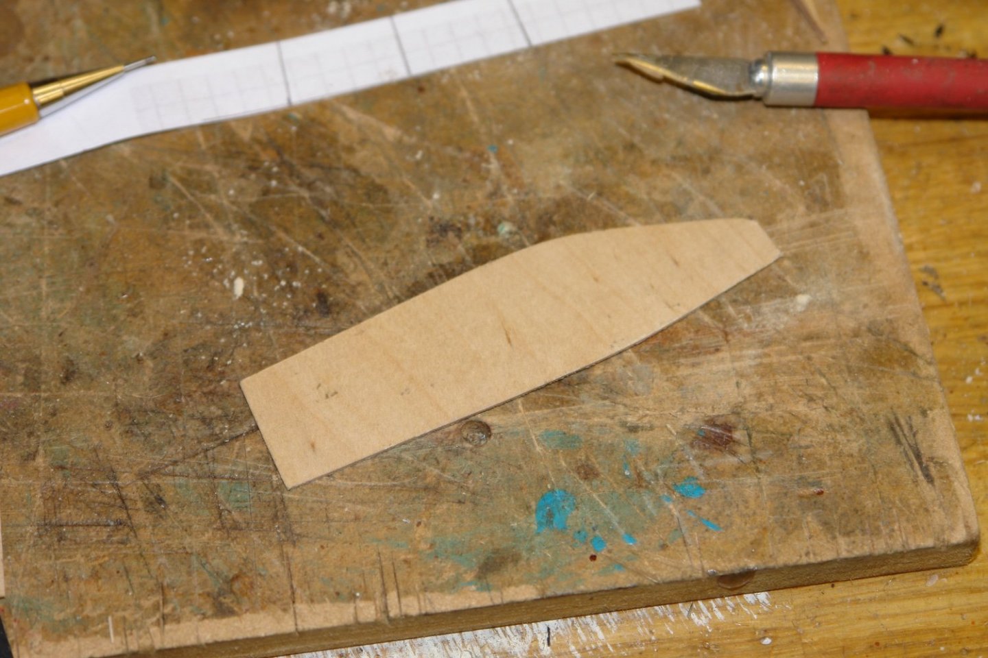
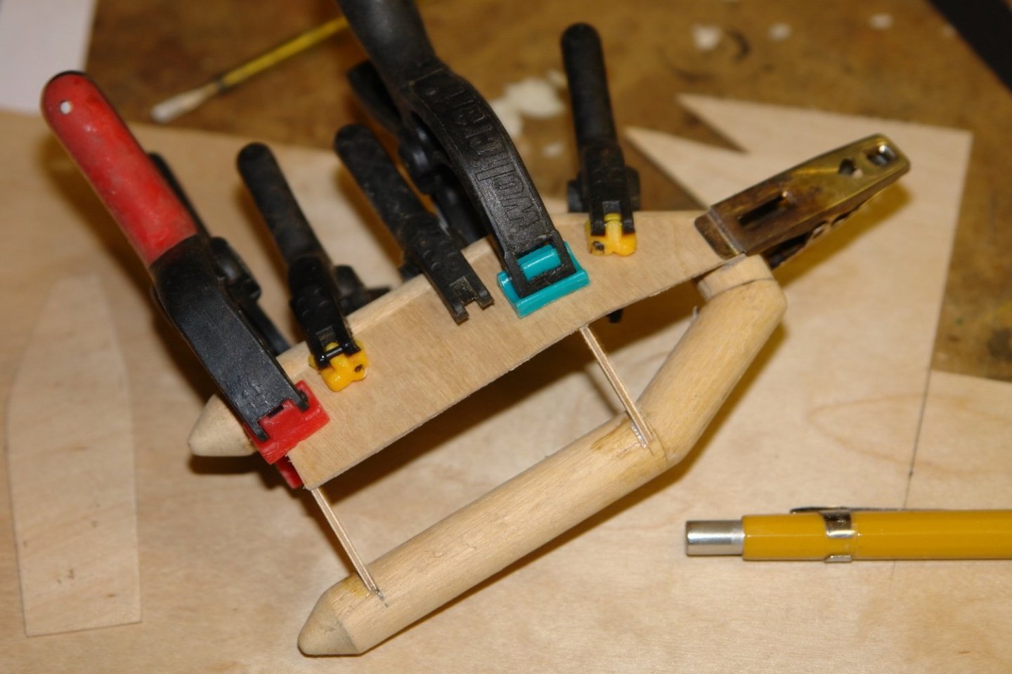
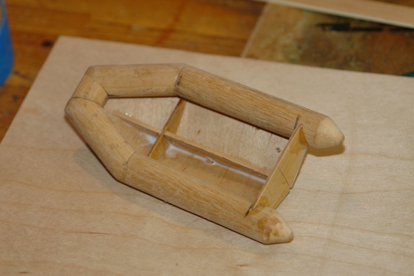
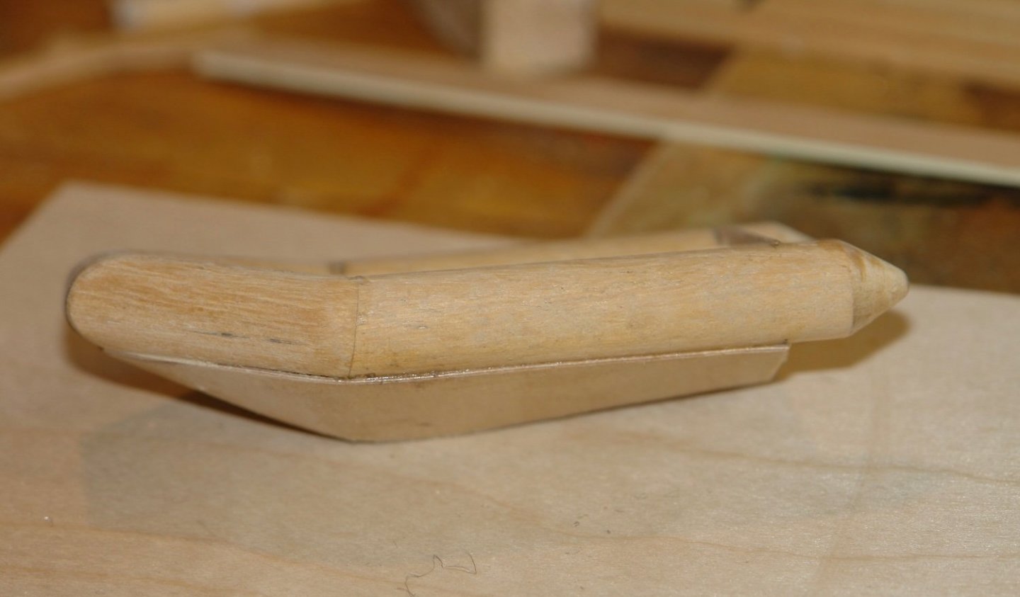
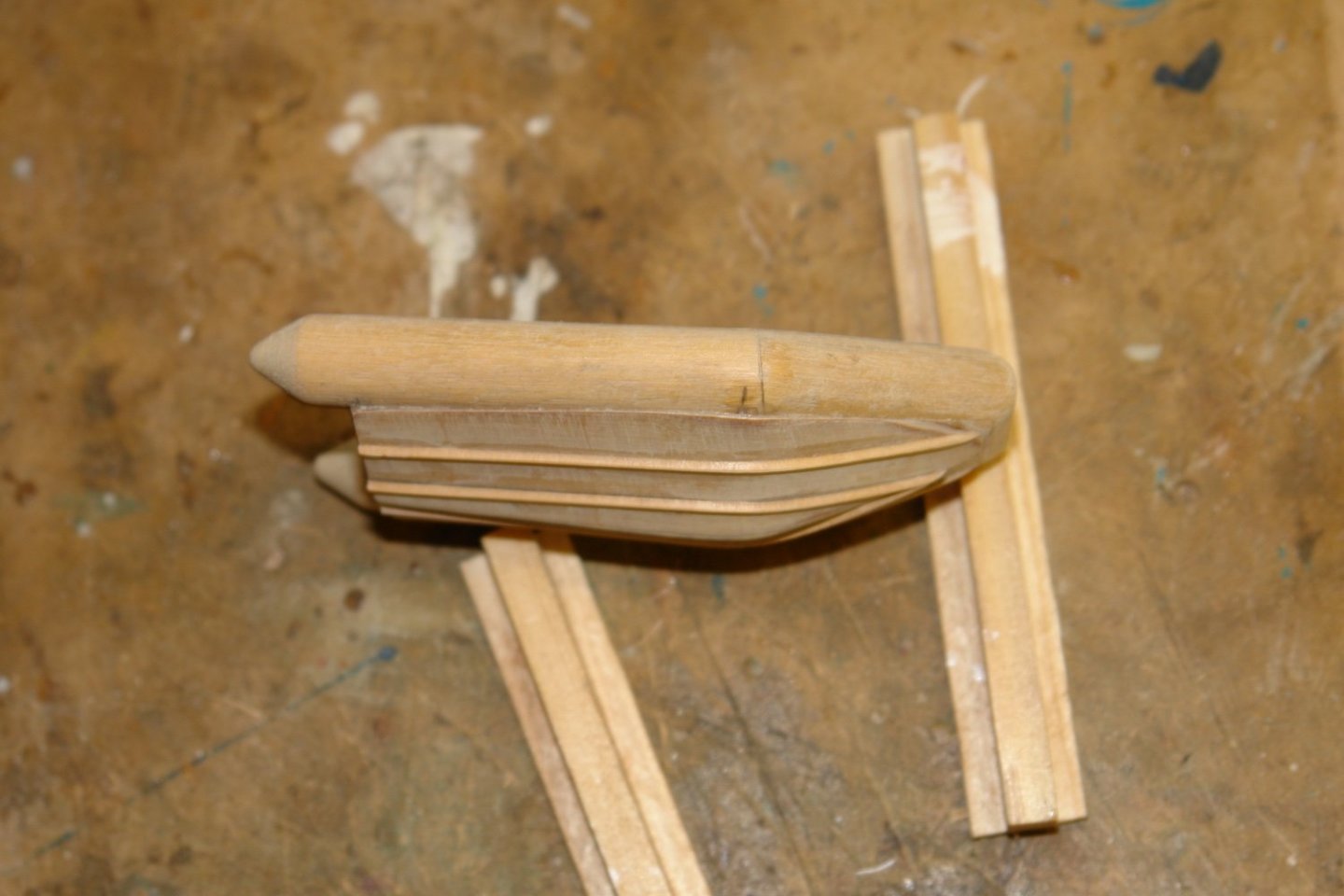
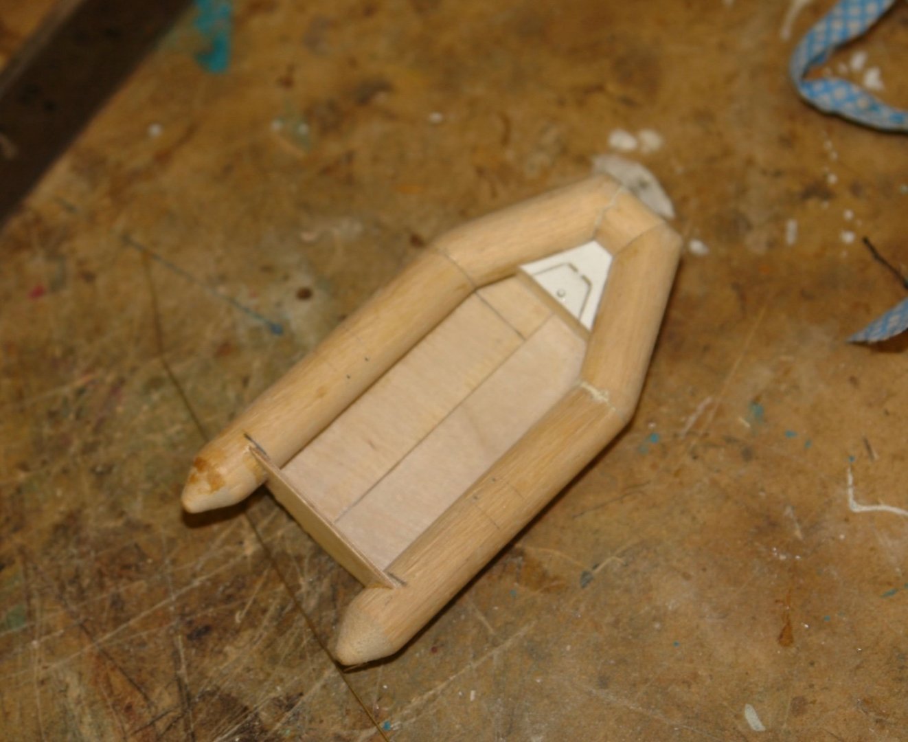
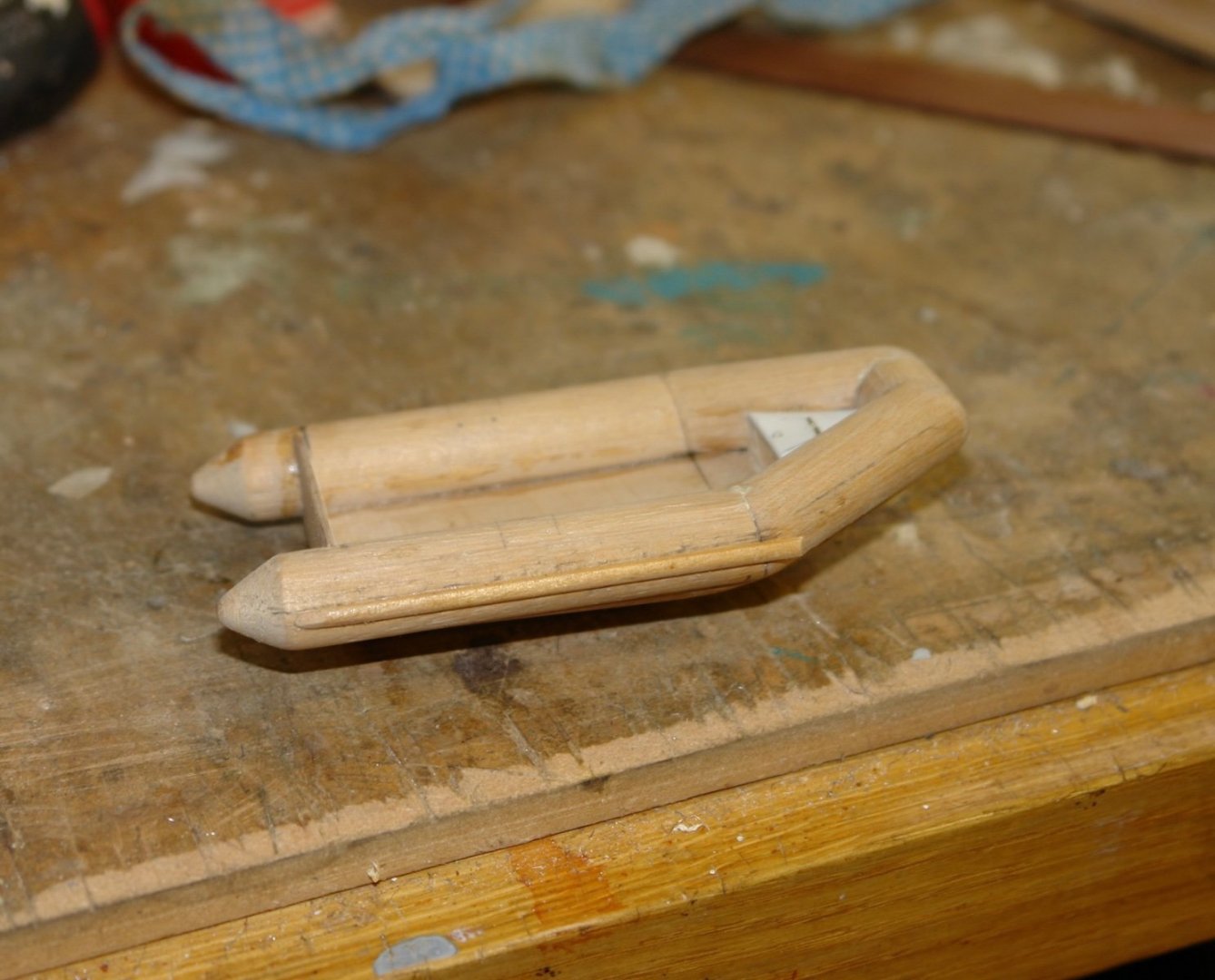
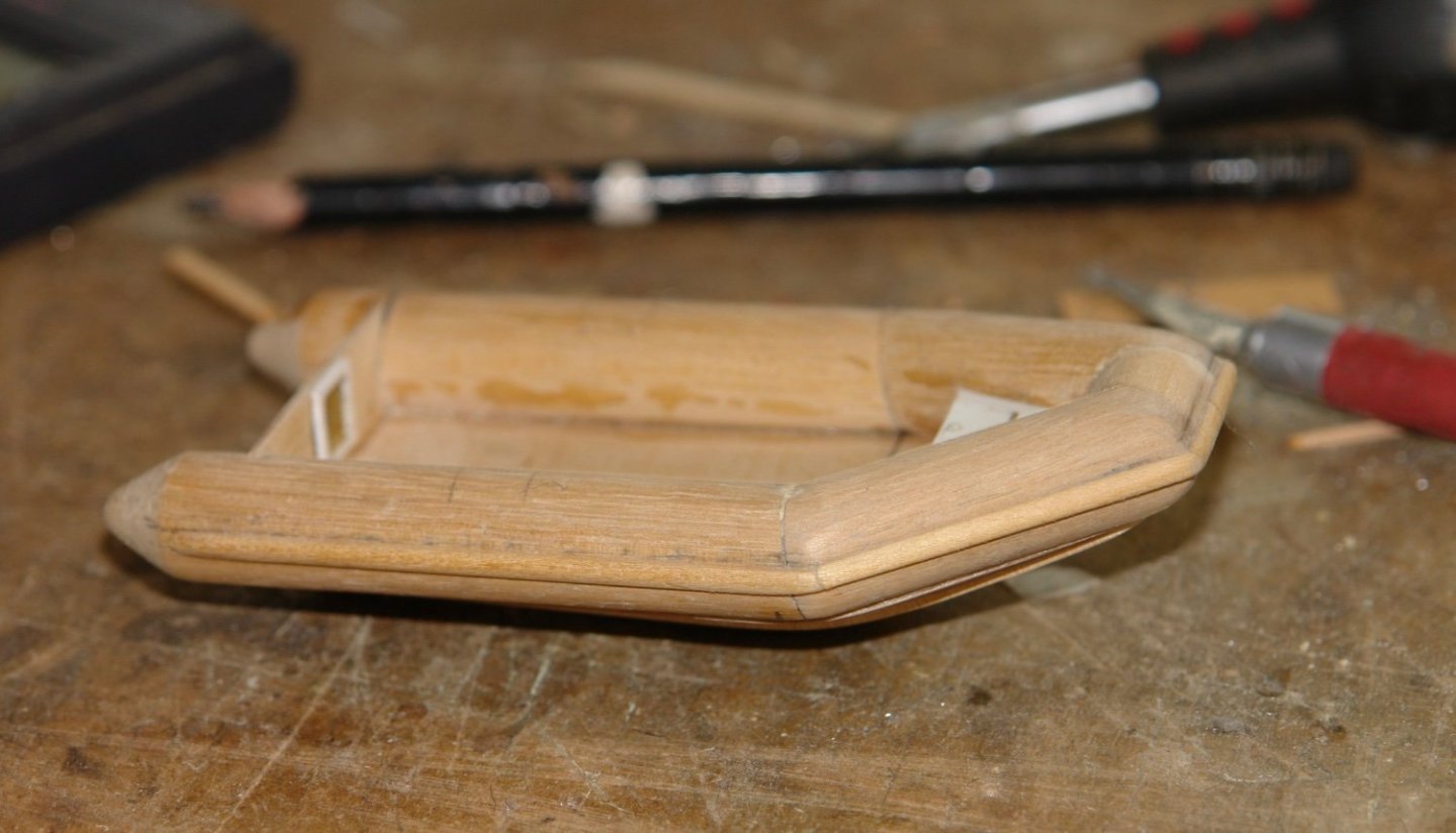
Thank you to everyone for visiting, liking and leaving comments. I have done a git more work on the Rib. I used a piece of card to get the shape of the rigid hull and then transferred the shape to 1/32" ply. The ply was then bent to shape around the transom and mid frame. Then multiple clamps were used to hold the base in place while the PVA glue dried. This was repeated for the 2nd half of the base and a keel was inserted for a bit of extra strength. I then did a bit of light sanding to blend in the edges. Mist Ribs have ridges on their base and these are generally of triangular section. I cut triangular strips and glued these in place. Better quality Ribs have false floors (to get the toffs to the restaurant in their evening shoes - in my sailing days we always frequented resteraunts in our wellies). The floor pieces were cut in 2 halves so they could be inserted below the overhang of the inflatable walls. The toffs also wanted a locker to store the ready use booze for their return journey. The Rib is protected by a rubber bump strip made from a half round piece of scrap wood. The stern also got the mounting plate for the outboard, one of those flashy Yamaha types. Not a Seagull "like what I grew up with". Summer is really getting in the way of progress.

-
HMCSS Victoria 1855 by BANYAN - 1:72
KeithAug replied to BANYAN's topic in - Build logs for subjects built 1851 - 1900
That is an interesting concept. How do you prevent the drill wandering off due to the uneven loading on the drill. Do you need to centre spot a hole with a larger cone than the diameter of the drill?- 1,013 replies
-
- 3
-
-
- gun dispatch vessel
- victoria
- (and 2 more)
-
Eberhard. Amazing that you can achieve any reasonable representation of clinker planks at this scale. I did notice that the exposed edges of some of the planks have slight steps. Is this down to the resolution of the laser cutter?
-
HMCSS Victoria 1855 by BANYAN - 1:72
KeithAug replied to BANYAN's topic in - Build logs for subjects built 1851 - 1900
Pat, there seem to be very few available on the market, which one did you buy?- 1,013 replies
-
- 2
-
-
- gun dispatch vessel
- victoria
- (and 2 more)
-
It certainly is an unusual design of vessel. It will be interesting to see how well it performs, particularly in any degree os swell.