KeithAug
-
Posts
3,986 -
Joined
-
Last visited
Content Type
Profiles
Forums
Gallery
Events
Everything posted by KeithAug
-

Dove by jlefever - 1:48 - Pinky Schooner
KeithAug replied to jlefever's topic in - Build logs for subjects built 1851 - 1900
She has quite an attractive rear, do you know if it severed a particular purpose? -
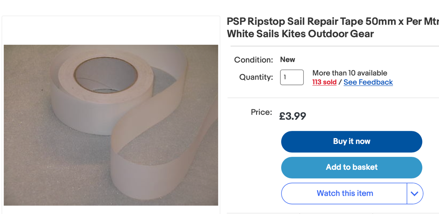
Jon - I find that for jobs like this rip stop tape works really well. Being self adhesive it is easy to work with and it take colour really well - either from acrylic paint or even permanent markers. I find painting before application is easier as it produces really clean edges. Being a fabric tape it retains some texture even when painted giving it a realistic canvas effect.

-
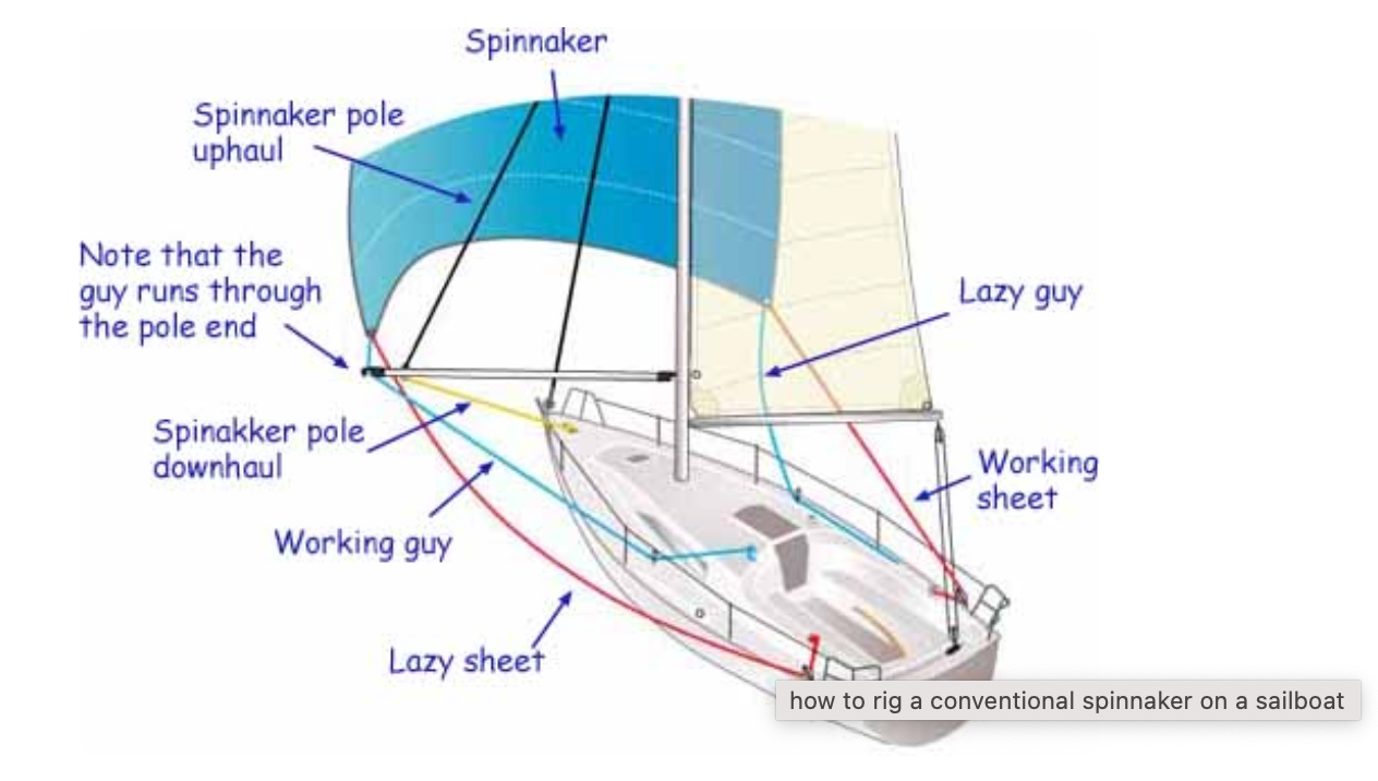
Roger - agreed I have never used the Lazy Guy arrangement. For the record Germania will be rigged with the beak facing upward.
-
Veszett, I think I am back where I started and that is upward and downward facing both have advantages and disadvantages. This is also on the net under "how to rig a spinnaker" and shows the jaws facing downward.
-
I thought i had better look up what the internet says about the orientation of the spinnaker pole beak:- Whisker poles should be flown with the jaws facing down. When taking down a whisker pole, the jib sheet usually wants to drop down-and-out of the end fitting. Spinnaker poles are flown jaws facing up, as the spinnaker sheets usually want to lift up-and-out of the end fitting.
-
Roger My recollection of what the French crew did was as follows:- The boat started to broach. A crew member released the spinnaker sheet to recover from the broach. The sheet ran out completely leaving the spinnaker flying like a giant flag. The crew then tried to take the spinnaker down by lowering the spinnaker halyard. With no ability to control the sail it inevitably ended up in the sea and then disintegrated. Veszett, thank you - I'm sure your expertise vastly outweighs mine.
-
Thank you Tom I had thought that might be the case. The spinnaker pole will be positioned vertically in front of the fore mast. Ready for use.
-
Michael - I could wind one. It would only have to be 1mm OD - that's the size of the wire used to make the latch.
-
Roger, Thank you for reminding me Roger. I remember sailing off the north coast of Guernsey . The (French) boat ahead was flying a spinnaker but we though the conditions were a bit too variable and didn't have ours up. One particularly violent gust panicked the French crew who dropped the spinnaker to avoid a broach. Unfortunately the crew weren't quite ready and as we sailed past the spinnaker disappeared below the hull. A few moments later about half of it reappeared on the the other side of the boat still attached to the sheets. The remainder was presumably wrapped around the keel. They looked very crest fallen. On another point do you recall whether the beak on the end of the spinnaker boom generally faces up or down. I can see advantages and disadvantages with both up and down orientation, but i just can't remember how we used to do it? Thank you Keith, But i will need a wide angle lens. Eberhard, thank you. I suspect it will look less blingy in a couple of years time.
-
Very nicely done, you must do a build log next time.
- 3 replies
-
- 3
-

-
- Gentlemens racer
- Runabout
- (and 4 more)
-
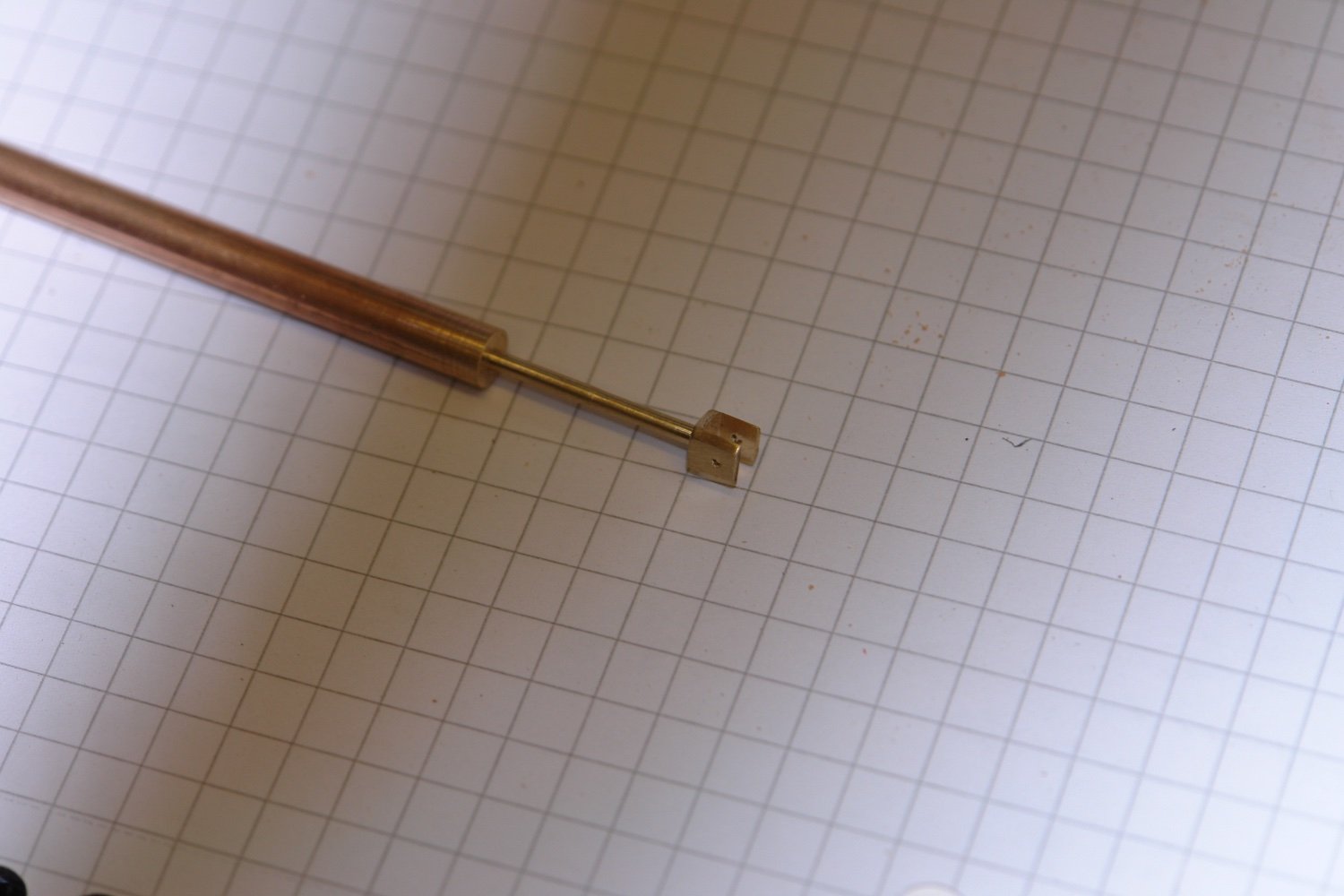
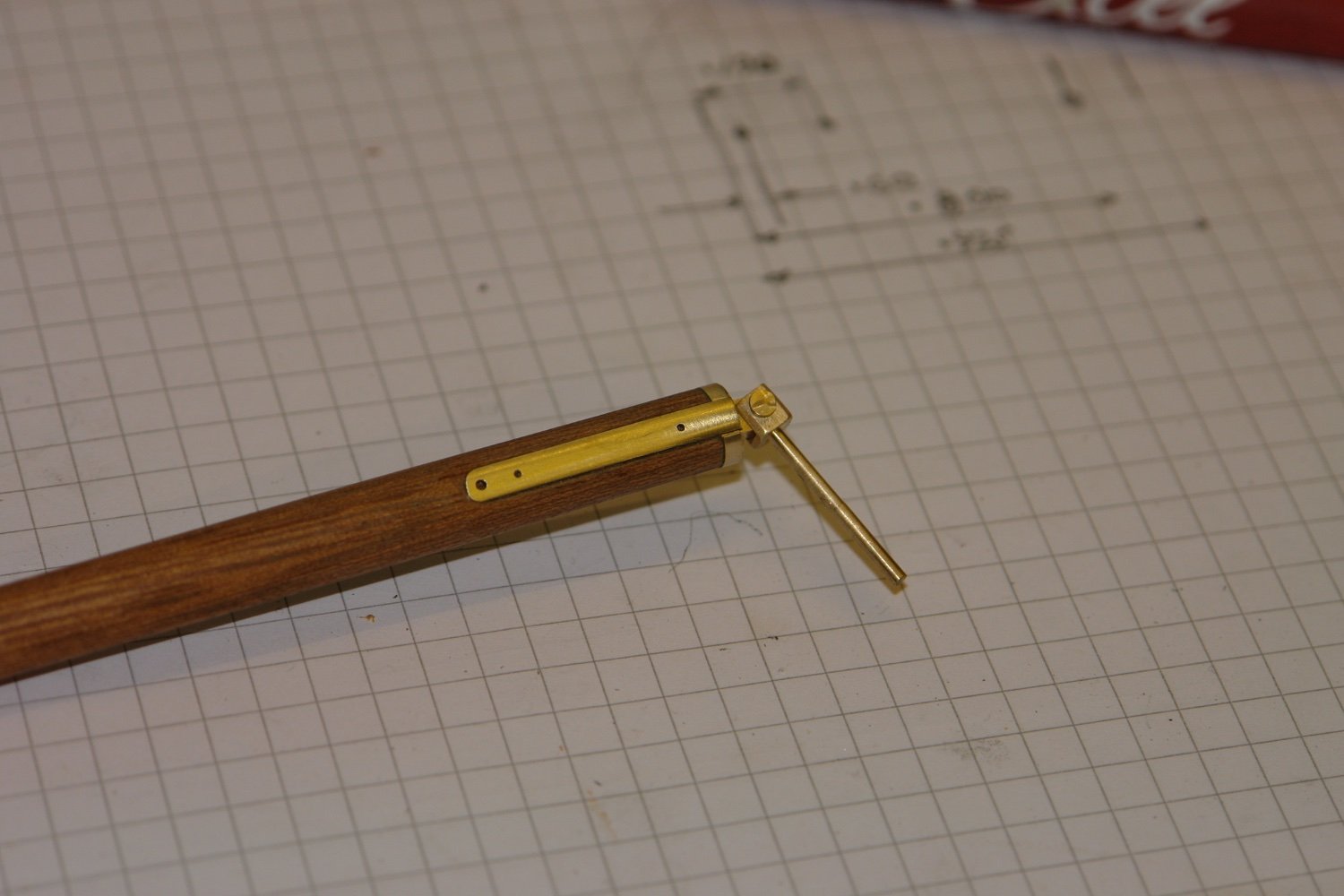
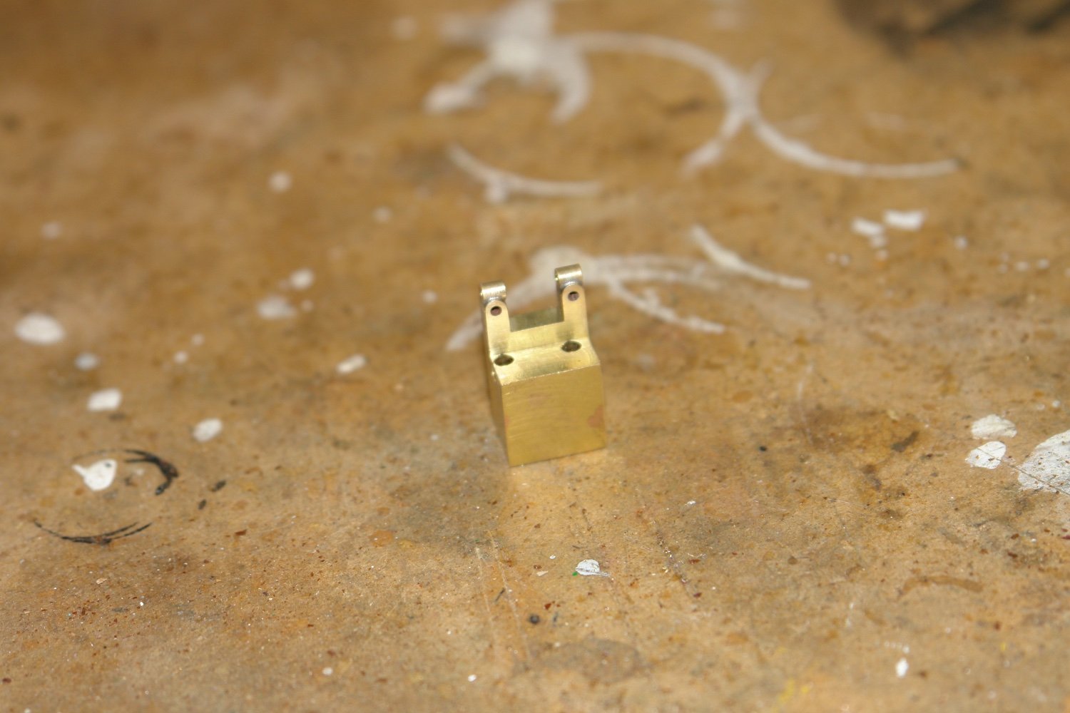
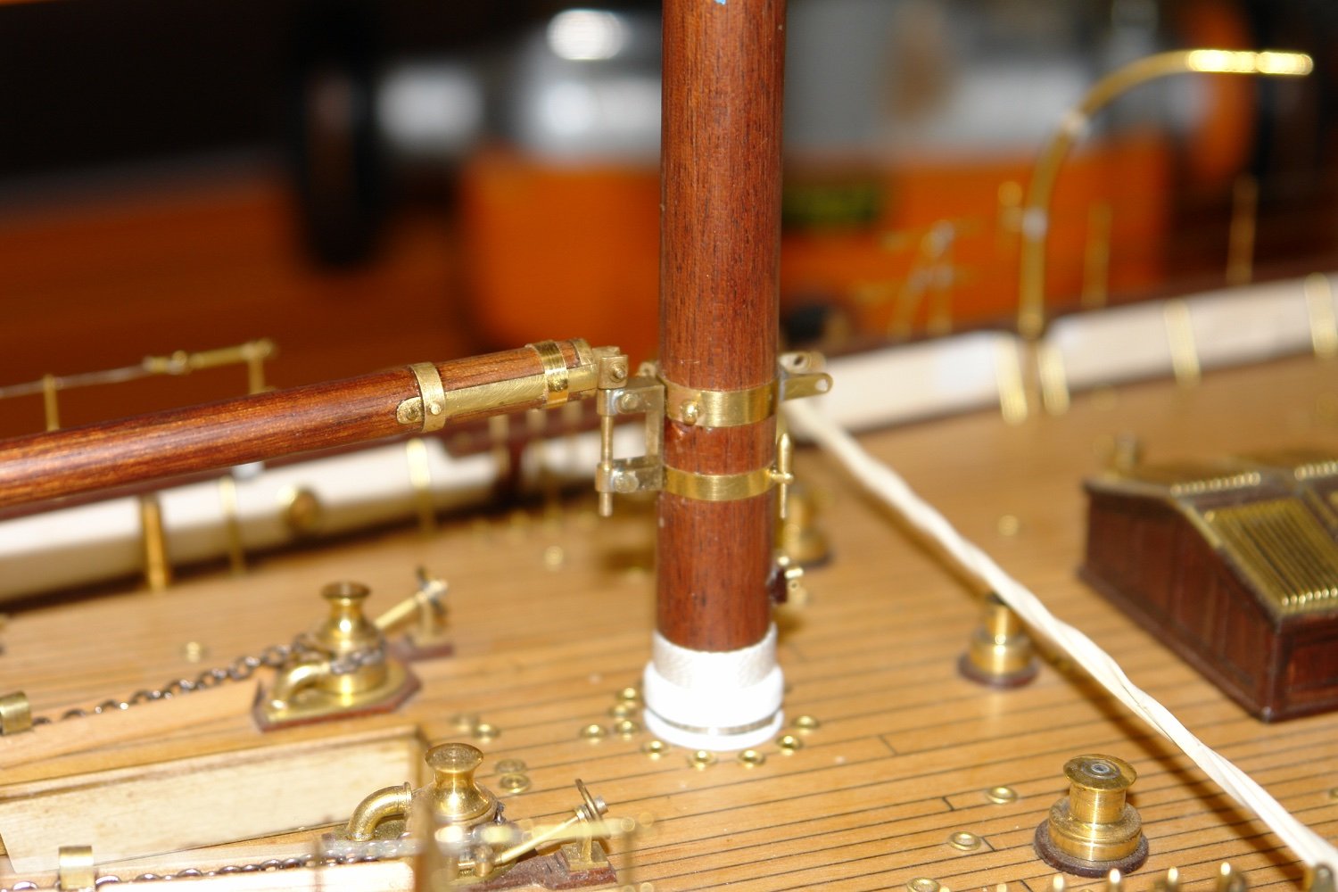
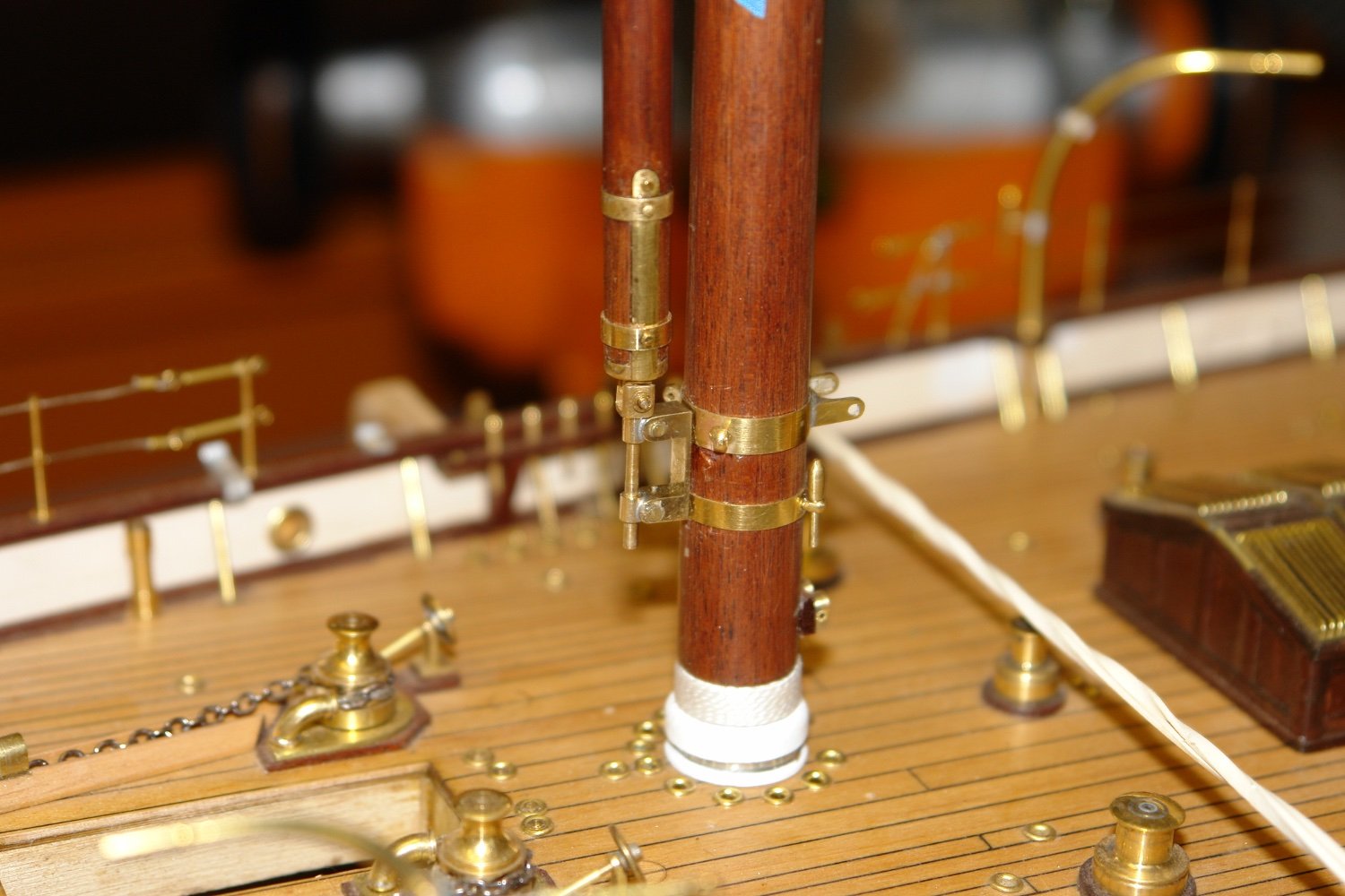
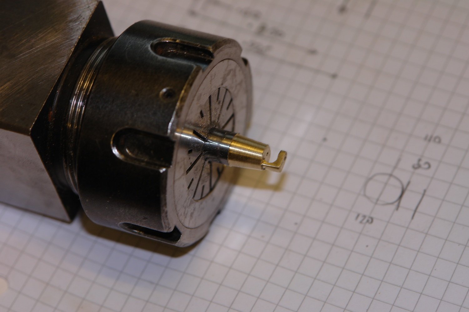
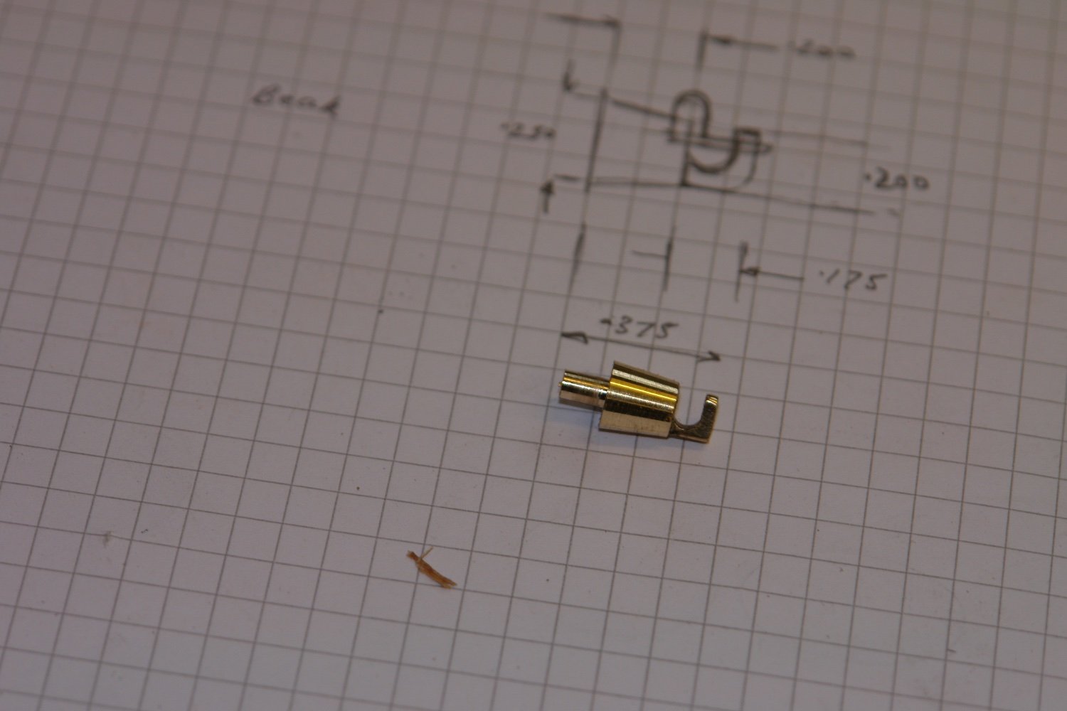
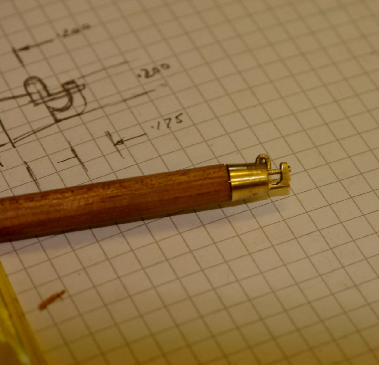
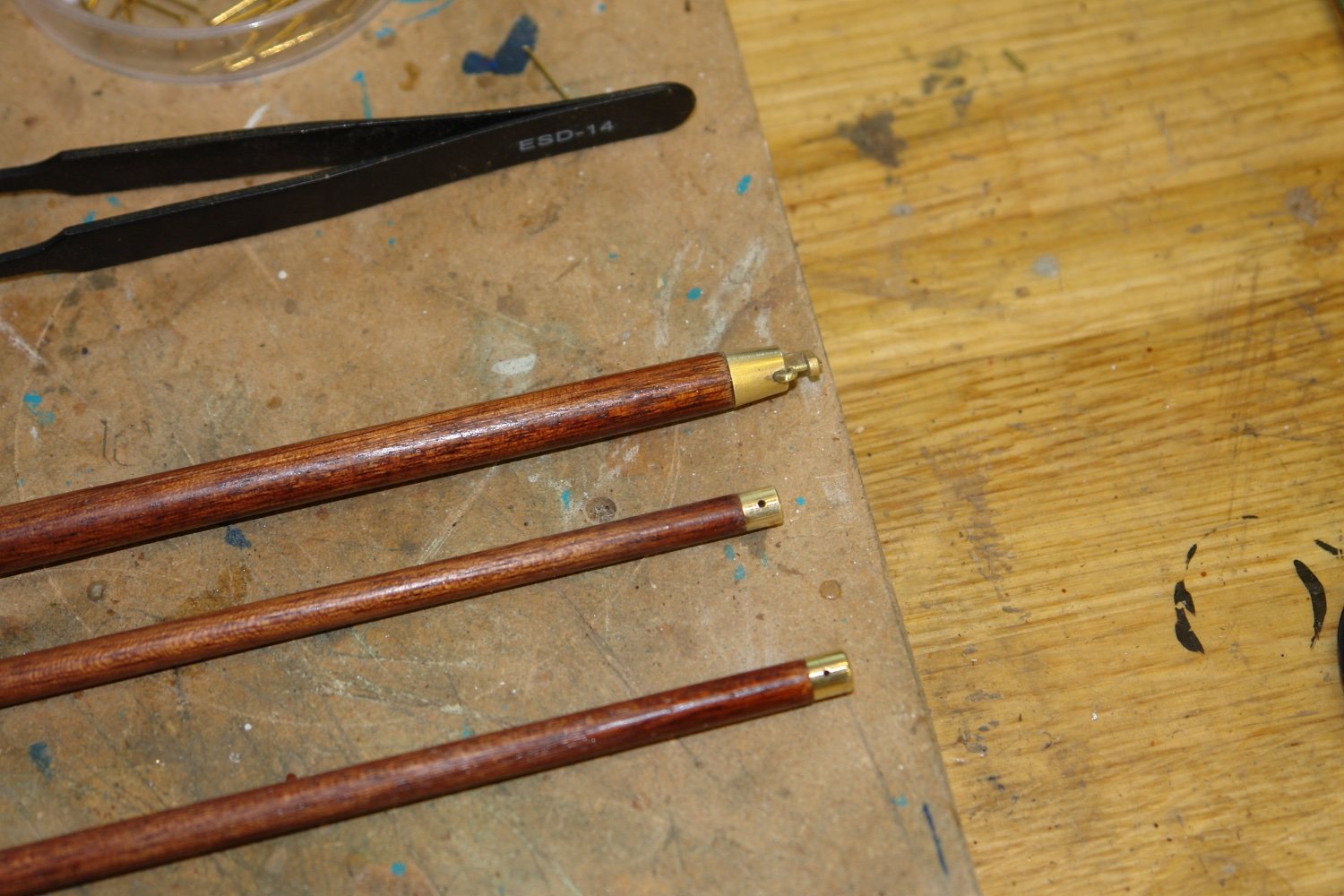
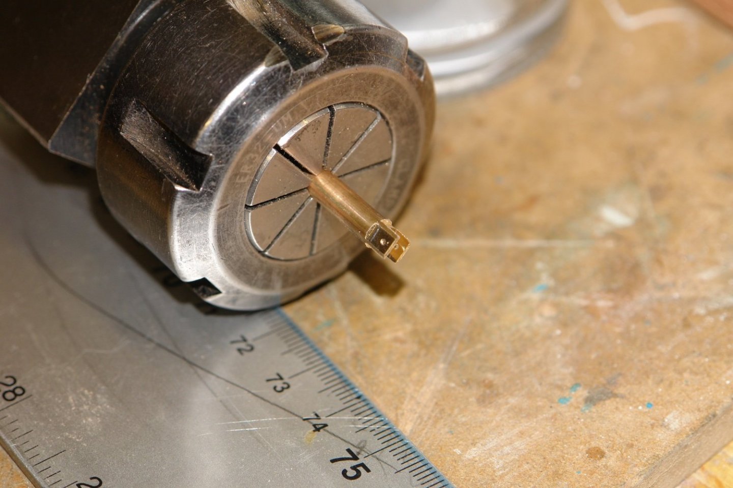
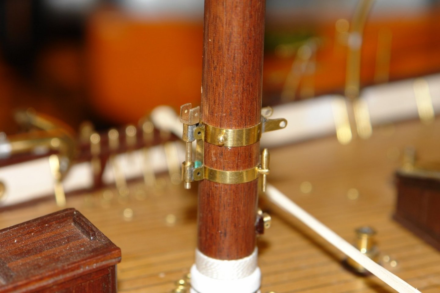
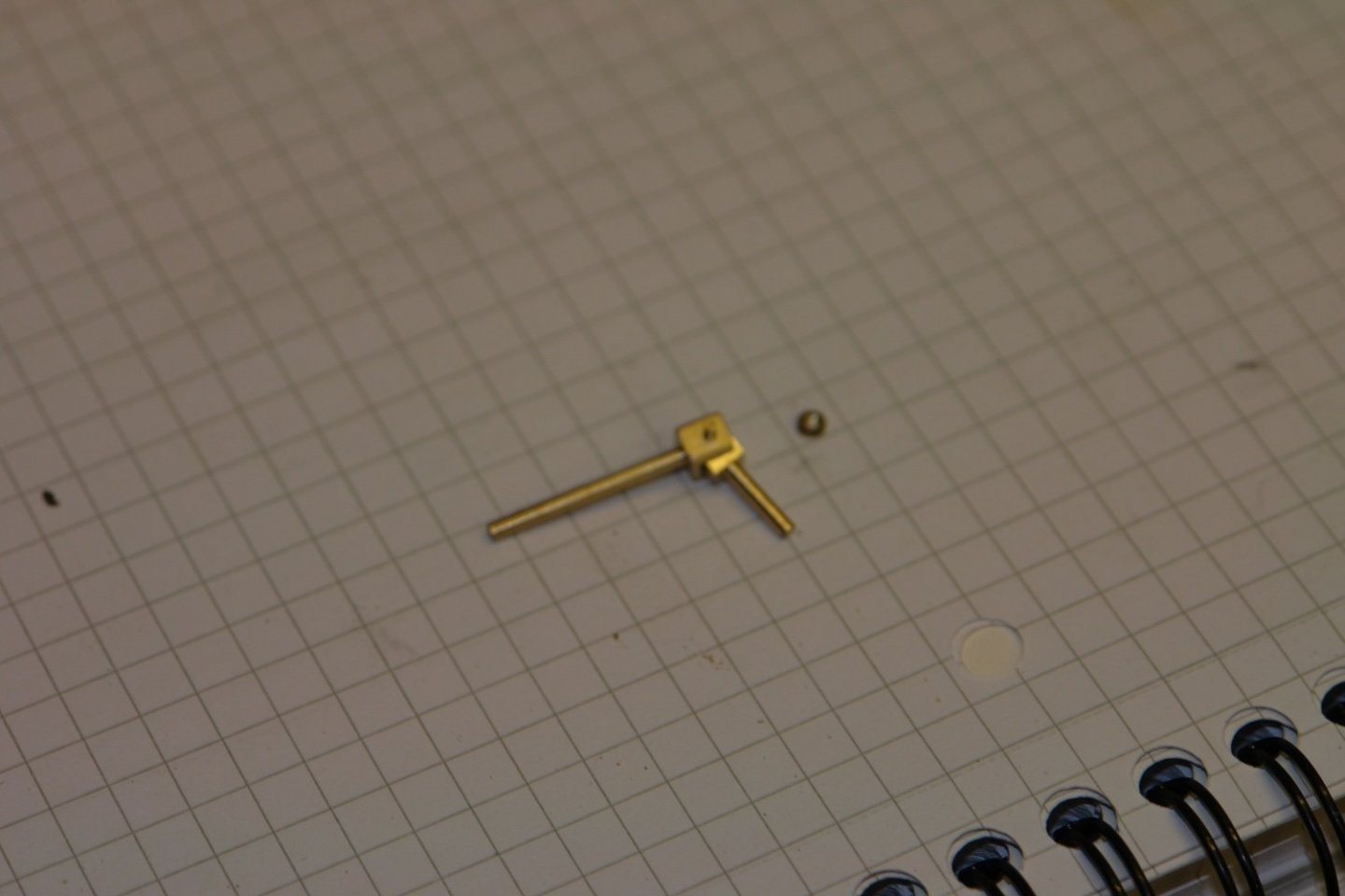
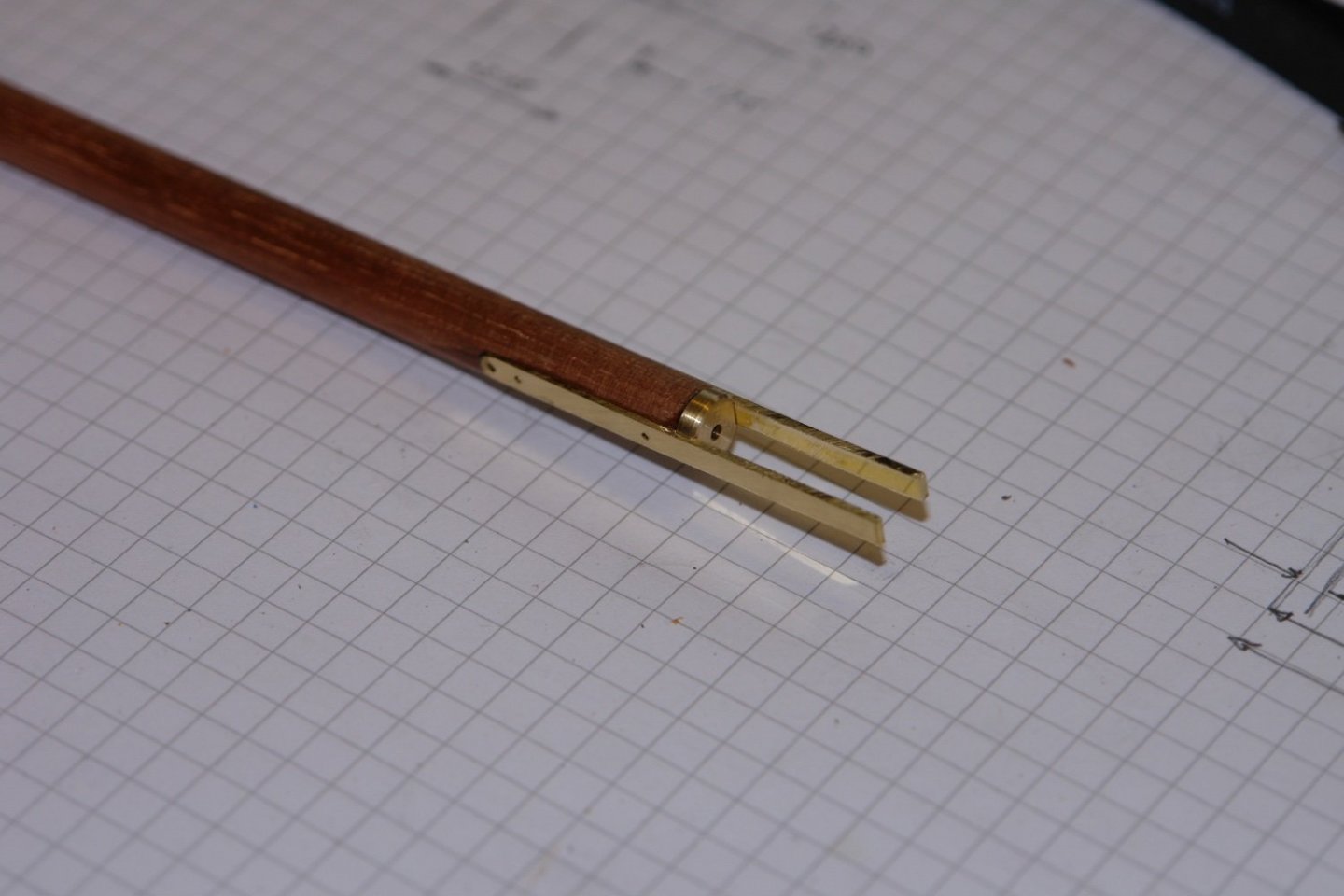
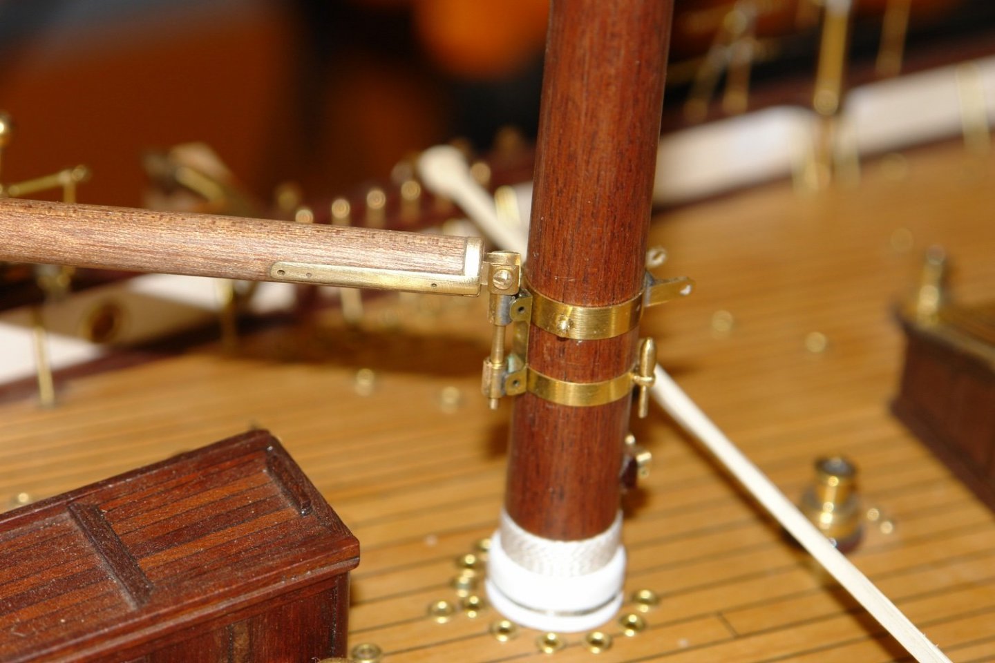
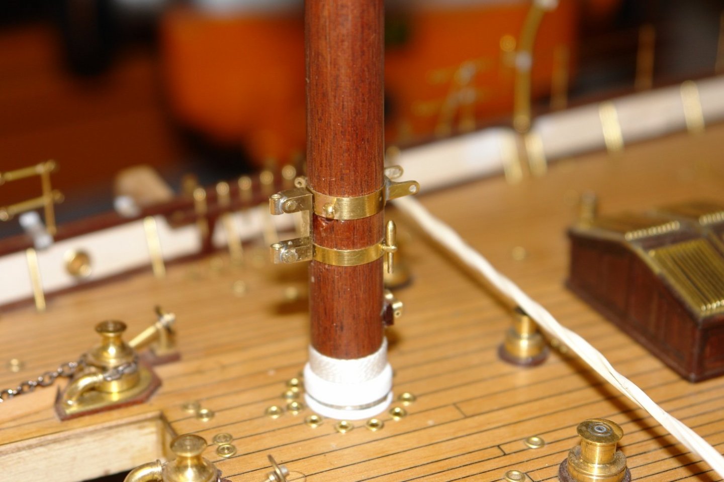
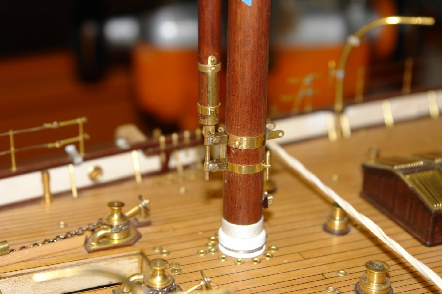
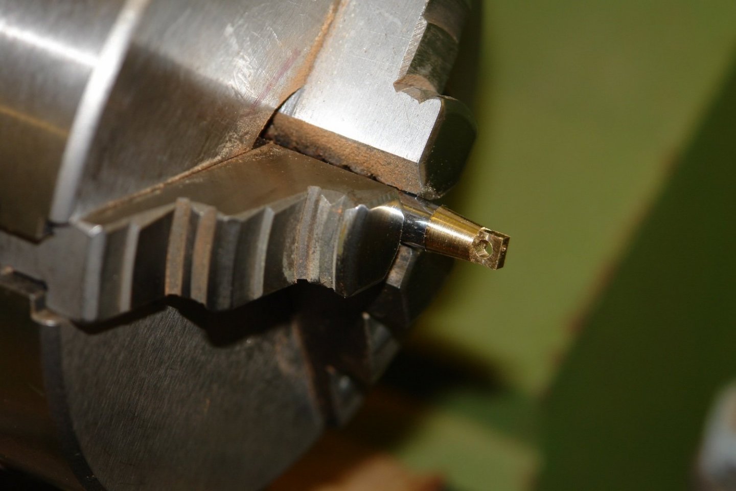
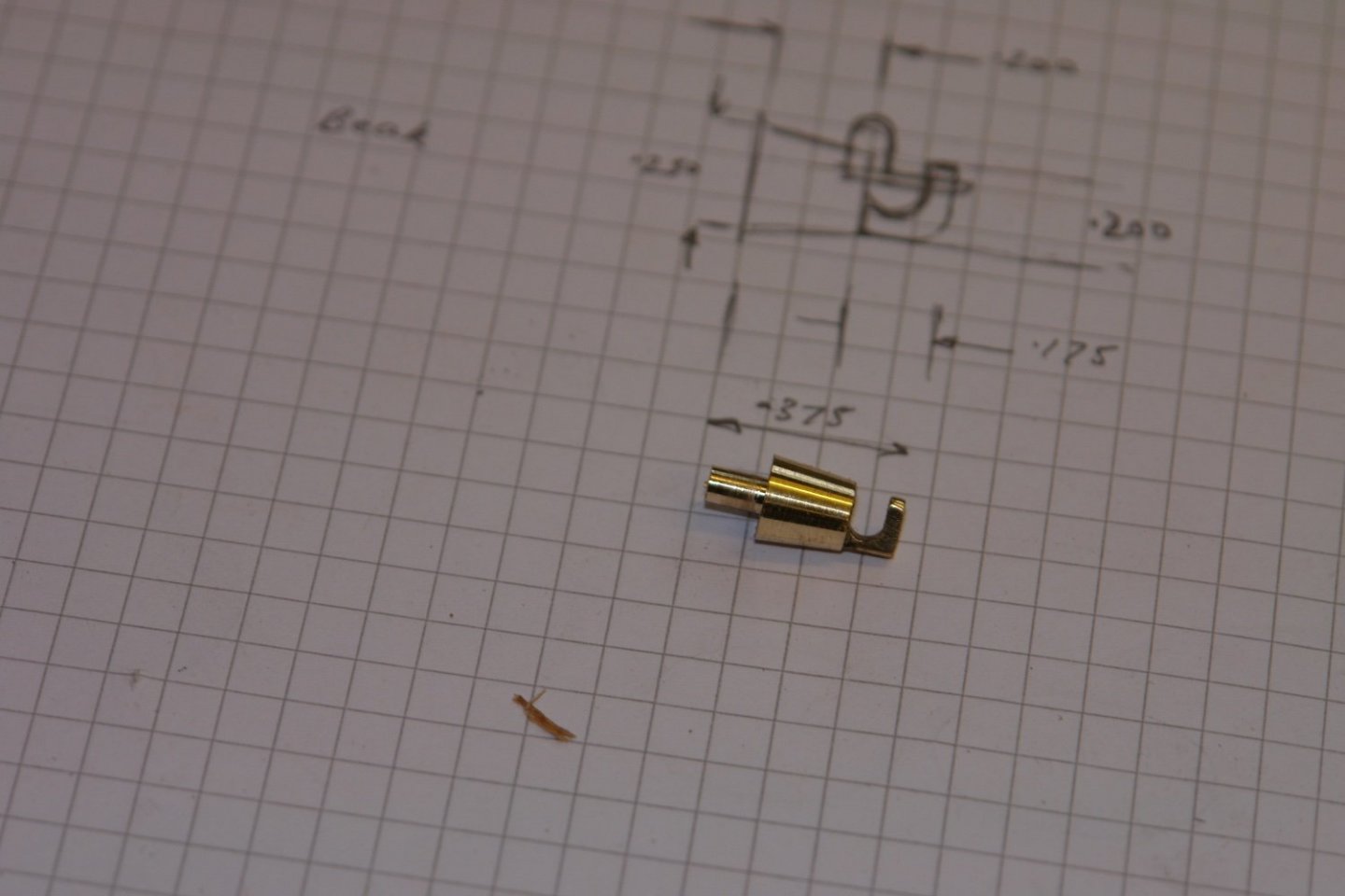
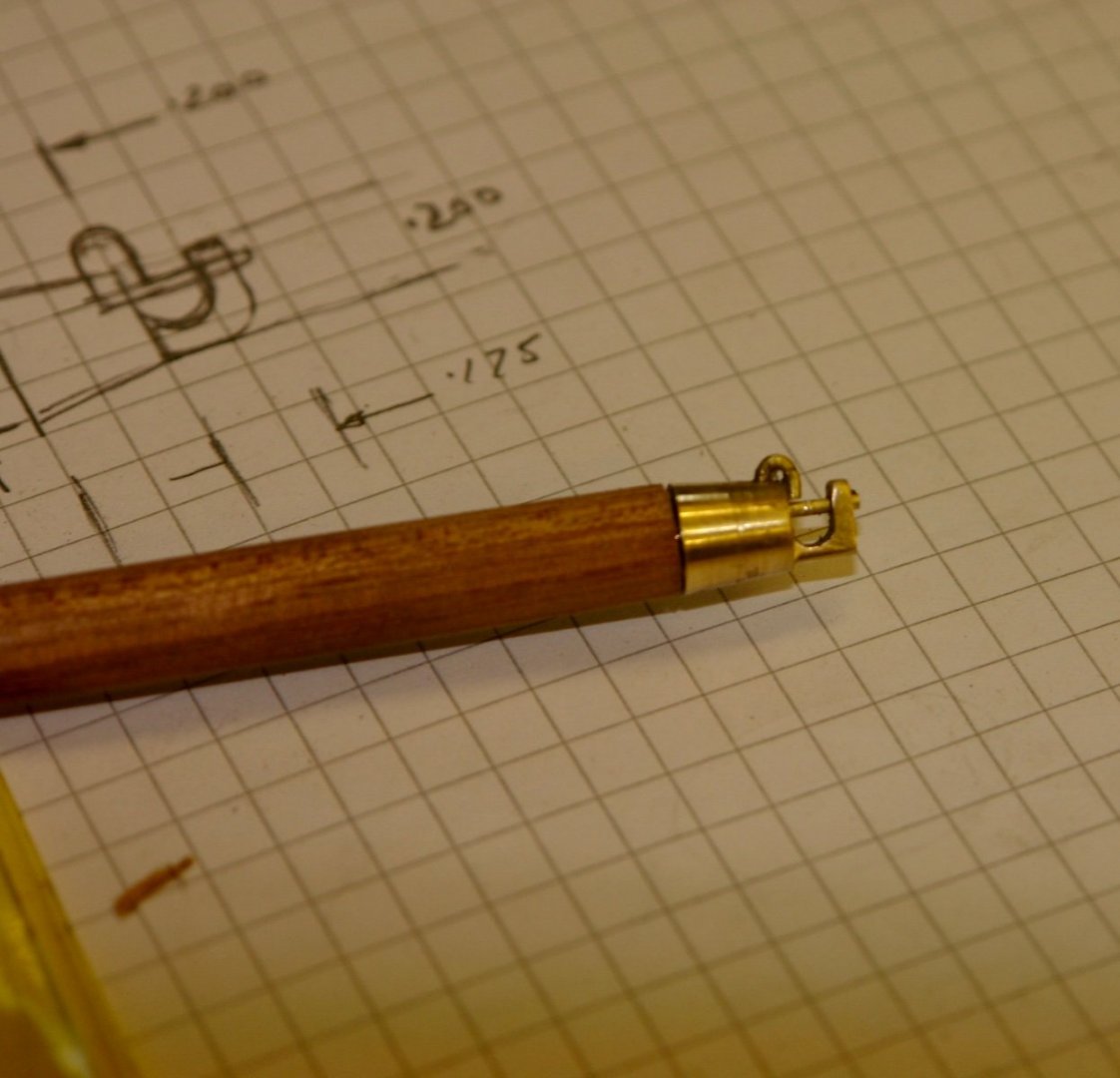
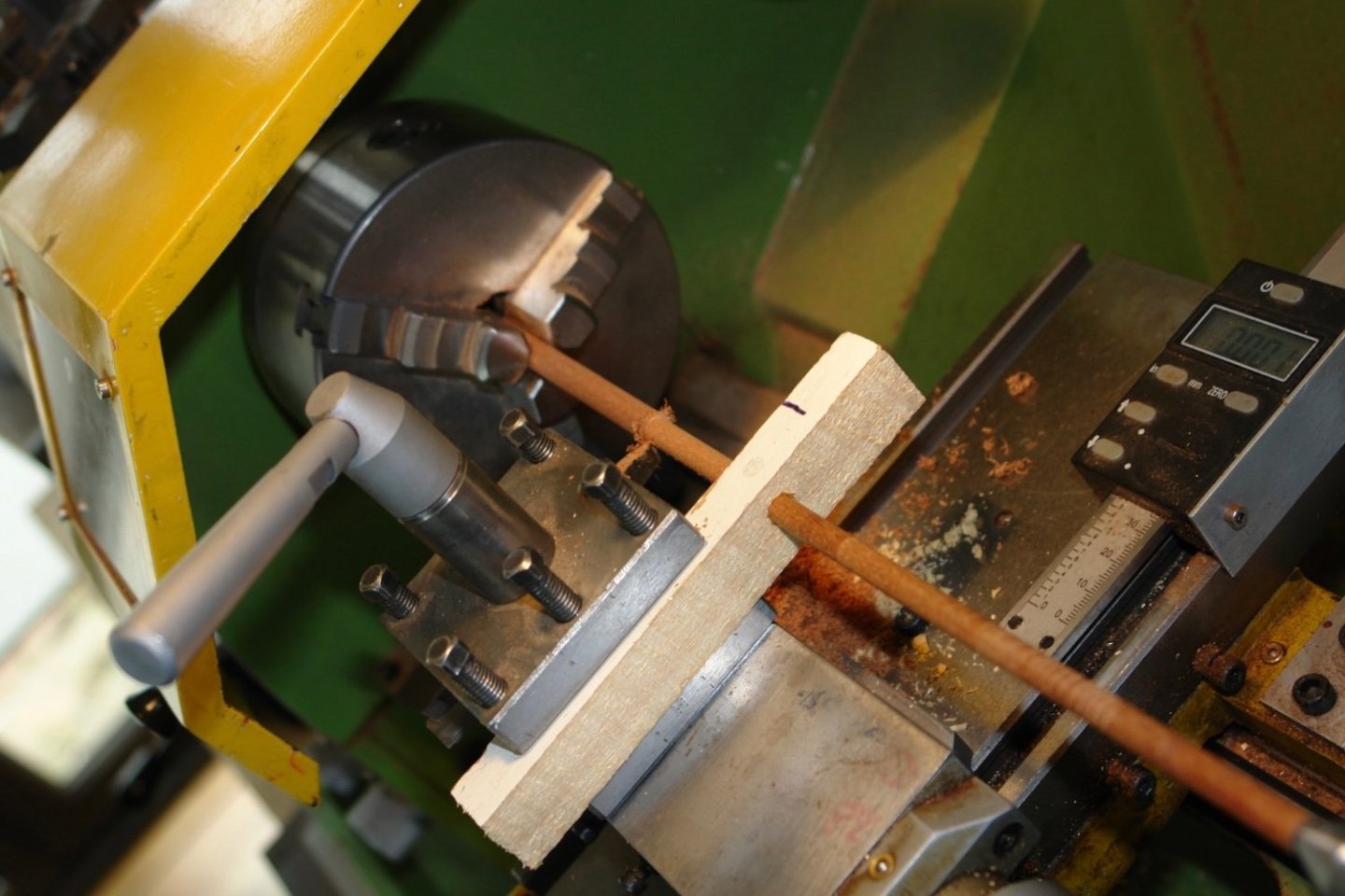
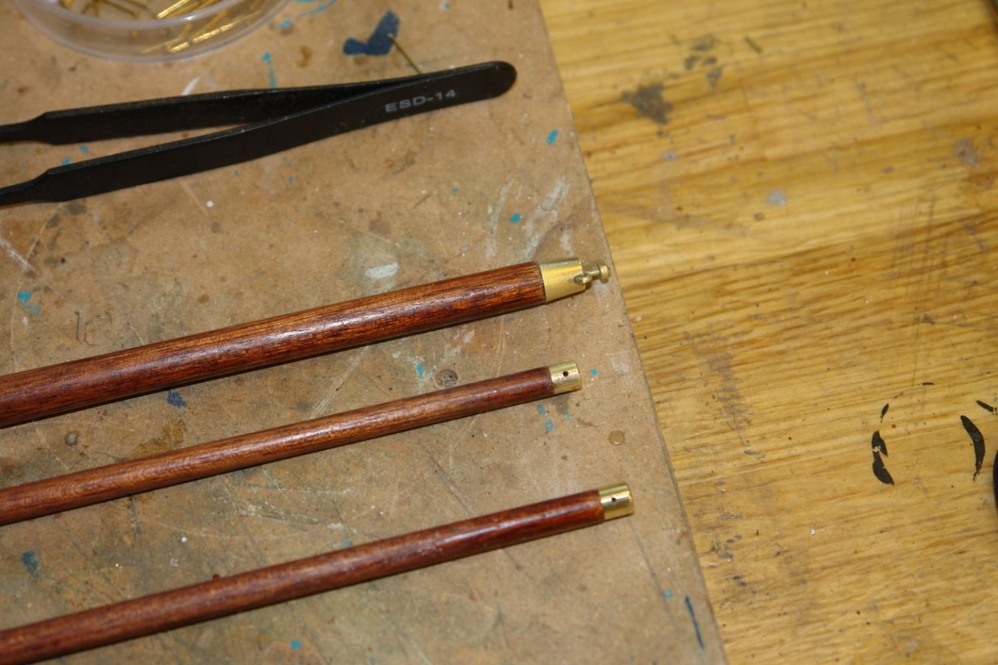
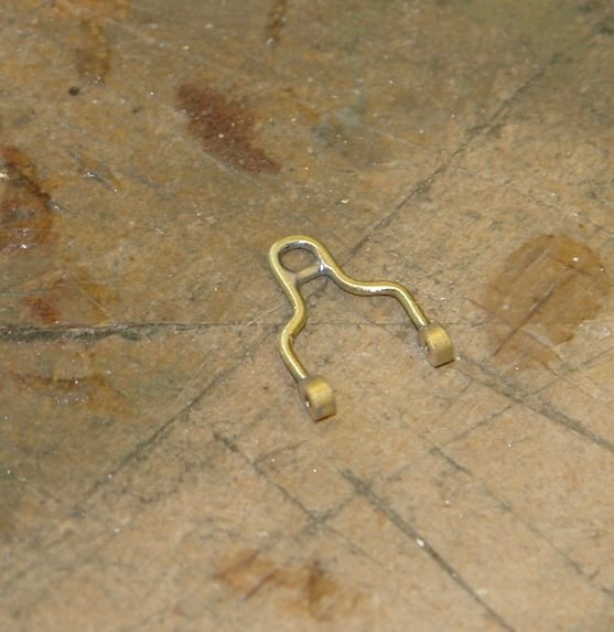
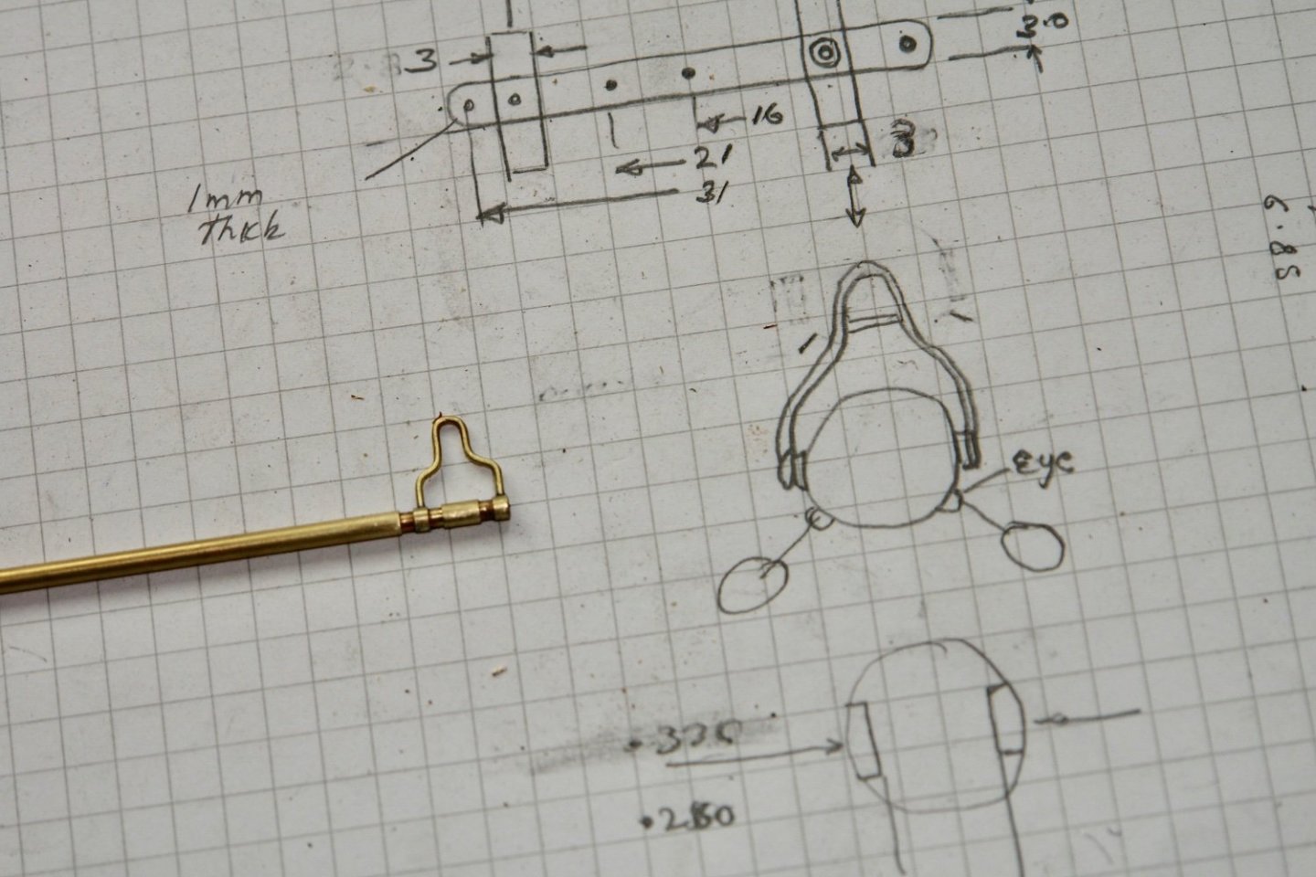
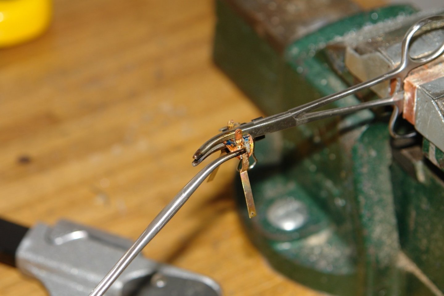
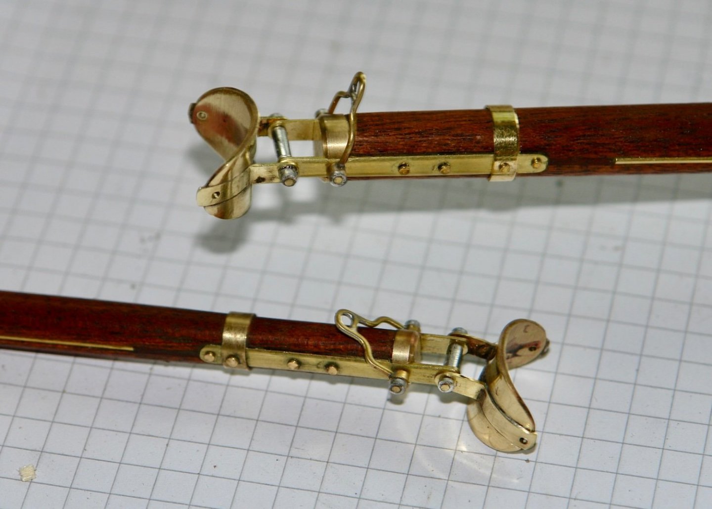
Thank you Phil / Mark I will take on board your comments. I have now made the fore and main masts, the fore and main top masts, the fore and main booms and the fore and main gaffs. None of them are actually complete as sundry strops and sheaves have to be added. That left 3 more spars to be made i.e. the spinnaker boom and the 2 main top sail spars. I started with the spinnaker boom which was turned to diameter and then tapered each end by sanding it in the lathe. Turning down long thin dowels requires the support of a steady. Rather than mount the steady I improvised by putting a piece of wood in the back of the tool post. I then mounted a drill in the chuck and bored a hole in the wood slightly larger than the required boom diameter. I then turned the boom to size using this arrangement. I the proceeded to make the gooseneck fitting for the boom. The boom part of the hinge was much the same as previously described. I then discovered a problem. The mast bracket was of insufficient width. This meant that the boom fowled the mast hoops when in the vertical stowed position. I had to remake this. I then needed to make the beak. I don't have any details of this so I used a typical example from and internet search. The latch doesn't work. I then made the topsail spars. These are simple tapered dowels with end fittings and eyes. That's about it for the masts spars and booms, at least for the moment. Now on to something else - a change is as good as a rest.


-
Hakan - You do remarkably well, i admire your fortitude.
-
Interesting - more "suck it and see" than I might have expected.
-
I wish i had learned CAD. Too late now though for this old dog. It hurts my head trying to work out what they are doing?
-
Michael. In these woke days I'm not sure that I should worry about buying a slinky leather skirt - beautiful travellers. Druxey, Eberhard, Hakan. I have asked my wife to go through her gloves draw but failing that I will try paint.
-
Thank you Druxey, Keith and Mark. I don't think my wife would wear it which is the most telling test. Michael - thank you. I don't really have photos that show that detail but there are a couple of fuzzy shadows that suggest the inside of there saddle has some form of covering so I guess that will be leather. I may try lining the face but it will depend finding something suitable to do it with - perhaps a visit to my wife's glove draw?
-
Phil - Thanks - I had thought that I might take Dremel brushes and soak the subs in CA glue to see if this would reduce bristle loss. Toni - thanks - if the above doesn't work I will give them a try.
-
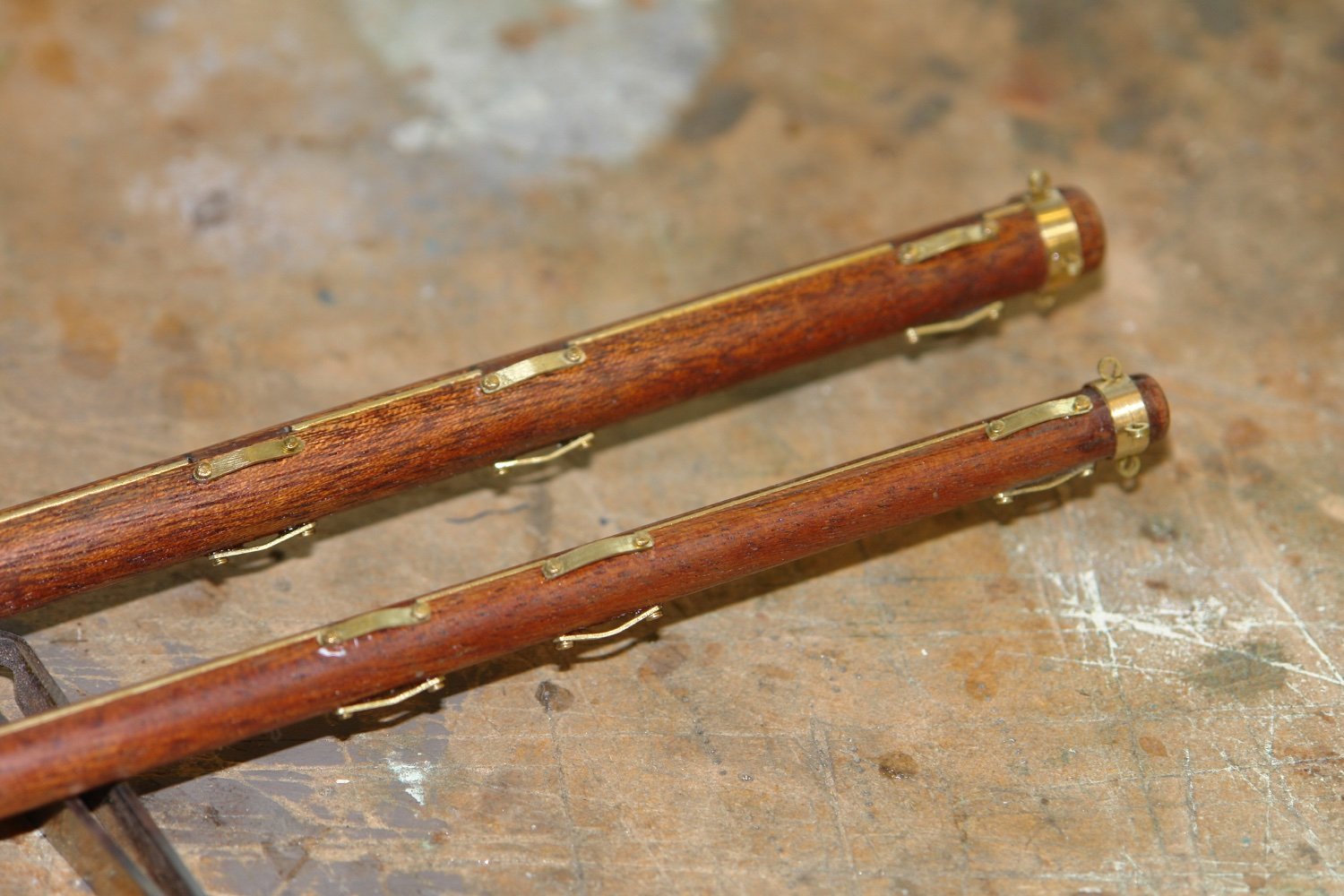
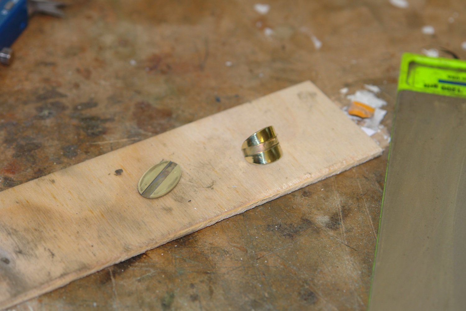
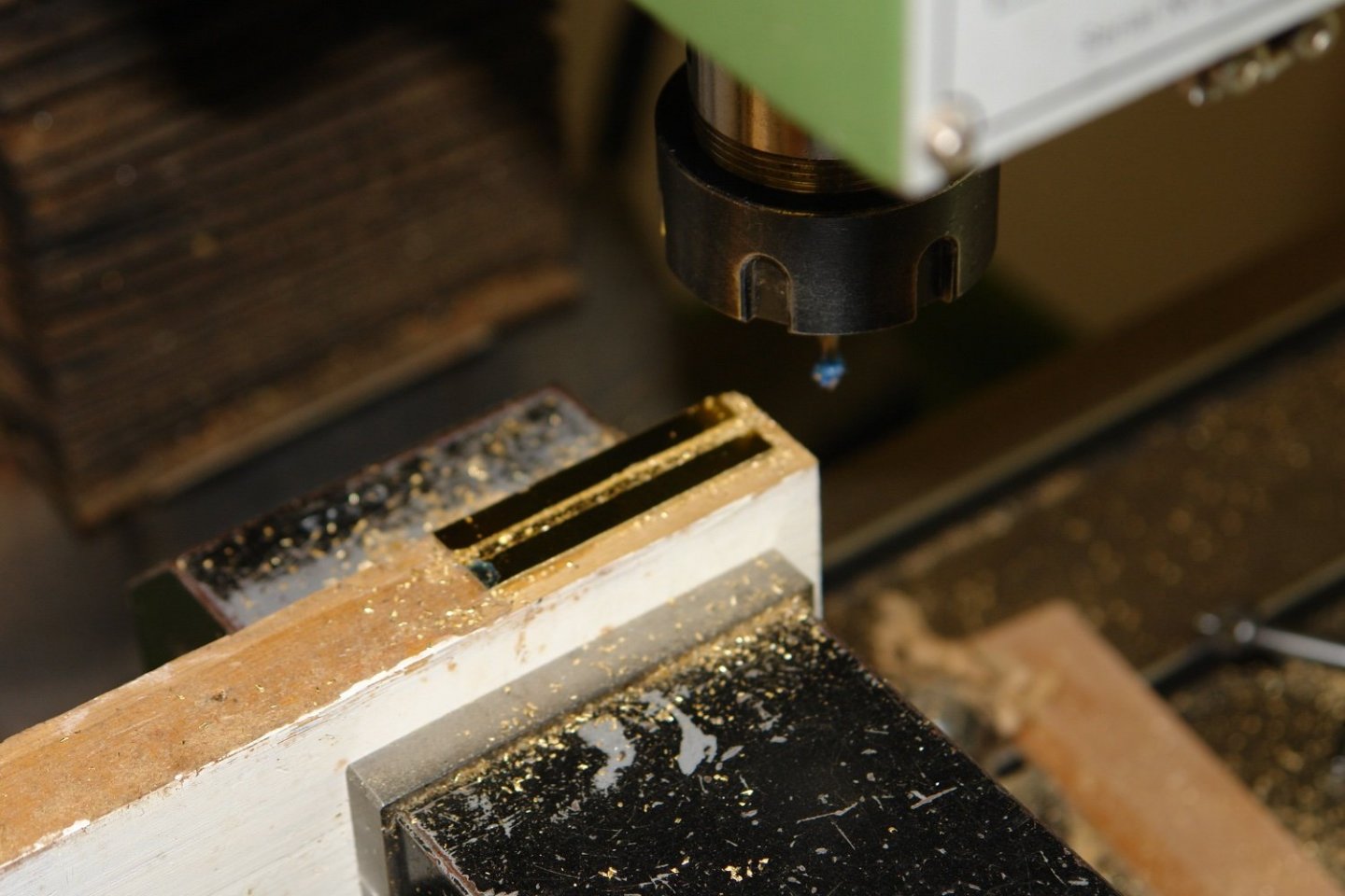
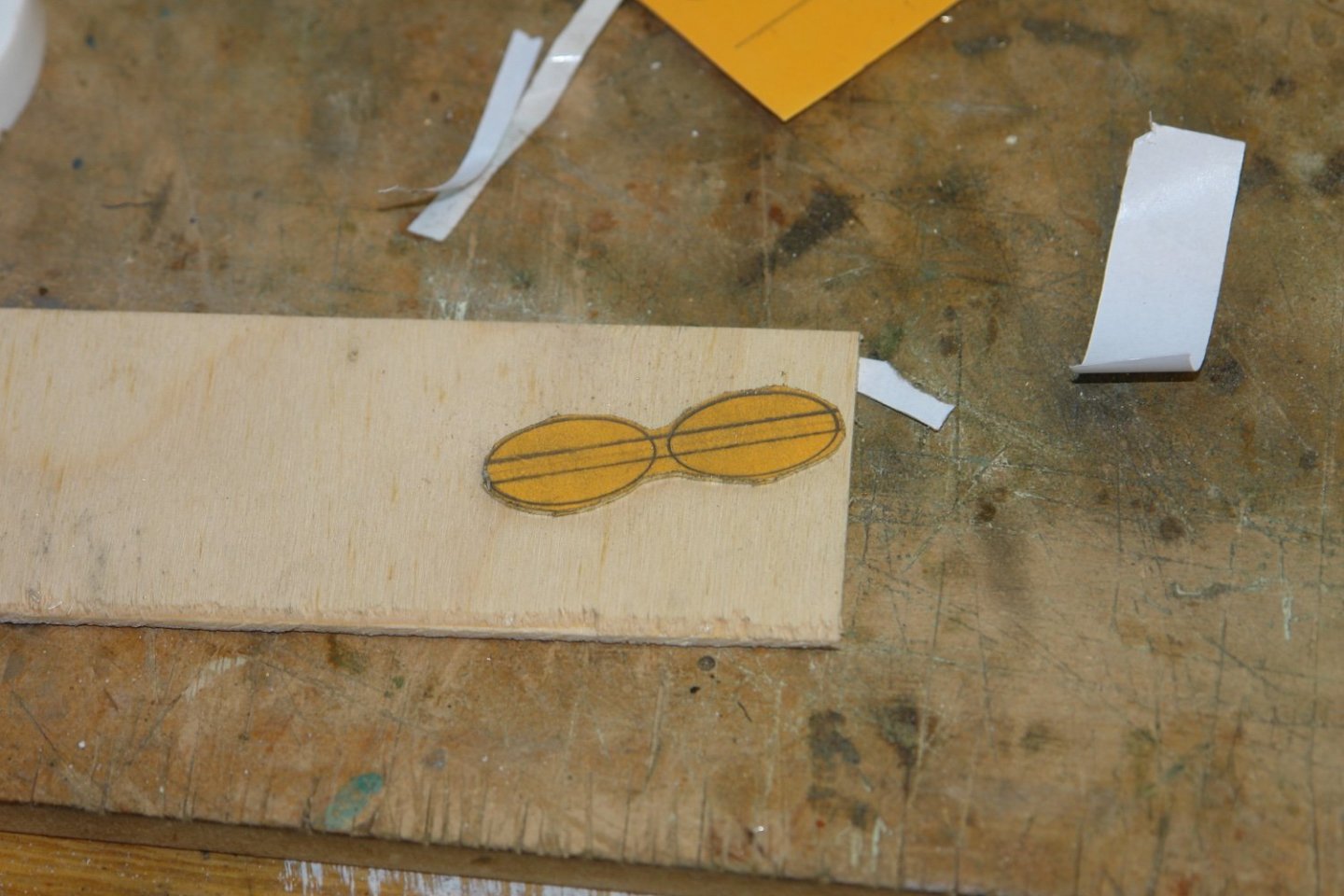
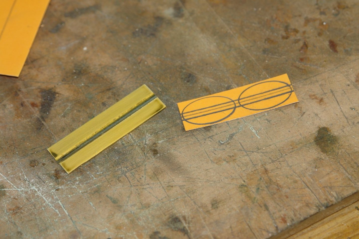
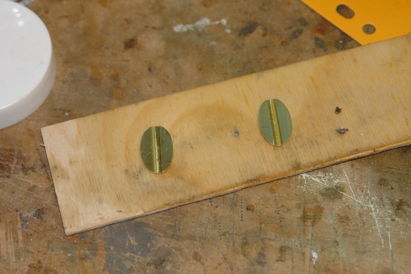
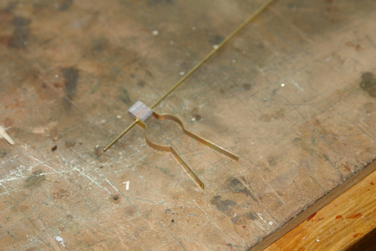
I finished off the other ends of the gaffs before moving on to the saddles. I started the saddle with a strip of 1/2" wide x .040" thick brass. This was milled along its length to a depth of .020" I marked out the ovals for the saddle on a piece of card and then attached it to the brass strip with double sided tape. I then cut out the ovals with a jewellers saw before finishing with a file. I then annealed the brass and bent the ovals around scrap lengths of steel bar of the same diameter as the masts. I then made the attachment brackets for the gaff out of strips of .020" brass. These were bent to the correct radius with the ends turned out to form the hinge brackets. The piece of aluminium is a spacer to get the brackets correctly positioned. The brackets were then soft soldered to the saddle. The stirrup for the gaff lift was then made. A piece of 3/32" tube was part turned to mark the cutting locations. Holes were then drilled and a piece of shaped .040" wire was bent, inserted and soldered. Finally the small bridging piece was soldered to form the eye. The tube was then cut away. The saddles were then mounted on the gaffs.


-
Druxey, Gary, Bill and Jon, Thank you all for your kind comments. It seems amazing that I started this build 3 years ago - how time flies. My hope is that some time this year I will get started on another build. As I get older I find myself rejecting long duration projects!
-
Mark -, preferably steel or brass - for removing excess solder.
-
Great project. I must have seen her while visiting the museum, but don’t recollect. I look forward to seeing her develop.
- 30 replies
-
- 3
-
-

-
- small
- clinker built
- (and 2 more)
-
So now we know, it was you who was responsible for initiating Chinese world manufacturing dominance.
-
The internet is festooned with small wire brushes for Dremel type drills. My experience is that most of them are rubbish. They either disintegrate or wrap themselves into a tight ball. Can anyone recommend a source of high quality small rotary wire brushes? By small I mean up to 1" diameter.
-
Very nicely done Rob - I must remember that.