

CDR_Ret
-
Posts
548 -
Joined
-
Last visited
Content Type
Profiles
Forums
Gallery
Events
Posts posted by CDR_Ret
-
-
Just bought a used copy of Underhill's book today on Amazon for $32. I skimmed the openlibrary.org copy and it has amazingly detailed diagrams of the rigging and masting details not available in the photos I obtained from DTM/CIW of the Galilee. Since this book emphasizes 19th and 20th century sailing merchants, it will likely be a good source for rigging the model. Sadly, the one diagram that I needed to reference wasn't scanned in the digital copy from the Boston Library.
Terry
-
-
-
Hi all.
Anyone know of an authoritative reference showing late 19th-century merchant pinrail diagrams? It is my understanding that belaying pin arrangements were fairly standardized by ship-type throughout most of the world, or at least within a nation's fleet, so that crew could be hired in nearly any port and would be able to serve with little additional training.
I am looking specifically for the pinrail layout typical of a late-19th century, West-Coast, brigantine merchant of medium size.
Any assistance will be appreciated.
Terry Egolf
Colorado Springs, CO, USA
-
-
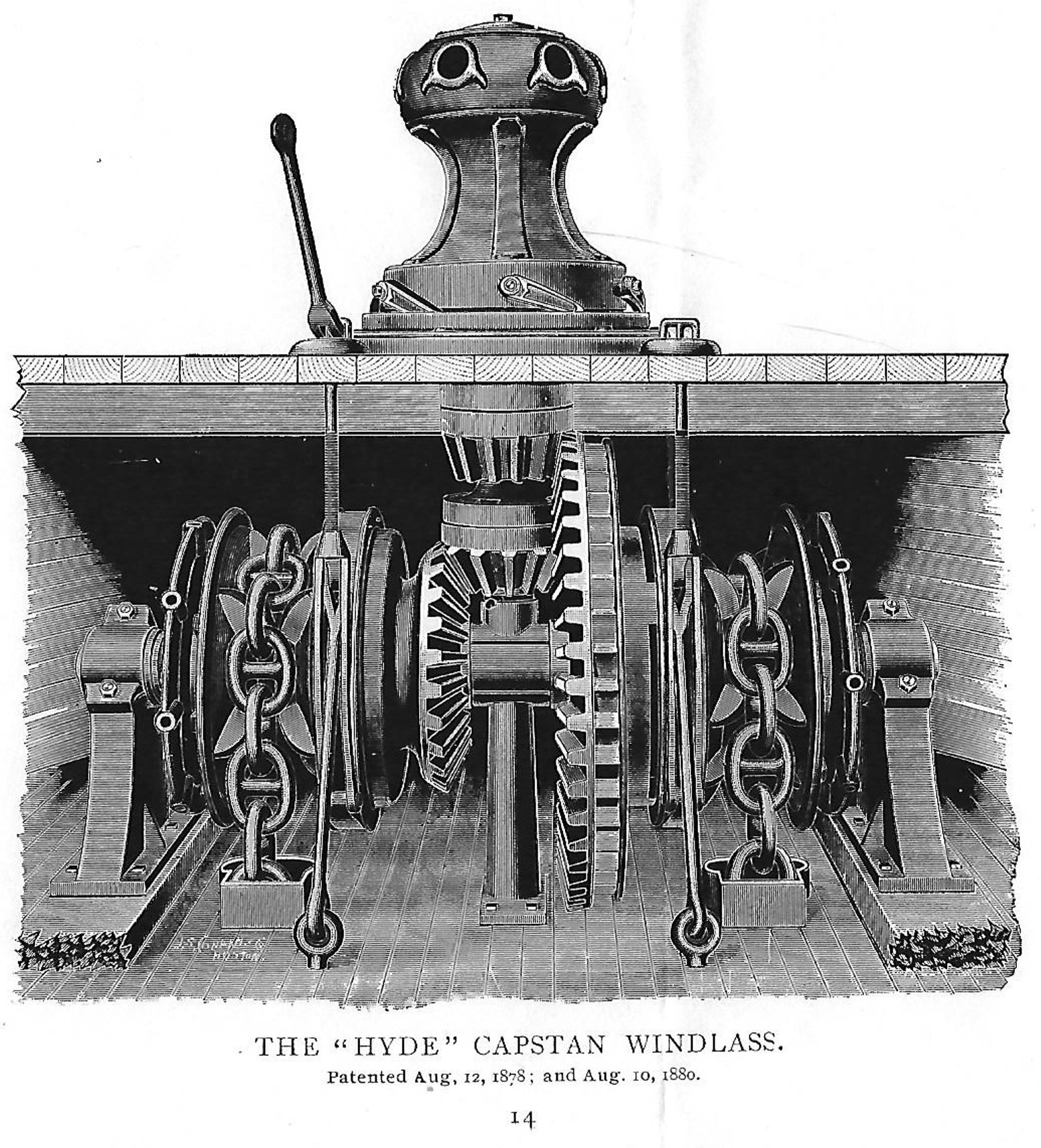
This past weekend, I received a packet from the Maine Maritime Museum*. It contained several scanned pages from a 1902 Hyde Windlass Company (HWC) catalog that related to their manual capstan and windlass machinery. Since the patents listed in the figure were several decades prior to the publication date, the design spans the time the Galilee was built, and is likely representative of the type she carried.
This is the scanned engraving of the machinery from the catalog.
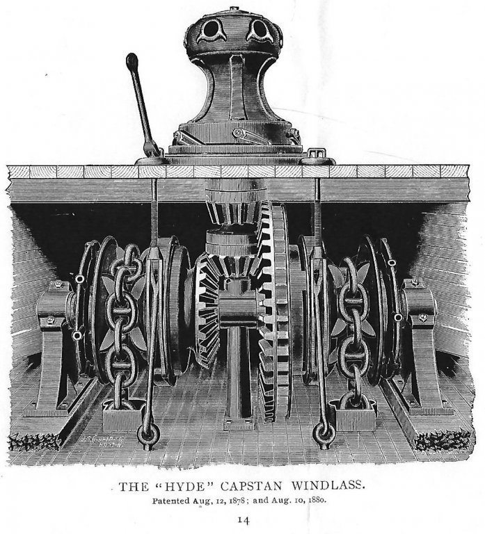
Compare this design with the image in the previous post. The wildcat brake actuators consist of forked lever rods that engage the band brakes from the forecastle deck, rather than screw actuators mounted on the main deck as I drew them.
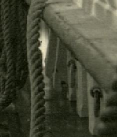
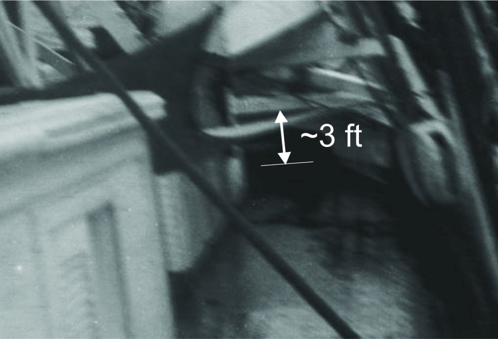
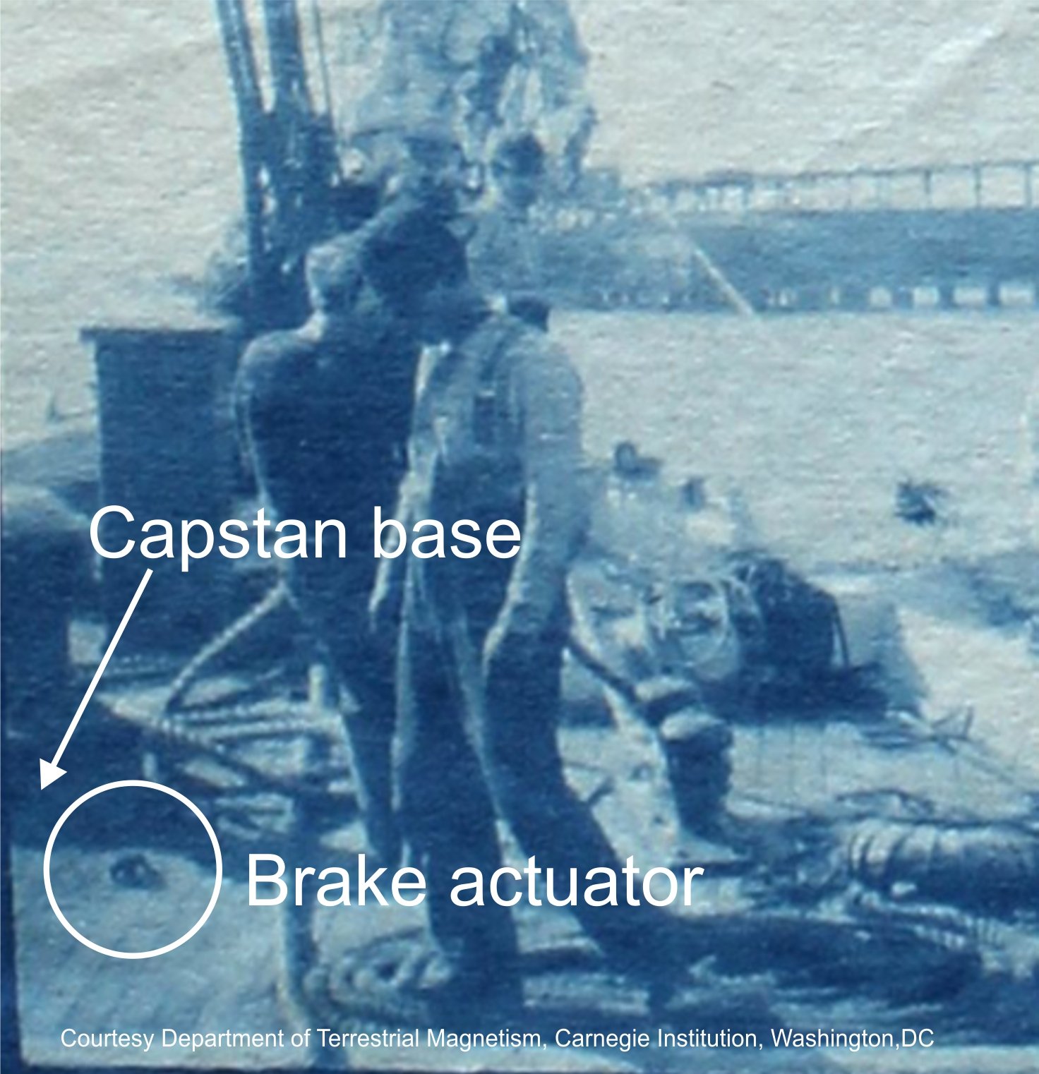
It turns out that Galilee did indeed have this type of brake control, as indicated in the following photograph, which was taken in 1905 during her outfitting as a magnetic research vessel. I also discovered from this photo that the capstan was mounted on a base about 8–10 inches high. This is referred to in HWC catalog, so I will need to include that detail in the final plans.

So I am now much more confident that I have identified at least a plausible anchor handling gear for this vessel, and can now move on to other deck furniture.
Terry
*Maine Maritime Museum contact information:
Anne Witty, Chief Curator
Maine Maritime Museum
243 Washington Street
Bath, Maine (ME) 04530
Tel: 207-443-1316, ext. 328
Email: witty@maritimeme.org
-
FYI, Shapeways, the 3D printing company, shared an email today that lists five popular (and free) 3D drafting programs that you can use to create models suitable for 3D printing.
They are:
TinkerCAD
Sketchup (good for creating deck furniture, rigging components, etc. Frames and planking are more difficult)
Sculptris (a free version of Zbrush)
3D Slash (not recommended for ship modeling; too blocky)
Ultimaker's Cura (checks models before 3D printing)
And there are always Blender and DELFTship. These are also free, but their learning curves are pretty steep.
Terry
-
Hi Matle,
The items you labeled "1" and "2" in your original post are probably chesstrees. These are vertical timbers of wood fastened to the inside surfaces of bulwarks (or frames) for the purpose of redirecting the tacks and sheets of the lower courses for belaying. Their designs appear to be quite variable. Some have sheaves incorporated into their upper ends. Others seem to be more like vertically-oriented, one-ended cleats, with the "thumb" of lower end used to change the direction of the line. They are described in The Art of Rigging by George Biddlecombe and in The Ship Model's Assistant by Charles G. Davis, as well as on-line. Davis's book includes a diagram of a typical chesstree found in a 17th-century sailing vessel.
Matthew Turner's Galilee (also a late 19th century, West Coast merchant) had four chesstress on both bulwarks. The Smithsonian plans identify them and show a cross section, regrettably not very clearly.
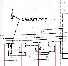
The photo below shows a pair of chesstrees on Galilee's port bulwark.
Hope this helps answer your question.
Terry
-
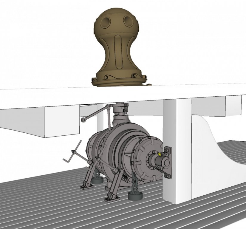
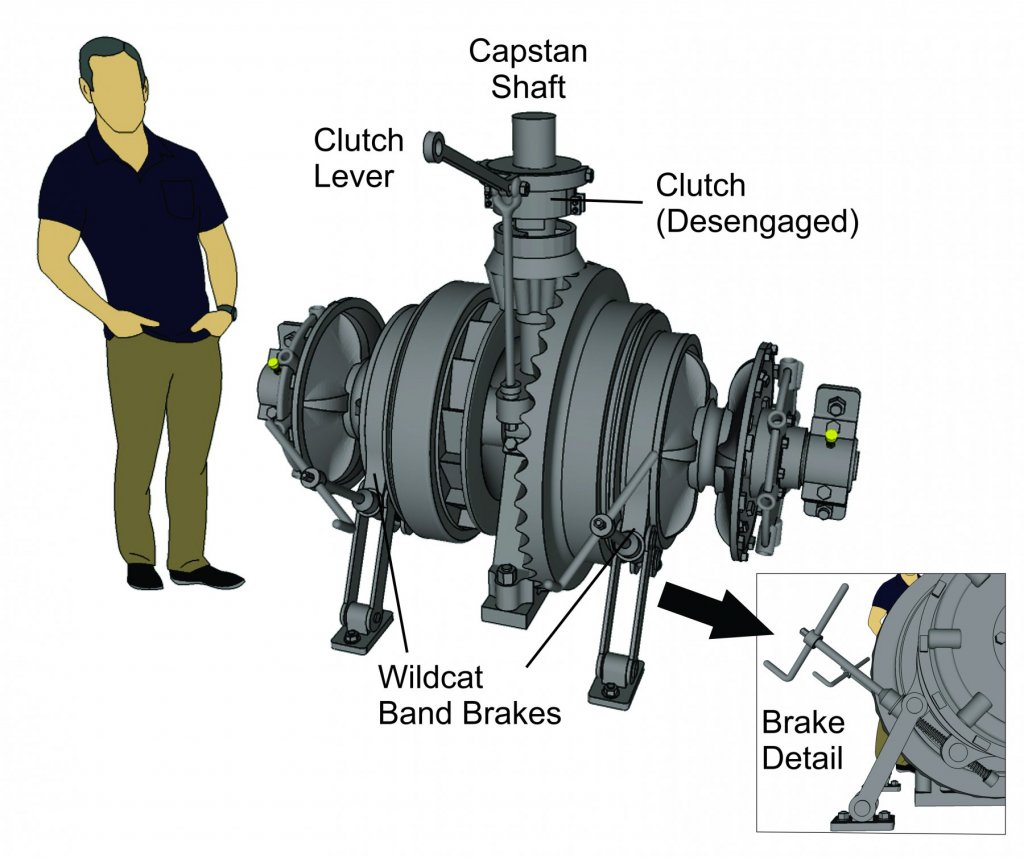
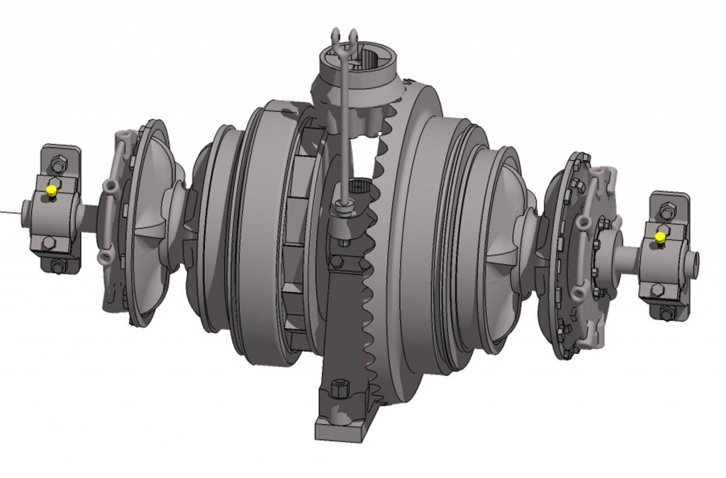
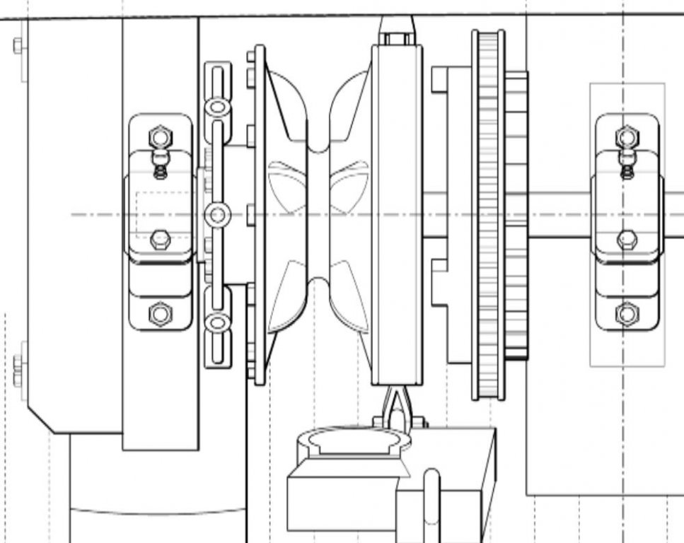
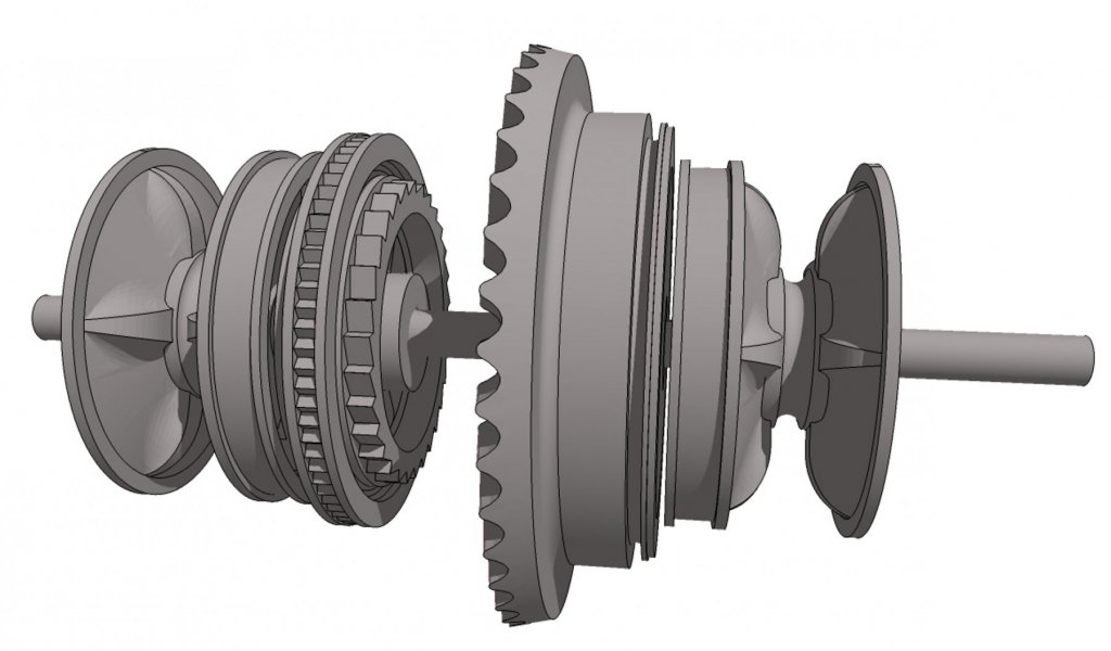
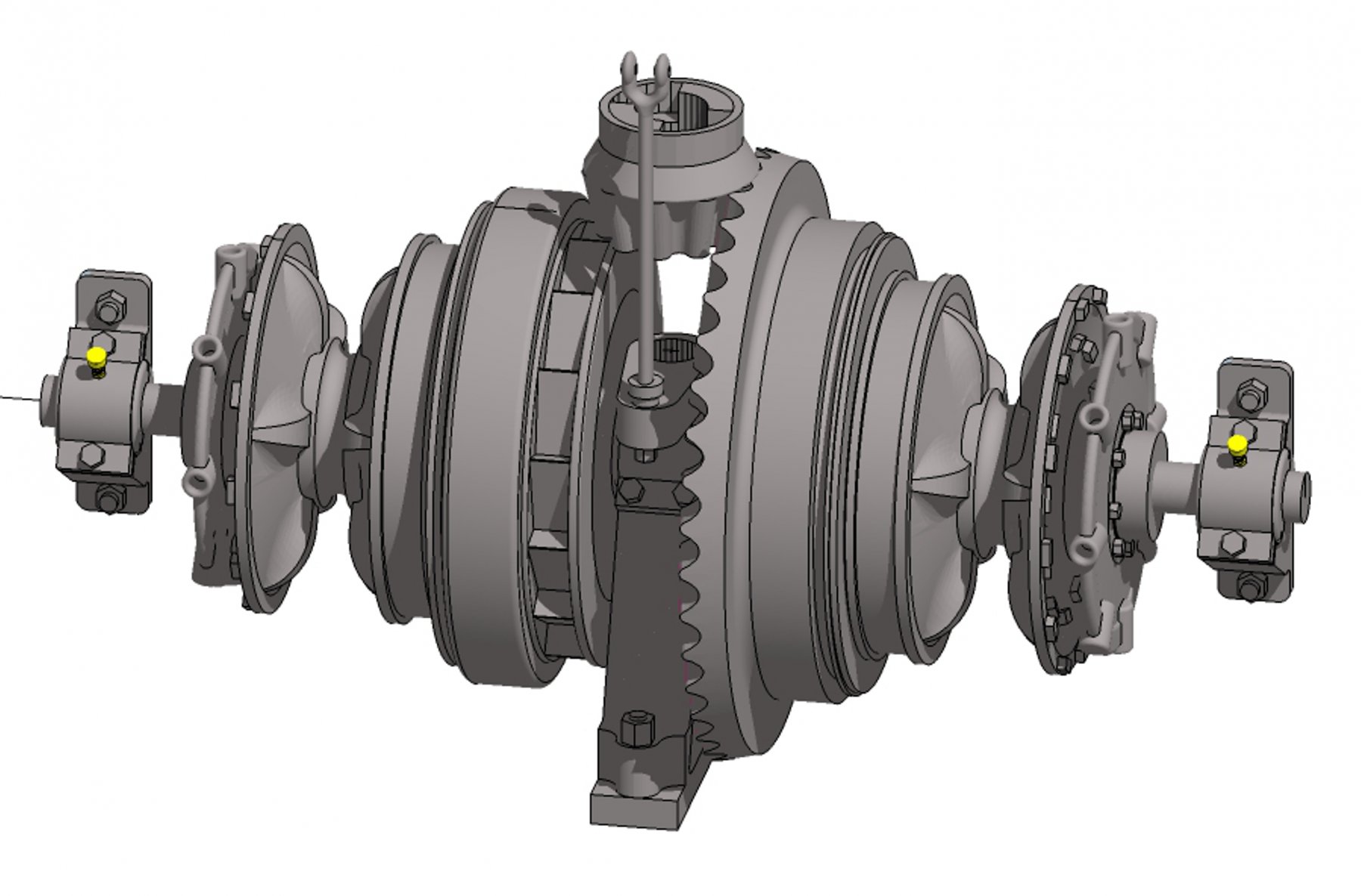
Aaannd .... here is the final image in this topic showing the capstan and windlass in the context of the forecastle space. Based on my reconstruction of the Galilee plans, there will be about 39 inches of room between decks, so I had to downscale the windlass machinery to fit. I also flipped the clutch actuator so that I could maximize the size of the rest of the equipment.
The image seems tilted because the equipment rests on the extreme forward sweep of the deck sheer. There is a 4-degree slope at this point on the deck. Anchor chain comes up from the chain locker through pipes in the deck immediately below the wildcats and lead forward through chain stoppers (not shown) to the hawse pipes in the bow.
-
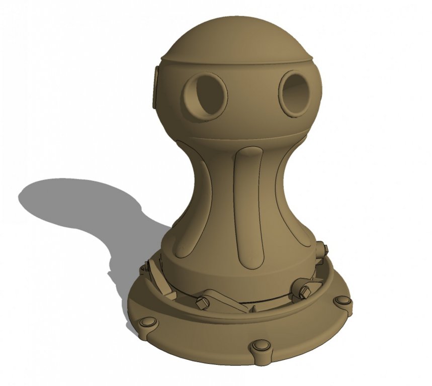
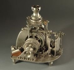
Here is my reconstruction of the Galilee's capstan, based on the DTM photo of the upper 2/3 of the actual capstan, with reference to a 1915 Hyde Windlass Company catalog and a random photo of another similar capstan I found on a photo sharing site.
While Sketchup can support creating such models, there is a lot of fiddly mesh editing that is required, involving many hundreds (thousands?) of faces and edges. To minimize this cleanup, I created a clean version of a one-sixth sector of the capstan, then did a rotational copy five times to duplicate the sector, resulting in a complete model.
The next step will be to marry the capstan to the windlass, then place them in context with the decks and structural members as they would have been on the ship itself. This will help me work out the details for framing in the vicinity of this machinery.
Terry
-
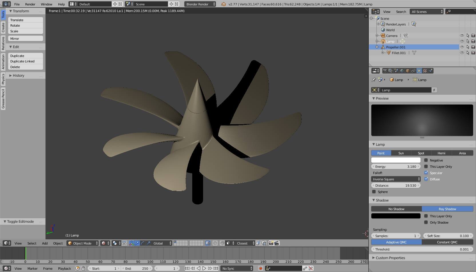
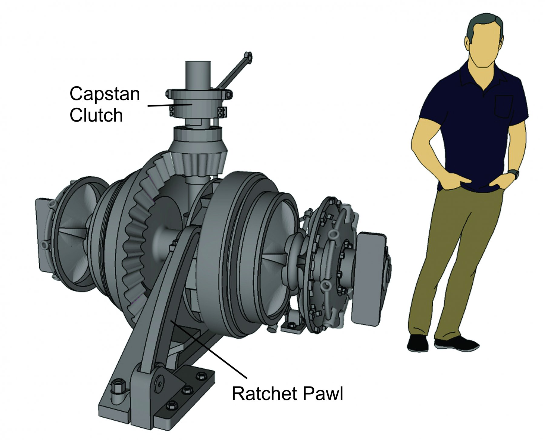
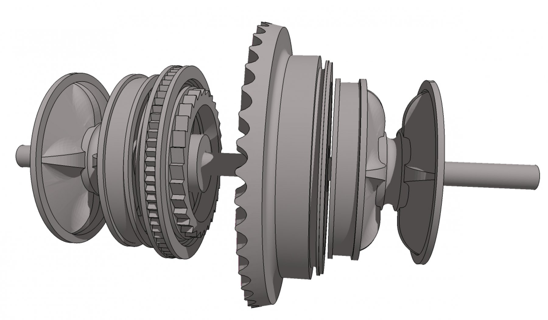
I finally finished drafting up my reconstruction of a Hyde windlass that could have been installed in Galilee. It uses components from Hyde and windlasses found in ships contemporary with Galilee that served on the West Coast of the USA. Since the prototypes were found on ships larger than Galilee, I will likely have to scale this down to a size that will fit in her forecastle. I am hoping to develop a model of her capstan, then show the combined capstan/windlass machinery as it might have been installed in the ship, with appropriate timbers and decking. Oh yeah, and that band brake operator contains a true 2-inch trapezoidal ACME thread developed from ANSI references. Quite fun to make!
So far, most of the major components have been separately built in Sketchup Make 2017, and are manifold, which means they could be 3D printed if desired.
Terry

-
-
Update on my reconstruction of Galilee's capstan. I am three weeks out from a repair of a 25-year-old hernia repair, so I've been recuperating rather than sitting at a computer... (for you older guys, my surgeon informed me that redos of inguinal hernia repairs in men are quite common. The joys of aging!)
These images show progress and corrections from the previous post. I have most of the key components modeled in Sketchup Make 2017. The only things left for the windlass are the controls (ratchet pawl, wildcat band brakes, and capstan clutch lever).
I realized after the fact that the double pawl wheel shown previously was applicable to the lever-style capstan I was using as a reference. It has been replaced with just the windlass pawl ratchet wheel.
Please feel free to ask any questions.
Terry

-
Note that Sketchup's default image import resolution is pretty low. To maximize the line sharpness of imported images, which is essential for tracing plan lines, do the following (applicable to Windows systems):
1. Navigate to Sketchup Preferences. (Window|Preferences)
2. Select OpenGL
3. Check Use maximum texture size.
4. Click OK.
I included a screenshot of a windlass plan in the default and max resolutions so you can see the difference. These are rendered using a high-end graphics processor, so you can see that it is Sketchup that is affecting the appearance. Large images at maximum texture sizes will slow down the editing process without a good graphics card. See the Warning screenshot.

- thibaultron and Nirvana
-
 2
2
-
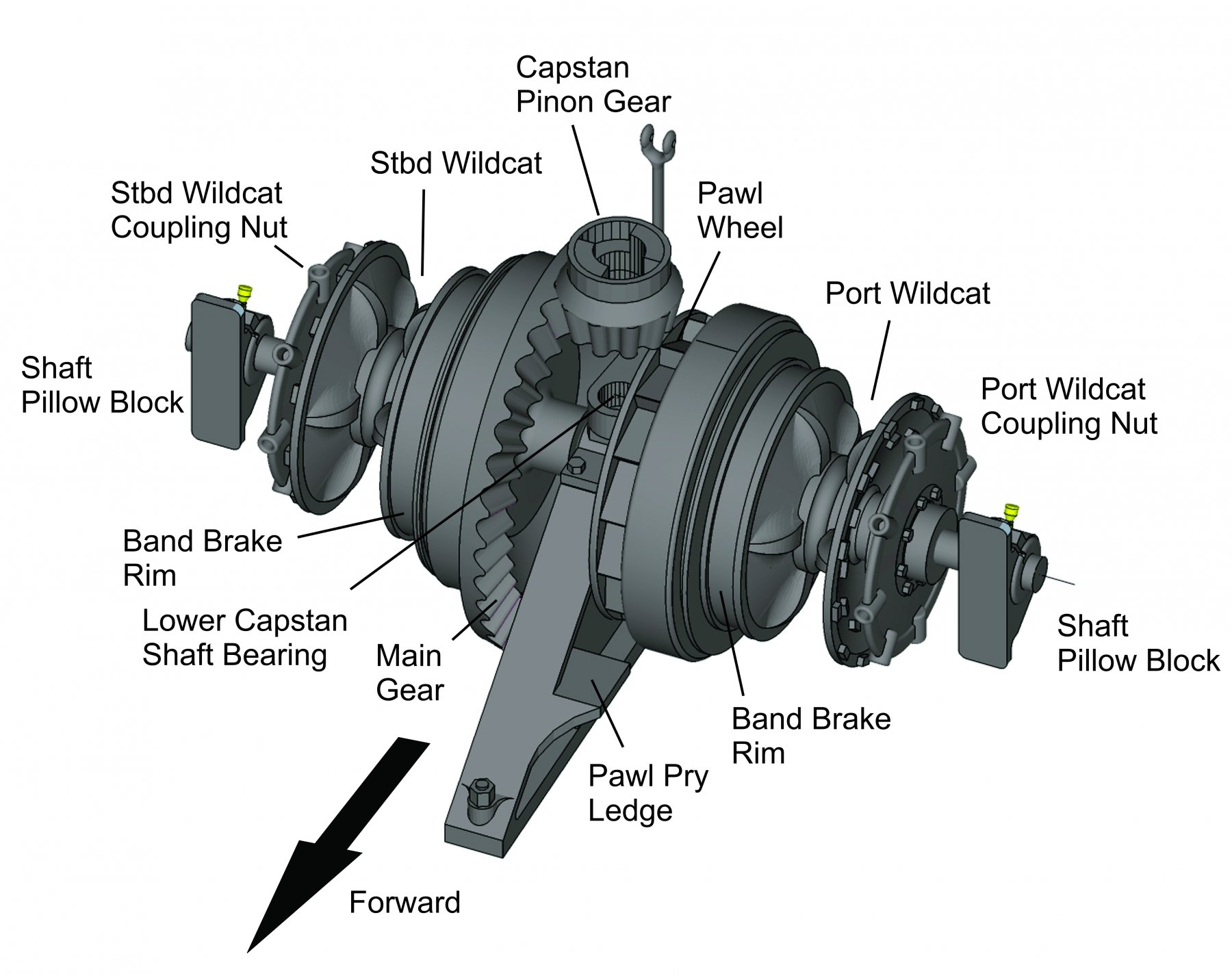
Here is the current status on reconstructing Galilee's windlass using the resources I have available. The diagram is constructed in Sketchup Make 2017 using the basic tool set. This part is probably the hardest to create, with all the curved surfaces in the wildcats and the crown gear. All that remains is creating the operating gear and the mounts to the ship's frames. I suspect that the windlass was mounted to the deck structural timbers, similar to the Lucerne and Thayer, rather than having a separate metal foundation like the Balclutha.
I'm hoping that this will be 3D-printable, but the level of detail at the anticipated scale of the model will probably be lost or not printable.
Terry
- mtaylor, druxey, John Allen and 2 others
-
5
-
Thanks Roger—good call. Sadly, the Thayer's windlass is actuated by a rocker-type mechanism. It has a standard capstan forward on the forecastle, but there isn't any indication it is linked to the windlass.
However, it is a Hyde windlass, so I should probably be able to pattern the wildcats and related hardware based on these drawings. It seems this type of windlass was bolted to a pair of bitts. However, Galilee had only one large
bollardsamson post located centerline and forward of the capstan. Evidently, the windlass supports were incorporated into the forecastle deck framing.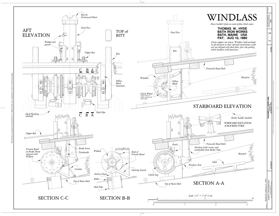

-
Took a few hours today to do a detailed search of the Web on this topic. The only things I came up with were the following.
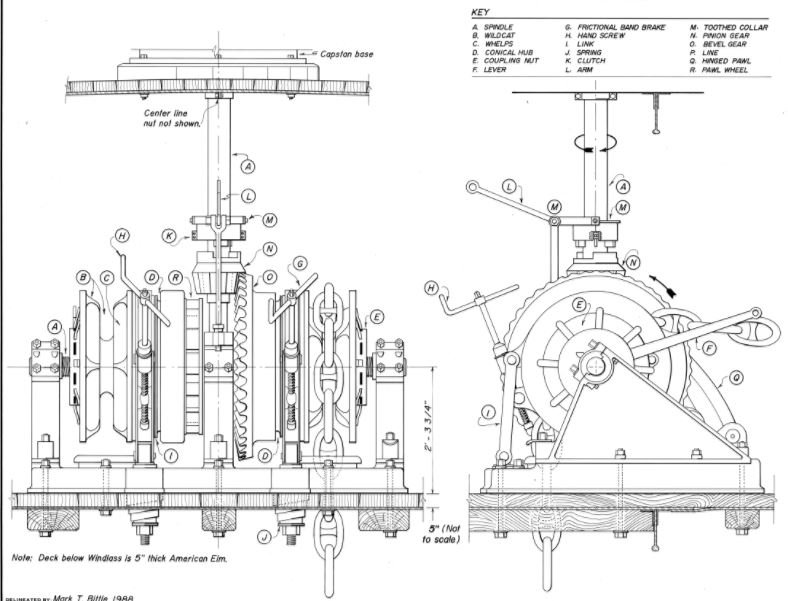
Balclutha, which is one of the premier museum vessels held by the San Francisco Maritime National Historical Park, is extremely well documented through the National Park Service HAER program. Several of the scale drawings in that program include diagrams of the anchor windlass, which is shown below. Though the Balclutha is much larger than Galilee, she is almost contemporary to the brigantine. The following diagram shows Balclutha's hand-powered anchor windlass.
The photo below that I found on Pinterest of capstan/windlass of the sunken Lucerne (check out the Wikipedia article) is probably more similar to the one Galilee carried. Since there doesn't seem to be any contemporary diagrams available of a Hyde windlass, I'll have to approximate one when developing the ship's plans.
- Duanelaker, jud, JerseyCity Frankie and 3 others
-
6
-
Bill, thank you for the link to that HWC catalog. It is my impression that, by 1917, Hyde had dropped their manual/hand-operated windlasses for all sorts of powered types, which are described in the catalog. During the transition period (probably around the time this ship was built), steam windlasses still had a capstan for motive power when steam wasn't available for some reason. That is why the capstan is geared into the windlass from a point above the unit, as shown in the brass model I posted above. Still, the book is an excellent reference, which I will definitely save.
Roger, any windlass originally designed for operation by steam won't work for my purposes. Galilee was one of the last of the sail-only brigantines built on the West Coast for merchant service. She originally had a small steam donkey engine amidships for handling cargo and boats, but that was removed during the time my grandfather sailed in her. The crew operated the capstan/windlass by the traditional means—capstan bars and hard work!
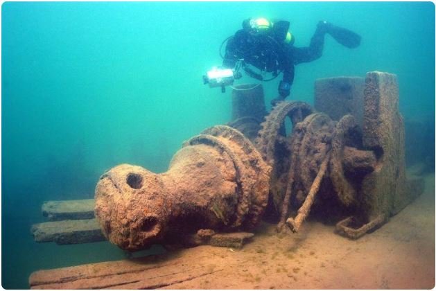
I'm pretty sure the windlass was operated from the capstan above. As the photo below shows, there was no room for the crew to operate the machinery for raising and lowering the anchors between decks.
[Looking forward toward the forecastle on starboard side during heavy weather.]
Photo courtesy of the Department of Terrestrial Magnetism, Carnegie Institution, Washington DC.
Thanks again for your responses and interest.
Terry
-
Hello, All.
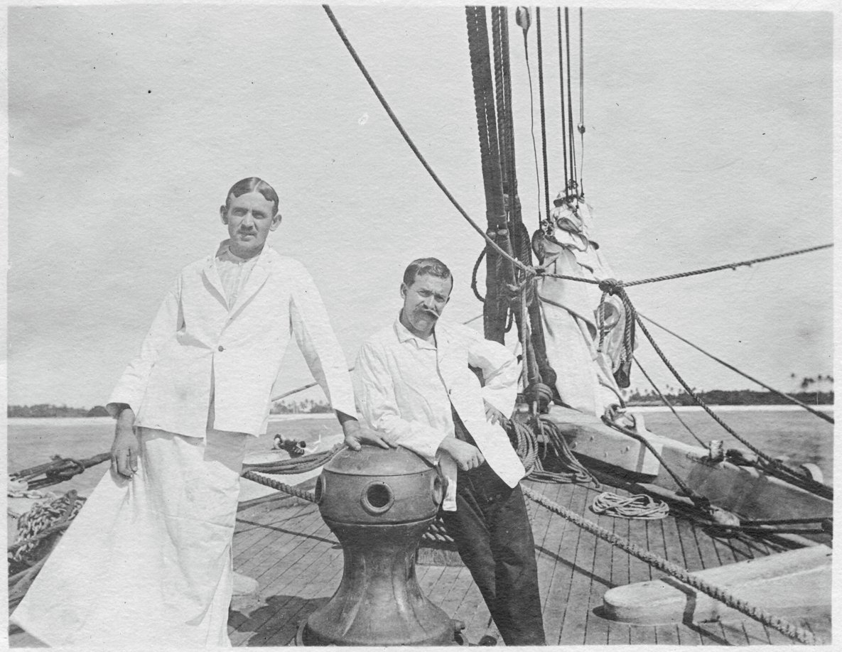
I've been searching for any plans/photos/schematics of a Hyde Windlass Company (HWC) hand capstan and windlass assembly. This would be sized for a 350-ton sailing merchant around 1890. The brigantine Galilee was launched in 1891 in California and seems to have been equipped with a Hyde capstan (see the photo below).

Photo courtesy of the Department of Terrestrial Magnetism, Carnegie Institution, Washington DC (c. 1907)
(The attire of the men is somewhat strange. The research crew's surgeon is on the right and his steward/surgical assistant is dressed for surgery.)
What I really need is some information about the windlass, which was located in the open forecastle under the deck. I would like to render this equipment as accurately as possible, since it will be visible in the finished model.
An entire windlass/capstan assembly has been modeled; its images are available on the Web. However, all that i have been able to find are steam windlasses, like the one shown here.
Galilee's windlass was strictly manual.
I have already contacted the Maine Maritime Museum in Bath, ME. They have some extensive archives pertaining to the HWC (which became the Bath Iron Works Shipyard), but their staff is limited and they haven't been able to find what I need so far.
If any members live in or near Bath and would like to look into this, I would be very grateful.
Terry
- mtaylor and Mirabell61
-
2
-
Floyd (fnkershner),
I would be happy to provide some Sketchup coaching for your project at no charge. I am a retired professional educator and enjoy helping people learn new things. What you want to do utilizes just basic functions of Sketchup. Solid objects created in Sketchup are inherently manifold and 3D-printable unless you break the envelope or introduce extra geometry in an uncontrolled fashion.
Please PM me with your email address if you are interested.
Terry
Colorado Springs, CO
- fnkershner, thibaultron and mtaylor
-
3
-
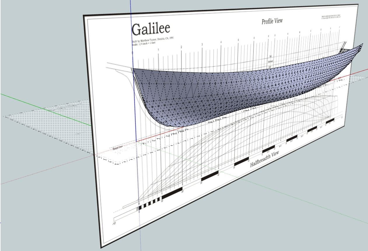
Here is a quick-and-dirty build of Galilee's hull I did in Sketchup a number of years ago using an old set of plans I developed back in 2002. Just wanted to see how it would work to display hull form. Unlike parametric 3D programs and for-the-purpose naval architectural software (e.g., DELFTShip), the result shows distinct polygons when you display hidden lines. It is also a lot of work creating the intersections at stations and waterlines.
Terry

- Nirvana, Mike Y and thibaultron
-
3
-
Here is the instructional PDF for creating sockets in 3D objects.
Please let me know if there is anything that is unclear, and I will try to explain it. A real power-user of Sketchup may be able to come up with a quicker method. I've been using Sketchup almost as long as it has been around, and I'm afraid I've become entrenched with some habits picked up years ago.
Terry
- Mike Y, Nirvana and thibaultron
-
3
-
Sailor1–0,
How familiar are you with the Intersection feature of Sketchup?
You might want to try creating models of the wheel hub and spokes, individually grouping each element and arranging them as in the final object. (Save a copy of a spoke for later.) Then explode the hub and intersect the spokes with it to define the spoke cutouts in the hub. Regroup the hub, then explode the spokes. Intersect the hub with the spokes to define the spoke socket walls inside the hub. Delete all of the spoke components except for the parts that lie inside the hub. Explode the hub and delete the surface areas inside the spoke sockets. If the work is done carefully, the hub now is solid volume with the spoke sockets arranged where they need to be. If needed, recreate the spokes from the copy and insert them into the hub.
The process is somewhat complicated but straightforward. I can provide a PDF with images of the key steps if that will help visualize the process.
Terry
-
Thanks for the comments, guys.
At the time the photos in post #1 were taken, the vessel's charter did not include entry into icebound waters, so no protection against ice floes was needed.
The photos themselves don't show enough details of the hull covering to draw any firm conclusions. However, the photo of the Pitcairn in #8 shows the distinctive rectangular blotchy appearance associated with copper plating. The plates themselves are of about the same vertical dimensions as the linear marks in the #1 photos, so I am going copper plates. The darkness of the hull in the old B&W photos is likely due to the color response of the film in use at that time, which wasn't sensitive to the red end of the spectrum.


Professional help needed
in Nautical/Naval History
Posted
Hi Chief.
Don't suppose you have any photos of this situation?
Changing the load line of a ship isn't a trivial thing. Either the ship had reserve cargo capacity built in or someone is playing with the stability tables. It would seem that seaworthiness certifications and insurance companies would have something to say about such an act.
From my limited familiarity with marine physics, I would think that the main adverse effects to raising the load line would be reducing reserve buoyancy and some effect on the righting moment (the actual effect on stability might either reduce it or increase it, depending on a number of factors).
As for the weld issues, I'm having a hard time visualizing the problem. Are there gaps (broken welds) at regular intervals along the keel, that would indicate some relationship to deep frame locations? Does this condition basically flood the keel structure with seawater?
Overall, welding plates between the buckles seems to be a band-aid approach to the problem. There is obviously some serious structural issues at work.
Terry