

CDR_Ret
-
Posts
548 -
Joined
-
Last visited
Content Type
Profiles
Forums
Gallery
Events
Posts posted by CDR_Ret
-
-
-
Keith, are you a lawyer by any chance?
- Rik Thistle, lmagna and mtaylor
-
 3
3
-
Just don't call a ship a boat, unless it's a submarine!
I don't know how many articles I read over the past several weeks about the "boat" stuck in the Suez Canal! 🤨
-
Continuing to work from aft to forward, today is the towed sonar array tube and faring.
The Sturgeons were already being constructed when the US submarine force received their towed arrays. These sonars were towed a long distance behind the ships to remove the receivers from the vicinity of the largest sound source in the area—the towing submarine itself. So the early towed array systems were add-ons for the Permit-, Sturgeon-, and the Los Angeles-classes. (The towed array systems for the Sea Wolfs and Virginias are totally internal.)
The handling gear for the array cable was installed in a forward ballast tank and the sonar array itself was stowed in a long tube that led to the stern planes. The "flushing tube" laid against the hull and was covered by a low fairing topside. The aft end of the tube had to extend far enough aft so that when the ship executed a sharp turn, the array wouldn't be cut off by the prop. (The Soviets solved this problem by putting their array and handling gear in a pod on top of the vertical stabilizer of the rudder.)
The sonar tube was called the "flushing tube" because the array was deployed and retracted by pumping water through it to "flush" the array out and lubricate its retraction.
The most difficult part of modeling this component was the topside flushing tube fairing, which twists in three dimensions as it lies along the hull.
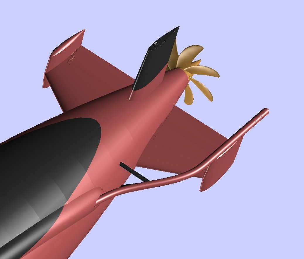
Sturgeon Class Towed Array Flushing Tube and Support
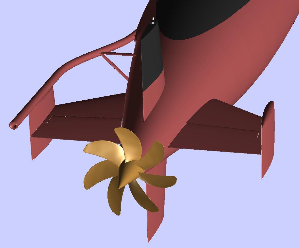
Aft view of the Towed Array Flushing Tube
Towed Array Fairing
Modeled in DELFTship
Terry
-
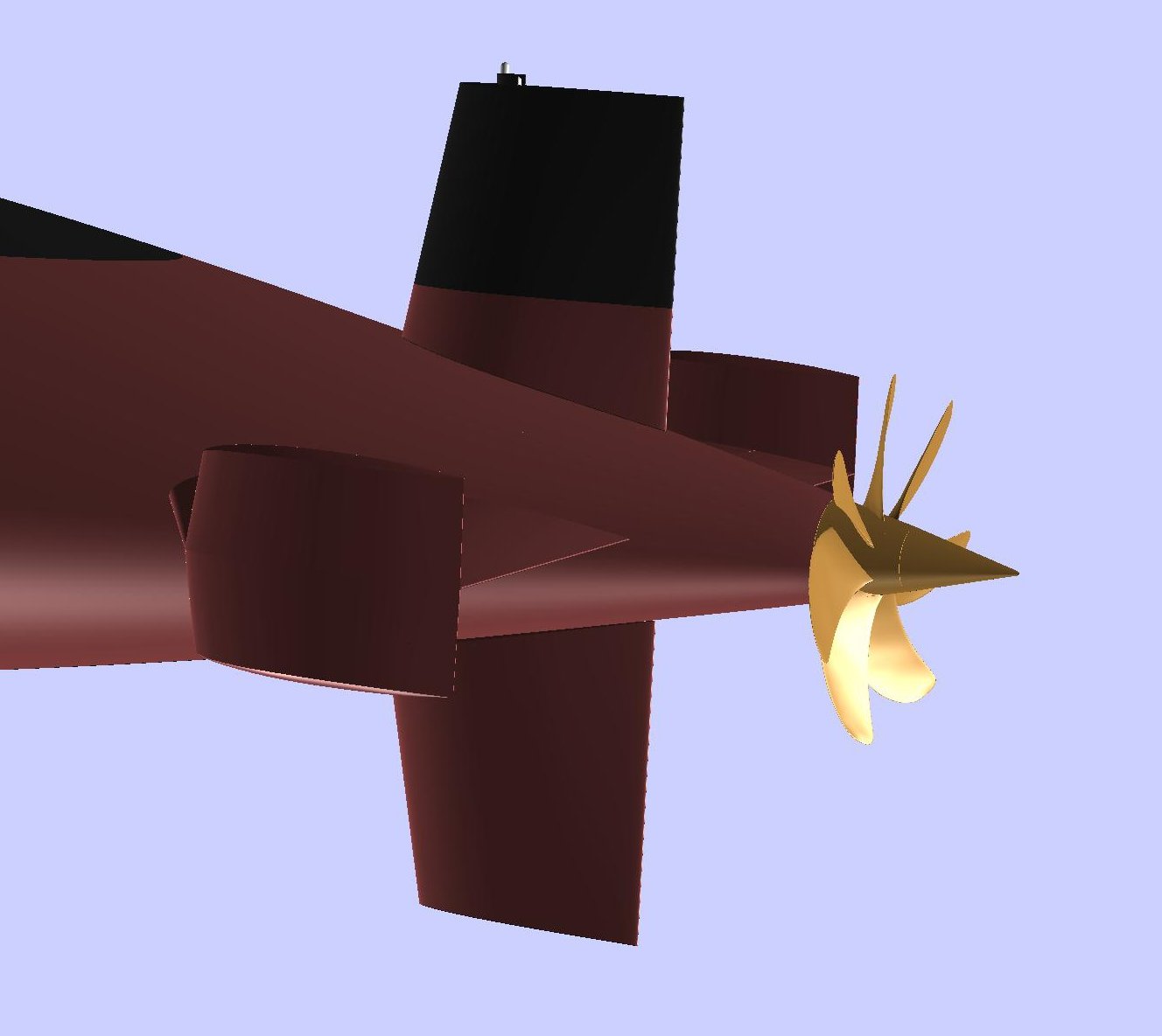
Took a few hours this weekend to build the submarine rudders and the stern light.

The Sturgeon balanced rudders acted together on a single shaft. The lower rudder worked as a standard rudder when the ship was surfaced. Submerged, the upper rudder added twice the turning leverage. Let's just say that these SSNs were pretty nimble when submerged. At a flank bell, you had to hang on during the turn!
Sturgeons had a single, combination stern light housing. The lower enclosure provided the screening needed for the 135-degree stern light used underway. The upper lamp was the 360-degree aft anchor light. Both lamps were in pressure-proof globes rated to the ship's maximum operating depth. The light to be illuminated was selectable from inside the ship.

Terry
-
Yeah, I've heard these stories even back when I was still in the Navy. The circumstances change every time I hear it. The one that was popular back then was that President Clinton had authorized the sale of a poly-axis propeller milling machine to the Chinese even though it was on the strategic items restricted list (or whatever it was called).
-
Rather than continuing to clog up a thread on the features and foils of the DELFTship modeling software with my personal project, I decided to move the relevant posts regarding the project to a separate thread.
If Admins can move the original posts and responses to this thread, that would be appreciated. Otherwise, not a biggie.
The original posts can be found at the following links:
Hull against background plans.
Stern Planes and Control Surfaces.
Follow-on progress will appear here.
Does this qualify for a "build log?" 🤔
Terry
-
Taking a break from editing the final drafts of the transcriptions of my grandfather's diaries.
Added the Sturgeon's stern planes and control surfaces. Started using some of DELFTship's useful tools, like the Mirror tool. This way, you only have to create one-fourth of the complicated curvy surfaces, such as the vertical stabilizers. Then you can mirror the part across the vertical longitudinal plane and the horizontal plane. Only a quarter of the work!
Those vertical slabs really weren't stabilizers. They were originally intended to house the aftermost set of PUFFS (Passive Underwater Fire Control Feasibility System) sonar arrays. That idea fell through for this class, only to be resurrected in a more sophisticated form with later classes of submarines. I think an engineer finally figured out that having a passive sonar array so close to the propeller probably wasn't going to work. Every ship of the class had these housings, though.
Here is a view showing the control surfaces. Several popular hull plans of this submarine class floating around on the Web show the hinge of the planes at an angle to the centerline of the hull. [Edit: 8/6/22
That simply wouldn't work. The planes have to hinge on a line perpendicular to the hull centerline.Rethinking this, since the planes taper from inboard to outboard, the seam between plane and the stabilizer would show a taper. Some day, I might actually take the time to fix this.] There was only a single huge hydraulic bellcrank to rotate them. They acted together, not like aircraft ailerons.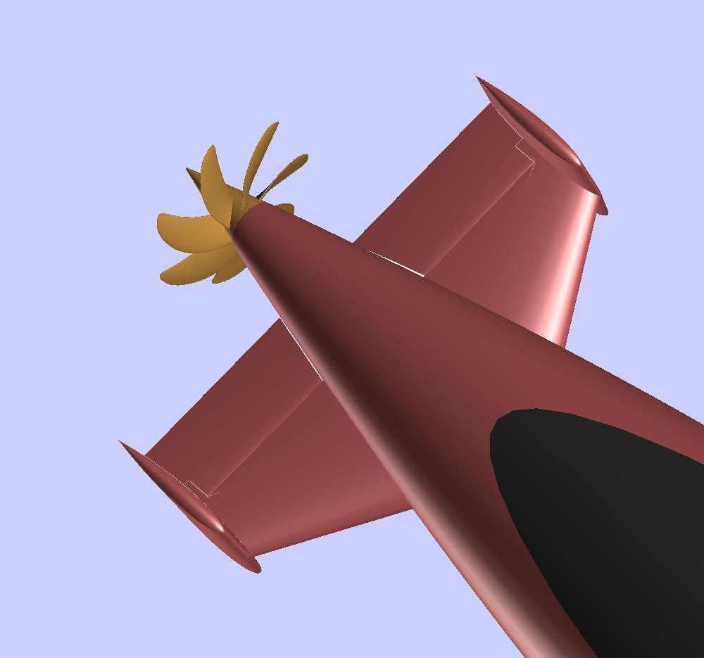
Next will be the upper and lower rudders—when the opportunity presents itself.
Terry
-
Hi Rubkvi.
Nice looking vessel!
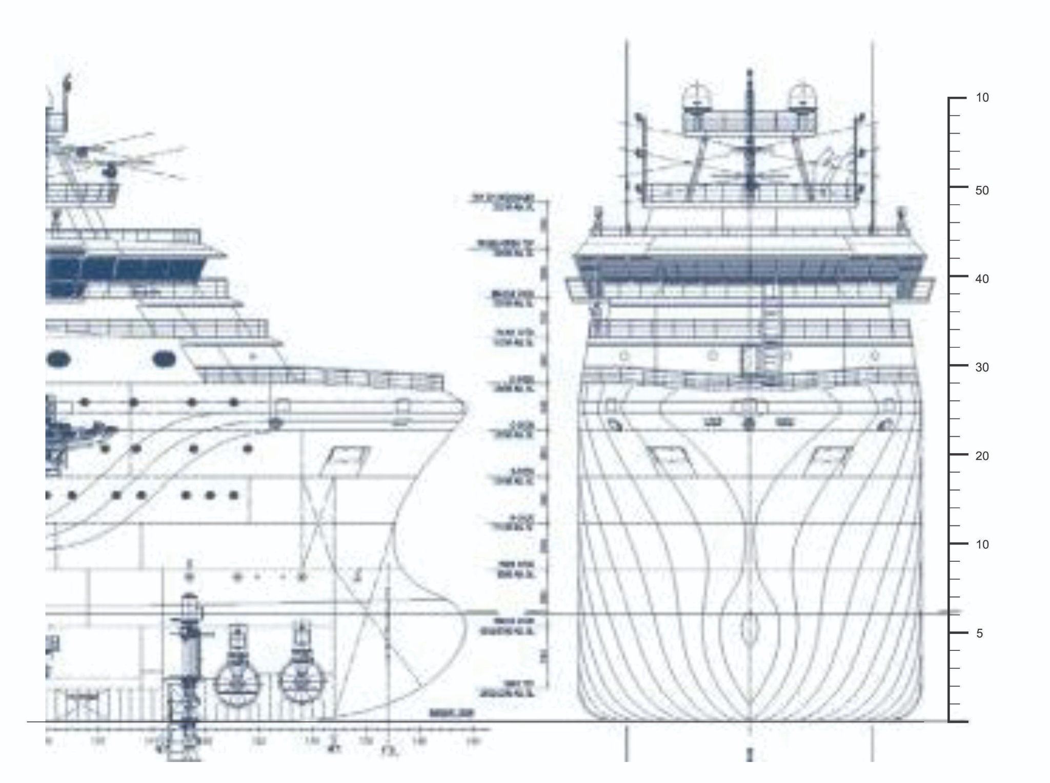
Actually, getting the vertical scale for waterlines is pretty straight forward if you have a good set of plans and 2D software.
First, you take the profile plan and find the dimensions of either its overall length (93.40 m) or its LPP (82.20 m) using the drawing software. This will be a certain number of inches/centimeters. (I noted that the numbers along the keel appear to be frame numbers, not length, nor are they station lines.)
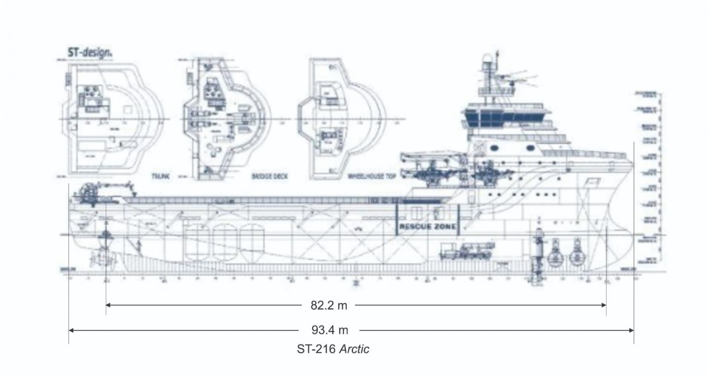
Then you divide the drawing length by the hull length to find the scale inches per meter.
Then build a ruler using this scale. Make it long enough to reach at least to the weather deck. Rotate it to the perpendicular and place it on the vessel's baseline. (Again, the horizontal lines in the body plan are decks, not waterlines.)
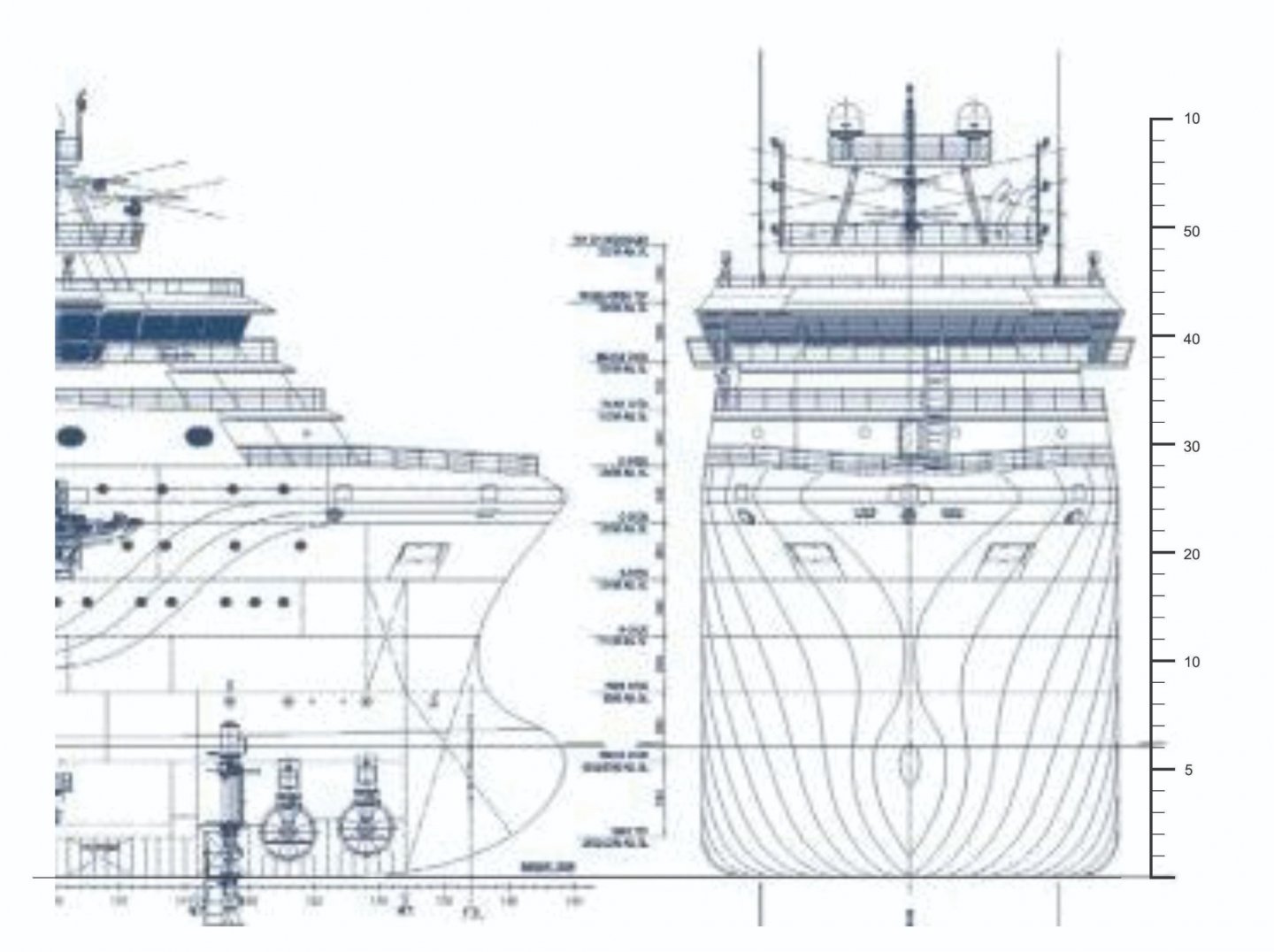
The vertical ruler is in meters.
This should get you to the point where you can create your waterlines for planning.
The station lines will be more difficult. There are 12 station lines visible in the forward view (counting the body plan outline). Figuring that the lower hull's maximum beam (at the tank tops) is about 49 m from the bow, that works out to about 4 m between stations (with maybe 1 m of the bow bulb sticking beyond the forwardmost station line there). A big problem you will have with these plans is that you have little idea what the hull shape is for the stern aft of maximum beam (and there is no aft view of the body plan). Unless you have additional plans and/or photos of the stern area in drydock, this will be difficult to replicate.
Hope this helps.
Terry
-
Great stuff, Kiyoo!
DELFTship exports curves in the DXF format and, as you said, the curves become polylines. The number of line segments depends on the precision level used in the program. I use CorelDraw for the 2D part. It has a feature to convert the corner nodes to smooth nodes, like Bezier curves. The downside is that there are a gazillion nodes, which interferes with creating smooth, fair curves.
So far, I'm with you!
Terry
-
Kiyoo,
As others have said, DELFTship's usefulness to the ship modeler (besides being free) is visualizing the 3D hull, then converting that shape to 2D patterns in a 2D software similar to the process you have described above.
I don't want to highjack your interesting topic with the details of that process here.
What I would like to understand, from simple curiosity, is the process of converting a 2D vector drawing to a laser-cutting pattern. Is that conversion done in the laser control software, or do you have to make the cutting beam allowance in the 2D pattern beforehand? Looking forward to seeing how one does that.
Terry
-
22 minutes ago, CPDDET said:
But what does "R+S" refer to?
There are many here who have a much more detailed understanding if this concept from a historical perspective. But it simply means the combined width of a frame (room) and the distance between frames (space).
So room and space (R + S) is the total distance from, say, the forward surface of a frame to the forward surface of the next frame. The way I understand it, the concept is meaningful only if the frames are set square, have the same sided dimensions, and are equally spaced. But I could be mistaken....
Terry
-
May I suggest that the best way to avoid cumulative errors is to measure each frame's position from the same reference point?
I had the very same issue with my Galilee plans. 16-inch double-frame room, and 12-inch space. 58 frames.
I used a spreadsheet (Excel) and created a formula to calculate the positions of the aft, middle and forward faces of each double frame referenced from the aft-most frame. Each of these positions are 28 inches farther forward along the hull in relation to the previous frame's. The results can be accurately calculated to whatever precision you choose, and in whatever units you need (including fractions, if desired).
After the spreadsheet is filled in. You can use a long precision ruler to accurately mark your frame positions.
Hope this helps.
Terry
-
On 2/25/2021 at 12:49 PM, Rubkvi said:
What CAD software do you recommend for 3d modeling ship hull. And do you know some good tutoriols for that?
I have attempted 3D hull modeling in Trimble's Sketchup. Several members have attempted using the open-source Blender as well as Fusion 360. You can read about their projects here in this CAD and 3D Modelling/Drafting Plans with Software forum. My preference has been DELFTship Free, a for-the-purpose naval architecture program that offers a free version for modelers and backyard boat builders. The company offers a manual that would be good to go through before getting too far into using the program. While the user interface is improving, the actual work in the program can be difficult to pick up until you get to know it or have some guidance. However, that is even more true for the other programs I mentioned. Only DELFTship is configured for ship modeling. It also has the ability of exporting files to an STL format, which you will need for 3D printing.
As far as tutorials go, there are some videos available on the Web. Several of our members, including myself, have posted limited tutorials here on MSW. Just search for "DELFTship" in the Search Field and check them out.
I highly recommend downloading my Background Images Guide that I posted in the New Version of DELFTship thread here. The company just released a major version update that makes using background images for modeling a lot easier than in previous versions.
DELFTship Free and its manual can be downloaded here.
Please feel free to contact me by PM if you have any questions on getting started.
Terry
-
Hello, Rubkvi, and welcome to MSW!
The short answer to your question is No, there is no shortcut, automatic way accessible to the average ship modeller to convert scanned 2D drawings to a 3D digital model. Essentially, one must import a good-quality set of plans into a 3D CAD program such as FreeCAD, DELFTship, Blender, or one of the others mentioned in the posts in this CAD forum. Then you build the model in the program.
You should read through the topics in this forum to understand why this is the case. Just accurately digitizing scanned prints can be a laborious process, even with the best CAD software.
Feel free to ask about the pros and cons of the various methods. This is a very helpful and knowledgeable community!
Terry
-
Anaxamander49:
The short answer to your question is, the reference length is whatever works best for the plans you are using. If your plans show the perpendiculars, those would be best, since that is what the program references in its viewports ("AP" and "FP"). The numerical hull length is critical mainly for hydrostatics and hydrodynamics calculations the program can perform, which generally aren't of concern for modelers of historical vessels.
The program works best for creating building plans if you are using the moulded surface of the hull, not the outer planked surface. For this reason you wouldn't want to use the overall length of the hull for the model's length. I found that anchoring your plans to the underside of the rail, and the inner rabbet lines along the stem, keel, and sternpost works best for starting the hull form. All the other details can be added later, if desired.
I would recommend you download the free manual (Manual_13_mc0.pdf) from the DELFTship website, if you haven't already done so, and read through the the first three sections (Interface, Settings and Preferences, and Hull Modeling) to become oriented to the software. The manual is adequate for getting started but isn't comprehensive. It describes more what the program does rather than how or why. And it is definitely lacking in processes and pitfalls.
Please feel free to PM me or the others here who have worked with DELFTship if you have any questions.
Terry
-
We don't (er, didn't—it's been nearly 30 years since I retired; perhaps the US Navy is today a more kinder, tolerant culture...) use that particular acronym, but we still considered surface sailors as "skimmer pukes!"
In the early days of submarines, it was a typical career path for surface sailors to transition to the conventional submarine force. For the US Navy today, all our boats are nuclear, and virtually all submarine officers and enlisted must complete the nuclear propulsion training pipeline and/or sub school before ever stepping on board any ship.
This YouTube video is the basic idea on how a multi-axis milling machine does a propeller.
Terry
-
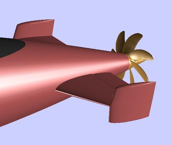
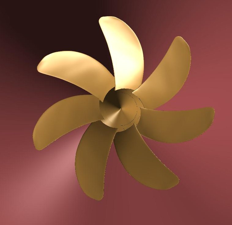
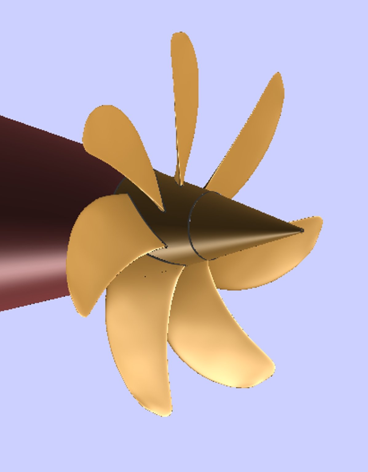
Probably the most difficult aspect of a Cold-War-era submarine model is getting the propeller right. Nearly all nations with advanced submarines came to recognize the acoustic advantages of a seven-bladed, minimum cavitation propeller. The blade shapes are extremely complex, requiring the use of a sophisticated, multi-axis, computerized milling machine.
I have attempted to approximate a submarine propeller in a variety of 3D CAD programs including Sketchup, Blender, and now DELFTship. None of them are easy to use. There is nothing symmetrical about a propeller, except in rotational symmetry. Even then, one has to get the proper blade shape before you can duplicate and rotate the blades to their proper positions. The blades are 51.429 degrees apart (360° ÷ 7). If you are inclined to create a 3D printable model, then you have to cleanly combine the blades with the hub to make the model manifold. That was the hard part.
The following images provide a fairly good approximation of a US nuclear submarine propeller before the advent of the ducted pump-jet types found in the Seawolf- and Virginia-class submarines. This model was created in the latest version of DELFTship. In the process, I discovered several program bugs/properties that made the work even more difficult than it should have been ...
Orthogonal stern view
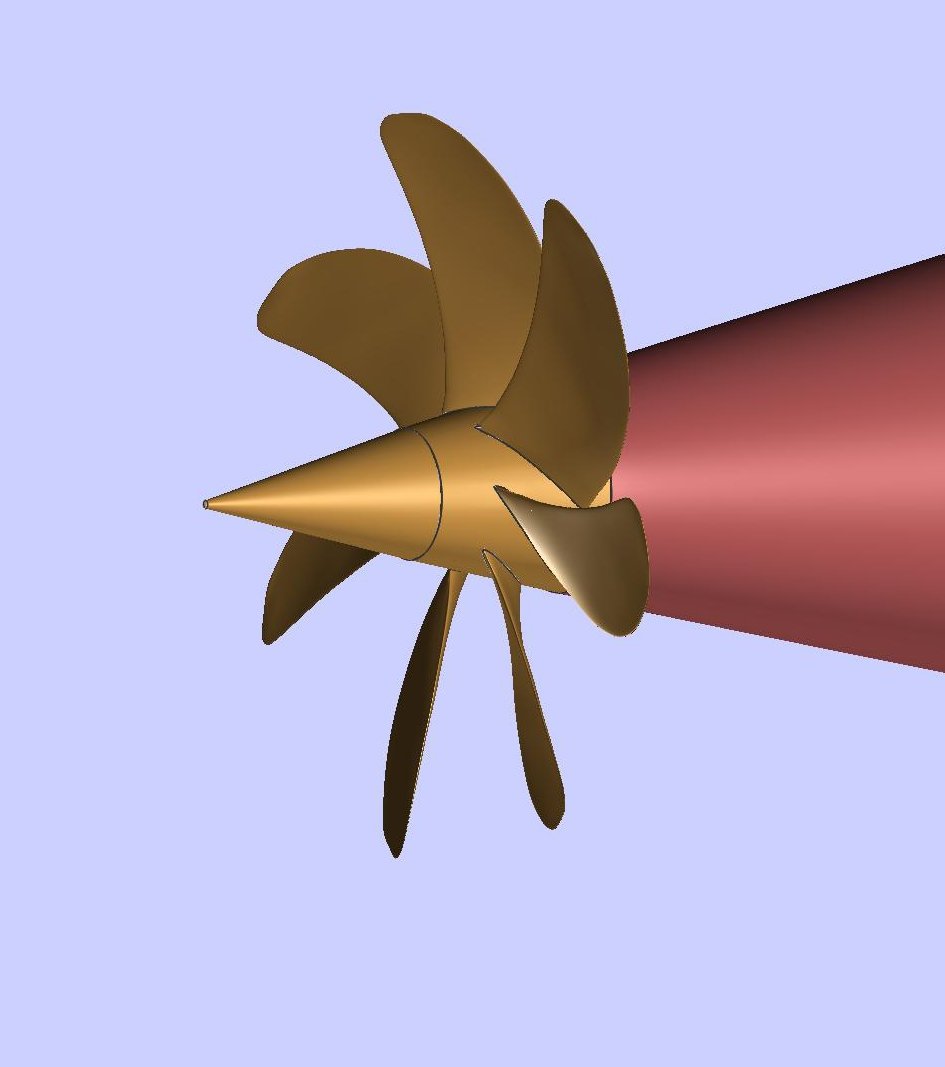
Aft stbd quarter view

Aft port quarter view
Terry
- Roger Pellett, J11, mtaylor and 2 others
-
 5
5
-
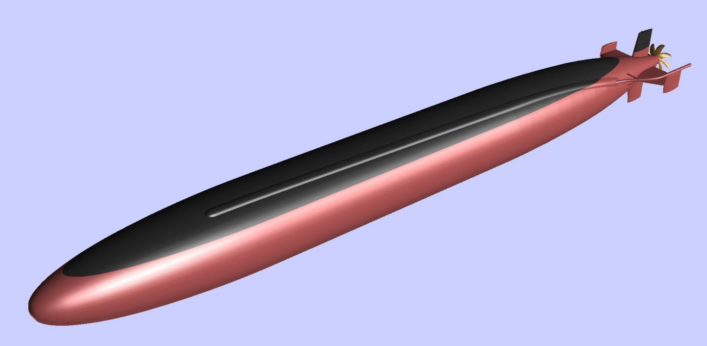
Just for fun, I thought I'd try out whipping out a Sturgeon-class SSN hull using the new background image feature in DELFTship. Setup was really quick. Shaping the hull was another story...
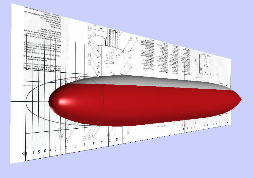
Plan: USS Sturgeon (SSN 637) by Greg Sharpe
Being an old submariner, I may spend a little time on this!
Terry
-
A Guide to the New DELFTship Background Images Feature
Attached are the five parts of a guide I have drafted up to assist modelers who think they want to get their feet wet using DELFTship. It is intended for the complete DELFTship novice, but even those familiar with the program will find this guide useful, I think.
Please read Part 1, which includes an intellectual property disclaimer.
If you have any comments or corrections, please feel free to post them here so everyone can be aware of them (and I can fix them). I am particularly interested in fixing things that are unclear or don't work as intended.
Be sure to install the latest version of DELFTship (13.10 (328 or later)) before you use this guide. It's almost completely incompatible with earlier versions!
Thanks.
Terry
Part 1-DELFTship_Bkgrd_Images.pdf Part 2-DELFTship_Bkgrd_Images.pdf Part 3-DELFTship_Bkgrd_Images.pdf Part 4-DELFTship_Bkgrd_Images.pdf Part 5-DELFTship_Bkgrd_Images.pdf
-
On 1/27/2021 at 10:25 AM, Sailor1234567890 said:
Do you know if Delftship models things like mass, weight, shape etc. to be really useful as a naval architecture program or is it a simple CAD shapes and you have to figure out weight yourself?
Even in the Free version, there are basic hydrostatic functions available. I haven't tried the more complex ones that involve displacements, material thickness and water density, etc. Those don't usually pertain to a modeler. Back-yard boat builders—yes.
Terry
-
-
Just installed the latest free version of DELFTship (v. 13.10 (324)). It appears that there are a lot of improvements. Most obvious to the familiar user are revisions to the menu tabs. However, if you dig into the settings, the user now has the option of creating models in centimeters and inches as well as the standard meters and feet. You can also set the decimal precision, which is really handy, since the default was four decimal places.
This update may be of interest to modelers, who can now create their digital models in the actual dimensions they will build in. [Edit 2/11/2021: Clarified the nature of the dimensioning changes, now that I understand them better!] Former versions had two dimensional unit choices, Metric (meters) and Imperial (feet). If you created a model in one set of dimensions, then changed them to the other, the model would scale in size up or down depending on the direction of the change because the number of units remained the same. Fore example, if you created a 100-foot vessel mistakenly in meters, then changed to feet, the model would downsize to 100 feet. Now, that is OK if you did make the original error in selecting dimensions. However, if you simply wanted to switch dimensions, to understand the size in the other dimension system, that was a problem. With the latest version, you can switch freely among all four dimensional units without any change in the actual size of the model. I found this useful when working on small details in my Galilee model, where creating things in inches was more appropriate than in feet. Scaling down the hull to model-size is easily performed using the program's Scale feature.
There is also a new manual that goes with this version, but I haven't looked at it yet.
Terry
-
I might be able to assist you.
What kind of vessel are you working with?Sorry, had to reread your post again.The DELFTship offset import function is very buggy. If you do a search on the D/S website using "offset import" key words, you will find there is a long history of problems with the function in at least the Free version.
To begin with, I would not try to create offsets of the entire hull and keel assembly. I recommend modeling just the hull between the sheer rail and inner rabbets of the stem, keel, and sternpost, as applicable. If the lobster boat has a propeller skeg or other complicated arrangement around the propeller/rudder, I'd leave that off until the hull form is set.
The import offsets function also doesn't deal well with tumblehome. The hull shape should more or less flare outward from the keel to the rail for the best success. Otherwise, the program tries to connect the rail to the lower parts of the hull inside the widest parts of the hull. It gets really confusing that way!
The DELFTship manual uses a number of terms that may not make sense. I have communicated with the developers about this but nothing has been done. Here are the definitions as I understand them:
- Contour line at each station—This refers to the sheer rail line (top of moulded rail, if applicable) or the outboard deck sheer line if no rail is included.
- Forward contour line—The line described by the x-coordinates of the inner rabbet of the stem at each waterline. Basically, the profile shape of the bow.
- Aft contour line—The line described by the x-coordinates of the inner rabbet of the sternpost (or the centerline, in the absence of an inner rabbet at the sternpost) at each waterline at the aft end of the vessel. Basically, the profile shape of the stern.
- Origin—The origin is the point in 3D space that establishes the zero coordinates of the x-, y-, and z- axes for your model. Normally, the origin is placed at the baseline for the hull at the aft face of the sternpost. For a lobster boat, you may have to choose whether the origin will be at the extreme stern/transom, the extreme bow, or somewhere else that makes sense. The longitudinal coordinate "x" is positive forward of the origin, the lateral coordinate "y" is positive from the centerline outboard; the vertical coordinate "z" is positive upward from the baseline. So, depending on where you place the origin in the setup of your file, you may end up having to deal with negative values (especially x-values).
I would make the baseline the bottom edge of the inner rabbet along the keel. If the keel is raked, then place the baseline at the lowest extent of the inner rabbet of the keel. This permits all moulded hull z-coordinates to be positive.
After you are finished with the moulded surface of the hull, then add the rabbet, keel, stem, and other parts of the backbone.
If I were you, for a relatively straight-forward hull that probably has a hard chine, I'd simply build the stations one at a time from scratch, setting the control points at each station against the boat's deadflat view in the plans. Alternatively, you could import all three views of your hull plan as "Background" views, then use one of the example hull models that comes with the program and move the control points around until you create what you want.
Each method has its pros and cons. And if you haven't worked with the program before, it's got a steep learning curve.
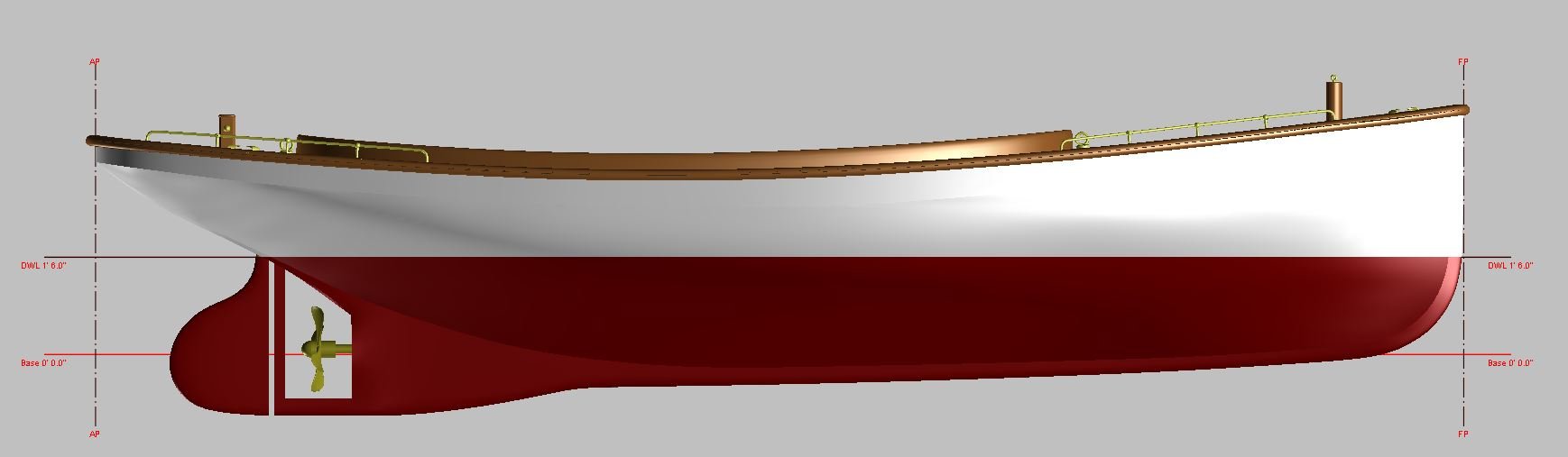
For encouragement, here is my DELFTship model of a "naphtha launch" (c. 1905) that I created from scratch to produce plans for a ship's boat carried by a vessel that my grandfather sailed in back in 1906.

Please feel free to PM me to walk you through any problems you run up against. You may also want to skim through a mini-tutorial on using DELFTship that I made up in my Galilee topic, starting on page 5. That thread as a whole includes lots of photos of my work in DELFTship developing Galilee's hull form.
Terry


CG Model of the Sturgeon-Class Short-Hull Submarine
in CAD and 3D Modelling/Drafting Plans with Software
Posted · Edited by CDR_Ret
Working on the escape trunks, now that the grandfather journals have been delivered to all the cousins and siblings...
The Sturgeons had two escape trunks. These acted like airlocks in spacecraft to allow emergency egress in case the boat was bottomed for some reason. The only difference is that there is high-pressure sea water outside instead of a vacuum.
Basically all US submarines following WW II had the capability to mate with the McCann rescue chamber. This required a flat surface surrounding the upper escape hatch fairing, which was equipped with a haul-down bale, external hatch operating gear, and, later, anchor points for the Deep Submergence Rescue Vehicle (DSRV) snubbers. The flat landing surface on the albacore/cylindrical hulls had to be faired into the hull shape.
So, I tried to illustrate all of these features in this model. The haul-down bale was actually attached to the emergency buoy cable, which was manually released from inside the ship. The buoy carried a cable to the surface of the ocean, to which the rescue device was attached by divers. The DSRVs used the cable to visually guide the vehicle to the stricken sub. The DSRV would mate to the hull above the hatch, then attach snubbers to the four rings to steady the vessel before blowing the skirt dry and entering the sub. In truth, this is a lot of surmising, since none of my boats ever went through a DSRV drill or deployment exercise.
Location of the fore and aft escape trunks. The forward trunk was in the bow compartment and the aft trunk was in the engineroom.
This is the forward escape trunk landing area. I had difficulty modeling these because I don't recall them being so prominent. But there were other things surrounding them like safety tracks, so perhaps they were.
The aft escape trunk.
Since the upper parts of the escape trunks and hatches were located within free-flooding areas and/or ballast tanks, there were a lot of other pieces of gear associated with them that couldn't be installed in way of the pressure hull. These included line lockers, the emergency buoy, retractable cleats, towing fairleads, hydraulic capstans, and so on. Given time, I may actually get to those.
Terry