


Cathead
-
Posts
3,556 -
Joined
-
Last visited
Content Type
Profiles
Forums
Gallery
Events
Everything posted by Cathead
-

Steamboats and other rivercraft - general discussion
Cathead replied to Cathead's topic in Nautical/Naval History
I don't think I have any specific advice or info to offer, but I'm looking forward to this!- 281 replies
-
- 2
-

-
- Steamboats
- riverboats
- (and 3 more)
-
Looking real nice, Mike. You should be very proud.
- 225 replies
-
- 3
-
-
- chaperon
- model shipways
- (and 1 more)
-
Many sympathies, but she's still looking great.
- 745 replies
-
- 2
-
-
- francis pritt
- mission ship
- (and 1 more)
-
Glenn, all the extra detail you put in is a great reference for future work. I'm already thinking ahead to a possible Arabia scratchbuild and this log is really helping me fill in some mental gaps in knowledge. Thanks so much for sharing.
-
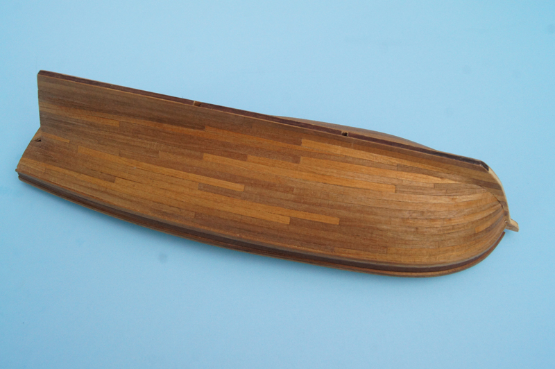
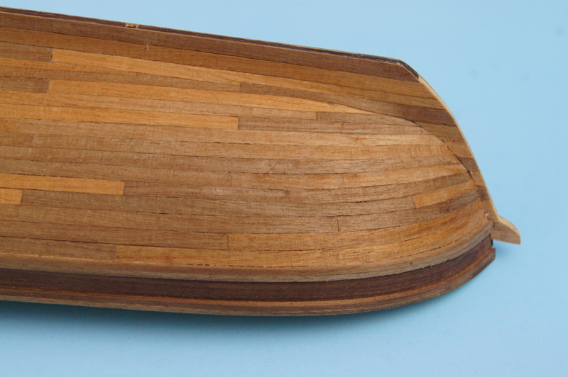
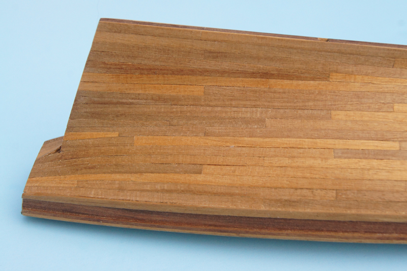
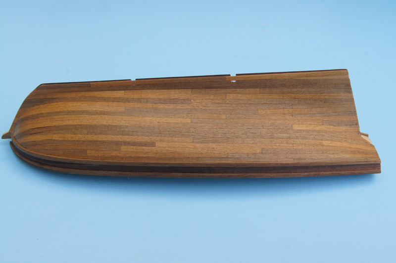
I've finally finished the hull planking, and am fairly pleased with the outcome. I decided to give "accurate" planking at the bow a shot after all, and with much trial and error produced an acceptable result: I really don't like the planking wood provided in this kit. I don't know what it is, I think something tropical, but it's very coarse-grained and splits really easily. It does not take bending well; over and over again as I tried to apply even a gentle edge-bend after thorough soaking, it split length-ways rather than take any curve. But I persevered and finished the hull with virtually no wood to spare. I had tried to apply Chuck's no-soak bending method, using a hair dryer, but this wood wouldn't take it. I had to soak each piece and gently bend it, often repeating this several times, to get the curve needed, and I think I broke two or three for every successful piece. But I really do think it came out reasonably: The stern was, of course, more straightforward, but I used this side to continue practicing proper stealer use. I kept all my joints on a strict pattern and restricted almost all of them to real bulkhead locations. The result is fairly pleasing to me. The camera, of course, highlights every slight gap between planks, but none of that is visible from more than 6" away in person. I've been working on this hull for so long now that it's going to feel strange to change focus and start on other aspects of the build. I'm hoping to start putting more time in again; the last few months have been especially busy between a vacation, the start of a new job, and the always-busy fall season on our farm. If winter ever arrives here in Missouri (it's still over 80 F), this build will start progressing again. Thanks for checking in on me.
- 96 replies
-
- 10
-
-
- topsail schooner
- revenue cutter
- (and 3 more)
-
Thanks, Glenn. I haven't stopped this build, I promise, it's just been a very busy stretch for me. I think I'll be able to post an update next weekend, showing what I've been up to on the port side planking.
- 96 replies
-
- 5
-
-
- topsail schooner
- revenue cutter
- (and 3 more)
-
Wait, so Heroine's pilot house was accessed only from below, not from the hurricane deck? That's also different from later practice. I wonder why? Looks great as always, thanks so much for sharing all this.
-
Glenn, Thanks for the detail on shaping your trusses; it's interesting how much force the upper beam placed on the lower. When I built Bertrand, I bent my upper beam in place on the model so that the entire structure of the hull or cabin was there to push back against the curve. I wonder if the original builders did something similar; building the frames in place instead of pre-assembling them? Isn't that how older buildings were constructed, with pre-built roof frames being a relatively modern invention? I think your method produces an excellent model, as it allows you precise accuracy in the curve; at a model scale even the slightest variation shows up as "wrong" whereas in the real thing there could probably have been a bit more tolerance. Just a thought, I don't know much about this. As for the outhouse, I do see the port-side hole, thank you. It's really interesting that they didn't provide more facilities for cabin passengers (I assume you meant "passengers on the boiler deck" unless Heroine has a second deck of cabins above this one?). I feel sorry for the steward who had to empty two large chamber pots from the boiler deck every morning. It does seem to work out nicely that the main deck outhouse has a staircase leading right to it from the boiler deck, and that it's essentially isolated from the engine room and working areas, which would allow cabin passengers (even ladies) to reach the facilities with minimal contact with crew, machinery, cargo, and deck passengers. On the later boats, with outhouses on the boiler deck, I've wondered what the "lower classes" did; were they allowed up on the boiler deck with the "better classes" to use the facilities, or what? That's enough taking this thread off the rails again. Think of Heroine as archaeopteryx, the steamboat with feathers.
-
Bob, I agree. As a geologist by background, Heroine keeps reminding me of a transitional fossil, an unusual lifeform that helps us better understand evolution. Heroine certainly fits that role as a link between early rivercraft and the apex of riverboat design.
-
I love the precision curves the machine-cutting makes. Produces a really clean run of the hurricane deck, much nicer than my hand-bent attempts. I just noticed, did Heroine not have outhouses hanging off the stern like most later boats? Where were the facilities?
-
Nicely done!
-
Really nice, Mike. I've been away on vacation and was looking forward to catching up on your progress.
- 225 replies
-
- 1
-
-
- chaperon
- model shipways
- (and 1 more)
-
Very nice progress, Mike. As to your question, if it were up to me I'd paint those strips along the wall ends, but it's the kind of detail you have the right to decide on to make it yours.
- 225 replies
-
- 3
-
-
- chaperon
- model shipways
- (and 1 more)
-
Well, as my approach to this kit evolves, it's becoming something quite different from what I initially intended, but also something quite interesting in its own right. I've planked the starboard side following the "go with the flow" approach, allowing the kit-supplied planking to curve as it desires. It's obviously not accurate, but it was good practice for fitting planks, and I think it came out nicely overall other than the un-prototypicalness of it. Certainly the vast majority of viewers here will never know the difference; Mrs Cathead cooed when she saw the results. There are two noticeable errors: a couple planks which didn't quite seat properly near the bow, and a notch at the keel where I screwed up cutting out the notch for the display stand. This was my first attempt at using stealers on any model, and I think it worked well at the stern. I had considering painting this side if the planking hadn't come out well, but after sanding and oiling it, I think I like it this way. I never intended a natural-wood model, but as that's what it's evolving to be, so be it. The next step is to decide whether to finish the port side the same way for consistency, or to order a few sheets of wood to try my hand at spiling an accurate run of planks. This would look strange from head-on, but as it won't be displayed that way, it may not matter, and may even be a point of conversation to be able to display two different planking approaches at once. I have time to think about it, as we're about to depart for vacation in Boston and Maine. I'm looking forward to visiting the Constitution, and hopefully dropping by BlueJacket in Searsport, ME. Thanks for reading.

- 96 replies
-
- 11
-
-
- topsail schooner
- revenue cutter
- (and 3 more)
-
I quite enjoyed building this kit recently, and look forward to seeing your take on it. Have fun!
-
Looks real nice!
-
Yeah, I'm not happy with the wood either. Lots of really rough-cut edges even on the thin, "high-quality" planks. With this kit, the problem goes beyond bad translating, because the text and drawings quite literally don't match up regardless of how you interpret the text, and the drawings themselves repeatedly contradict one another. I can't just ignore the text because the drawings are literally wrong. Can't imagine trying to re-translate again into another native tongue. It's been a really good learning experience and I think it'll come out attractive, but this is the kind of kit that destroys beginners.
- 96 replies
-
- 6
-
-
- topsail schooner
- revenue cutter
- (and 3 more)
-
Thanks, cog, that's essentially how it seems to me. Are such kits really so sloppy, providing drawings that are completely impossible with the materials provided? I keep getting into trouble on this kit by assuming that the directions can't be as bad as they really are. I was expecting poor translation and incomplete directions, not blatantly wrong over and over again. I build on a tight budget, so will have to investigate what it'll take to do this right.
- 96 replies
-
- 5
-
-
- topsail schooner
- revenue cutter
- (and 3 more)
-
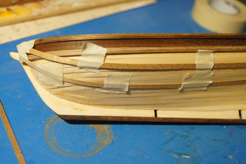
Help! I am really struggling to set up the second layer of planking, and could really use some advice. The basic issue is, I can't reconcile the kit's instructions and materials with everything I've read and understood about planking. Here's a photo of the hull, with several lengths of the kit's thin walnut strips supplied for planking, taped to the hull along their natural curve. That sweeping upward curve goes against everything I've ever read in planking tutorials. Planking is supposed to look something like the first layer I did, where each strake runs loosely parallel to the deck and wales. Yet on this hull, with its sharp bow, it requires severe edge-bending to achieve something even close to that, which is why my first layer looks so rough and required so much sanding. I simply cannot understand how I'm supposed to shape these 4mm wide walnut strips into a smooth run of planking that stays horizontal, rather than the upward curve you see here. I had thought that more tapering would be enough to do a better job on this layer, but it won't be, not even close. I understand that the other option is spiling, i.e. taking a wide piece of wood and cutting out the unusual shape that will bend naturally into the needed curve. But the kit doesn't provide any guidance or materials to do that: it simply gives you a bundle of these narrow walnut strips and says "plank the hull", with a drawing showing nice, parallel lines of planks that are, as far as I can tell, a physical impossibility to achieve with these materials and hull shape. If I begin to lay even the first plank parallel below the wales, it won't take the inward curve of the hull at all, just bends outward dramatically to produce a brutal clinker effect. I got away with it using the thick first-layer planks and lots of filling and sanding, but know I won't do so this time with these really thin and fragile planks. No amount of tapering helps; I've tested a few strips tapered to half the original width, but the curve is so severe it doesn't work. All the planking tutorials I've looked at are either for ships far more bluff-bowed than this one, which seems to ease the problem, or call for spiling, which I can't do with the kit-supplied materials. Of the few build logs for this kit, everyone that got this far in planking just did their own pattern where the planks wanted to lie, not the "authentic" run that all the guides say to do. I looked at a few similar kits with good online instructions, all of which said to spile when necessary. What do I do? I'm tempted to just to plank as the planks want to lie, using stealers and such as necessary, and leave aside authenticity. But the accuracy stickler in me doesn't understand how the real thing was planked with a hull shape like this. Did the real builders saw out massive wide boards to spile narrow curved planks from? Did they put severe edge-bends on oaken planks and plane away the clinker afterward? Both seem doubtful to me. So I just don't understand how to proceed. And I can't do much more experimentation, since the kit has almost no spare material included and these strips are already quite fragile. I have to get it right the first time. Or, at least, get once side marginally right then do it truly right on the "display side". But I just don't know how to proceed, and have been puzzling over this for weeks while delaying by doing other aspects that I do understand. Help?
- 96 replies
-
- 5
-
-
- topsail schooner
- revenue cutter
- (and 3 more)
-
Huh, I've never tried IPA while modelling; I usually stick to rye whiskey. You're making good progress.
- 225 replies
-
- 4
-
-
- chaperon
- model shipways
- (and 1 more)
-
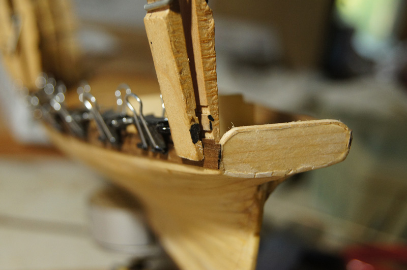
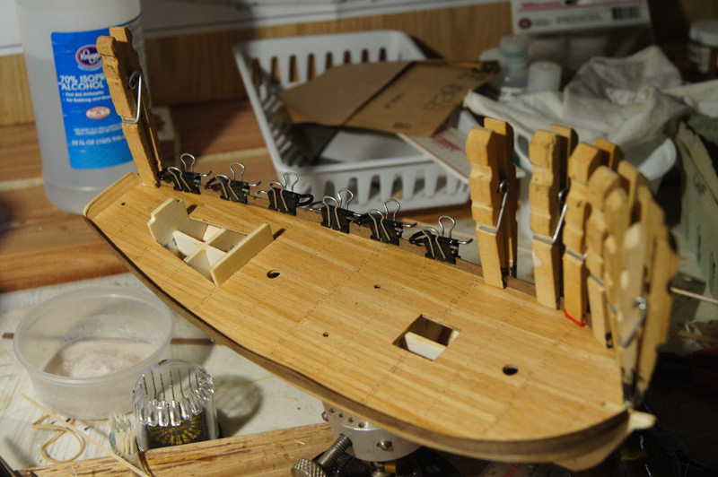
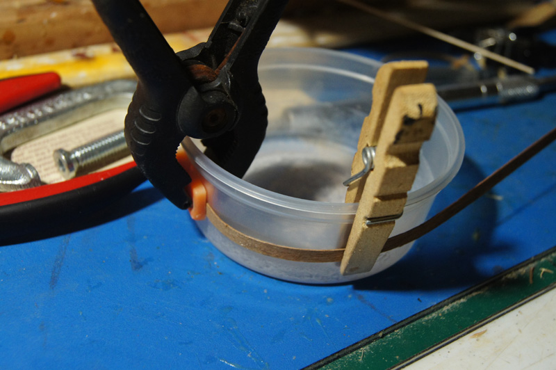
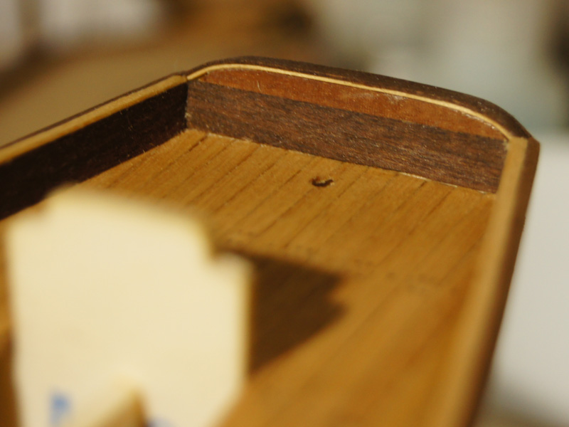
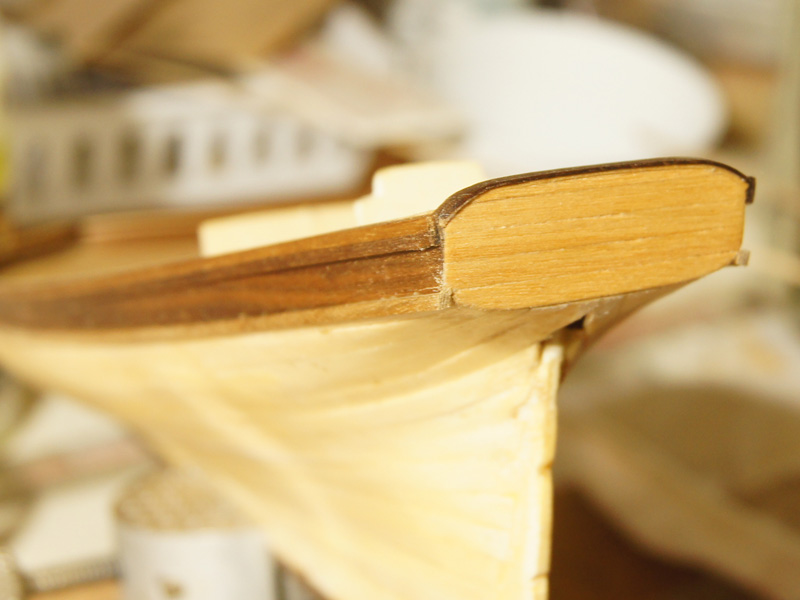
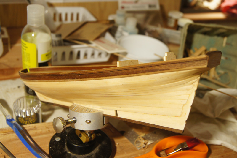
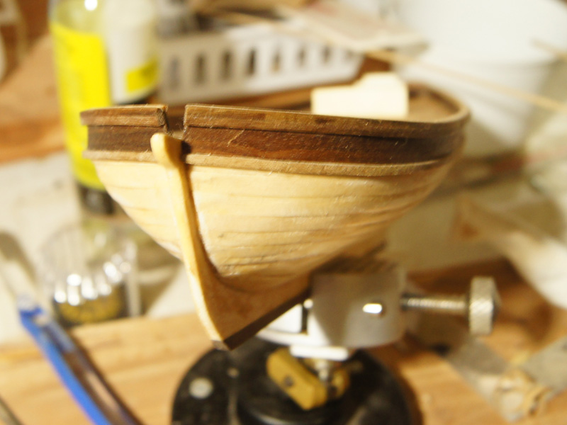
Bulwarks, wales, and transom This was an interesting process of adapting my skills and intentions to poor instructions and kit layout. Lots of photos below. The bulwarks begin by gluing two thin strips of walnut together lengthwise, overlapping halfway. You're then supposed to bend and glue these to sit over the edge of the deck, so that the lower strip forms the first strake of planking and the upper strip sits inboard atop the deck. The photo above sort-of shows this cross section, along with the beginning of my take on the transom. Here's another view. Look at the starboard rail, and you'll see one reason why I don't like this approach: it's really easy to get waves or dents in these thin strips as you try to attach them firmly to a narrow strip of the hull. I'd prefer setting up thin stanchions first and gluing strips to those. This photo actually shows the next step, adding several more layers of thin walnut inside the outer bulwark to stiffen and thicken it. Here's how I bent these strips, using a plastic dish with about the same radius as the bow, soaking the strips overnight, then clamping them into a curve until dry. This thin walnut is really prone to breaking, and the kit offers no extra material, which has been an annoyance throughout the build so far. I had to glue several strips back to together after they shattered, and attempt to hide the joint as I had no spares to replace them. After you're done with this, you're supposed to have a ledge on the outboard side, along which you run two thicker square strips of walnut to widen the top of the rail. The directions show these two strips lining up perfectly with the inner bulwarks to make a nice, smooth surface. They don't. In the photo above, you see the significant gap remaining between the top of the inner bulwarks, and the much higher outer line of square walnut strips. This was most annoying, and I decided I had to fill that gap with wood to bring the whole thing level. Having no spare walnut, I had to use scrap basswood from my stash. I didn't think this would matter, as this whole assembly gets painted anyway. Here I'm inlaying the basswood at the bow, after bending it to a proper curve. On the port side, you can again see the gap I'm trying to fill. Interestingly, by the time I'd finished and sanded everything smooth, it ended up looking really good! The thin basswood strip sets off the darker walnut nicely, and Mrs Cathead cooed when she saw it. "You're not going to paint over that, are you?" Hmmm. So after some thought, I decided to see if I could finish the above-deck area as natural wood. I formed a transom to my liking, and laid a strip of basswood then a strip of walnut across the upper curve, which also turned out nicely, blending the basswood inlay along the rails with the walnut exterior. I planked the stern with scraps of remnant decking, and smoothed everything to fit. It's not the transom I set out to make, but I think it works. I still can't easily envision the 3D geometry of the curved transoms some of these craft had, and since this is a fictional one anyway, I'm going with what looks pleasing to me. So here's how she looks now, with the first line of the wales attached. I rubbed everything down with a natural wood oil I use on my kitchen counter, to protect and darken the wood (actually, the lower wale hasn't been oiled yet, so it looks lighted, which shows you the difference). I like the effect, and so does Mrs Cathead, my primary audience. I should have taken a higher-angle photo of the basswood inlay inside the rails, but you can see a hint of it.
- 96 replies
-
- 9
-
-
- topsail schooner
- revenue cutter
- (and 3 more)
-
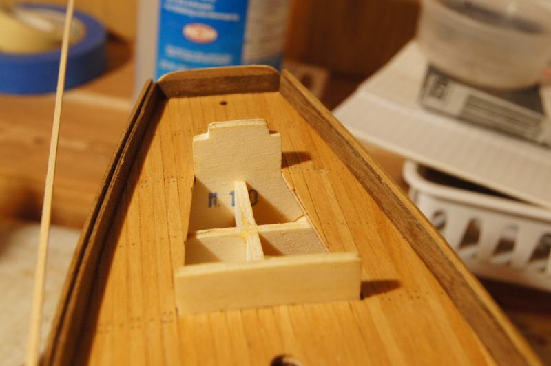
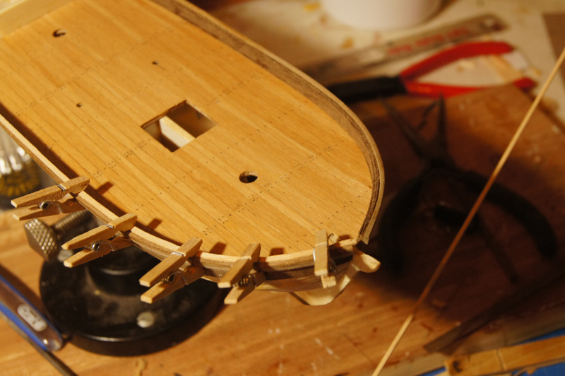
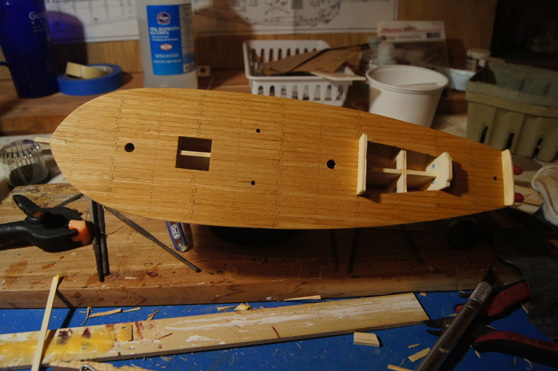
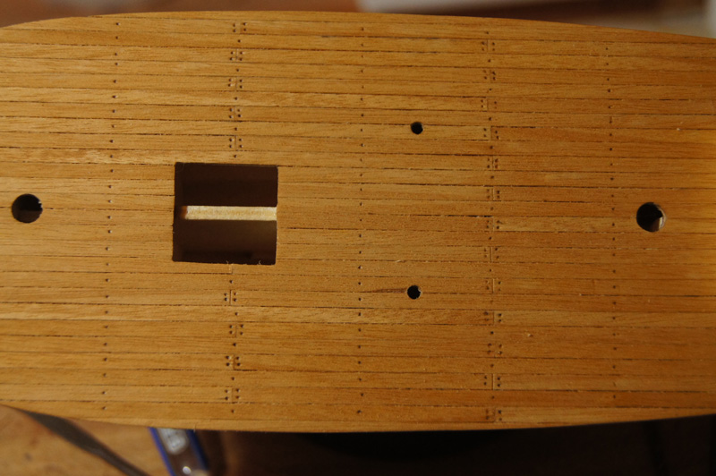
Finishing the deck Here's how I finished the deck. I embossed small holes into the deck planks, using a smaller nail than in my tests above, and gently filled each by pencil. This kept the pencil mark just below the sanding level, so I could finish the deck without smearing anything. Once I was done, I sanded and oiled the deck. I had to decide on a treenailing pattern, and you can see what I went with. I first just did the plank ends, but it looked wrong as the lines of treenails just had too much open space between them. I assume in reality these planks were attached at every deck beam, but I thought that would look too busy at this scale. So I made a single line halfway between each line of joints. To my eye, it balances the appearance of the deck and I'm pleased with the outcome. The only downside is that despite using a straightedge to lay out the planking, I clearly didn't do a perfect job and some of the joints wander a bit. I think this won't be noticeable once the model is finished; it stands out now because the deck is wide open.
- 96 replies
-
- 6
-
-
- topsail schooner
- revenue cutter
- (and 3 more)
-
Any jigs/suggestions for coiling gun rigging rope on decks?
Cathead replied to MartinJ's topic in Wood ship model kits
I agree with Dylan, the double-sided tape works fine. You do need a reasonably strong tape; I switched brands and the new one isn't strong enough to hold the line down. Also, don't over-coat the coil with glue, or it'll soak down in and glue the coil to the tape, making a mess when you try to remove it. And yes, it's far easier to make coils on the bench and install them. Same goes for "hanging" coils like those on belaying pins. -
Almost done! You're doing a fine job.