


Cathead
-
Posts
3,550 -
Joined
-
Last visited
Content Type
Profiles
Forums
Gallery
Events
Everything posted by Cathead
-
 Seems reasonable? One of those things you may notice but no one else will, and that will vanish into the overall coolness of the finished model. Would it work to sand down the outer edge a bit to minimize the thicker shadow, or would that mess up the staining?
 -
I can't quite tell how that blends into the rest of the run of planking, but of course you have a better in-person view of how it all fits together.
-
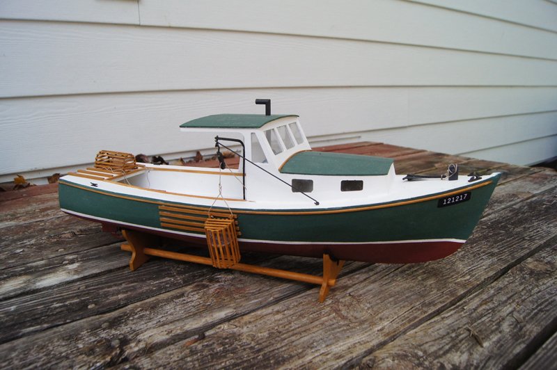
Welcome from central Missouri! I've built a BlueJacket lobster boat and had a great time with it. Here's a review I wrote that might be of interest to help you avoid a few quirks.
-
When you start typing a reply, look at the toolbar immediately above the text box, which has all sorts of text formatting tools. Hovering your mouse cursor over each one will tell you what it does. About halfway along is one that looks like a chain that lets you link text. So just select and copy the URL for a given log, then select whatever text you want to represent the link, then click the link tool and paste it in. So, for example, the URL for my build log is https://modelshipworld.com/topic/24932-viking-longship-by-cathead-dusek-135/ If I want to link it in the text "the link to my build log", I copy the URL above, select "the link to my build log", click the link tool, copy the URL into the URL box in that tool, and the result is: "the link to my build log" If you want to link to a specific post within a log, look for the number in the upper right corner of the post (i.e. #20). Right click that and select "copy link location". Now that you have the link to that specific post, use it with the above instructions. Is that clear enough? It's always hard to write these things out.
-
Cool, another Viking log to follow! Just for the sake of possibly pedantic accuracy, the image you show is the frame Jack Aubrey built for his Gokstad ship, not the one I built for my Skuldelev 2 ship, though mine is based on his (I want to make sure he gets full credit).
-
On the brickwork, I think I used printed brick paper (from model railroading) on the Bertrand and made my own wooden bricks for Arabia. I don't think the former would hold up at your scale. There are a lot of model railroad molds out there intended for casting various building parts in plaster, I wonder if a brick pattern mold could be found that would look right? That would give you a nice 3D effect without having to cut out and shape lots of bricks.
-
Exploring the maritime history and geography of Chile
Cathead replied to Cathead's topic in Nautical/Naval History
German, thanks for reading! Really cool to hear your perspective on being directly involved in so many of the vessels we saw. Can you give me any insights into the basic fishing craft? -
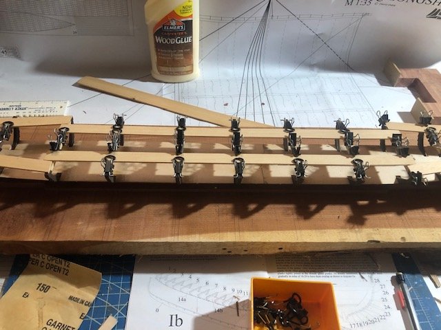
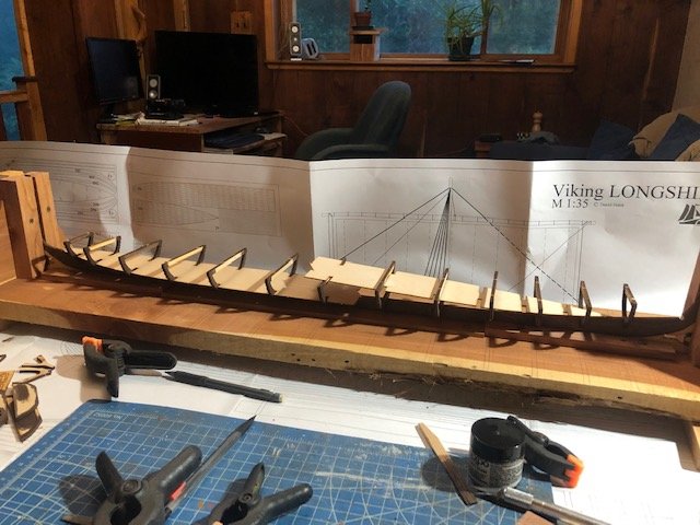
Next step is to add bracing to the top of the frames to hold the whole assembly stiff while planking. This is another example of the instructions being really vague; they refer to using a numbered part for this, but there's nothing in the laser-cut sheets or plans with that number. The kit comes with various strip wood, but there's no parts list to tell you what's what or what it's intended for, and all of it seems to be nicer wood than I'd use for throwaway temporary bracing. So I just used stuff from my scrap bin instead. I did the bow and stern first, using shorter pieces so they'd stay near the outer edge of the frames: Then filled in long straight strips in the middle: Next step is to remove the hull from the building frame and start planking. I'm trying to decide if I want to build/adapt a new building frame to hold it firmly upside down, or just work on it freehand.

-
¡Bienvenido a Model Ship World, German! Me interesa que usted es de Chile. En el año 2018 mi esposa y yo viajamos en su pais para un mes, y pasamos mucho tiempo largo de la costa. Yo escribí sobre esto viaje a Chile en MSW, ¿quizas le interesta leerlo? Planeamos volver, pero ahora no podemos por el virus. Es muy desfortunado, por que durante nuestro viaje nos conocimos a mucho gente y creemos que los Chilenos son muy simpaticos y interesantes. Mi español es limitado, pero he trabajado duro antes del viaje y después, por que los dos queremos volver a su país. Espero que puede me entender. ¡De nuevo, bienvenido!
-
Hah, good point. It would be cool to simulate some of the stone ballast, maybe I need to leave some of the deck planking off. Someone's log also has a super-cool real-stone anchor that I want to copy.
-
Chaperon by joep4567 - 1:48 - Sternwheeler
Cathead replied to joep4567's topic in - Build logs for subjects built 1801 - 1850
Everything looks real nice. -
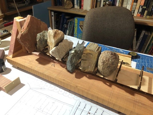
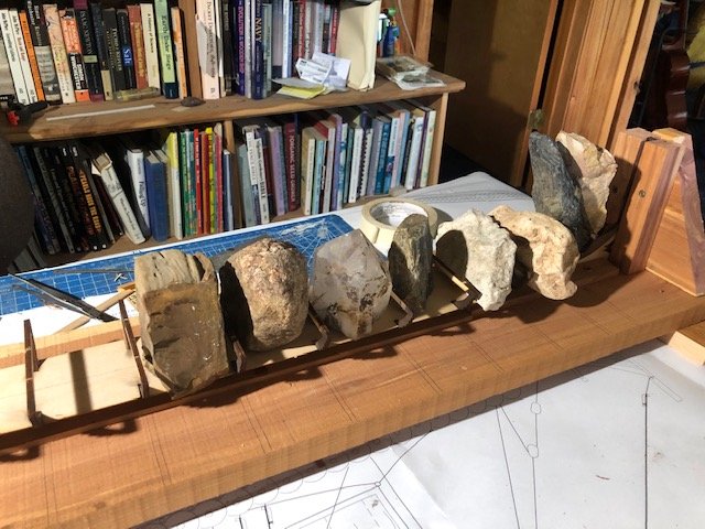
Time to add the false decks. It took quite a while to carve the frame slots out enough for these to fit properly, but I got there eventually. Part of the slowness was the need to keep sliding the decks back inside the frames to check the fit, which is a delicate process. Once I felt they'd fit, I worked out how to hold them in place while the glue dried. Several people have used various combinations of rubber bands and clamps, but I drew on some resources from my geology background. First, I spread a thick layer of glue on all the keel/frame surfaces, as the fit isn't perfect in a few places, not worrying about spillover since none of this will be visible from any angle: I then used rock samples between each frame, which seemed to work nicely with a minimum of fuss. I did one half of the frame first, then the other. So far so good.
-
Nice start to an interesting build. I'll look forward to following your progress. If it's of interest, feel free to check out my series of photos from a full-scale Beagle replica in southern Chile, which might be helpful or at least inspirational.
-
Cool! Rigging always helps tie a ship together.
-
Chaperon by joep4567 - 1:48 - Sternwheeler
Cathead replied to joep4567's topic in - Build logs for subjects built 1801 - 1850
Cool! -
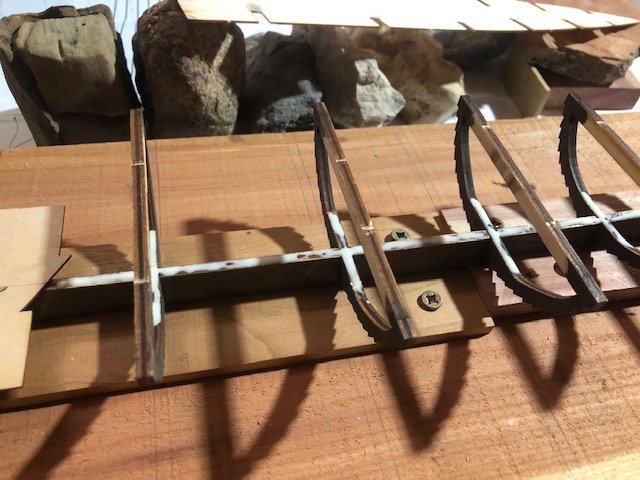
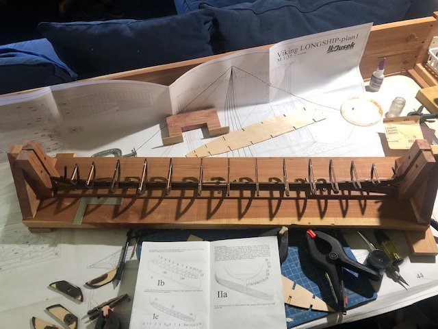
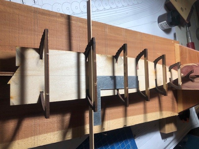
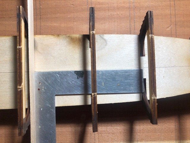
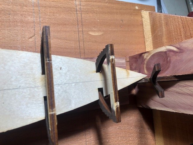
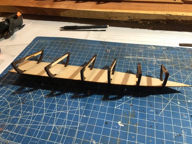
Got all the frames installed, looks pretty cool: I started test-fitting the false deck that gets inserted within these frames, and immediately found the next problem: it doesn't line up straight with the frames and keel. It has slots that are supposed to fit over every frame, but if you line up the deck's centerline with the keel, the slots are at an angle to the frames (i.e. the frame don't fit into them), and if you slot all the frames into the deck, the deck doesn't line up with the keel. Here the latter is shown; check the centerline at both ends: Detailed view amidships: Detailed view at the bow: This problem is consistent throughout the deck; all the slots fit neatly around the frames, but the whole deck is off-kilter. So this could have two explanations: (1) I got the angle of the frames consistently wrong (not square to the keel) when gluing them in or (2) the deck slots aren't cut quite square. I double-checked all the frames relative to the keel using a square, and they're all as square to the keel as I can determine. I then placed a strip of wood across one of the frames and placed a square against it to check the orientation of the deck's centerline, with this result: You can clearly see the off-angle there, which seems to imply that the deck slots weren't cut quite square during manufacture (option 2). Even if I installed the frames crooked, if the deck slots were cut squarely, the deck's center line should be at 90° to the frames when they're fit together (the measurement above is independent from the keel). Does that seem like the right conclusion, or am I missing something? Either way, it seems like the best answer is to file the deck slots wider until the deck fits properly and squarely with the keel. As this gets covered with another layer, I don't think it matters if the slots are a bit loose.
-
Travis, I added full sails to my topsail schooner revenue cutter and used bond paper and was happy with that result. See log linked in my signature; see also this thread I wrote about using paper. Also, on installing items on the deck, it can help to drill a small pin into the bottom of the item and then insert it into the deck; this helps hold such items firm against slight but inevitable knocks. Nice work so far!
-
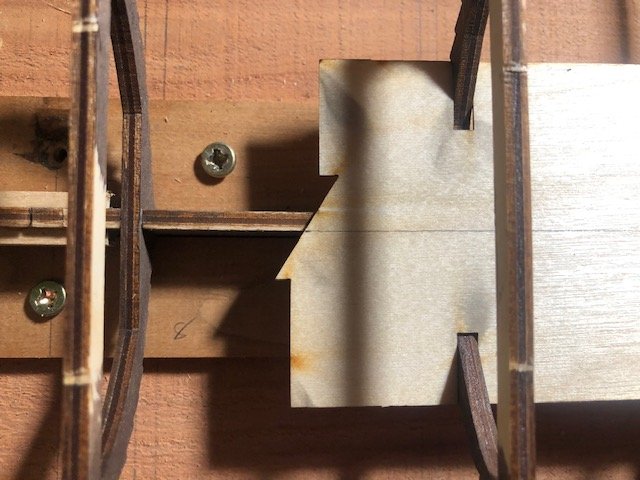
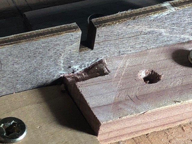
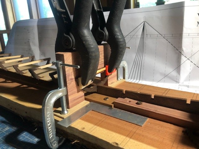
So the instructions for this kit have what I think is a major flaw. Along with the frames, there is a two-part false deck that goes within the frames. The instructions say to glue the frames to this false deck first, and then install onto the keel. That would look like this (dry-fit for demonstration purposes): However, as pointed out by Binho for the smaller version of this kit, this has a serious flaw: The false deck is flat, while the keel is not; the latter has a clear rocker (curve) toward stem and stern. So if you glue the frames to the deck nice and square, they'll start leaning toward the center as you approach the stem and stern. This means they won't actually fit nicely with the vertical slots in the keel. So it makes more sense to attack the frames first, then slip the false deck in. To make sure this would work (i.e. is there enough room to slide those deck pieces through the enclosed frames?), I did another dry-fit. It does work, you can slide the deck pieces in afterward: With that confirmation in hand, I started gluing in frames using my homemade jig: The frame is first lined up with the horizontal lines on the jig to ensure it's level, then clamped on (black clamps). I then use a square to ensure that it's even across the keel and clamp the jig's feet to the build board (silver clamps). I've done a few this way and it's worked great. I ran into one small problem. I thought I'd been careful to ensure that the horizontal strips holding the keel in place were low enough to not interfere with the frames, but got it wrong in one place: the very next slot in the image above. I fixed this by using a small chisel to gouge out a slot for the frame to enter. This was especially easy as the cedar is soft and easy to carve: I nicked the keel, but I don't think it'll be visible in the final model. So now I'm just moving forward gluing each frame in place, which is slow as I like to let the glue set well before moving on to the next frame as the workspace is tight. I probably could have built a second jig to work from the other and and double my rate, but don't feel like it, so will just keep plugging away. Thanks for reading! Hopefully this will get more interesting soon as the ship starts to take shape. Early steps are always a bit dull.
-
Chaperon by joep4567 - 1:48 - Sternwheeler
Cathead replied to joep4567's topic in - Build logs for subjects built 1801 - 1850
Nice work! -
Yes, the clamps are made by combining multiple pieces. It's 2 for 3, as you take the two arms out of one and each arm gets inserted in another clip. The "tubing" was just how some of them came, I have both types and don't think it matters. I keep the original pieces so I can always put them back together the normal way if desired. I have various types; sometimes it works well to insert an arm from a larger type into a clip from a smaller type, but you can experiment with what works best for you. Also, if you haven't run across this idea yet, inverting normal clothespins makes them much more useful. Those are also shown in the image above. You basically flip the two halves over within the spring, giving a smooth clamping surface. This also makes the grip a LOT stronger. I have a bunch of these and use them all the time.
-
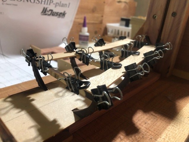
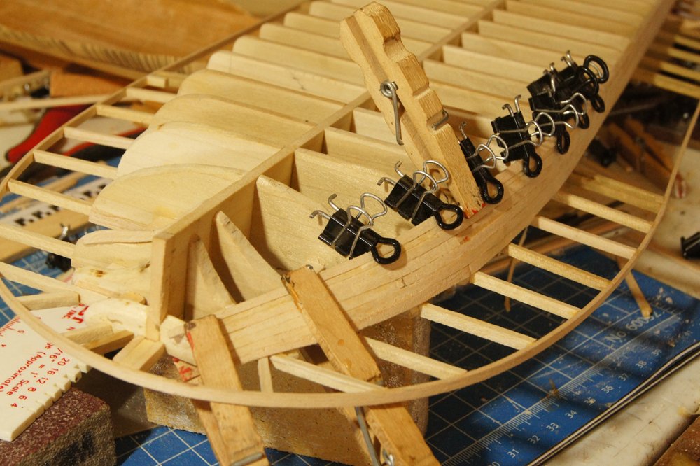
Looks good. My normal procedure (everyone has a different one) is to use warm water, as I've read that the heat helps loosen the wood fibers. I think it partially depends on the thickness of the plank. What kind of clamps are you using? The sort of three-dimensional geometry that's needed to hold a plank to a frame is pretty complicated. Here's one of my favorite styles (not my original design), made by adapting standard office-supply binder clips. These are great because they hold really solidly to the frame/bulkhead, but don't directly clamp onto the wet plank, minimizing the chances of deformity (photo from my last build): Obviously I'm also using more typical clamps here as well, but in this case I'd tested and found that I wasn't getting too much plank compression.
-
Chaperon by joep4567 - 1:48 - Sternwheeler
Cathead replied to joep4567's topic in - Build logs for subjects built 1801 - 1850
When building paddlewheels from scratch, I've found it surprisingly difficult to get them all perfectly the same, and even tiny variations will ripple throughout the wheel once you try to line up all the spokes with straight buckets (the horizontal planks that tie the spokes together). It can help to define your first wheel as the pattern, then build each subsequent one directly on top, using clamps or pins to guarantee that they match. It also helps to clearly mark one spoke as the starting point for when you try to line them up later. Again, even tiny variations in the pattern will cause problems later, so knowing which is spoke A on each ring is really helpful, as is which way it should be oriented (mark the starboard or port side of each ring). Otherwise you can end up rotating them around like tumblers in a lock, trying to find the right combination. -
Just read through this build, great work. Love some of the extra details like the anchor, I may use that for my current build.
-
Nice problem solving so far, glad to hear you're enjoying your first build! If possible, I'd strongly suggest experimenting with plank bending on any similar scrap material you may possibly have around, just to get a physical sense of how it works and feels. Many skills in wooden model building end up being tactile as much as intellectual, in my opinion, and there's nothing like feeling how something works before you do it for real. One note when using water/soaking to bend planks: wet planks are compressible and can receive damage while drying (such as from an overly tight clamp). It's so frustrating to bend a wet plank, then find out later it has a big clamp divot in it. This is especially true for open boats like this where the planks can be seen from both sides (at least the upper ones). This is another case where experimentation with scrap will help you figure out what you can and can't get away with. I'm not familiar with this model, but from the page you showed, it looks like the planks are pre-spiled? Meaning that they aren't straight strips but are pre-cut in a curve that will help them take the shape of the hull? If so, that eases your job considerably. Planks that come with bundles of straight strips mean a lot more difficult bending work. On the other hand, pre-spiled planks make it all the more important to practice your methods first since you only have one shot at each plank. Great start and I can't wait to see where you go with this.
