Cathead
-
Posts
3,526 -
Joined
-
Last visited
Content Type
Profiles
Forums
Gallery
Events
Everything posted by Cathead
-
 Sampson posts went out of use before this period, they were an early style only. There won't be any trussing above deck other than the regular superstructure.
- 599 replies
-
- 4
-

-
- sidewheeler
- arabia
- (and 4 more)
-
Roger, Both Louis Hunter and Adam Kane note that longitudinal hog chains were first developed in the 1840s and probably weren't in widespread use until the 1850s. So their apparent absence in your 1848 photo isn't necessarily indicative of their use or not. Both of those resources, as well as Bates, make blanket statements that sidewheelers used longitudinal hog chains, but that once the engineering had been worked out (i.e., probably by the mid-1850s), they tended to remain below the boiler deck and thus wouldn't be easily visible in photos. But they'd be visible on a model viewed from the side. So I think I'm well within reasonable modeller's license to install them on Arabia. Bates also notes, in a passage I missed until rereading carefully, that some boats' knuckle chains (those supporting the hull) remained below the main deck, which is a good enough reason for excluding them above-decks on Arabia. In several re-readings, I can't find a clear answer on the use of cross chains (supporting the guards) for narrower non-cotton-packet boats like Arabia. It's obvious they were abundant on wide boats, but no one really discusses their uses on other boats. A clear argument could be made that Arabia didn't need them other than near the wheel, but also that a cautious builder or owner might have had a few installed further forward for greater strength. As for the hog chains, I think reasonable modeller's license allows the judicious inclusion of cross chains in the model for visual and historical interest.
- 599 replies
-
- 5
-
-
- sidewheeler
- arabia
- (and 4 more)
-
Real planking always looks better. Are you leaving it the natural wood color or planning to paint/stain the typical red color?
- 133 replies
-
- 1
-
-
- chaperon
- model shipways
- (and 2 more)
-
I think the single biggest mistake newcomers make is getting in over their heads. You do NOT have to start with a big rigged ship. Building one or two small craft (rowboats, launches, fishing vessels, etc.) will let you test almost all the skill sets, methods, and materials you'll need for your dream build, and they're a cheaper and faster way to go about it. The time you "waste" doing that first will almost certainly be saved in the long run when your dream build goes faster and smoother once you know what you're doing. The second biggest mistake is being cheap and looking for deals rather than focusing on quality. Lots of people get frustrated when they buy a random kit that looks pretty but is poorly made with terrible instructions, because they didn't bother doing some basic research on which manufacturers are actually worth buying from. Also, there's a risk to working on older kits, because materials can age poorly and kit quality has improved. It may feel good to dust off that 20-year-old kit you always wanted to build, but there's a very good chance a kit made last year will be a lot more pleasant to work on.
-
Mark, as I said above, upper-river boats needed hull flexibility and lightness to deal with shallow-water conditions, which is why I would expect them to rely on chains as much as or more than hull bracing. However, that doesn't mean they needed lots of them, given their relatively light hulls and cargoes. Lower-river boats could afford to have more interior hull bracing (and thus more rigid hulls) because of calmer and deeper river conditions. They still needed chains to help support those huge hulls and their extreme length-width ratio, but especially required lots of transverse chains to support their extra-wide and heavy guards (see Kurt's images of the J.M. White, above). My conclusion from all this is that something like Arabia wouldn't have had as extensive a network of chains as you see on the J.M. White, but likely still needed a few to support the needed hull flexibility of an upper-river boat. I.e., Arabia shouldn't look like a spiderweb, but should probably have a few transverse chains near the wheels and possibly one or two further forward, then one or two longitudinal chains to help support the hull's flexing over sandbars and such. I had no idea this would generate so much discussion, maybe I should have put this question in the general riverboat thread. Oh well.
- 599 replies
-
- 5
-
-
- sidewheeler
- arabia
- (and 4 more)
-
Carl, from my perspective (and I'd be interested in Kurt's and Roger's input), the internal bracing and the hog chains serve slightly different purposes. Internal bracing makes the hull more rigid, which is particularly useful in ocean-going vessels but potentially problematic in riverboats because too much rigidity means you can actually break the boat's back in shallow-water river conditions (this would be less of a concern for deepwater steamboats on the lower Mississippi like the big cotton packets). The chain system allowed for a certain amount of hull flexibility that was needed in these conditions while still providing support; it also meant you could readjust the tension needed as the boat worked and aged. So most boats, especially by the 1850s, used a combination of both as relying on one or the other exclusively would be problematic. Also, extensive wooden bracing gets heavy and expensive rather quickly, and upper-river boats needed to be light and cheap. A few iron iron rods were a lot more practical in this sense than lots of custom-cut oaken braces. Finally, upper-river boats tended to carry proportionally more cargo in their holds than the bigger lower-river boats with their huge stacks of cotton on deck. Among other things, this kept their center of gravity lower, an important consideration in the very windy conditions of the middle and upper Missouri River. Thus, transverse bracing especially quickly eats into both the available space and the navigability of the already shallow and narrow hold, whereas chains are smaller and easier to work around. So while there's no doubt something like Arabia had internal bracing in her hull, my instinct is that it wasn't sufficient or even desirable to have a full web of bracing down there, making chains a realistic alternative.
- 599 replies
-
- 6
-
-
- sidewheeler
- arabia
- (and 4 more)
-
Carl, all that sort of thing refers to interior framing within the hull, beneath the main deck. None of it would be visible on this model's closed hull.
- 599 replies
-
- 4
-
-
- sidewheeler
- arabia
- (and 4 more)
-
Roger, That's a great and rare early image. The resources I've read (like Bates and Kane) all note that early sidewheelers like this one had tall support posts as shown here, but that by Arabia's time these were mostly kept short (i.e., under the boiler deck) and so wouldn't have been visible in any exterior photo. Same goes for longitudinal chains, one of the reasons it's so hard to use later photographs as evidence for anything in this regard. I think that photo nicely documents the fact that not all boats inherently had a full set of transverse chains, as in an early craft like that they would be visible as higher posts. That vessel seems to have narrow wheels and guards, like Arabia, thus needing less lateral support. I'm a little surprised it doesn't show longitudinal chains given how long that hull is, but it's also early enough to predate the full adoption of hog chains and still falls in the highly experimental period of steamboat design. Right now my leaning is to put in two sets of transverse chains fore and aft of the wheels, maybe 10' apart. I still feel like some kind of transverse chains would be necessary to help strengthen the hull further forward for similar reasons as Carl's post, even if it's only one or two sets, so I'm playing with the idea of putting in a couple where they can been seen as visual interest. I'm going back and forth on the longitudinal chains; I like Kurt's suggestion of two (one on each side of the hull) despite Kane's claim that this was mostly done as one down the middle, because it actually makes more sense with the geometry of the hull and superstructure. Overall, as Arabia was built for the Ohio River but later transferred to the Missouri, it wouldn't surprise me if she was initially built with minimal hog chains but was retrofitted with more for the latter river. Navigating the upper Missouri required extensive encounters with sandbars and extremely shallow water, meaning that the hull of such vessels was subjected to extreme flexing as they literally slithered over the bottom. Thus I think it's reasonable to conclude that she may have had more chains than a lower-river boat to help hold the hull together under such conditions. Thanks to everyone for the input, it's been extremely helpful in thinking this through.
- 599 replies
-
- 5
-
-
- sidewheeler
- arabia
- (and 4 more)
-
So glad to see the two of you back to work together. Lovely job cleaning up the hull.
-
Kurt, here's what Adam Kane (not Bates, faulty memory on my part) says on the subject: That's what I was basing my plan on; it puts the forward end of the chain right at the main stairwell. What do you think? This makes sense to me as it places the line of support directly along the keelson (though I'm sure it was done various ways as with most things on these vessels). Another thought on the transverse chains is that I'm building Arabia, like the Ben Campbell, to have a boiler deck that extends out to cover the main deck over most of the length (unlike the big cotton packets), which also provides more bracing and support overall for the guards even while it adds a bit more weight as well. Which again implies, as you say, that I just need a few chains around the wheels.
- 599 replies
-
- 6
-
-
- sidewheeler
- arabia
- (and 4 more)
-
Kurt, You're certainly right that Arabia wasn't a cotton boat but one built for the upper rivers; if nothing else this is shown by how narrow her wheels and guards are. So your thought is that I shouldn't bother with any transverse chains except maybe in front and back of the wheels? And those would be cross chains (going out to the guards) rather than knuckle chains, since the cylinder timbers block the latter? I'd looked at that Ben Campbell photo and those I have of the Mary McDonald because these (as you say) were pretty similar to Arabia, and hadn't seen anything, but thought that was just because of photo resolution/detail. It'll certainly make the build easier to not have to add these! What about longitudinal hog chains? Bates says sidewheelers usually had a singe one running down the centerline, just below the boiler deck, making it nearly invisible. Is it worth trying to add that detail? I assume it'd have to anchor just behind the main staircase, run up between the chimneys, then hang from the center ridgepole the rest of the way aft. It'd be really hard to see but if it was likely there, seems to me I should try to simulate it. What do you think? Also, am I missing any other main deck detail I should include before attaching the boiler deck and intervening superstructure? I'll add hatches and winches to the bow later, and that's open anyway.
- 599 replies
-
- 4
-
-
- sidewheeler
- arabia
- (and 4 more)
-
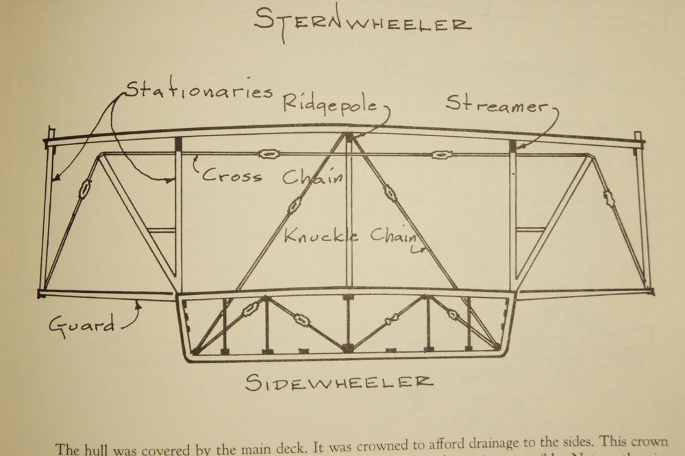
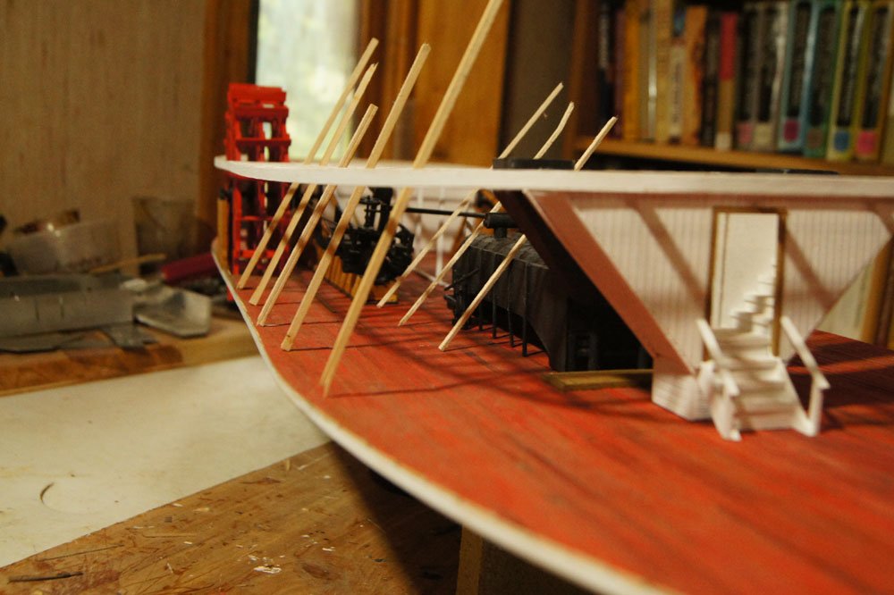
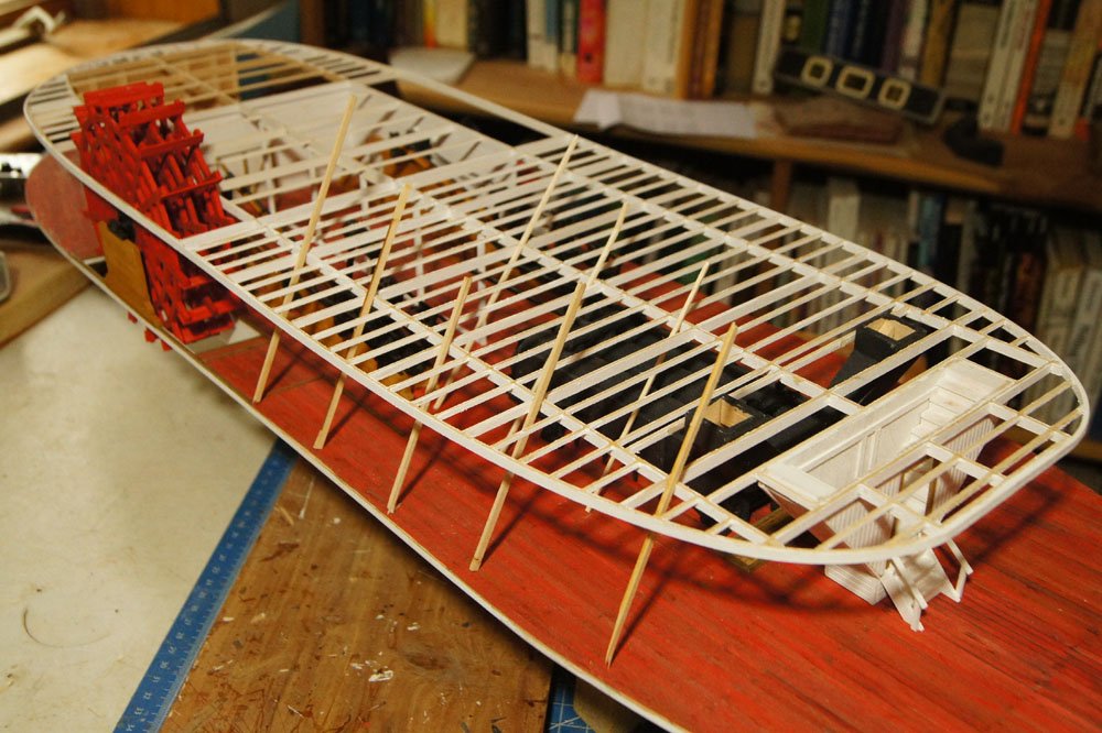
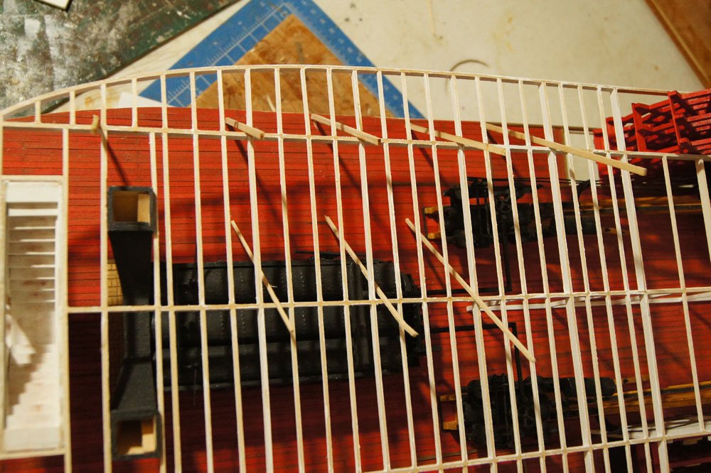
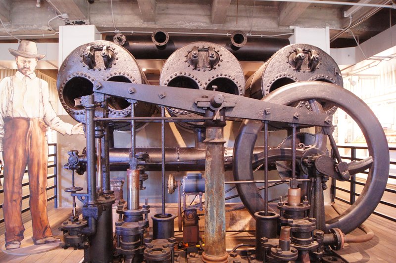
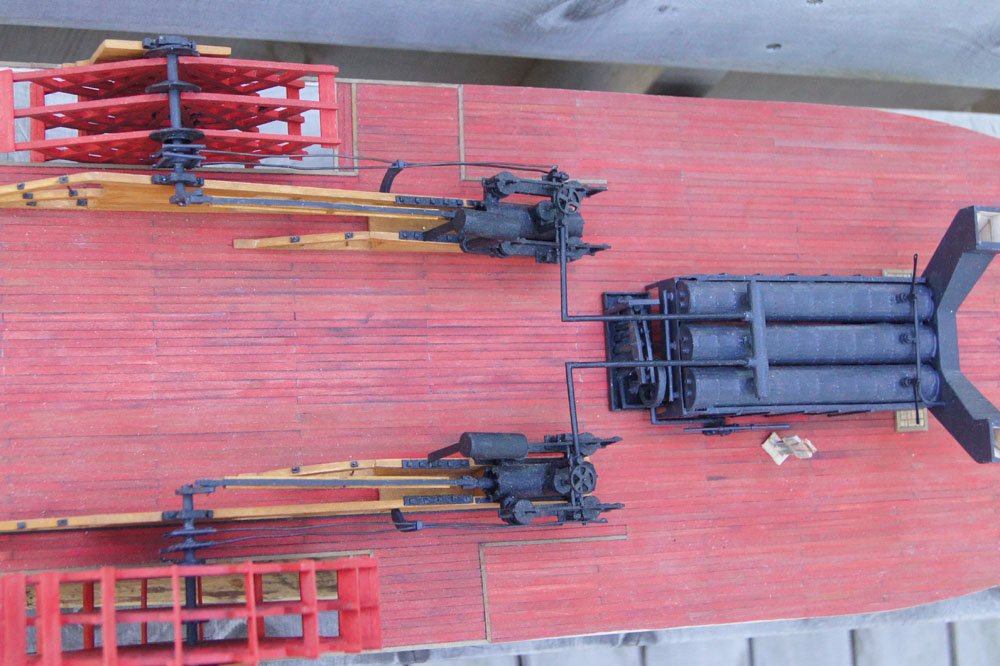
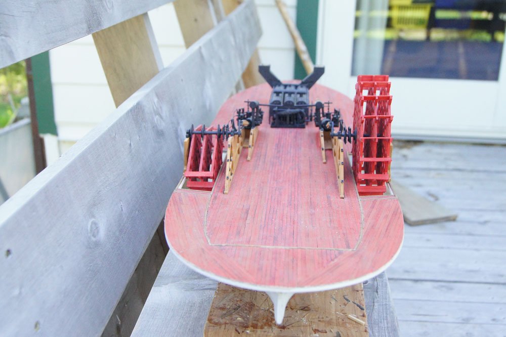
You people are evil, encouraging a second model. It ain't happening until this one is done at the very least. That's not quite right; all the machinery I've built so far can be seen on a fully finished model because the main deck was mostly open to the side. It'll be somewhat obscured, but if I left out any of the detail of what I've built it would look wrong when you gazed on the model from the front or side. Even in the shadows, you need to be able to see the engines, driving arms, etc. The only thing I could skip in a fully finished model is a full wheel, and I already did that on the port side. So the only difference in a "wreck" model would be that you'd see the machinery more clearly without a deck above it. I wish it were otherwise! Moving on, here's the design question I mentioned last time that I need some input on; it relates to the internal bracing. Riverboats used extensive networks of "chains" (actually iron rods with turnbuckles) to keep the hulls from warping. On sternwheelers, the main concern was "hogging", or longitudinal warping, in which the hull tended to flex down at the bow and stern and rise in the middle, especially due to the weight of the engines and wheels right at the stern. Thus the main set of bracing on sternwheelers were hog chains, running longitudinally along the hull and rising above the decks. However, on sidewheelers the biggest concern was sideways warping due to the weight of the wheels hanging off the sides and the wide decks, especially the guards (the deck extensions beyond the main hull). So sidewheelers had a lot of lateral bracing, depicted by Alan Bates like this (I hope it's ok to post this image, I don't know how to explain this without using a Bates drawing). So you see two kinds of visible bracing: the knuckle chains that support the edges of the hull, and the cross chains that support the guards. Pretty straightforward. My question is, how were these spaced along the length of the hull? Although I can find versions of this cross section in various sources, I can't find anyone explaining how many of these were used along the hull's length. Every 10'? Every 20'? How did they interact with major features like the boilers and engines that block their path as shown above? I can't find a diagram or text that deals with this question. Here are some mockups on the Arabia to show what I mean (the boiler deck is just set in place for reference, not attached). Here I've placed scrap wood at the approximate angle of both knuckle and cross chains, at an approximate 10' spacing along the forward hull. But I have no idea if this is right. Note how close the knuckle chains come to the boilers and how the engines essentially block their use. Kurt, Roger, anyone else knowledgeable, I'd love some perspective on the right way to arrange these.
- 599 replies
-
- 8
-
-
- sidewheeler
- arabia
- (and 4 more)
-
Very nice! I'm going to reference that pilot-house wheel when my time comes.
- 133 replies
-
- 3
-
-
- chaperon
- model shipways
- (and 2 more)
-
Steve, you're closer than you know. When I was out on the porch yesterday taking photos for that update, I had my Kindle as well, loaded with the reference photos I was using to get those paired images from the same angle. I set it down on the railing above the model and almost lost my grip; it would have dropped a couple feet straight down onto the port wheel and machinery, bouncing into who knows what else. I really don't know what I would have done in that circumstance.
- 599 replies
-
- 3
-
-
- sidewheeler
- arabia
- (and 4 more)
-
When I showed this update to Mrs. Cathead, she commented "You know, you could just stop there and have a really nice model of the wreck." I have to admit a corner of my mind was intrigued and observed that this would highlight the machinery better (which will mostly be obscured on the final model. It does look pretty cool as a display piece right now. To which she commented "You could just stop there with this one and start over on a new one. Why not both?" That earned her a dirty look.
- 599 replies
-
- 7
-
-
- sidewheeler
- arabia
- (and 4 more)
-
Chris, does this kit include the various bracing cables that supported the chimneys (stacks)? If so, that'll help stabilize them. If not, it'd be a great detail to add for function and appearance.
-
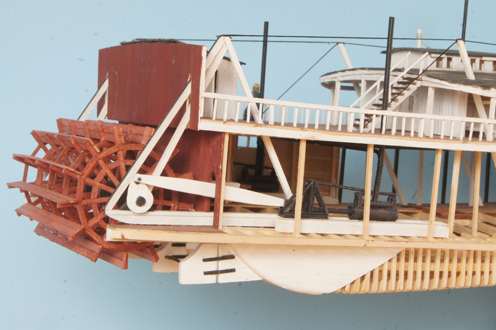
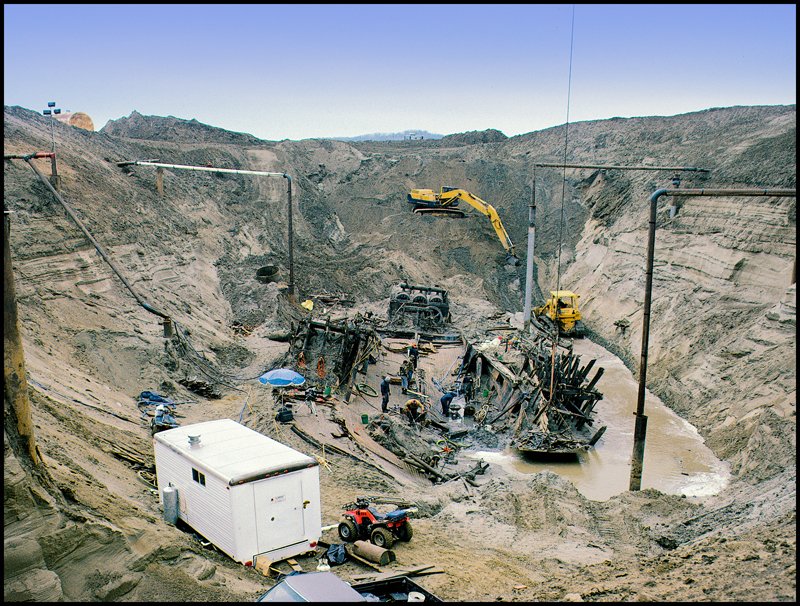
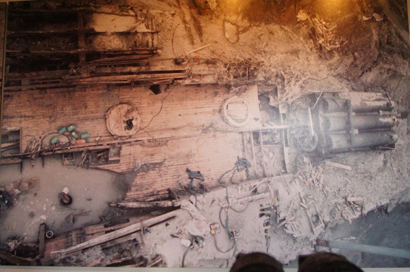
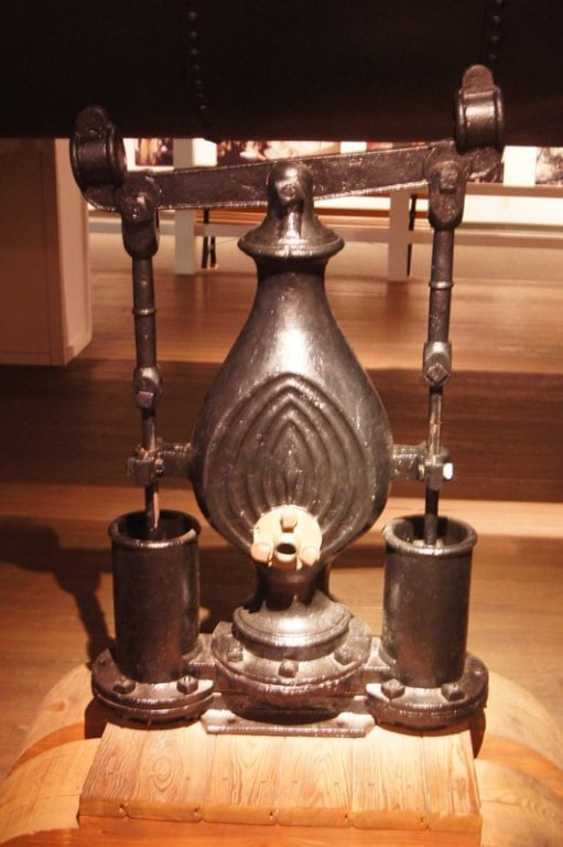
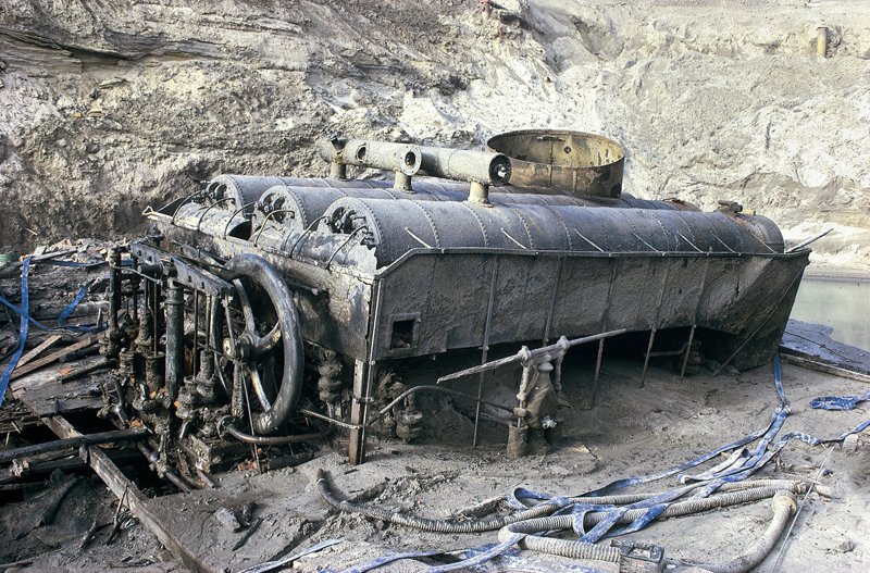
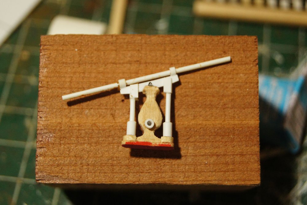
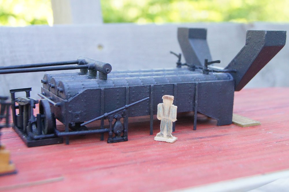
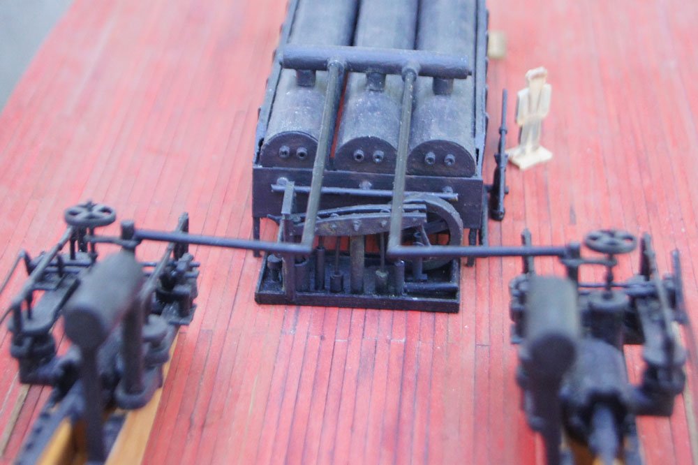
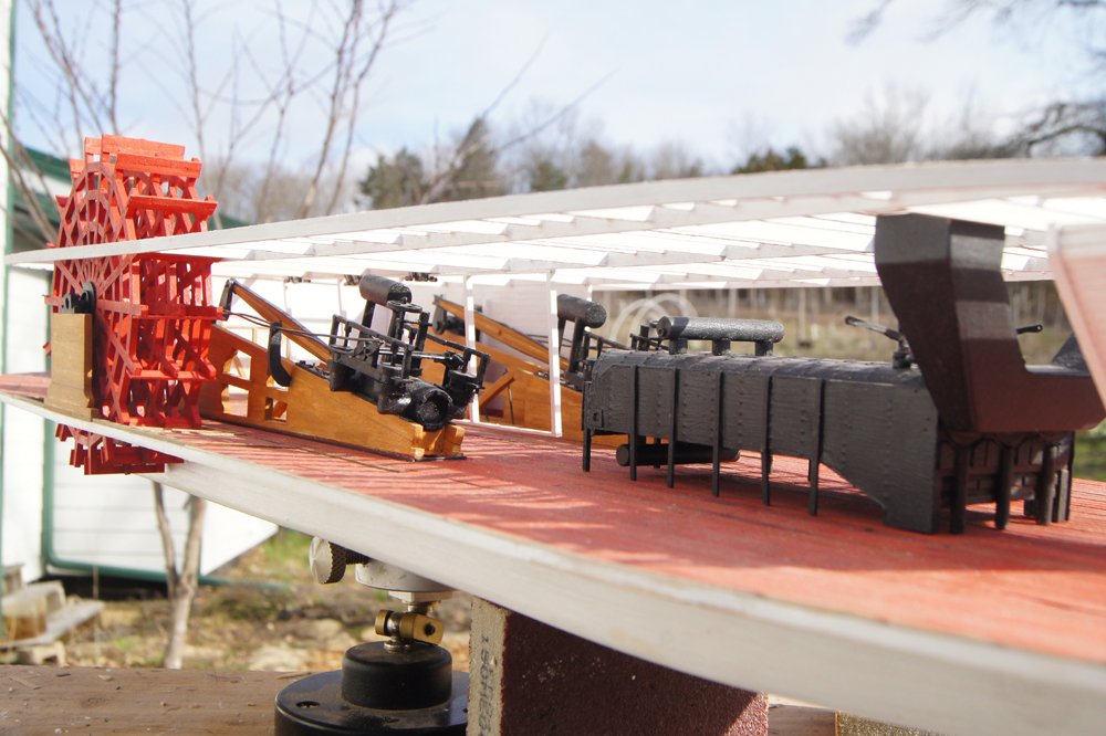
So much for regular updates, but at least I now have meaningful progress to report. I finished the doctor pump (photos further below) as well as the little hand-operated feed pump. The latter sat on the starboard side of the boilers and was used for several purposes including priming the boilers when sufficient steam wasn't raised to operate the larger doctor pump, and any other small-scale water needs. Here's the original (displayed at the museum): And here's my version, first as-built using scrap wood and styrene, then painted. Here's the original in context on the wreck, then a similar view on the model (note that I also made a rough human figure for scale): I clearly cut a few corners in terms of absolute detail, but I think it captures the spirit of this machinery quite nicely and am very happy with how this turned out. At this point, I've permanently installed the boilers and both pumps on the main deck. Here's a closer view of the finished doctor pump with the original: I also installed the steam lines running from the boilers to the engines. Right now these are hanging in space, but they'll be supported from the overhead deck beams once that deck is installed. At this point, the model has reached the limit of what is known for sure. This essentially represents what remained when the wreck was excavated; everything beyond this is conjecture. So I took a few special photos to commemorate this point in the build, pairing them with original wreck photos from similar angles: The next step requires some significant planning and thought, and I'll have a post up asking a few questions about this, but am not ready for that yet. For now, I like thinking of the current model as representing the wreck brought back to life for all of us, rather than the few lucky folks who actually walked her decks in that deep pit. In other news, you can partially blame birds and weather for the slow progress. It's been an unusually nice spring here, leading to many outdoor projects and hikes in the evenings and weekends. This morning we took birding walks before and after breakfast and observed nearly 50 species each time. Between that and various sports it's hard to find time for modeling, but as summer turns uncomfortable I'll be spending more time indoors. This build is just past the 1.5 year mark and I sure hope I can finish this within another year but there's a LOT of fussy detail coming in the upper decks. Also, assuming that anyone reading this is interested in American riverboats, please go check out this new build log of the Chaperon, the only accurate kit available in this genre. Brian's doing a great job with her (some poor advice from me notwithstanding) and it's well worth a look. Thanks for reading.
- 599 replies
-
- 17
-
-
- sidewheeler
- arabia
- (and 4 more)
-
You're kind to imply that I did anything but lead you astray. Rudders look nice. I also left off Arabia's rudder while the build is ongoing; it'll be about the last thing I put on because I'm sure I'll smash it otherwise.
- 133 replies
-
- 2
-
-
- chaperon
- model shipways
- (and 2 more)
-
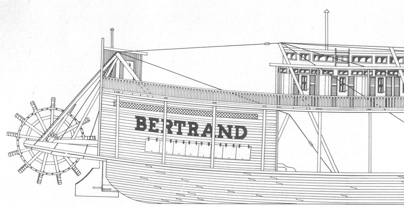
Brian, I owe you (and any other readers) an apology. I was sloppy and rushed when looking up my initial answer and relied too much on personal instinct and a not-thorough-enough review of my books. I'd found the Bates drawing on p. 38 which shows a Bertrand-style (skeg) rudder, stating that it was favored for many years; the next page shows a Chaperon-style (balanced) rudder in relation to towboats. As I was flipping backward through the book, I stopped there. If I'd gone further back, I'd have found the drawings Kurt shows above, as well as one on p. 37, and text clarifying the evolution of these designs. My apologies for getting ahead of myself and providing incorrect information. I hadn't thought about sternwheeler rudders in a few years and got ahead of myself. Also, looking up the rudder section in Louis C. Hunter's tome gives this passage on balance rudders: The official book on Bertrand makes a big deal out of her skeg rudders being state-of-the-art for her time, and I mistakenly projected that forward in time to a period about which I know less (the late 1800s). But it's now clear that this design gave way to balance rudders by Chaperon's time. Again, my apologies for getting ahead of myself. I should know to wait for Kurt to chime in before adding my own thoughts, especially on this kit/craft.
- 133 replies
-
- 3
-
-
- chaperon
- model shipways
- (and 2 more)
-
Brian, for what it's worth, Arabia was built in 1853 and Chaperon in 1884, which spans a pretty significant proportion of the entire steamboat era of US western rivers. I reviewed my various reference books last night and none specifically discuss rudder construction (as opposed to overall design). Also, looking more closely at your post and the kit instructions, it's interesting to me that the kit seems to have two rudders, both of which are entirely one piece pivoting on a single axis. I.e., the part that curves forward under the hull pivots along with the part that extends aft. Am I seeing that correctly? If so, that's really different than how it was done on earlier vessels that I'm more familiar with, like Bertrand, and makes me suspicious that the kit is cheating there although I can't be sure. As far as I know, most sternwheeler rudders were hinged from permanent wings attached to the hull running forward, not from pivoting rods extending up into the hull as the kit seems to have. Here's two images from my Bertrand build, first from the archeological reconstruction and second from my model: The major reason for this was protection; if those forward projections actually rotated on a vertical axis, the rudders would be torn off by debris and/or water pressure in no time. Fixed to the hull, they actually help protect the rudders and provide a much more solid mounting platform. Also, many later boats had two sets of paired rudders (four total), in which the two inboard ones were actually attached to tillers and the two outboard ones were slaved (connected) to them. I have no idea if the real Chaperon used this design, but Bertrand was an early adopter of this design when it was built in 1864 (9 years after Arabia). If you want more detail on this, I can send or post some more images from my collection and resources.


- 133 replies
-
- 4
-
-
- chaperon
- model shipways
- (and 2 more)
-
Just now ran across your build, so glad to see another Chaperon underway. Your work looks great so far. The deck extension is highly true to the spirit of a real riverboat; they were hard-working vessels that were always getting dinged up, repaired, adjusted, and altered as circumstances warranted. As for the rudder question, you can find more photos of Arabia's rudder in the design thread I wrote up for my current project scratchbuilding her. Her rudder was all-wood, held together by several iron rods threaded through the assembly and the wood sheathing nailed on. I believe Bertrand's were done the same way, one of the few other steamboats to have been excavated. These were both decades prior to Chaperon, and I can't say for sure that's how it was done on the latter. Western river boats tended to have thick, strong rudders that could withstand being knocked about by snags and other debris, and the reason for all-timber construction was easy repair. On a remote river where repair facilities are few and far between and damage fairly common, a rudder made primarily of wood with a minimum of metal was much easier to repair/replace than one with lots of special iron banding and other metalwork. Arabia's could be rebuilt with a tree, an ax, and a few iron rods. You're certainly right about dirty hands and white paints, I've had the same problem on all my riverboats. Although, if you manage it right, some natural dirt and grime adds to the realism, especially for a coal-powered vessel like yours. Keep up the great work!
- 133 replies
-
- 2
-
-
- chaperon
- model shipways
- (and 2 more)
-
Most lovely work, sir. As the Bard wrote,
- 48 replies
-
- 7
-
-
- queen anne barge
- Syren Ship Model Company
- (and 1 more)
-
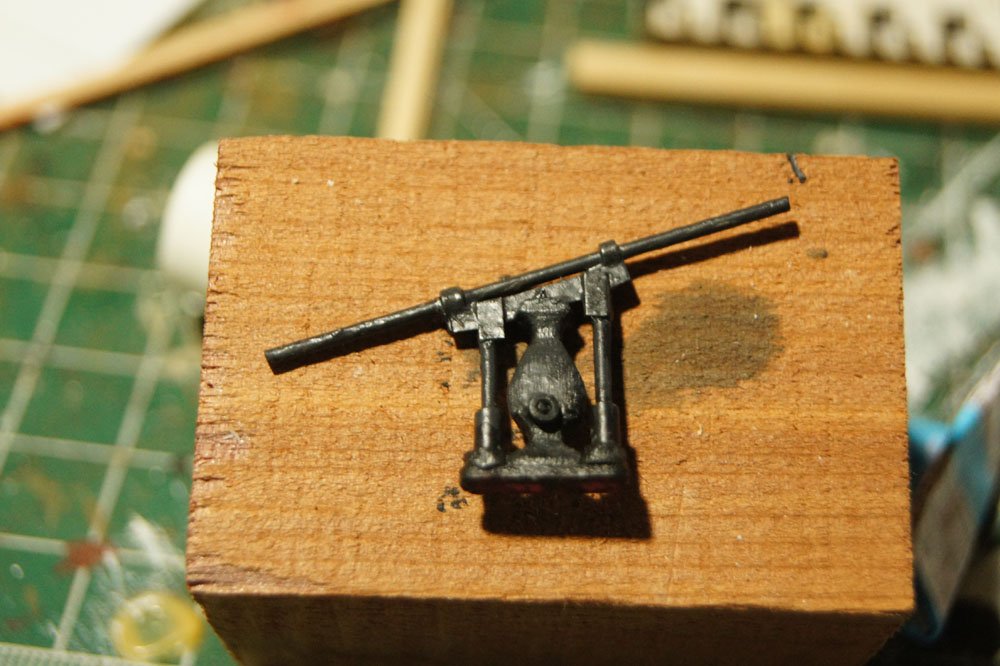
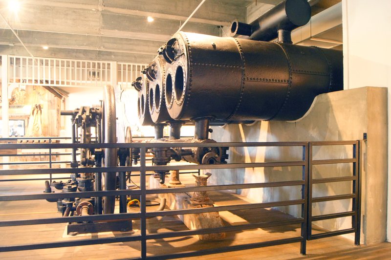
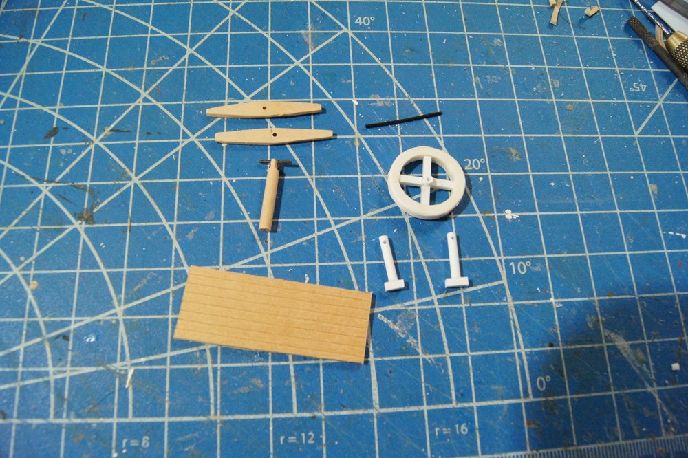
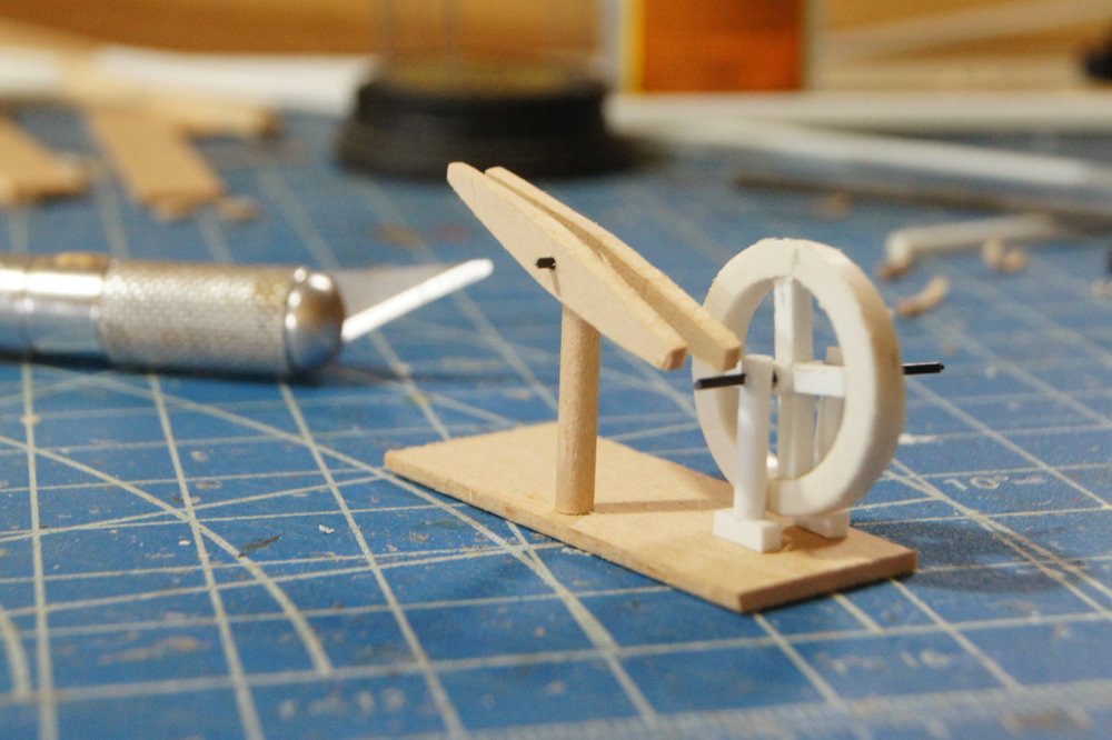
The next mini-project involves the two main pumps next to the boilers. These have to be finished and installed before I attach the next deck. The big on is the "doctor" pump, which draws river water to feed the boilers and for any other major water needs. The odd name comes, supposedly, from the fact that its invention cured a variety of problems in riverboat boiler/engine development. Here's a reminder of what Arabia's doctor pump looked like: As with the other machinery, I knew that (a) I wouldn't be able to craft a perfect replica and (b) it wouldn't be fully visible anyway, so my goal was to craft a reasonable representation of the general idea. There's a lot of stuff going on with this pump, but after some rummaging and head-scratching, my scrap box and other sources around the house turned up some good-enough material. I started by making the main flywheel, for which I used a ring cut from a length of PVC pipe left over in our barn. It's not quite to scale but it was the closest ring-like item I could come up with. I then carefully made the central axle and spokes, not trying to mimic the beautiful swirled shape of the original because I felt it would be beyond me. I used a hollow section of styrene tubing for the central part so I could string this on a piece of wire, making it easier to assemble the whole thing later on. The supporting stanchions are more of the same styrene, drilled to accept the wire "axle". The parallel pump "handles" (not sure just what those are actually called) I shaped from two pieces of wood, then filed and drilled a dowel to hold another piece of wire that would, again, make these easier to mount. So here they are loosely test-fit on a base. I think with some sanding, painting, and finishing detail, they'll blend into a fairly decent representation. This will only ever be seen from the side through parts of the superstructure, in partial shadow. Not sure if I'll get any farther this weekend, got a variety of commitments coming up, but I'd like to get back to more regular updates so figured I'd show this much.
- 599 replies
-
- 14
-
-
- sidewheeler
- arabia
- (and 4 more)
-
Thanks, all. John, Mrs. Cathead and I are very much on the bird-watcher end of the spectrum. We have only basic camera equipment that we rarely use to try to photograph birds (more often wildflowers and things that don't move). We could easily get sucked deeper into photography, Mrs. Cathead in particular, but we've never really dedicated the budget to it and are generally happy to appreciate others' efforts in that regard. In a parallel way, though, Mrs. Cathead really enjoys recording and analyzing bird vocalizations and has been building up a nice library of "audio photographs" if you think about it that way. We are not twitchers in that we don't care all that much about obsessively building up a life species list, and we're far more interested in observing, studying, and appreciate birds and other flora fauna than we are about listing them. We're reasonably skilled birders and are quite active in our local Audubon Society, editing and producing its newsletter, leading field trips, giving programs, etc. In fact, we're giving an "Introduction to bird vocalization" talk in a few weeks over in Kansas City (a few hours from our rural location). We consider ourselves serious amateur naturalists who are interested in ecology as a whole over any given aspect of it (i.e., we pay attention to wildflowers, mushrooms, insects, native plants, mosses, etc.). We keep a loose life list as it's interesting to know what we've seen, but we consider birding just one aspect of our overall interest in ecology rather than an end unto itself.
- 599 replies
-
- 5
-
-
- sidewheeler
- arabia
- (and 4 more)
-
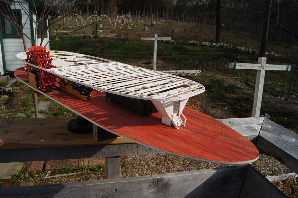
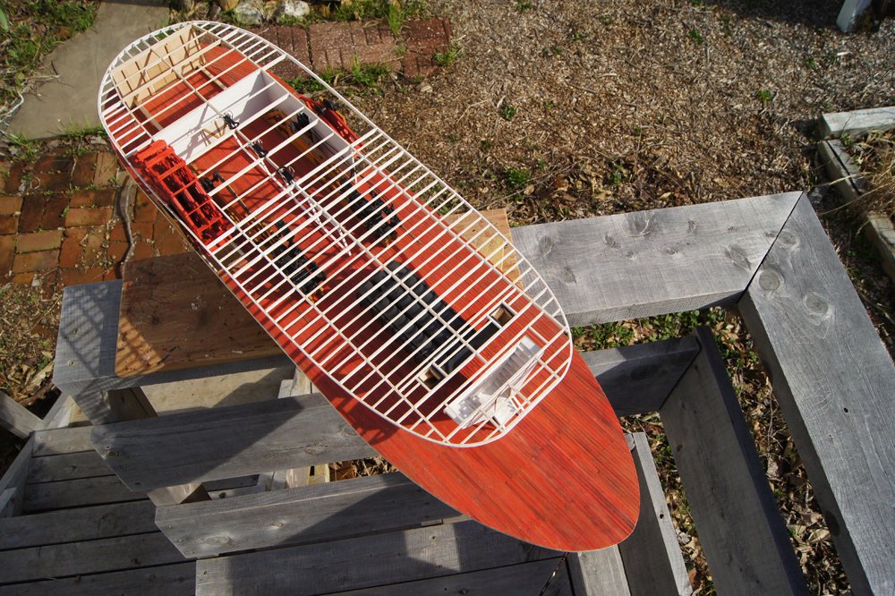
I've quietly been working on developing the main deck superstructure in relation to the boiler deck. The downside to pre-building the latter is making sure everything fits just right when it's finally attached to the main deck. I've been doing a lot of measuring and test-fitting. Below are a few images of the current state. This is all test-fitted, not attached permanently (except the wheels and engines), but it gives a nice hint of where the model is going. In the last image, you can see proof that this is a test fit, because the internal stanchions down the center-line are clamped to the boiler deck but don't reach the main deck (and are at a cock-eyed angle)! This is because the former was built flat but will flex with the slight sheer of the main deck once it's installed for good. Before I attach all this permanently, I need to be sure I've got any details I want installed on the main deck. For example, I haven't built the various ancillary pumps that go with the boilers. I will also need to install some of the piping connecting the boilers with the engines. The current plan is to deal with that stuff, take a deep breath and attach the boiler deck, then fill in the rest of the superstructure between the two decks. Progress has been and will continue to be slow. With spring here (compare the outdoors conditions in my last post, three weeks ago, with these) and there's a lot of competition for my non-work time between needs (orchard pruning, final firewood cutting and splitting, fence repair, etc.) and pleasure (spring birding, seasons underway for American soccer & baseball). Thanks for reading, and for patience with my slow progress and intermittent updates.
- 599 replies
-
- 20
-
-
- sidewheeler
- arabia
- (and 4 more)