dafi
-
Posts
2,434 -
Joined
-
Last visited


Recent Profile Visitors
8,827 profile views


-
 dafi reacted to a post in a topic:
Deck planking
dafi reacted to a post in a topic:
Deck planking
-
dafi reacted to a post in a topic:
Deck planking
-
Russ2025 reacted to a post in a topic:
USS Constitution by dafi - Revell - PLASTIC - To Constitution and beyond ...
-
NW Ship Builder reacted to a post in a topic:
USS Constitution by dafi - Revell - PLASTIC - To Constitution and beyond ...
-
rybakov reacted to a post in a topic:
USS Constitution by dafi - Revell - PLASTIC - To Constitution and beyond ...
-
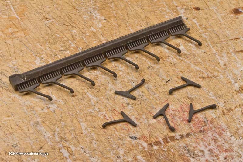
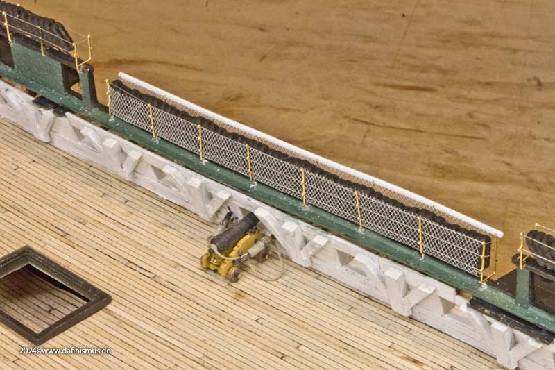
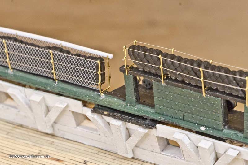
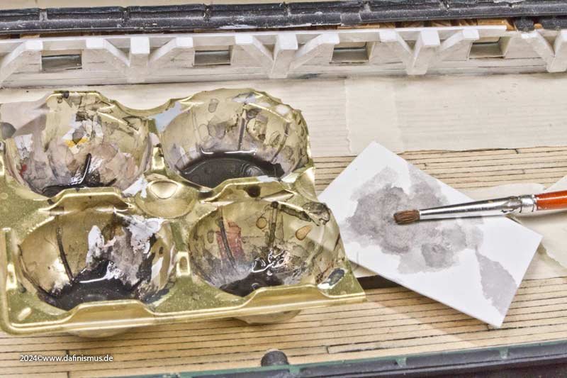
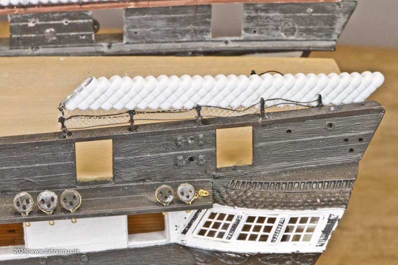
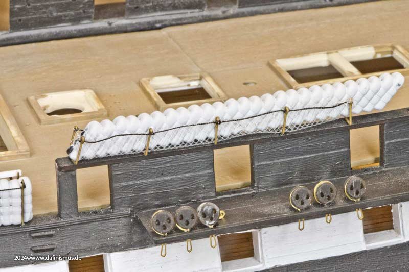
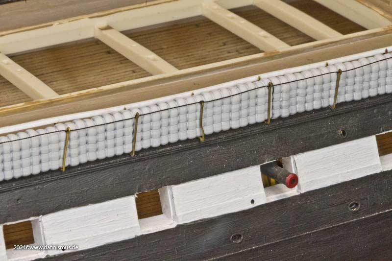
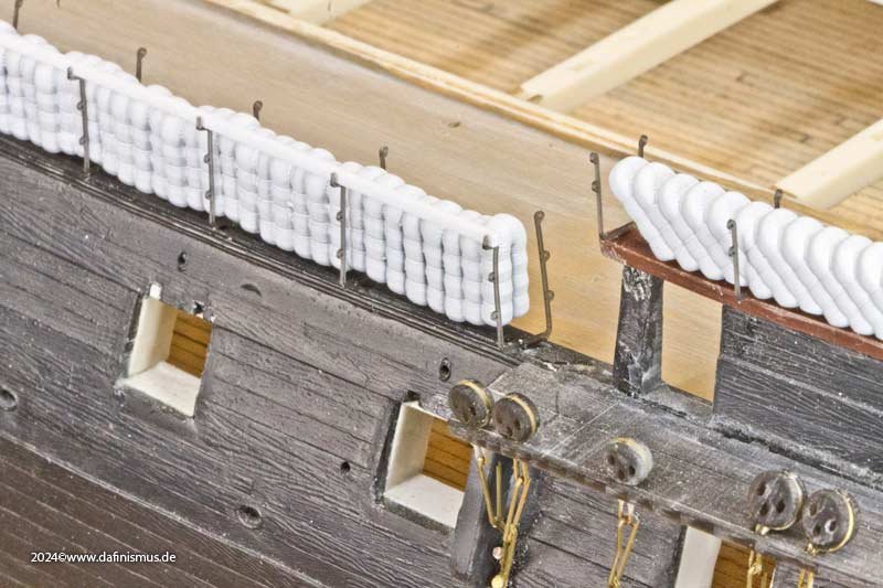
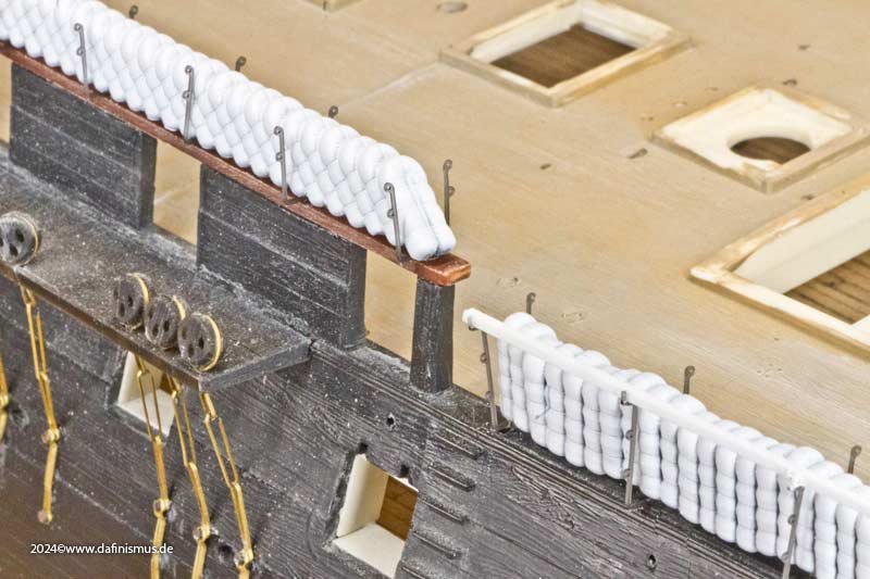
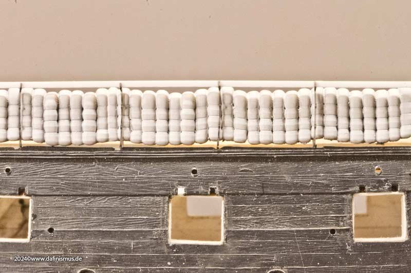
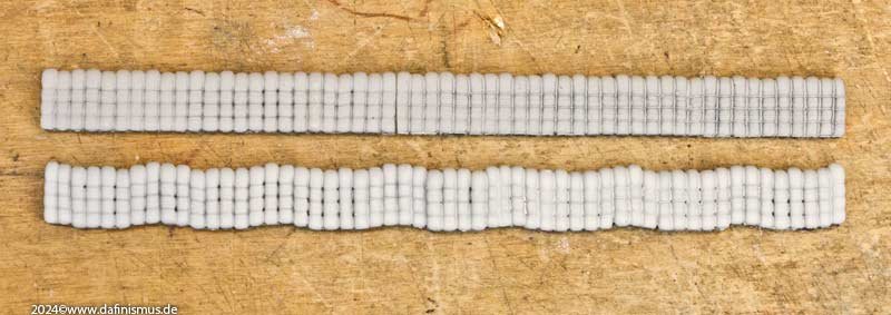
 And then it was time to paint those hammocks http://www.shipmodels.info/mws_forum/images/smilies/icon_smile.gif Now with the build on hammock net holders I was able to adjust the rhythm of the cranes to the wave of the hammocks. Now gravity could take it´s toll properly, resulting in some more convincing sagging in the print data. After printing I still fine-tuned the new print by hand, so that the hammocks would fit nicely into the holders without any unlogical gaps to the mainrail. The first step in painting was to apply a white spray primer and then brush on a tinted white to create a uniform base colour. As described above, a lot of effort went into giving the mats a natural disorder so that they would not look like sterile printed parts. Therefore the painting must, of course, support this step. In the next step, each mat was given its own individual colouring. The paint was mixed fresh on the wet palette and the colour nuances were distributed evenly. In times before the advent of Tide, when there was not enough fresh water to wash with soap, and with plenty of tar and other sources of dirt, I assume that the colour was more of a greyish natural tone, with each roll having a different colour, just like the ropes too. In the final step, I used a few washes of ink to highlight the structure again and restore depth and life to the rolls. It looks more massive in the close-up than it does to the naked eye. In addition, there will be the hammock netting in front of them, which also contribute to the colour shades becoming less nuanced. Hope you enjoy 🙂 XXXDAn
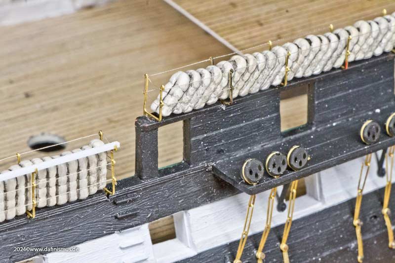
- 64 replies
-
- 3
-
-
- Revell
- Constitution
- (and 1 more)
-
 CODY reacted to a post in a topic:
USS Constitution by dafi - Revell - PLASTIC - To Constitution and beyond ...
CODY reacted to a post in a topic:
USS Constitution by dafi - Revell - PLASTIC - To Constitution and beyond ...
-
Marcus.K. reacted to a post in a topic:
USS Constitution by dafi - Revell - PLASTIC - To Constitution and beyond ...
-
Marcus.K. reacted to a post in a topic:
USS Constitution by dafi - Revell - PLASTIC - To Constitution and beyond ...
-
schooner reacted to a post in a topic:
USS Constitution by dafi - Revell - PLASTIC - To Constitution and beyond ...
-
rybakov reacted to a post in a topic:
USS Constitution by dafi - Revell - PLASTIC - To Constitution and beyond ...
-
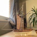
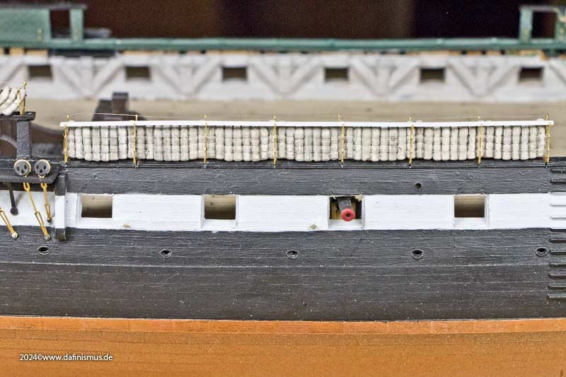
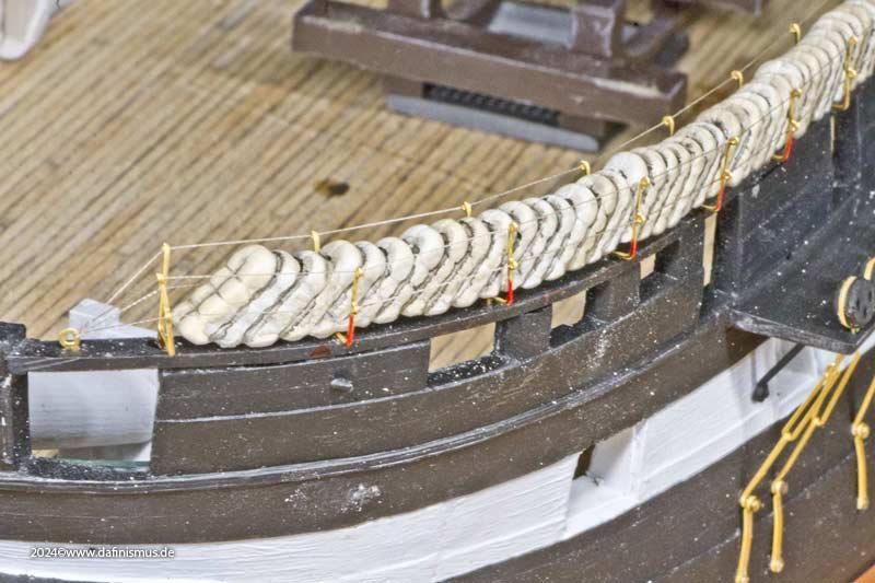
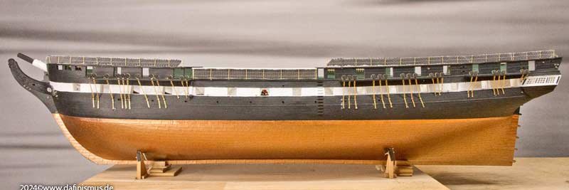
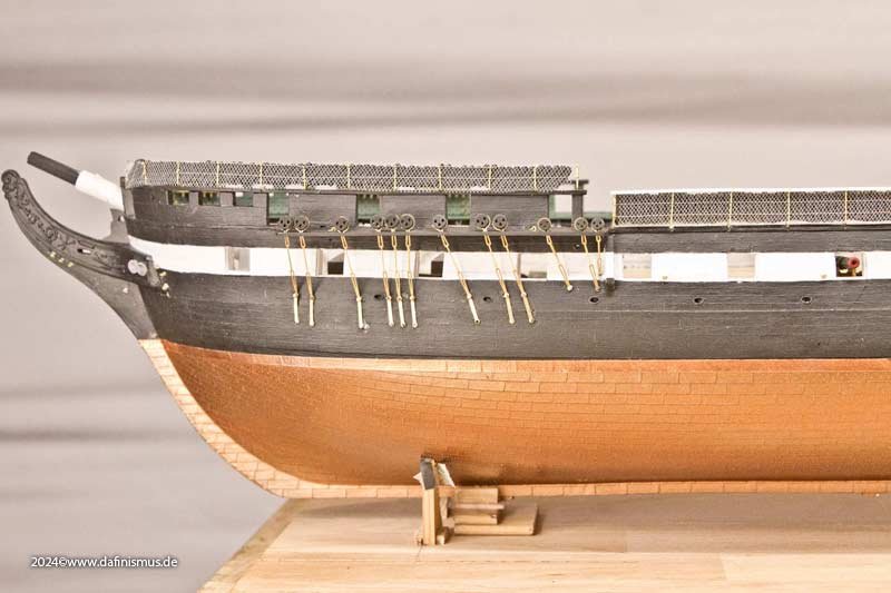
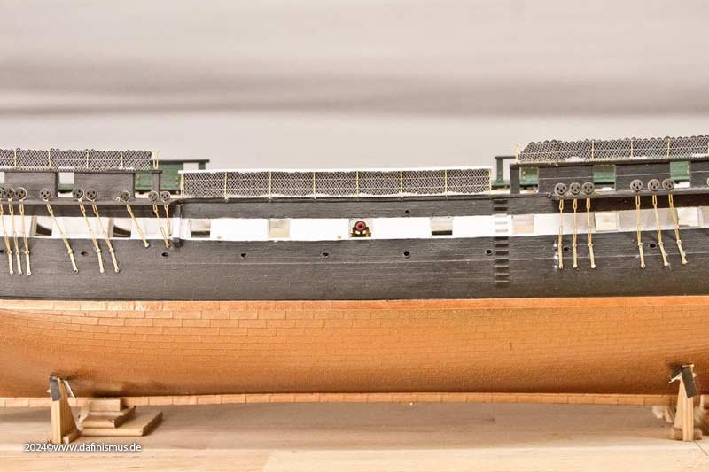
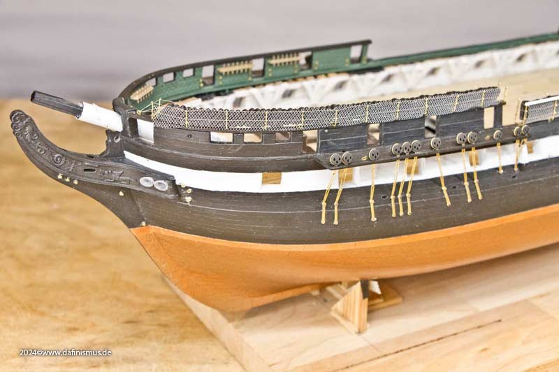
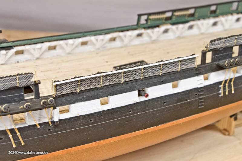
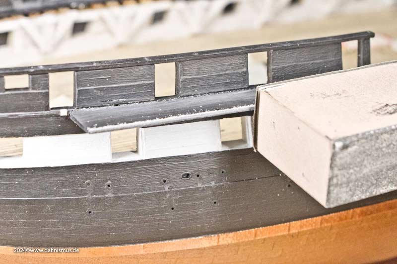
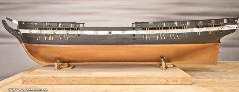
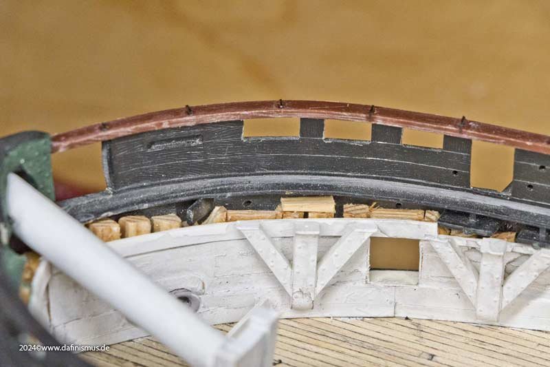
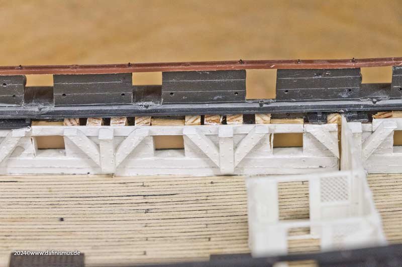
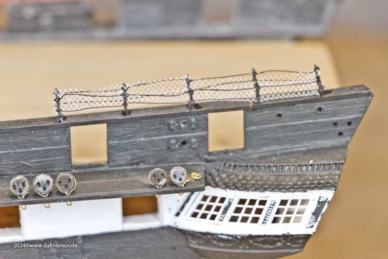
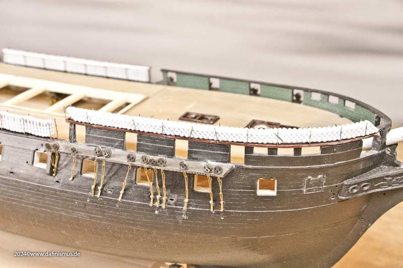
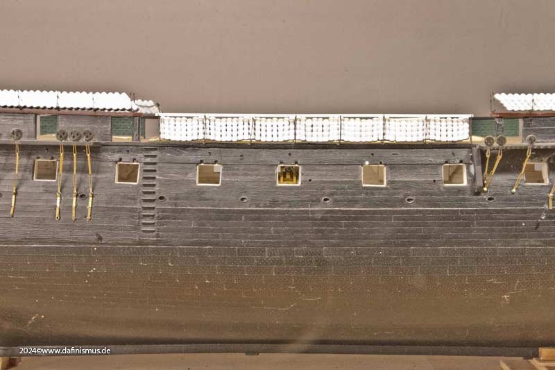
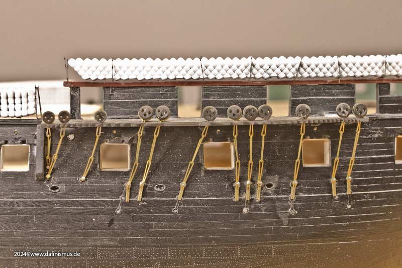
At some point, I noticed on the model that the channel boards have no supports. The contemporary models of the constitution and the drawings also omit them, but could this have been one of the details that are not shown as they are too unimportant? Just as a point of discussion I retrofitted them. Next, I put in some dummy hammock nets. Just to see how they look. The real ones will come once the weather deck is installed. They're just too delicate. But it was worth it, because the side view has changed again. XXXDAn
- 64 replies
-
- 4
-
-
-
- Revell
- Constitution
- (and 1 more)
-
CODY reacted to a post in a topic:
USS Constitution by dafi - Revell - PLASTIC - To Constitution and beyond ...
-
Force9 reacted to a post in a topic:
USS Constitution by dafi - Revell - PLASTIC - To Constitution and beyond ...
-
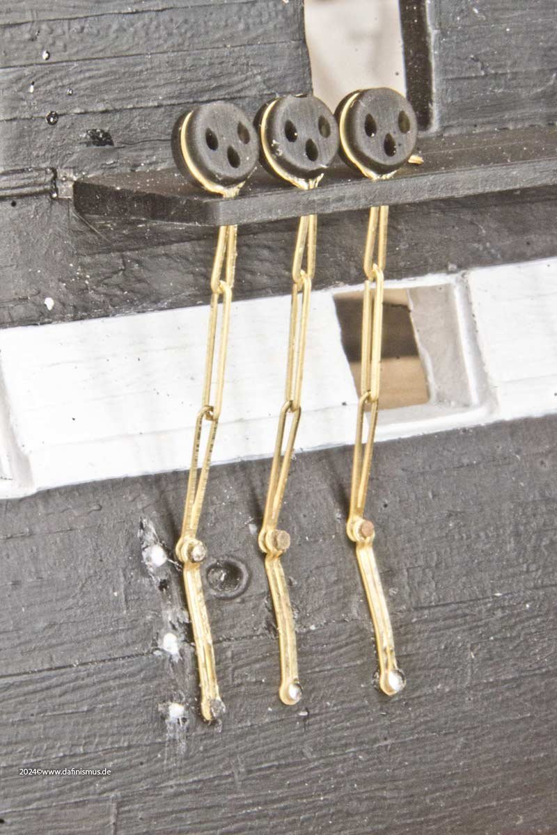
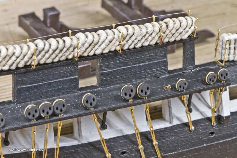
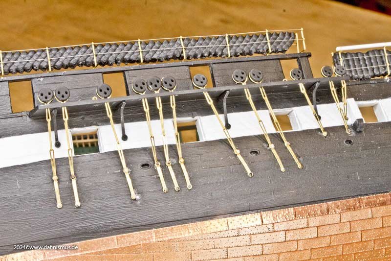
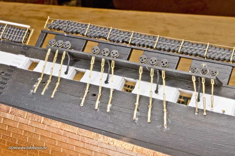
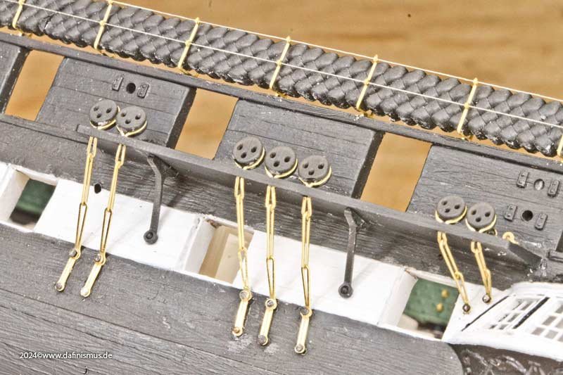
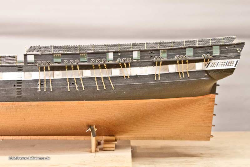
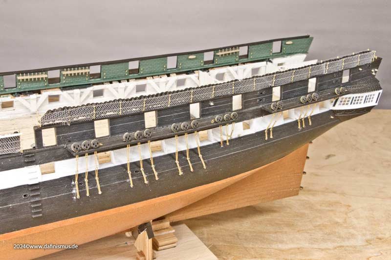
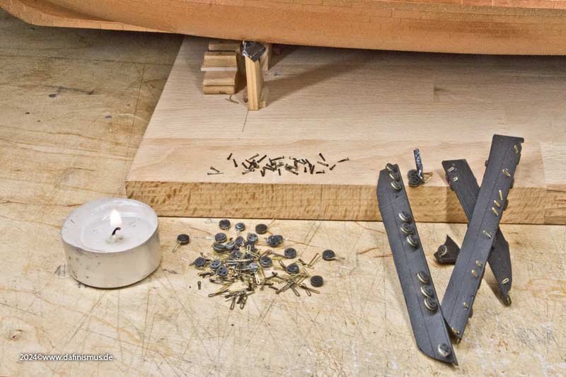
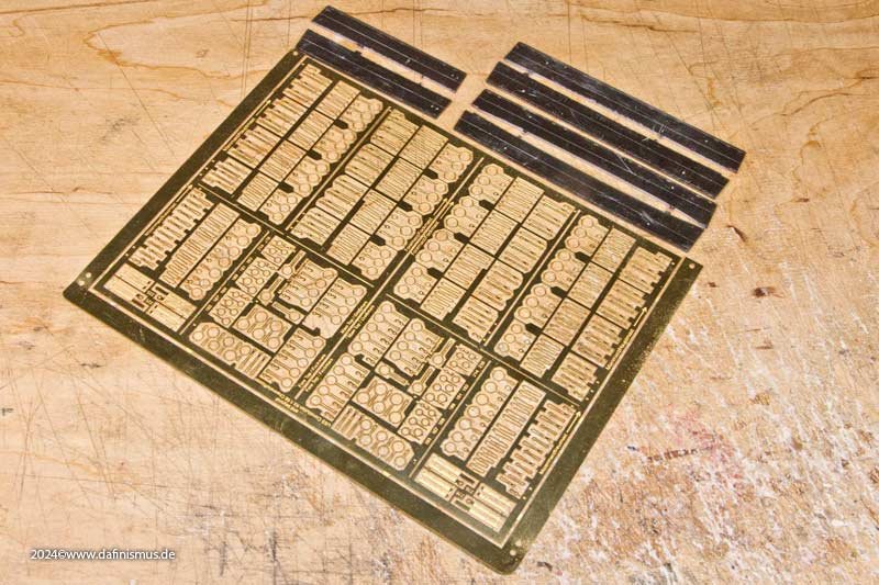
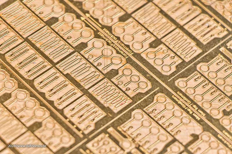
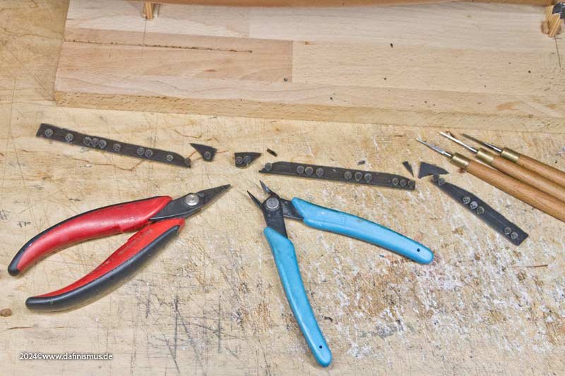
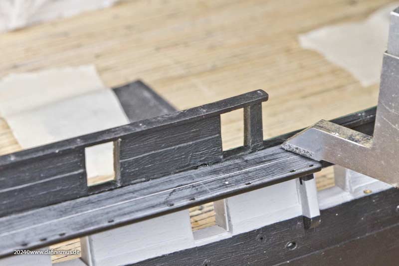
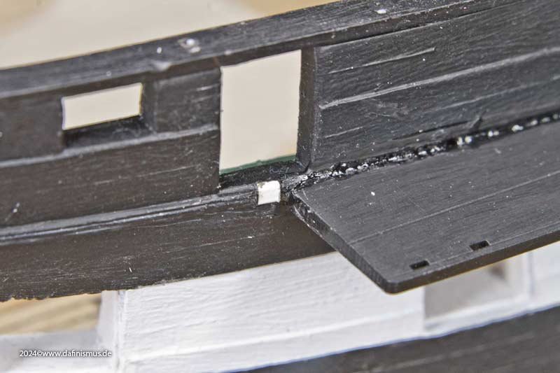
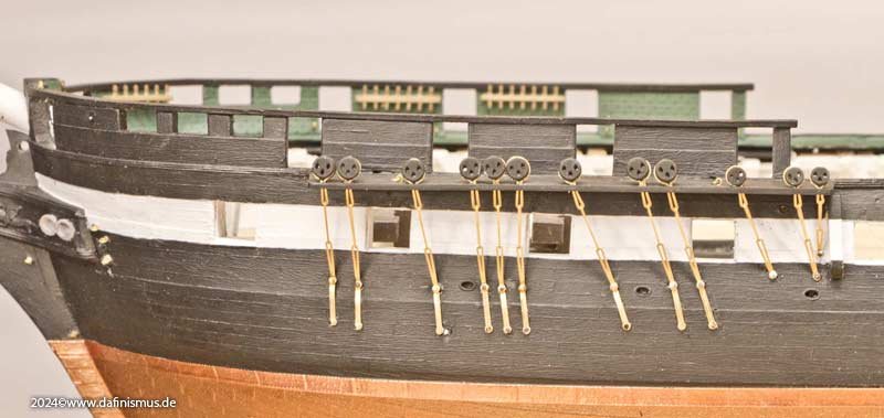
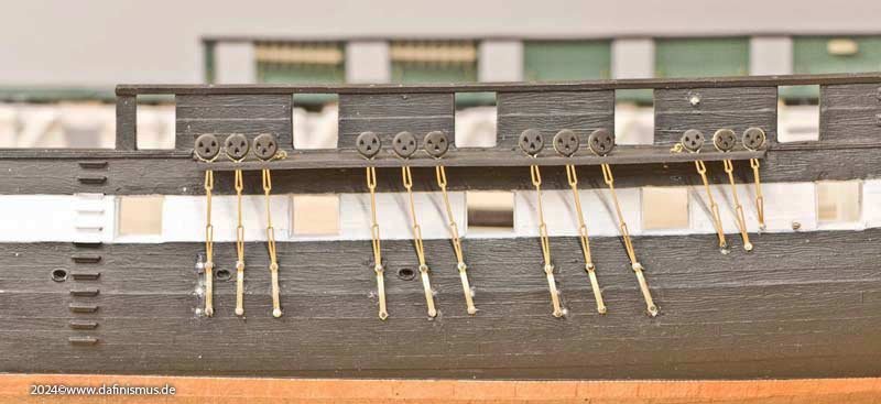
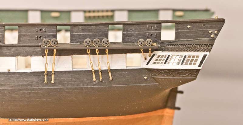
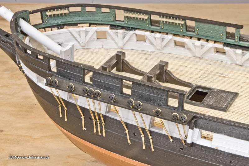
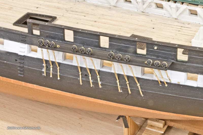
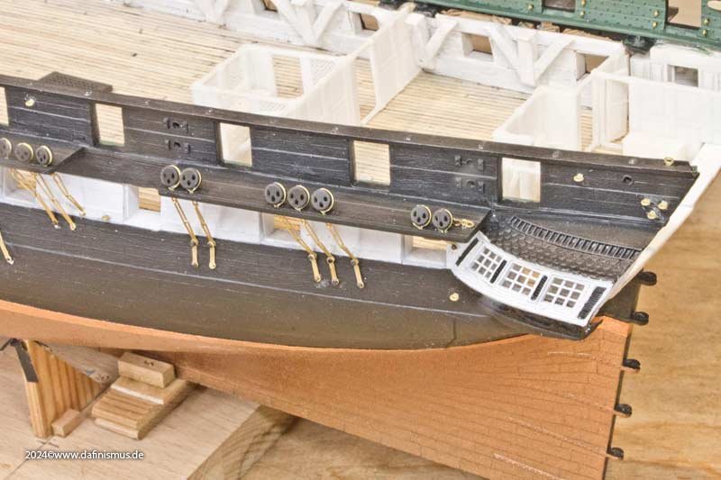
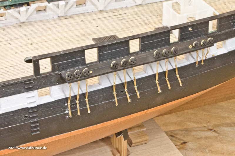
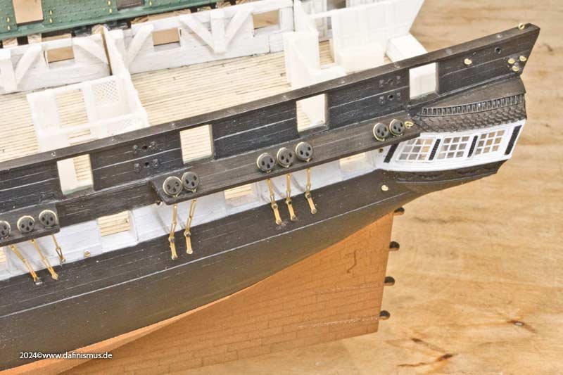
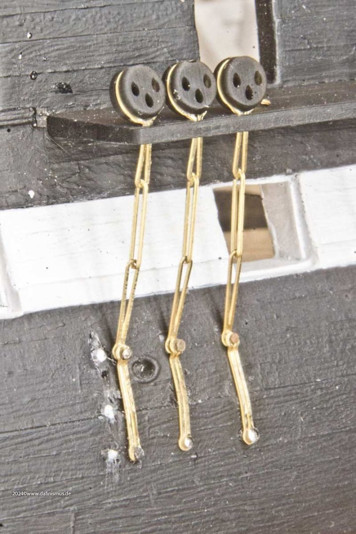
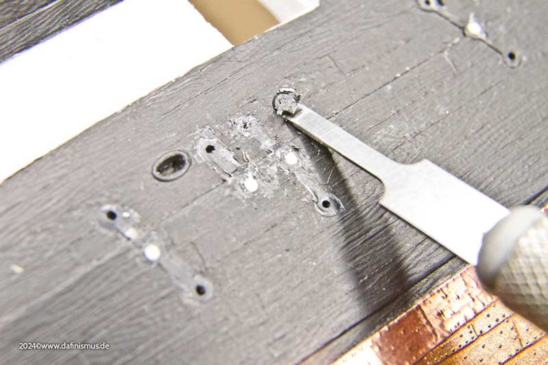
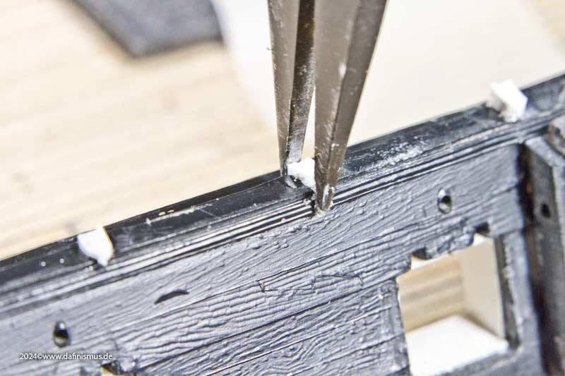
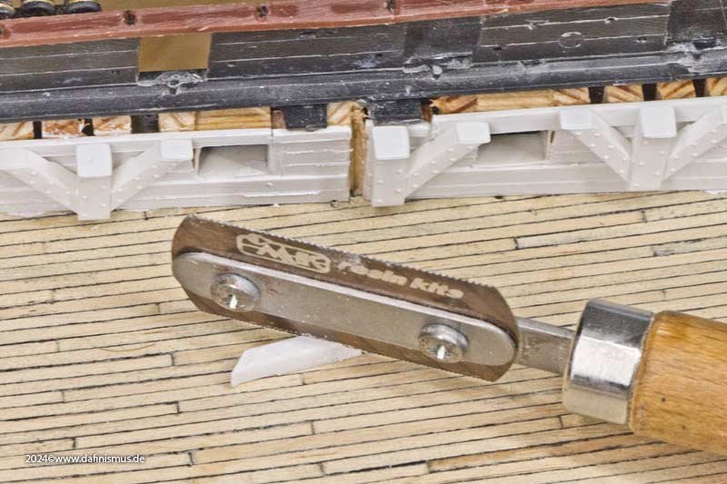
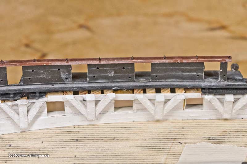
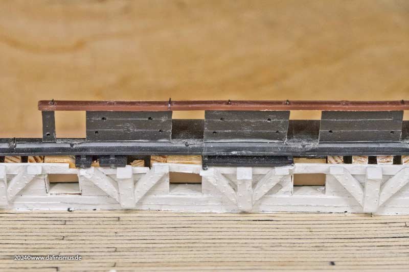
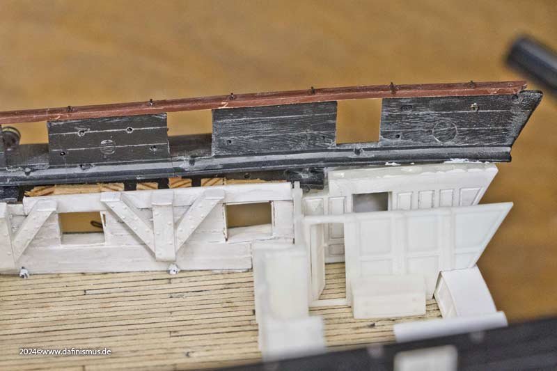
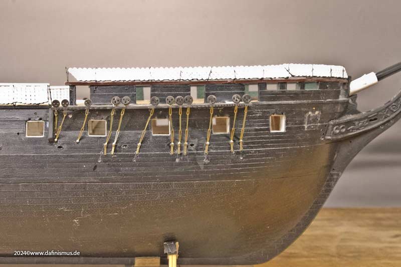
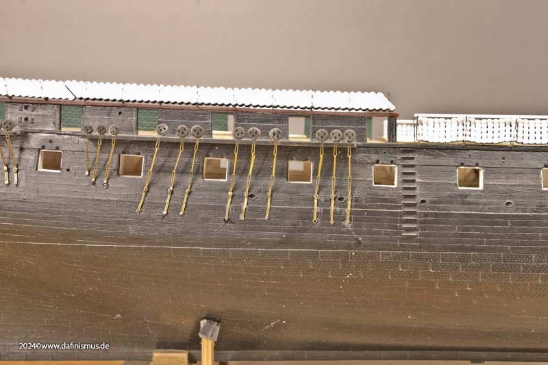
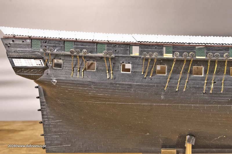
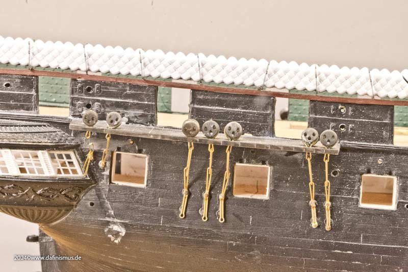
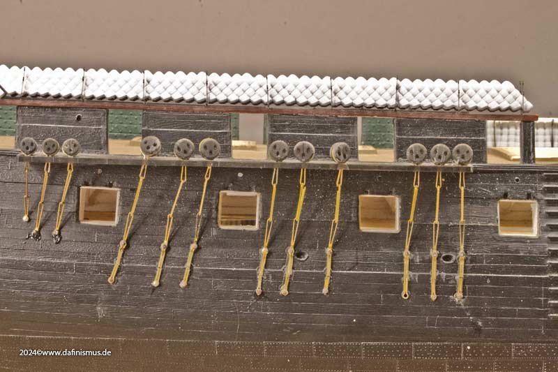
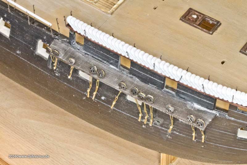
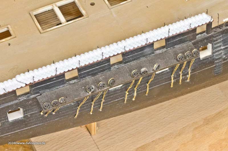
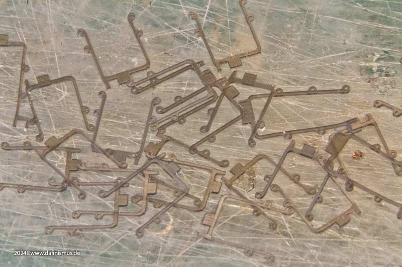
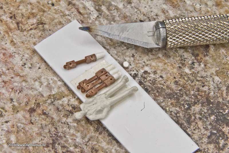
And now came the part I was most looking forward to: things immediately got exciting again, the old test channels had to come down! And just like centuries ago, the fire separated the iron parts from the rest and cleaned them of adhesive residue. Me, lazy sod that I am, wanted to save the needle head bolts, which always takes a while to get done. And there they were, ready and waiting, the new channel boards and irons 🙂 It took a lot of effort to clean up the glue residues on the slots for the channel boards, as the model had already had about five previous versions glued on, including the original kit´s channels :-O. Once everything was clean and fitted, the new boards were put in place and a horizontal stop helped with the alignment ... ... and, although only minimally visible, the print-induced steps on the edge were sanded down... ... and the inner edges and connections were cleaned up ... ... and paint cleared from the holes for the irons with a fretsaw blade. And then it was time to start cutting out the etched iron parts, bending the eyes, fitting the dead eyes, adjusting the length of the links and bolting them to the side wall. Just like in the big original. The result was quite impressive; the new parts fit perfectly. In some places, I deliberately left the white stubs in place to show that the original holes in the kit were sometimes not ideally placed. It turned out quite satisfying, here's a close-up, just because we can http://www.shipmodels.info/mws_forum/images/smilies/icon_wink.gif And next up are the hammock net holders. XXXDAn

- 64 replies
-
- 6
-
-
-
- Revell
- Constitution
- (and 1 more)
-
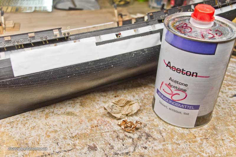
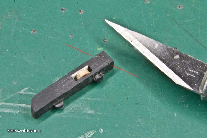
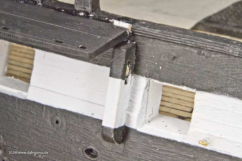
But first, it was time to tidy up. The kit had suffered greatly, having been assembled quickly under time pressure, pushed from one place to another, and generally not treated like a beloved model child. I'm sorry about that. Really. Reall-really … First, the old copper test had to be removed. The stuff sticks like hell. Unfortunately, it had been primed underneath – something I don't normally do – and even a lot of isopropanol couldn't prevent the paint from coming off in places. But I was able to smooth it out inconspicuously. But that's part of the demolition process, which fits in with dafi's whole artistic concept 😉 Then the self-printed hammock crane holder dummies flew through the workroom in a high arc and the lower links of the preventer chains that had been injection moulded onto the hull were scraped off with a scalpel and excess holes were closed with plugs. For the huge gaps in the gangway in the kit forseen for the kit´s holders, there were matching polystyrene plugs, which were softened with plenty of styrene glue and then pressed into the gap with pliers. The bitts on the side of the ship for the main tack were also sanded down, sawn with a fretsaw, fitted with a roller and shortened so that it would fit under the new channel boards. The interior also needed a lot of work. Spray and glue the knees. Where there are bulkheads, I cut off the arms for simplicity's sake. Then, as usual, I used some diluted ink to emphasise the corners and screw heads. And then it looked much more homely. XXXDAn
- 64 replies
-
- 5
-
-
- Revell
- Constitution
- (and 1 more)
-
dafi reacted to a post in a topic:
HMS Victory by dafi - Heller - PLASTIC - To Victory and beyond ...
-
dafi reacted to a post in a topic:
HMS Victory by dafi - Heller - PLASTIC - To Victory and beyond ...
-
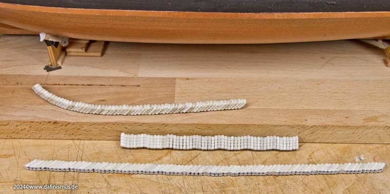
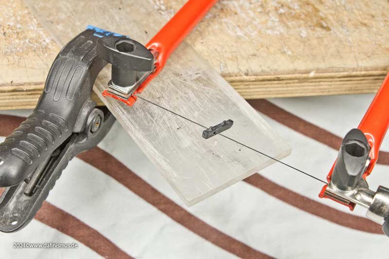
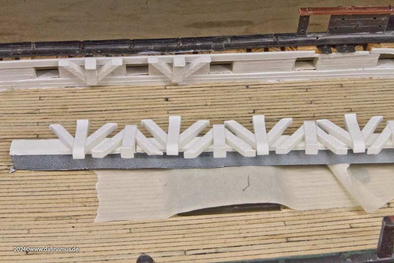
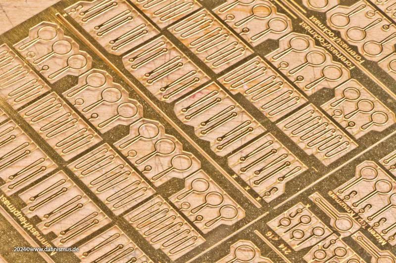
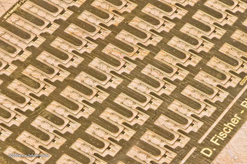
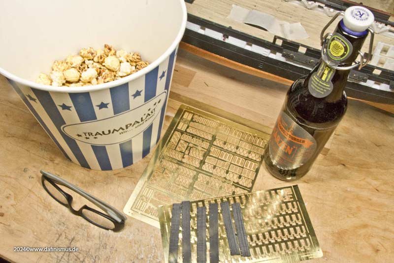
Before I get to the current events, here is a brief summary of what else has been happening here. At the beginning of last year, I started working on the hammock holders and channels. This is how Revell envisions it. You can't even fit hammocks in there... ... ... so I hijacked some of the holders from my Vic. Still too small. So I drew new etched parts for the holders, and the nice thing is that you can try them out right away in print – and notice during assembly that print is too weak for such parts. But I was able to clarify that the parts really are the right size. And this is what it looks like when installed. I had rolled lots of virtual hammocks to match, so I could estimate the result. Here you can see that the mats have been given a good dose of unshipshapeness. This serves to prevent a sterile-looking impression. I had already used the wave effect, where gravity pulls between the holders on the mats, on my hand-rolled mats on the other models, and it made the result look much more realistic. But as perverse as it sounds, it is much easier to make hand-rolled mats look nice and uniform than to give virtually created mats a certain amount of unevenness http://www.shipmodels.info/mws_forum/images/smilies/icon_wink.gif But judge for yourself. The net is still missing here, as the printed supports are too fragile for it. The curve at the bow has also been covered with hammocks ... ... and the aft deck as well. Here is a sequence from back to front. I cannibalised the channel irons from my Victory. Except for the lower preventer link, all the required lengths were in stock, but there was a lot of waste. But I was able to check the lengths using this test setup. The channel boards were also adapted anew. Fore mast channels Main mast channels Mizzen mast channels For being just a mere test, it was already an improvement. Enjoy http://www.shipmodels.info/mws_forum/images/smilies/icon_smile.gif And then with a years distance of not having time, drawing the real parts and producing, the Christ Child (as it is this one that brings the X-Mess gifts in our area) was in a very good mood before Christmas and delivered the first samples of the channels and hammock holders for my Constitution *jumping for joy* And finally, I had a little time to tinker with it So, popcorn and beer at the ready, X-Files in the DVD player, and off to work with joy! XXXDAn

- 64 replies
-
- 6
-
-
- Revell
- Constitution
- (and 1 more)
-
And now something completely different: The Christ Child was in a very good mood before Christmas and delivered the first samples of the armour and finch nets for my Constitution *jumping for joy* And finally, I had a little time to tinker with it 🙂 So, popcorn and beer at the ready, X-Files in the DVD player, and off to work with joy! See you on a ship yard on other side of the Atlantic. XXXDAn


-
 dafi reacted to a post in a topic:
Resin ice effects
dafi reacted to a post in a topic:
Resin ice effects
-
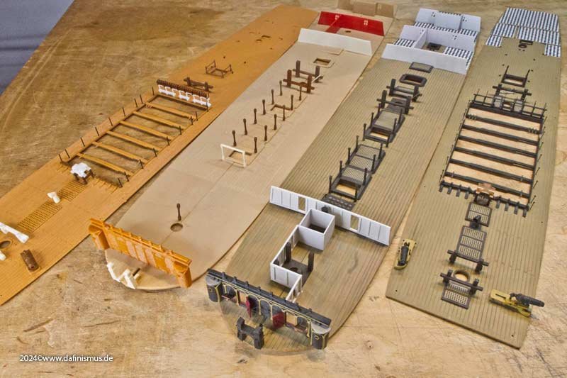
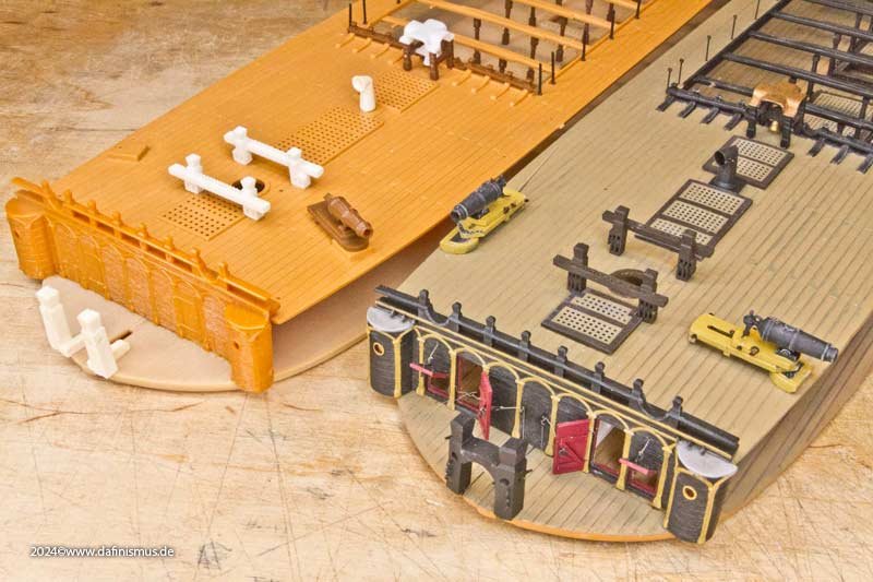
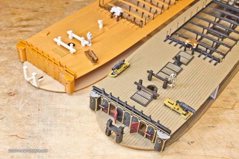
And to finalise this study here's a comparison between out of the box and something crafted with a little dedication 😉 First, the upper decks. And the upper battery deck. Okay – the comparison isn't entirely fair, but it looks good what you can conjure up with it 😉 XXXDAn
-
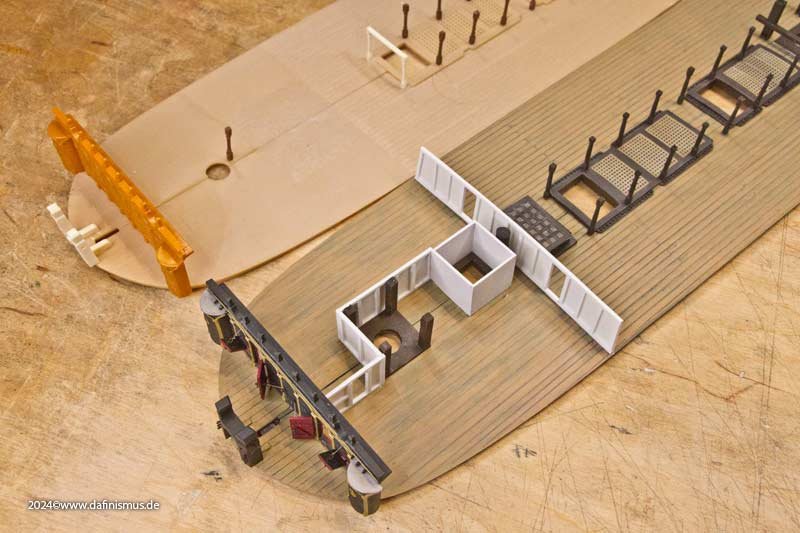
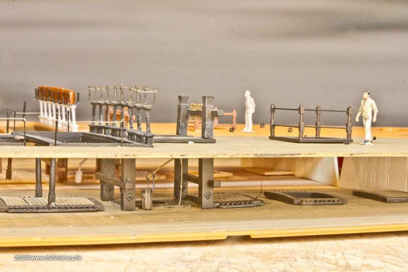
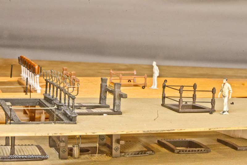
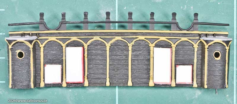
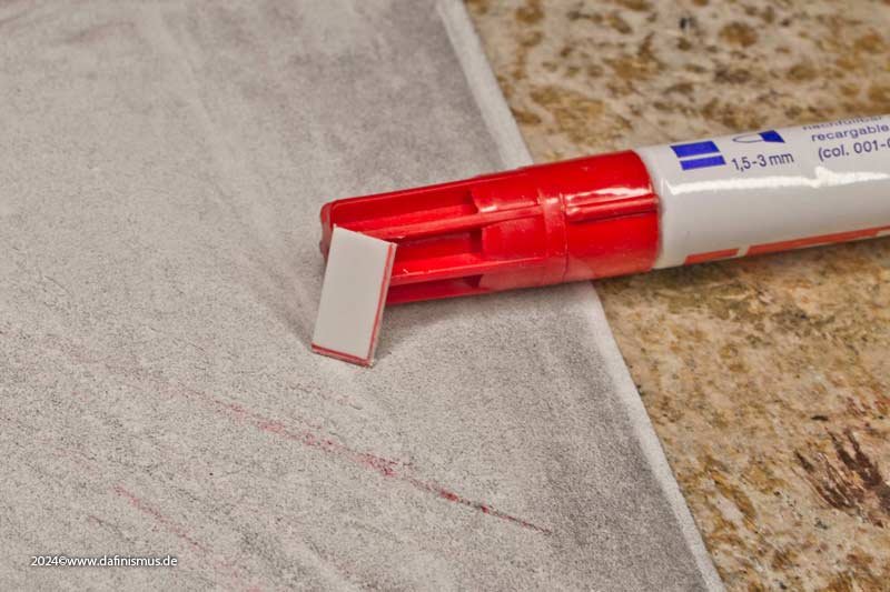
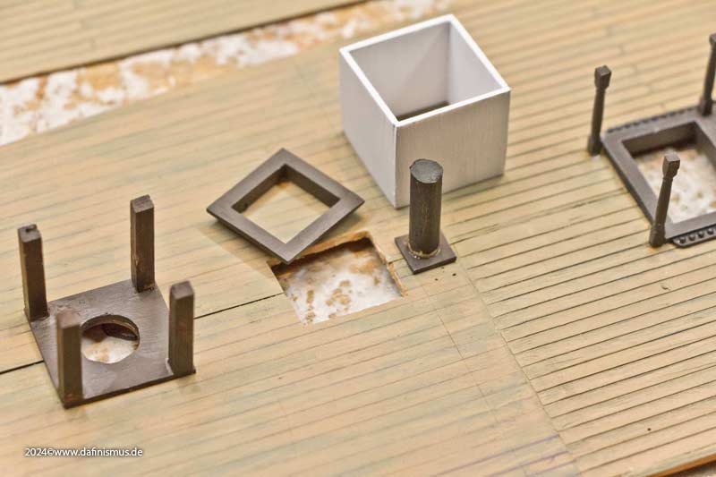
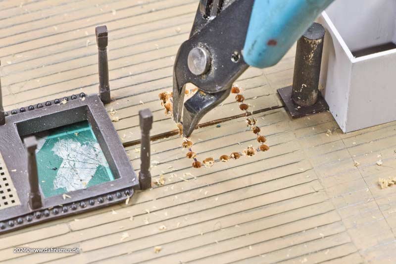
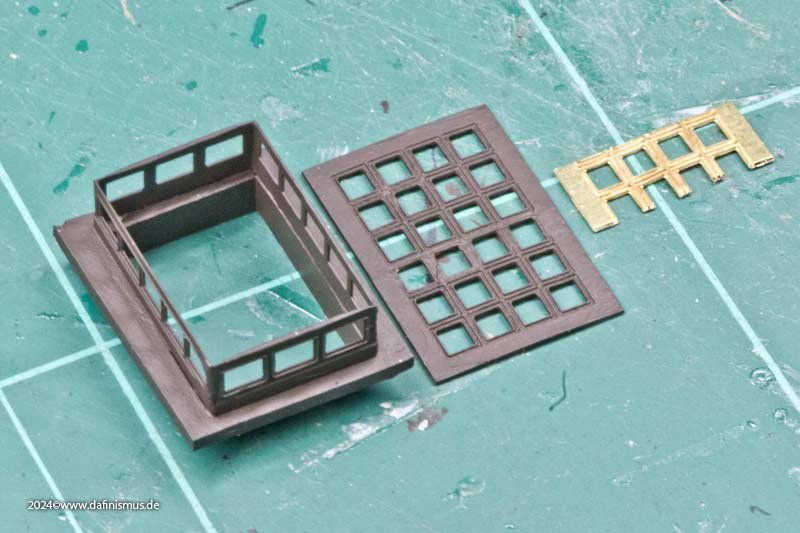
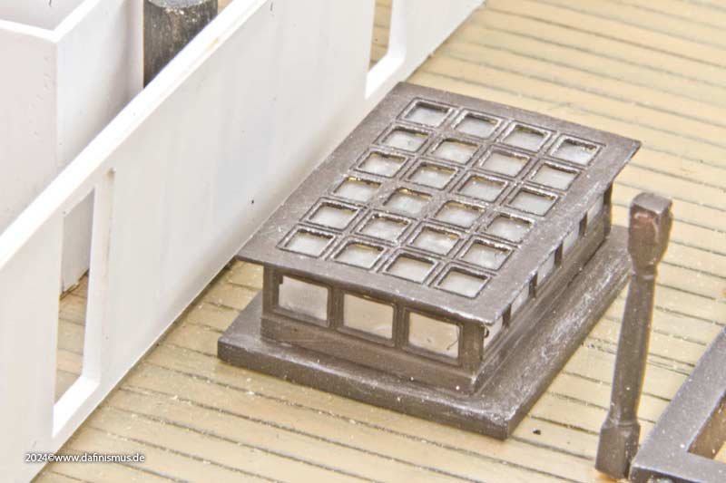
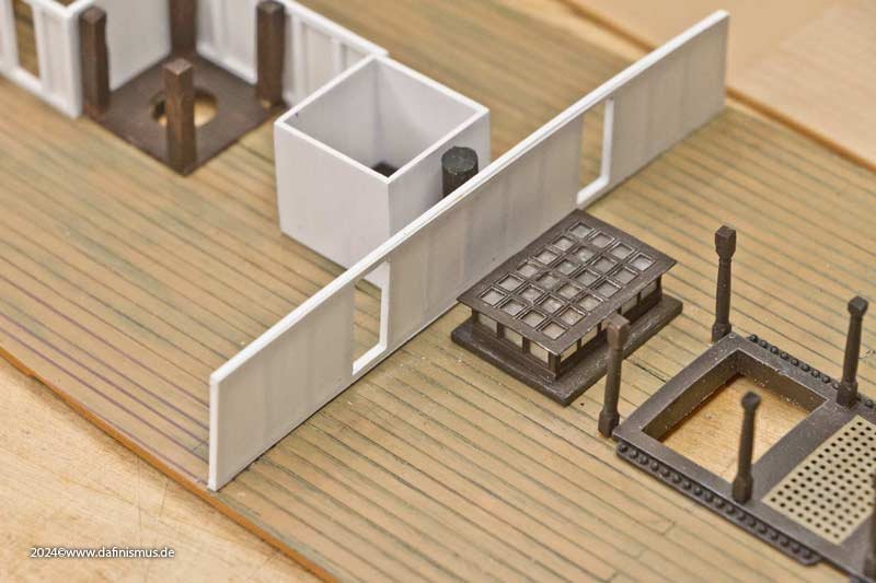
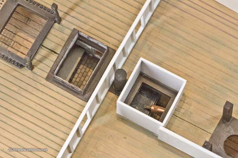
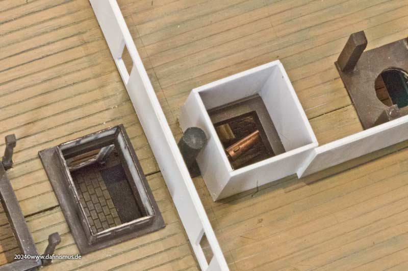
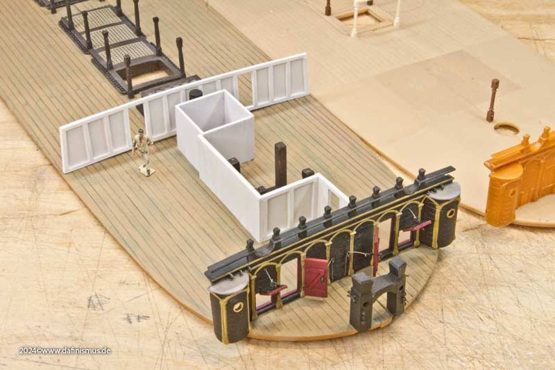
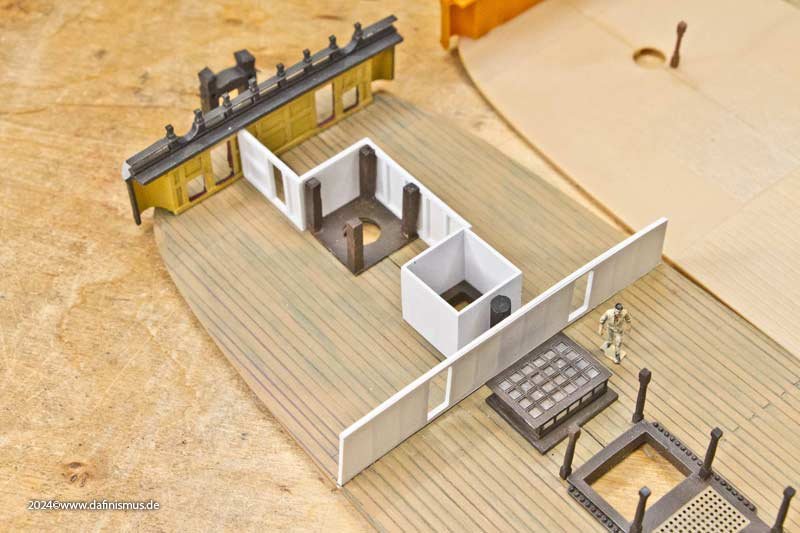
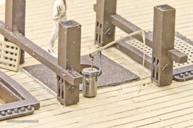
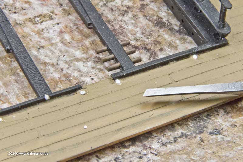
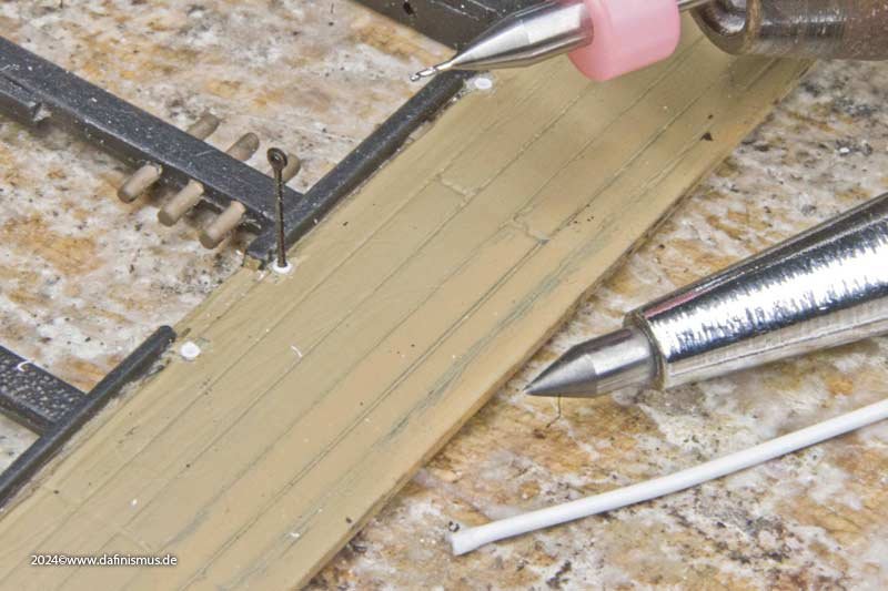
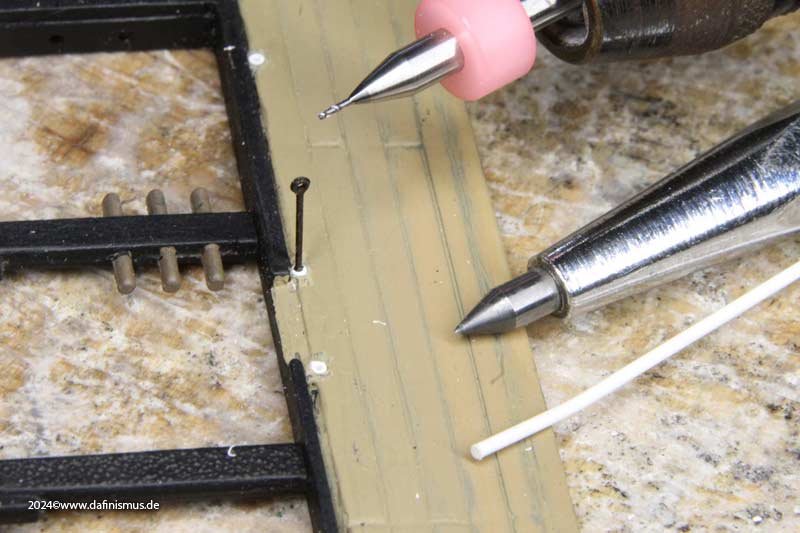
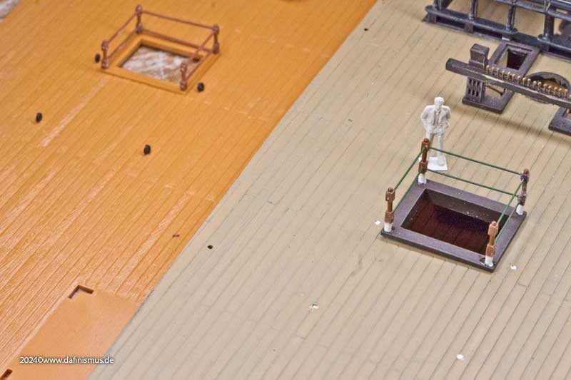
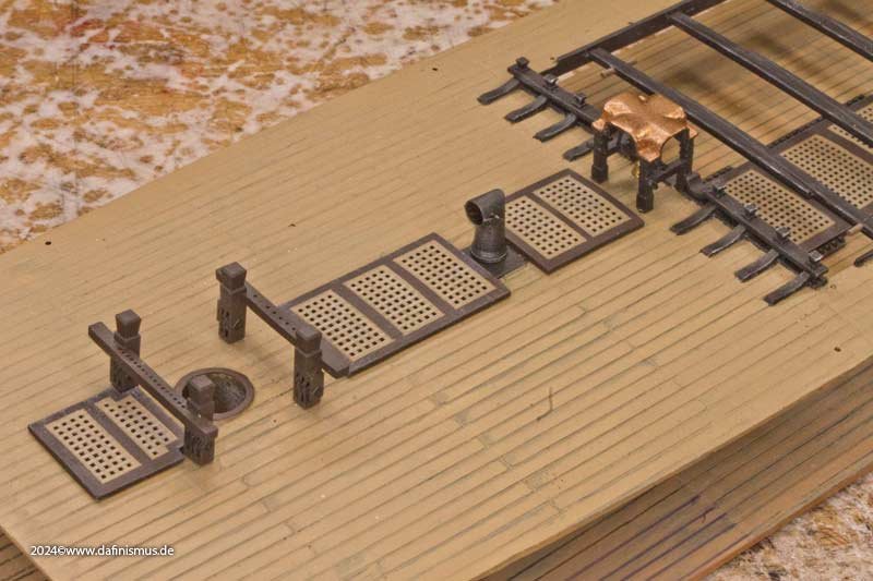
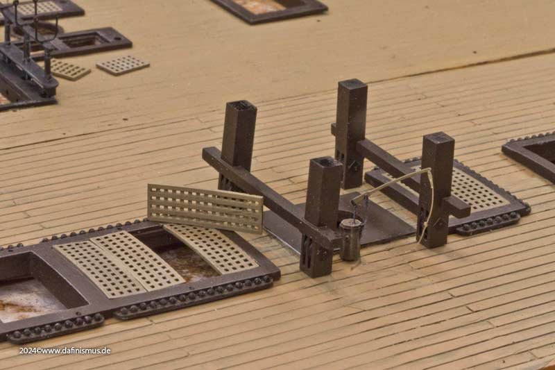
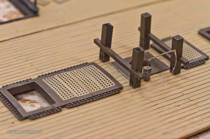
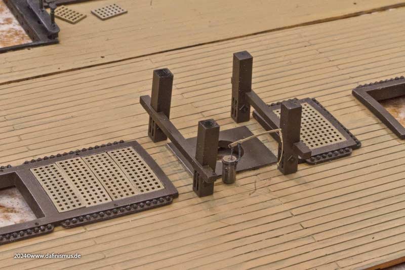
And once again, we're well into the new year, Christmas and New Year are over, and there's still no time for contemplativeness. Nevertheless, I managed to secure a little time for myself and at least finish Victory´s deck comparison. First, I jazzed up the beakhead bulkhead a bit. Since all contemporary models from around 1800 show this in black, I also decided to forego the usual blue colour. To fit in the doors, I used the old trick of applying a thin coloured strip to the side, which provides a good visual check when sanding in the tenth of a millimetre range. Then came the first additions in the freerunning section. In addition to the four supports for the foremast bitts and the stovepipe, the steam truck was added, which diverted the steam from the Brodie stove over the gratings on the forecastle. This required another open-heart surgical procedure, as another breakthrough was needed. The trunk consisted of a solidly constructed box sitting above a coaming. It was a bit tricky to position it so that the box was only under two parts of the triple grating on the forecastle and the partition wall was covered exactly. And that wasn't all, yet another hole had to be made: the kitchen skylight. So that the cooks have at least some daylight when preparing meals. To do this, the deck was perforated and opened with heavy clearing tools. Then a little scalpelling and sanding and the next hole was in. The skylight itself was a bit tricky. The part from my etch kit is two window grids too long, respectively too wide. So I cheekily cut out two grids and, after sanding the cuts down well, simply glued the remains back together with superglue. And, believe it or not, it worked 🙂 And this is what it looks like in place, and you can also see what it's for. These two openings were missing from the museum ship for a long time, and I don't even know if they have been reinstalled there in the meantime ... But you can already see the other addition: the area under the forecastle was also used as a sick bay, for which light temporary bulkheads were used, in this case painted canvas on wooden frames. If necessary, these could be quickly knocked down in the original. The lower parts of the mainmast bitts were already presented earlier. But I had to rework the positioning so that they were directly below the extensions on the quarter deck. Another popular activity was sealing the old holes on the deck, as the etched parts have a smaller diameter than the standard 1 mm holes in the kit. So 1 mm plastic rods are glued in... ... levelled, centred with a scriber and re-drilled with 0.5 mm. The supplied railing around the rear companionway also proved to be suboptimal. According to contemporary models, the principle is correct, wooden posts with iron bars, but the proportions are wrong: much too low and the bars much too thick. So a quick reworking to thinner wire bars ... ... and raising the posts, with the figure serving as a guide for the height. This completed the preparations and we were ready to take photos. Happy tinkering in the New Year from your dafi! PS: And thank you for all the nice feedback during the last year! Very appeciated.
-
 dafi reacted to a post in a topic:
Simple, low cost, small thimbles
dafi reacted to a post in a topic:
Simple, low cost, small thimbles
-
dafi reacted to a post in a topic:
HMS VICTORY (HELLER) NEWBIE HERE
-
dafi reacted to a post in a topic:
HMS VICTORY (HELLER) NEWBIE HERE
-
Matt it is! 🙂 XXXDAn
-
dafi reacted to a post in a topic:
HMS VICTORY (HELLER) NEWBIE HERE
-
Not to forget, these instructions were done more than 45 years ago and base on the 1920 reconstruction. Thus said one understand the color "cadmium yellow" being indicated in the instructions. And yes, I have pictures of the ship in cadmium yellow as it once was 🙂 Yellow ochre, sunflower yellow or yellow ochre blended with red and white (latest result, but sure not last), also feel free a bit for your own taste. The correct shade of color will surely never be revealed as even "newer" ships like Bismark there are raging discussions about this topic ... XXXDAn
-
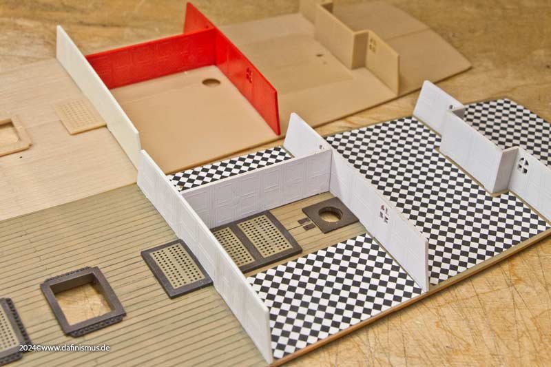
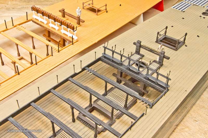
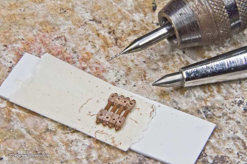
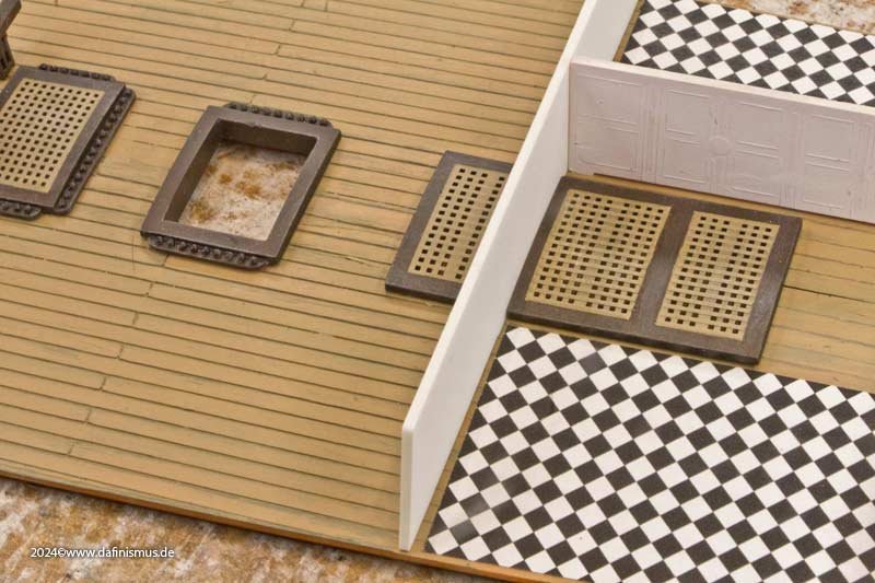
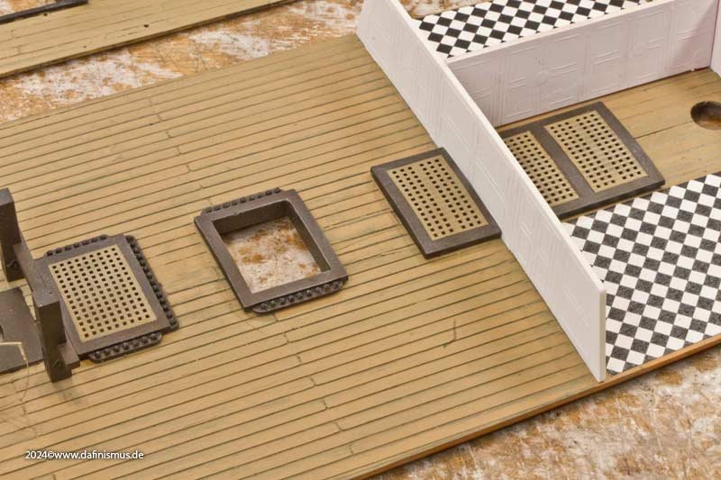
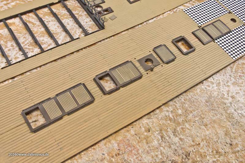
And this was the result of what I was able to complete during the public crafting session at the trade fair. The gratings also have the correct different thicknesses for the longitudinal and transverse battens on the underside. The admiral's quarters area was given a chequerboard floor. Here you can also clearly see the rollers of the bitts in the deck below. And the forecastle looks much more structured and tidier too. Well, that's it for now 🙂 XXXDAn
-
dafi reacted to a post in a topic:
HMS VICTORY (HELLER) NEWBIE HERE
-
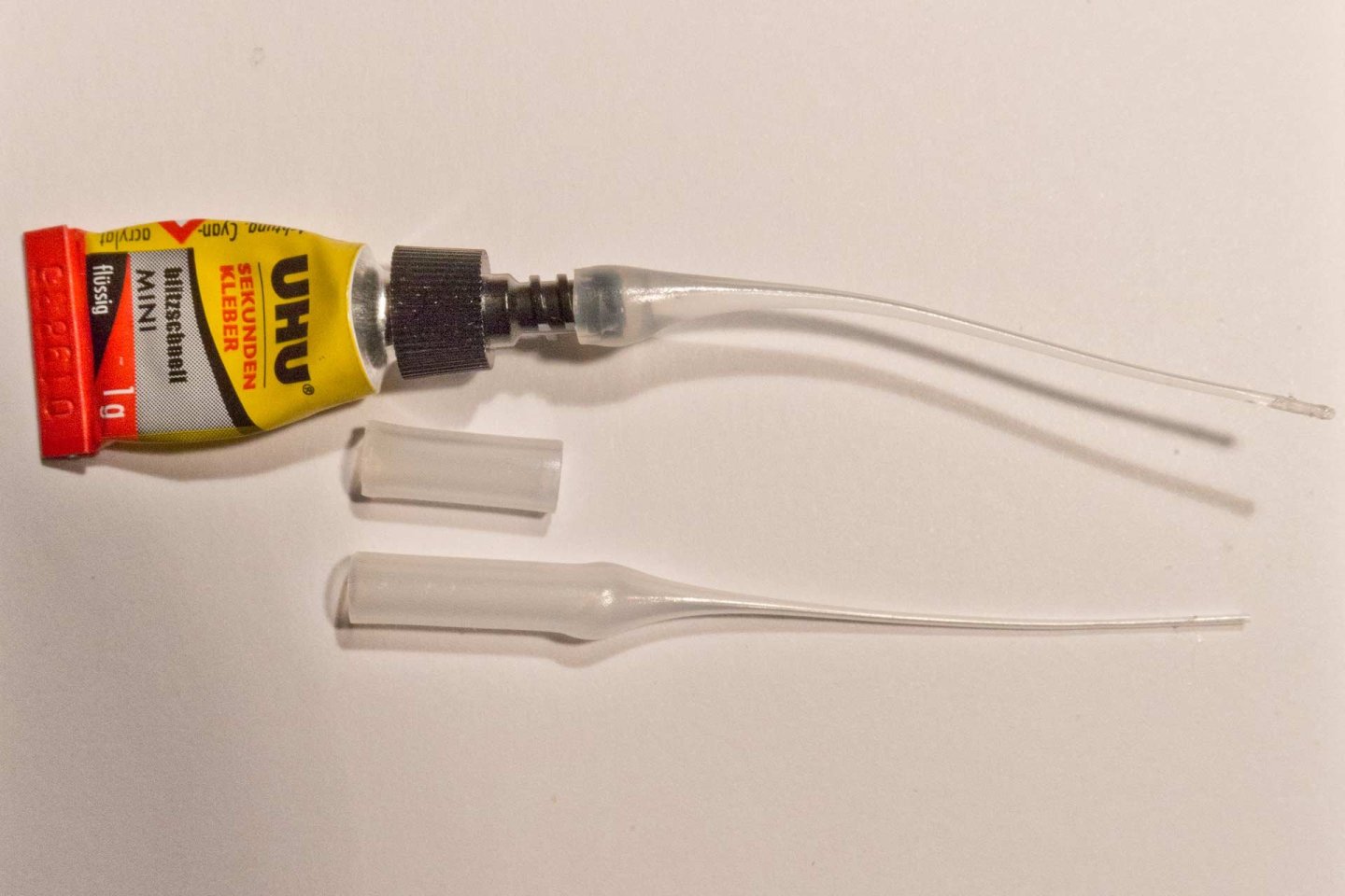
And for really tiny applications these applicators are unbeatable. They do not need to be closed and stay open for a long time. If closed, just cut off a quarter of a millimeter and its fresh again. Only safety hint: Start pressing gently until the air bubble rises. If it does not rise the tube immediately it is closed and needs to be cut. And if you cut after having applied too much pressure it will release quite a bit of glue until the over pressure is released. Otherwise this cheap things reduced the amount of wasted glue immensely! XXXDAn
-
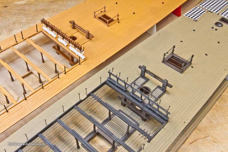
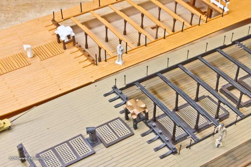
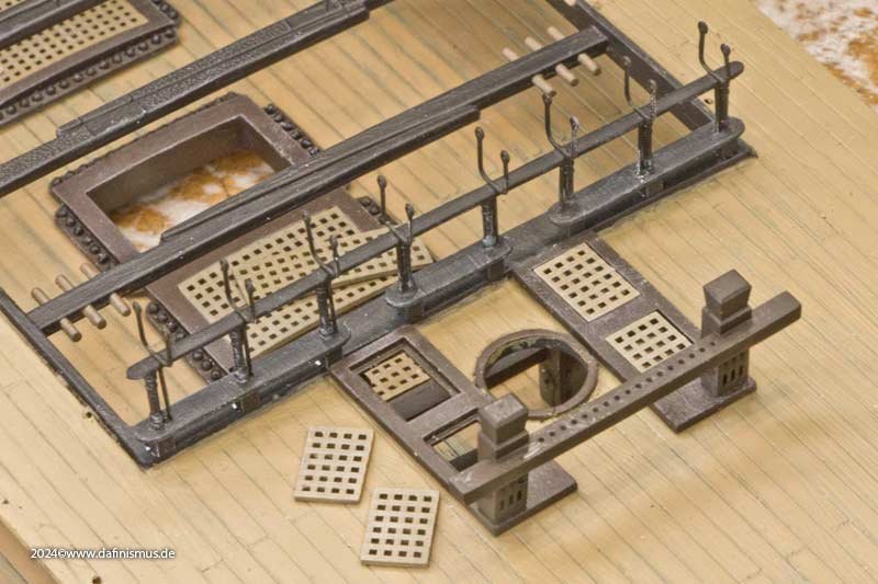
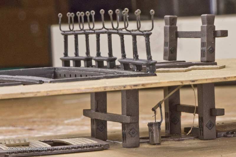
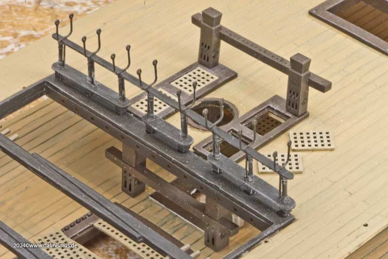
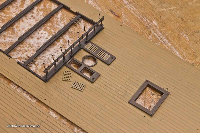
Oups, and I forgot to tell you that before the planned mess, we first had to test fit the new parts. Non-existent openings in the admiral's quarters were marked... ... cut out ... ... and adjusted to the bulkheads. The coamings and gratings were also adapted to their openings, or vice versa. And at some point, the upper battery deck was completely covered with coamings. The same procedure was followed for the forecastle and aft deck. The coamings are not as high here, as there were open decks underneath. In the area of the main mast, the gratings can be taken out, as there are some ropes leading to the bits in the deck below. This makes it easier to belay them. I also installed those bits and, as a little treat, a new hand pump was also installed there. Then the coamings were given their colour. The gratings were then masked off and painted light brown, then inked very thinly with black ink and brushed with white. And then there was the slave labour: gluing in the cannonballs... ... and securing them on the underside with thin-flow superglue. Finally, I doped the railing with the net holders... ... and add some thickness to the gangway with white Evergreen on the underside ... ... and this part of the task is finished.


-
🙂 🙂 🙂 XXXDAn
-
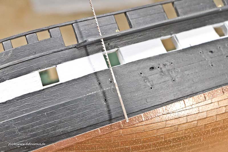
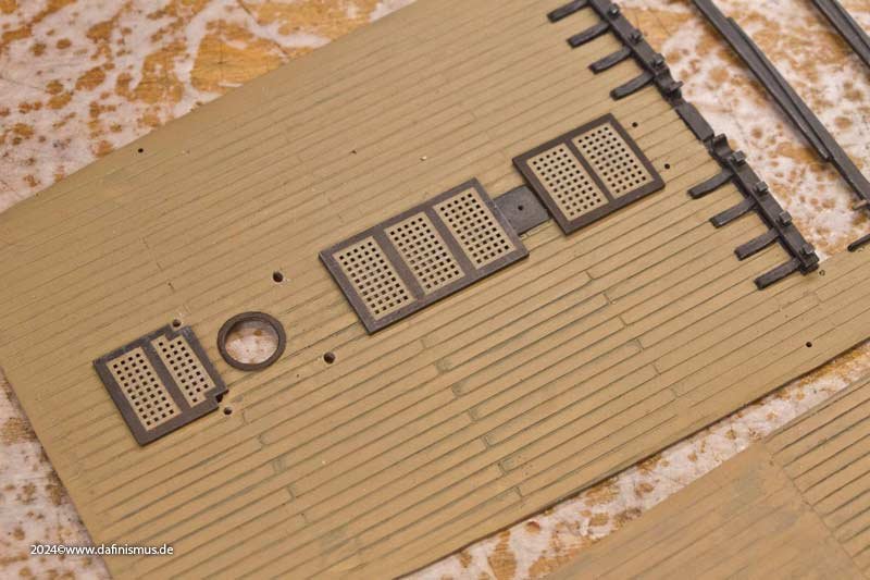
Next, I had to come to terms with the not *quite* correct planking pattern. A few beers later, I was fine ... Then I realised that the plank gaps were much too wide and would be far too prominent for my liking when filled with paint or wash. So I came up with the following plan: I sprayed the deck black ... ... and then scraped off with a blade so that the black paint remained in the depths like preshading. As always with my best plans, it ended up being a big mess. Then I tried out different shades of brown, both solvent-based, acrylic and water-based, in various opacities. It resulted in a pretty patchwork. The forecastle in particular was quite colourful ... ... which is why grey tones were used on the gangway. But what can I say, I really didn't have such a grimy deck in mind. So I sprayed it again and stripped it off again. In the meantime, I had remembered the other moulded parts, especially the gratings, which I had tuned to wood. That was the specification it had to match. And even though there are usually no major colour differences in the wood on original decks, except for traces of moisture, preshading with black prevents it from looking too much like a painted steel deck. You just have to throw your imagination a few little treats now and then to keep it happy. It was just a matter of finding the right balance. So I applied three glazed coats of paint until the black was only very faintly visible. Interestingly, the plastic of the upper deck was a light beige, while the lower deck was reddish brown. This was easily remedied by applying a grey glaze under the brown glazes. This technique also brings the area under the forecastle, which has no plank engraving, to life so well that engraving was not necessary and simple pencil strokes can substitude the engraving. I think that, given the limited visibility of this area, this is a good effort-appearance ratio. So, quickly in with the printed parts... ...and take some beauty shots.