HOLIDAY DONATION DRIVE - SUPPORT MSW - DO YOUR PART TO KEEP THIS GREAT FORUM GOING! (Only 20 donations so far - C'mon guys!)
×


Roger Pellett
-
Posts
4,519 -
Joined
-
Last visited
Content Type
Profiles
Forums
Gallery
Events
Everything posted by Roger Pellett
-
Do modern marine anti fouling paints provide protection from shipworms?
-
This looks like an interesting project. I look forward to following along. Roger
-
I wouldn’t put them in water. Instead, I’d wipe the planked hull down with a damp cloth to raise the grain, then sand. This is an old gunsmith’s trick; wetting wooden gunstocks and rubbing them down until the grain ceases to raise. Roger
-
I don’t know what scale your model is being built to but keep this in mind. Copper sheathing was nailed not bolted, to the hull with flat head tacks. The flat head was necessary to spread out the load from the tack against the thin copper sheathing. The tack head had a diameter of about 1/2in. Now assume that your model is being built to a scale of 1:64. Someone viewing your model from a distance of 1ft would be equivalent to someone viewing the real thing at a distance of 64 feet. At 64 feet would you see the head of a 1/2in diameter flat head tack? Roger
-
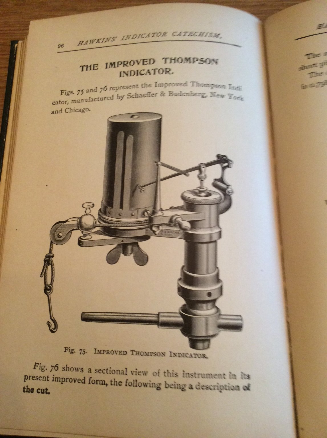
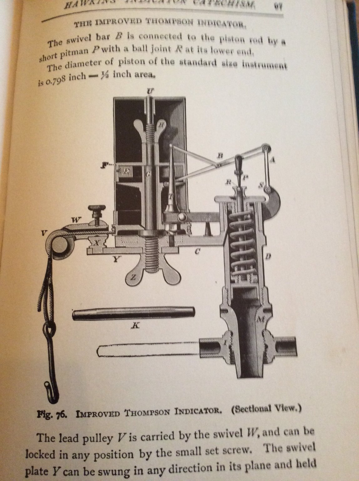
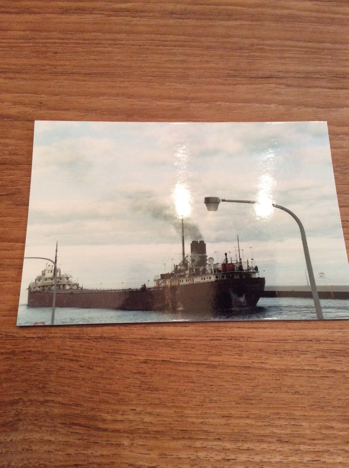
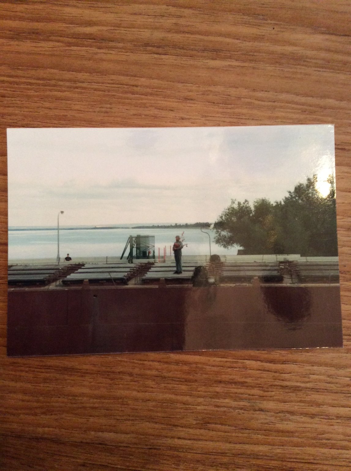
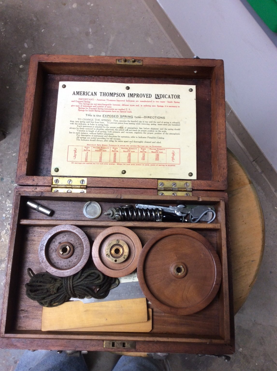
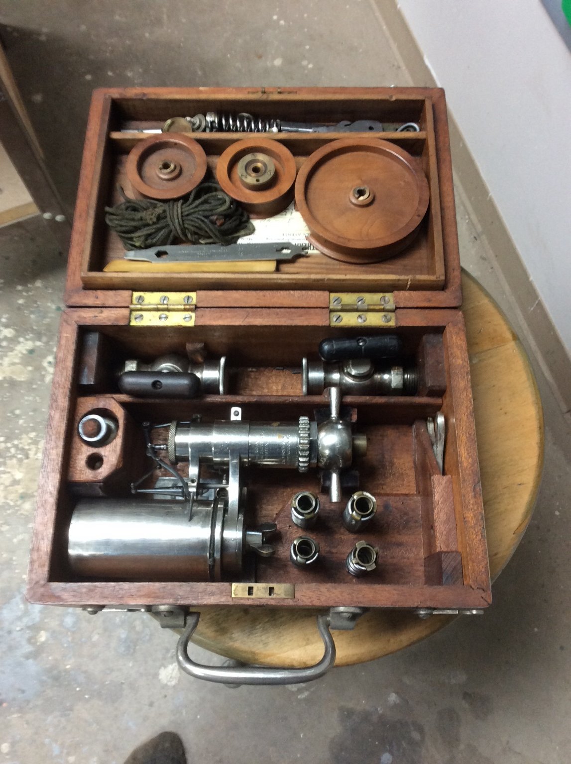
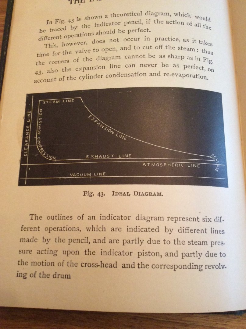
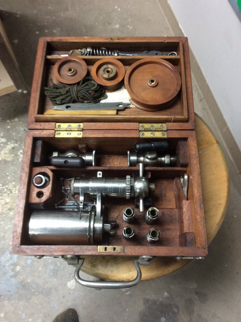
Chapter 7 Marine Engineering (Conclusion) Work continues to detail the hull halves. Hopefully by next Sunday I should have some pictures to show you. Meanwhile, I hope that you will indulge me with a little more Marine Engineering. First, two drawings of the indicator in my collection: The spring loaded piston is piped up to the engine cylinder and forces from steam pressure balanced by the spring compression pushes the cylinder up and down actuating the stylus pushing against the cylinder. A piece of paper has been wrapped around the cylinder. Different springs can be used to match anticipated steam pressure. Meanwhile the drum is rotated by the string connected via the wooden wheels to the piston rod of the engine. The resulting trace of steam pressure vs cylinder volume looks like this: Without going into the math, the horsepower output is proportional to the area within the diagram. The horizontal “steam line” on the diagram represents steam at inlet pressure entering the engine cylinder before the piston moving in the cylinder causes the valve to close. On the 1896 triple expansion engine aboard the SS Meteor Whaleback Museum Ship there are handwheels on the valve train to adjust this “cutoff. This brings up a question. History is full of stories of steamboat races and emergencies where the captain demands more power from the engineers. The engineers often respond by stoking up the boilers and gagging the relief valves. Assuming that boiler capacity existed, why not just adjust the cutoff to admit more steam into the cylinder? Maybe, that’s what they did but gagging the relief valves makes for a better story. And finally, I’ll close out this chapter with a personal memoir. I arrived in Duluth from Marietta, Ohio in May of 1989 to accept a new job. When I arrived, the company was moving to a new shop and headquarters at the end of a slip in the Duluth Harbor. From my office, I could see the channel that ships used to get to and from the loading docks in the harbor. While finishing up one evening, I noticed an old “straight deck” lake freighter heading down the channel to pass under the lift bridge into the lake. I was able to drive to the ship canal leading out to the lake before the boat reached the bridge at the entrance to the canal. The ship was the Henry Steinbrenner and as she passed by, there stood a bagpiper on a hatch playing Amazing Grace. It should have been Auld Lang Syne because after unloading her cargo of grain at Buffalo, NY she went to the scrap yard. She was the last coal fired reciprocating straight deck ship operating on the Lakes. The other coal fired old timer still operating on the Lakes, the Irvin L. Clymer was scrapped two years later in Duluth. She was a self unloader. Truly the end of an Era. Today, I count just 5 steam powered American flagged ships active on the Lakes- all self unloading, oil fired, steam turbine driven. The Edward T. Ryerson, the last straight deck steam ship (steam turbine) was just drydocked at Fraser Shipyard across the bay from Duluth in Superior, WI after sitting idle for several years. Maybe she’s going back into service.


-
A fascinating project. It would be interesting to build a second model representing the Collier Jupiter using the same kit supplied hull. I seem to remember that the plans were published in the Journal many years ago. Roger
-
Your friend gave you a nice piece of equipment!
-
Creepy!!!
-
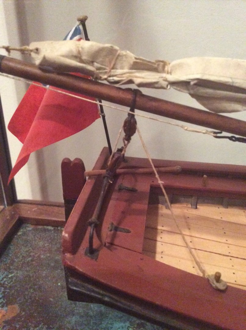
boom rigging on a ship's launch boat
Roger Pellett replied to Peanut6's topic in Masting, rigging and sails
I would suggest belaying pins rather than cleats as these can be easily removed when the boat is not rigged to sail. Murphy is alive and well at sea; especially aboard small boats. Someone fouling clothing or equipment on a cleat during a night cutting out action would need to be avoided. Roger -
I believe that it is necessary to differentiate between jibs set on a stay and those set flying. In the pictures posted above the sail is handed to a stay so the luff is controlled by the stay. Jibs set flying are different animals. While setting and lowering them when hauled out to the end of the bowsprit or jib boom there is no way to control this large bundle of canvas. Hauling it inboard where the crew can safely handle when lowering it and it and setting it in stops solves this control problem. Roger
-
As they used to say in the Navy, “If you can’t get your job done during the 24 day, work nights.” Roger
-
Congratulations Mark! You’re close enough. It’s a steam engine indicator. It was used to set the “cutoff” on the engine’s valve. The cutoff is the point in the piston’s stroke where the valve admitting steam into the engine’s cylinder closes. From that point on, mechanical power is obtained purely by expansion of steam. The point where this cutoff was to be set triggered a remarkably nasty debate between steam engineers about the time of the Civil War. Early theory argued for a short cutoff; less steam, more expansion used less energy and allowed smaller boilers. To refute this, the American Naval Officer and Marine Engineer, Benjamin Franklin Isherwood ran a series of tests that proved that “short cutoff engine’s” would be underpowered. The parallels between Isherwood and Admiral Rickover, another Great Marine Engineer working approximately 100 years later are interesting. The indicator actually makes a paper trace of the pressure: volume relationship within the engine cylinder during the working cycle. This diagram could then be used to calculate the cylinder’s horsepower output. Hence the term “indicated horsepower” or ihp. Roger

-
A beautiful and interesting model
-
I have the Nef Book too and don’t speak German. The drawings are good and understandable.
-
Windfilled sails with silk span
Roger Pellett replied to Markus16's topic in Masting, rigging and sails
Unfortunately it (my balloon cloth) also made good muzzleloading rifle patches. -
Were these small tractors like the Ford really that much heavier than the towed rig shown in the video? I can understand that the massive machines used today are.
-
Not just setting it. Lowering it without first bringing it inboard via a traveler runs the risk of dumping it in the drink and sailing over it. There are several contemporary prints from the 1700’s showing small sloops with furled sails where the jib is run out to the end of The bowsprit but hoisted In stops, presumably to be set by pulling on the sheets. I rigged my Longboat mode.l this way. Roger
-
Chapter 7 Marine Engineering Work continues on detailing the two hull haves prior to joining them. I will describe these details in my next post. Meanwhile, since several of these details relate to the ship’s steam propulsion plant, this Chapter is devoted to Marine Engineering. Naval Architects design and build ships. Marine Engineers design the mechanical and electrical systems that propel them and furnish energy for other on board needs. Today, Naval Architects joke that Marine Engineering is nothing more than selecting a Diesel engine from a catalog, but in the 1960’s when I went to school, for American ships, steam was still king so Marine Engineers had to integrate equipment to produce a workable steam plant. When Benjamin Noble was built in 1909, for ships sailing the Great Lakes, Marine Engineering meant coal fired Scotch Marine Boilers providing steam to a reciprocating triple expansion engine, steam deck machinery, steam reciprocating pumps and possibly one or two small reciprocating steam driven “dynamos” providing electricity for lighting. Although there were two other machinery choices, neither was considered suitable for use on the Lakes and the coal burning reciprocating engine steam plant would be the dominant prime mover for US Great Lakes ships throughout the first two thirds of the Twentieth Century, with a few of these still operating into the 1990’s. As this is written, the repurposed SS Badger Railroad Car Ferry with coal fired boilers and two Skinner Uniflow reciprocating engines still ferries people, cars, and trucks across Lake Michigan. The two other choices were steam turbine and Diesel. Both of these were considered at the time, to be unsuitable for Great Lakes Service. In 1909, Diesel was A newcomer with two major disadvantages. The first was fuel. In 1909 coal was king along the Lakes with fueling docks spotted along the shipping lanes. Petroleum products in bulk quantities to fuel large Diesel engines were not widely available away from the few refining centers. Diesel engines were also difficult to reverse. While inventors offered various linkages to reverse by changing the timing of the cycle, these all involved a complicated sequence to shut the engine down and to restart it in the opposite direction. When Diesel engines finally became popular on the Lakes in the 1970’s they were paired with controllable pitch propellers to solve the reversing problem. While steam turbines could and would operate with coal fired boilers there were other difficulties with their use. First, like Diesel’s they were hard to reverse. While the solution would be to pair them with smaller separate reversing turbines this was not ideal when maneuvering in the narrow canals, rivers, and small harbors of the Lakes. The second problem involved speed. Steam turbines work most efficiently at high rotational speeds. Screw propellers in water work best at low speeds. The ultimate solution to this problem was a set of very large reduction gears to connect turbine and propeller but these gears required special manufacturing capabilities not widely available in the US at the time. The first geared turbine steam plants would not be used to propel American ships on the Lakes until the late 1930’s. So, the reciprocating steam engine was well suited for use on the Lakes. They could be easily and quickly reversed, they were relatively easy to manufacture, and were efficient operating at low speeds that matched that of the propeller. While their thermal efficiency was low, this was not a concern. The distance from the Lake Superior iron ore loading ports to the Lake Erie unloading ports is slightly less than 900 miles; short by comparison to Ocean shipping distances, coal was cheap, and several of The Steamship Companies had parent companies that owned coal mines. These engines were also remarkably low powered. Benjamin Noble’s engine produced only 800ihp (indicated horsepower) and a vessel with 1800ihp was considered high powered. The last US steam powered Lake Vessels built in the 1950’s had steam turbines with outputs of 7000 shp, over 10 times that of the Noble. Ships designed to sail only on the Lakes did not have to contend with salt water. This allowed use of a simple device from the beginning of marine steam propulsion- The jet condenser. Steam expanded from its boiler pressure and temperature still has considerable energy at atmospheric pressure. To make use of this energy, the steam must ultimately be rejected to a lower temperature heat sink. The third and last cylinder of the triple expansion engine, therefore, exhausted into a low temperature chamber called a condenser. Ships operating in salt water used shell and tube heat exchangers for condenser to prevent salt water from mixing with the condensed steam and fouling the boilers. Ships on the Great Lakes often used a simpler Jet Condenser that mixed steam directly with water drawn from the lake. Much of this condensed steam water mix was pumped overboard with a fraction returned to the boiler. The engineer on watch was, among other things, was responsible for controlling the flow of water into the Jet condenser from the lake. Too little and he would lose the vacuum in the third cylinder. Too much and he risked flooding the cylinder with incompressible water and locking up the engine. The heavy stream of water seen in all photos of old Great Lakes Ships cascading from the side of the hull is the discharge from the condenser. And finally if you’ve followed me this far a quiz! Can anyone identify this equipment from my collection that was used in the engine room of the Great Lakes ore carrier Henry Rogers? Roger
-
Pin Vice Help Needed
Roger Pellett replied to Ed Gibbons's topic in Modeling tools and Workshop Equipment
A while ago I decided to replace my used and abused set. I chose the ones from Amazon that were made in USA. It turned out that they were from a company called Moody in Rhode Island, moodytools.com. I thought that there were nicely made. A four vice set bought directly from the company lists for $66.00 Roger -
Wonderful work! Just deciphering the complicated mechanism would be a major challenge let alone producing it. As noted above, here in the US there are antique agricultural equipment shows throughout the US, usually in late summer and anything steam powered becomes the star of the show. County fairs throughout the US often feature tractor pulling contests, which have resulted in some crazy custom equipment; multiple engines ,jet engines, etc. I remember back in the late ‘50’s when this sport was in its infancy, internal combustion powered equipment had a hard time competing with the “steamers.” When gas or diesel powered equipment approached their limit their engines would stall. This was not a problem with steam as it would continue to push against the cylinders at very low speeds or even standing still. As a result, least at our local fair in Ohio, the steamers were separated into their own class. Roger
-
John, An interesting ship. I look forward to following your progress. I grew up in Akron, Ohio where my father worked for BF Goodrich and the company brought well known speakers to town to educate and entertain their employees and their families. I remember as a child, listening to Donald McMillian discuss his expeditions complete with color slides. Vintage 1950’s! In 1966, the Navy ordered me to Groton, CT to familiarize myself in nuclear submarine construction operations. A highlight was hands on training at Electric Boat’s pipe welding school in what is now the library for Mystic Seaport. This gave me the opportunity to visit the Seaport in off duty hours. Much to my surprise Bowdoin was one of the vessels on display. I don’t remember being able to go onboard. If my memory is correct, her hull shape was designed specifically for ice operations; the idea being that forces from ice would cause the hull to lift rather than crush. Like squeezing a watermelon seed! Roger
- 127 replies
-
- 2
-

-
- Bowdoin
- Arctic Exploration
- (and 3 more)
-
boom rigging on a ship's launch boat
Roger Pellett replied to Peanut6's topic in Masting, rigging and sails
Back in the day when I was taught to sail a small, centerboard, boat I was told to never belay the main sheet. Interestingly this advice is repeated in at least one Mid Nineteenth Century Seamanship manual dealing with warship boat sailing. On the other hand, these “small boats” were anything but small by today’s standards. The 23ft Bounty is about as long as a small cruising sailboat and the rigs were powerful. When I rigged the main sheet on the Longboat I thought, How could the mainsheet be controlled by one man without belaying it? Expecting one man to control it led from the end of the main boom seemed ergonomically impossible. By leading it to a pin on sternsheet it could be snubbed, not belayed and payed out as necessary. When the boat was not rigged for sailing the pin could be easily removed. Roger -
boom rigging on a ship's launch boat
Roger Pellett replied to Peanut6's topic in Masting, rigging and sails
Kev, The photo below shows the main sheet rigging for my 1:32 scale scratch built Longboat model. The rig is the short gaff loose foot variation that I discussed above. The tackle as rigged gives a 3:1 Mechanical advantage. Some time ago there was a spirited debate on the forum weather the main sheet horse should run above or below the tiller. There were two schools of thought. The Museum Model school claimed that since rigged model(s) in the NMM Collection show the horse below the tiller, this must be accurate. The practical sailor school maintained that this arrangement and anything like disconnecting the tiller from the rudder during tacking would lead to disaster, and in my case I have the (wet) tee shirt to prove it. This and other Longboat rigging info should still be available on the forum. Try searching “Longboat rigging.” Roger