

Seventynet
-
Posts
735 -
Joined
-
Last visited
Reputation Activity
-

 Seventynet reacted to jpalmer1970 in The Hayling Hoy by jpalmer1970 - 1:48 scale - First POF build
Just a small update on the latest work.
I firstly purchased some more Australian myrtle from my local supplier - some thinner 10mm sheets and some 45mm deep pieces. Hopefully this stash will keep me going for quite some time. I haven't yet worked out exactly how much wood I need for the frames etc but I plan to have a look at that at some point in the coming weeks.
I also continued working on the keel and stem pieces. The lower and upper stem pieces were cut out of the 12" stock. I actually had to make another lower stem after some wayward sanding of the first attempt but I have now managed to get the two stem pieces to fit together nicely. I shaped the lower stem boxing joint and so far everything seems to be lining up well but I do need to cut out the recess on it for it to fit against the keel. I realised after the fact that it would probably have been easier to make the joint on the lower stem first and use that as a template with which to cut out the boxing joint on the keel, rather than the other way around - but that is one of the learning experiences.
I also cut the three keel sections to length and made the forward scarph joint. I cut this scarph with the table saw and may have gone a hair too deep with my cut but I will need to wait until I decide on how I am going to line the joints to see if it was too much. Tissue paper or thin paper may be enough to 'pad' out the joint perhaps. it won't be noticeable from the side of the keel but I do need to ensure that the joint is strongly glued. I have been reading the discussion on how to simulate the effect of the tarred joints in @Pirate adam's build log of the Crocodile and so i will experiment with the various methods suggested there. As the myrtle has a reddish hue I think a black joint may provide more contrast than a brown one but we will see.
Finally it was good to actually put the keel pieces onto the building board so that it looks like I have made som progress 😀. Nothing is glued or fixed at all so far as there is still much more to do to the keel in the coming weeks.
-
Seventynet reacted to Rustyj in Sloop Speedwell 1752 by Rustyj - Syren Ship Model Company - 1:32 Scale - POF Sloop
Moving along I've finished the boxing joint and the first parts of the keel.
Next I'll add the false keel and the pieces on top of the keel for the rabbet strip.
-
Seventynet reacted to Paul Jarman in Type of glue to use planking a hull
Personality I would never use CA glue for planking.I have used Vitalbond Aliphatic professional wood glue for all my models.It's essentially a wood super glue. And holds the plank to the bulkhead just fine. I then use a normal white PVA wood glue for second planking as there is more area fror the glue to grab.
The only time I've used CA glue for planking is on occasional areas that have a lot of spring in them
Paul
-
 Seventynet reacted to Isaiah in Perseverance 1807 by Isaiah - FINISHED - Modellers Shipyard - Colonial Brig
Here’s the Perseverance, my first model ship, fully complete after 15 months.
I’ve learnt a lot over the course of building this kit, real life and model building. Even though there’s many flaws and inaccuracies, I’m still quite proud of this accomplishment. My main goal was to resemble something that looked like a wooden ship and I’m pretty sure I achieved that!
Thanks to all who followed along
and a big thanks goes to Michael and Steven, you’ve been a big help.
@Ferrus Manus
@Louie da fly
Until next time,
Isaiah
-
Seventynet reacted to Isaiah in Perseverance 1807 by Isaiah - FINISHED - Modellers Shipyard - Colonial Brig
All rigging is done, Almost there!
Just the flags and 35 rope hanks to go.
-
Seventynet reacted to Chuck in Sloop Speedwell 1752 by Chuck - Ketch Rigged Sloop - POF - prototype build
Thank You...
The cabins on the aft lower platform are completed. No detailed explanation since they are built exactly like the others. Each partition wall is built up with two layers glued together. Then they are detailed with hinges and door handles as required along with any upright timbers 1/8" x 1/8" strips. Their heights and widths are adjusted to fit under the deck beams etc. Finally they are assembled and glued into position.
Here is the tiny powder and filling rooms completed. These walls are slightly thicker than the other cabins as was normally the case. An extra laser cut sheet of parts shows how all the cabins are prepared for you. They are all numbered and shown on the plans. I built them in the order that they are numbered.
All of the cabins completed.
Next up is to complete the remaining deck beams carlings and ledges.
-
Seventynet reacted to Martes in Age of Sail 2 - 3d ship models for PC wargame
While I am procrastinating with the Salamandre, I did a couple of fixes for Liffey and Schpitzbergen, correcting the run of the deck aft on both, and replacing the boats with a slightly better placeholder models.
-
Seventynet reacted to JeffT in Sloop Speedwell 1752 by JeffT - Syren Ship Model Company - 1:32 scale - POF Sloop
A little more progress. Finished the stem. Not perfect but I do like the way its going so far. Also tapered the stem and joined the front part of the keel.
-
Seventynet reacted to JeffT in Sloop Speedwell 1752 by JeffT - Syren Ship Model Company - 1:32 scale - POF Sloop
Just a few pictures of whats in the box. Had a few items shake loose in transport so needed to make sure I got everything back where I belong. I also printed a few parts of the plan as a test. Was able to get the copies of the plans done too.
-
Seventynet reacted to Rustyj in Sloop Speedwell 1752 by Rustyj - Syren Ship Model Company - 1:32 Scale - POF Sloop
It was mentioned earlier that it's best to sand pieces prior to removing the from the billets. The way I do it is with a sanding block. I use 180 the 320 grit sandpaper. It's self-adhesive. It is also handy for finish sanding completed pieces like the stem. I usually use Minwax wipe on poly. My local store was out but they did have Watco satin wipe on poly. I've used other Watco products and liked them so I gave it a try. It's a little thicker than the Minwax but covers nice and looks the same.
Next I'll start working on the keel. Oh this is fun!
-
Seventynet reacted to Jim Rogers in Sloop Speedwell 1752 by Jim Rogers - Syren Ship Model Company - 1:32 scale - POF Sloop
Next I painted the figurehead. I plan on painting and staining my model as I always do.
-
Seventynet reacted to Erik W in HM Cutter Cheerful 1806 by Erik W - 1:48 scale
After pulling some hair out, and the remainder going gray, haha, I have finished the backstay plates and chain plates . . . on the port side anyway. I revisited blackening them, using advice here and on the internet. My test brass strips looked OK, but I couldn't avoid bare brass spots being rubbed off after lightly wiping them down with a dry cloth. I'm pretty sure I didn't clean the brass well enough beforehand. After being left frustrated by that, I just went ahead and followed what Chuck had done on his, and painted them black and used a rust brown weathering powder to give them that iron look. I'm happy with the results. A trick I learned years ago as a model railroader with brass, is to bake the brass after painting. Just put the parts under a hot halogen or incandescence light bulb, about an inch away from the bulb, for about five minutes. This hardens the paint on the metal surface and makes it much more scuff resistant. The nails themselves I ordered from ModelExpo (being my first ship build I didn't have any extras from prior builds to use). They are the smallest ones they offer. They're slightly rounded on the bottom of the heads, so don't appear the sit flush when pushed in. So I used a larger diameter drill bit than the holes in the brass were drilled with, and counter sunk all the holes in the backstay and chain plates. I also ran a sharp angled file on the underside of the heads of each nail. This helped get the nails to snug down flat when pushed in. After getting the parts mounted and nailed in place, I went ahead and touched up the paint and weathering powder.
Of all the processes involved on this build, metal working is probably the one I have the least experience in. The backstay plates and chain plates have taken a lot longer than I thought they would. That said, I've learned a lot, even with the error part of Trial and Error being frustrating at times!
Erik
-
Seventynet reacted to Erik W in HM Cutter Cheerful 1806 by Erik W - 1:48 scale
With longer days, and warmer weather, progress has slowed down as my focus has shifted a bit to being outdoors more as spring arrives. I do still work on Cheerful daily though. I'm working on the chain plates. As with the backstay plates, I cut strips out of a 6" x 12" brass sheet. I then cut the 8 chain plates longer than needed. Next I shaped the tops of all 8. Being my first ship build, I had to do some research when I got to Chuck's instructions, "Assuming this isn't your first ship model, the angles for each chain plate were found in the usual way." Glenn (glbarlow) had some good photos in his Cheerful build log that show how to rig a temporary mast to get the desired chain plate angles. I made a jig to get the rake of the mast correct, when compared to the plans. Then I secured the mast in place with temporary fore and aft stays. The simulated shrouds are tied off at the correct height and spacing on the mast. Knowing the chain plates are not exactly the same length this process was key to do before I cut them to length and drilled the lower 2 holes on each chain plate. I have the port side chain plates finished more or less (they do still need a little tweaking). Each one is marked on the back for which position it belongs in.
Erik
-
Seventynet reacted to 0Seahorse in 17th-Century Speeljacht by 0Seahorse - FINISHED - scale 1/50 - CARD
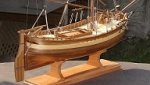
It took a long time to finish the hull, but it can finally be presented.
In accordance with period drawings, I applied thick nails (glue and paint) on the wales, and attached two pairs of reinforcements to the stem.
All the finishing touches and modest decorations appeared. Initially, I thought about cutting them with a laser, but it would require some plasticizing (e.g. with glue) and painting - which means a lot of work and time. So I cut out several copies by hand with a sharp scalpel and glued them to the sides. The decorative ends of the railings are simple bottomless "boxes" that I used to mask the ends of the edges of the railing.
In the stern part there are belaying pins printed in resin , a bench and a rod on which the sheet of the second sail moved. And a few little things at the stern.
All decorations are "conventional", i.e. you can make others according to your own intuition and skills.
Leeboards, characteristic for coastal units that moved in shallow waters, according to the plans, had semi-circular indentations - after gluing such a part, I gently cut out these indentations with a scalpel, corrected them with a file and covered the whole thing with strips. They were hung with an eye on a hook coming from the side. They were lifted by ropes, which is clearly visible in the photos.
A few more words about the rudder blade, which unfortunately I don't have any photos of. A simplified version would consist of layers of cardboard and that's it. Usually, however, the rudder blade was thicker at the front edge and thinner at the rear. That's what I did: the side layers of 0.5 mm cardboard are glued together at the back, and an additional narrow strip of cardboard is glued between at the front. This can be seen on the masking strips. The front edge (where hinges are) was not perpendicular, but ended at an angle - the glued side parts in the color have appropriate protrusions at the front, which, glued together, create a triangular ending. The recesses for the hinge axles are, of course, masked with another small strips. The thicker upper part of the stern blade, where the tiller is mounted, was created by appropriate shaping and simply gluing thicker cardboard between. For imaginative modelers, instead of the missing photos, I am posting a scan of the parts.
And that's all.
Regards
Tomek
-
Seventynet reacted to 0Seahorse in 17th-Century Speeljacht by 0Seahorse - FINISHED - scale 1/50 - CARD
Hello colleagues
Many modeler friends said to me that it would be nice to assemble a cardboard sailing ship, but rigging is generally too difficult. Therefore, a few years ago I asked Ab Hoving for an idea for a simple model with the simplest possible rigging, and I didn't have to wait long (2-3 hours) when a precise and immediately three-dimensional design of a "recreational yacht" appeared on my computer. ", i.e. "Speeljacht".
This design is very similar to the commercially available plans drawn by Cor Emke.
[url]https://www.modelbouwtekeningen.nl/nvm-1006017-speeljacht-volgens-nicolaas-witsen-167.html[/url]
Recreation on the water was probably not an invention of the Dutch, because in the tomb of Tutankhamun an image of the pharaoh fishing on the Nile was found, which can be considered entertainment on the water. However, until the 17th century, sailing ships of various types fulfilled basically only commercial and war functions or were used for work, such as fishing. It was only when the trade in Asia enabled merchants to build great fortunes that yachts for entertainment appeared.
Maybe it was then that "yachting" appeared as a way of spending time with family, friends or for business purposes. Not only did people relax by sailing for pleasure, but such expeditions were accompanied by delicious feasts, including plenty of drinks. Nicolaes Witsen even mentions a "beer house" under the aft deck. In addition to romantic trips, owning such a yacht meant prestige and/or wealth - a bit like modern billionaires and oligarchs.
The decorations were chic, but not flashy. The Netherlands was a Calvinist country, so one had to be modest. There was usually a family coat of arms on the stern.
A similar model was developed in wood by Kalderstock.
And for the inquisitive and curious: the Clean2Anywhere Foundation has been experimentally recycling plastic for several years, building replicas of small historical yachts from it, including this speel yacht. Link to one of the videos where you can see the construction of a speel yacht:
[url]https://www.youtube.com/watch?v=eqrIHFulcZU&t=3s[/url]
And how is my construction going? So quick and easy that I didn't take many photos, especially obvious stages like frame frames,...
...or "first - false planking"
The retouched cardboard edges of decks has always "disgusted" me, so I experimented a bit and glued narrow strips on the visible edges, imitating the face of the boards. The stripe is 0.7 mm, my hand trembled a bit and it didn't turn out perfect, but I think it's a very good idea for the future.
Since masking the edges like this has a future, I went ahead and played with the edges of the planks at the stern. There is also something to complain about, but that's my fault - I liked the idea itself.
A large number of visible frames required tedious gluing and retouching, and initially I planned to glue them to the hull first and then continue covering them with the planks. Fortunately, before I started committing such stupidity, I changed my concept and built this component separately, finally gluing the finished one to the model. In total, in four stages: 2 amidships and 2 aft.
The last layer of planks (in color) went very well, and of course the corrections were made on the edges that are covered with wales. This is how it turned out:
Modest decorations (as I wrote at the beginning) will only be made of cardboard (no resin), so that the model is fully paper as standard. It was necessary to choose the coat of arms of some noble family. The final choice fell on the van Loon family, also because their "palace" still houses a popular museum.([url]https://www.museumvanloon.nl[/url])
That's it for now, only decorations, leeboards and very simple rigging remain.
Regards
Tomek
-
Seventynet reacted to Chuck in Sloop Speedwell 1752 by Chuck - Ketch Rigged Sloop - POF - prototype build
Just a quick update. It might not look like a lot of work was done since my last post but you would be surprised how involved the deck beams can be.
With the cabins on the fore lower platform completed, you can start adding deck beams above them. No reason to wait until everything is built below deck to do so. In fact, waiting to do it all at one time wont be very enjoyable. Doing it this way breaks up the task a bit.
This kit will be very simplified compared to the books. Because we will be planking the gun deck in the "classic" contemporary model style, there is absolutely no need to make and add the hanging and lodging knees. In fact, this would up the difficulty factor by about ten. So we will just be adding the deck beams with all of the carlings and ledges. You can however follow the Seawatch books and scratch build the knees should you really want the total experience.
The photo below has a lot going on that was completed.
First, The first four deck beams were glued into position...
Then the carlings were added between them as shown on the plans. The carling are cut to length using 3/16 x 5/32 strips.
Lastly you may notice that the after most beams have a column under them at the center. These are just 1/8" x 1/8" strips cut to length. The corners are chamfered as shown on the plans.
With the first four beams added you can now add the ledges. These are the thinner "partial beams" that extend from the carlings to the deck clamp. They are laser cut for you with a special "leg" on the outboard ends. This raises each ledge to the perfect height so it will be flush with the top of the gun deck beams. So when you are cleaning the char off these...DONT sand the bottom or even the end with this "leg" on it. Otherwise you wont have level ledges with your beams. Hope that makes sense.
Now in that same photo above you can see the first few ledges (cleaned of laser char...no need to clean the bottom at all actually) resting in position. All you have to do is cut the end that sits against the carling and glue it on position.
NOTE: Now yes indeed...all of the carlings should be notched in the deck beams. All of the ledges should be notched into the carlings. But you know what...I am not going to do that. And you dont have to either. It simplifies things so much this way and those many mortices and notches are not so easy to make. They will also mostly be completely covered up. So you can decide.
Now this may all seem simple enough. But finding the exact locations for these beams, carlings and ledges is super important. Time and care must be taken to get their location correct....otherwise you will end up with hatches in the wrong position and mast holes too!! It could get ugly.
So use the plans. If you have a second set printed. Go ahead and cut them up. You can see strategically placed cut outs on the template that allowed me to mark the locations of the carlings on the beams....and the ledges on the carlings. This template also helped me position the deck beams properly which is the very first thing you need to do. Finding you center line on those deck beams after they installed is also a huge help. Gluing the parts in is easy enough...but the marking, measuring and planning takes time and patience.
Then its just a matter of cutting all of those ledges to length and gluing them in position. There are a lot of them. I believe 86 in total. Note that these would also be down the center between the carlings and hatches also. But once again they will be entirely covered up and its just a repetitive exercise that nobody will ever see.
To show you how the knees and other details like the ledges wont be seen...here is a look at this area with the deck planking cut and placed on the model as a test. This shows what will be very close to the final appearance using the "classic contemporary model appearance". But everyone can always deviate from that should they want to.
-
Seventynet reacted to Kurtis in 74 Gun | Ship of the Line - 3rd Rate | Blender
I can barely hold in my excitement! I'm finally tackling the rigging! I know it's just the start of the shrouds on the fore-mast, but I'm pleased with the progress! Might need to thicken up the lines a little bit, and work on the bit at the top of the mast cos it looks a little weird at the minute, but pleased overall!
------
-
Seventynet reacted to Chuck in Sloop Speedwell 1752 by Chuck - Ketch Rigged Sloop - POF - prototype build
Thank you guys...
I took a crack at the sailroom.
First I had to make the posts for the partitions.
There are thin laser cut strips that need to be glued to the sides of some 3/32" x 3/32" strips. It might be hard to see but the laser cut strips are wider than needed. You have to line up the open side with the edge of the 3/32" strip. Let the other side hang over. The upright on the left shows this. Once the glue dries, you can sand that overhang down flush with the 3/32" strip. This will leave rows of slanted slots for the louvers. They should be open on both sides after sanding off the overhang. There is also a long slot down the front edge that is created. This is for the planked bottom of each partition.
It is all shown on the plans. The corner post gets two of these laser cut strips with the notches. Just be careful when you glue them on so they are facing the right direction and the louvers will be able to slip into the slots easily.
Next I added the laser cut planked bottoms. This essentially makes a nice two-sided partition. The planking will fit into those long notches on the posts. It is probably easier to see them in the photo below. Keep a nice 90 degree corner with both sides.
Then its time to fit all of the louvers...for ventilation.
They are 3/32" x 1/64" strips. Just cut them to length and start adding them. Eight on each panel.
To finish off the sailroom..I made the door. This is in two layers like all of the other bulkheads. I made the door up and added the hinges and door handles. Then I glued it to the louvered section of the sailroom.
Like this.
Now I could easily position the entire sailroom...hopefully. It should line up and fit onto the 3/32" post already on the boatswains cabin. And yes...we can finally glue the riding bitts into position permanently.
This pretty much finishes the cabins at the bow. I was originally going to add a sail rack in the sailroom. But after a lot of thought I realized it would never be seen. The sailroom is pretty much covered up entirely by the deck planking and the deck beams.
In this photo I have fitted the deck beams as a test. There will be several more between these larger deck beams too. There are thin 3/32" deck beams...sometimes 3 or 4 between each of these larger deck beams. They will obscure so much of the lower deck items. But hopefully you will get a glimpse of some of this stuff as it is quite a bit of work to build it all.
The contemporary model with its many deck beams..
-
Seventynet reacted to Chuck in Sloop Speedwell 1752 by Chuck - Ketch Rigged Sloop - POF - prototype build
Starting chapter 7
The first thing I wanted to do, just to get it out of the way...was to get all the gundeck beams made. I cleaned the char off of all 11 beams now. Then they were cut to length using the plans as a guide. I also used the plans to establish where each deck beam is positioned. For now I will just set them aside and grab them as I need them. The last thing I wanted was to have to stop what I am doing just to clean char off a beam and cut it to length. Its a comfort knowing they are all done and ready.
The photo below shows all the beams just resting on the deck clamp.
This allowed me the opportunity to cut all the templates and see what the planking scheme would look like so I can adjust it now rather than later. I think its a good plan as is...and I wont make any adjustments, yet.
With the beams all ready and at hand, I could start making the cabins on the lower platform at the bow.
Each bulkhead will be made in two layers. Both are 1/32" thick and are laser etched with a bunch of reference lines. Now it would be easy enough to make these from scratch but this does make the building process quicker. Especially since very little of these will be seen. Below are the sections for the carpenters cabin on the starboard side. It shows both sides. I cleaned the char from the inside edges of the door panels and then glued up each layer.
Before I add any details I made sure they fit on the model. I adjusted them to fit nicely in position and adjusted the heights etc. This is why it is good to have those deck beams handy. You need to have the first two beams in position to get the heights correct.
Once I was sure they fit on the model OK (see the deck layout for details), I started added the hinges and stanchions.
First I added the upright timbers which are either 1/8" x 1/8" strips cut to length or 3/32" x 3/32" strips. The plans show which. Then I added the door handles and hinges. Make sure to add the handles on both sides of the door. And be careful to put them on the correct side based on which way the doors open.
The outside view of both bulkheads completed.
The interior of the carpenters cabin detailed.
Finally they were glued into position on the model. I placed the side with the doors first. Just use your planking of the lower platform to position it straight and against the stanchion on the fcastle bulkhead.
Then I added the smaller section along the aft edge of the platform. This will probably need the outside edge to be sanded because I laser cut them longer than needed. So adjust the side that butts up against the frames. But remember, there isnt any planking on the inboard side of the frames so it is expected to show a gap. Just get it as even and consistent as you can.
The carpenters cabin and boatswains cabin completed.
Note how the top of the bulkheads against the deck clamp are flush with the top of the deck clamp.
Next up will be the sail room. But that needs to be built a different way because of the louvered walls for ventilation.
Chuck
-
Seventynet reacted to tlevine in NRG Rigging Project by tlevine
The dimensions of the top are determined by the size of the topmast; the dimensions of the trestle and cross trees are derived from the size of the top. The topmast on this ship was specified on the plans as 32’ 10”. The width of the top is 1/3 the length of the topmast wide and ¾ the top’s width fore-to-aft. The hole in the top is 5/12 the width of the top. The kit will provide a template for the top.
The trestle trees run fore and aft; the cross trees run across the ship. The trestle trees are as long as the top. The cross trees are different lengths; the fore cross tree is shorter than the aft one because of the curvature of the top. Look at the following drawings. The dimensions of the trestle and cross trees are derived from the width of the top (W). There is a small notch on the inside face of the trestle tree for the mast head. I made them from 1/8” basswood sheet and sanded them down to the correct thickness. It is important to make sure that the top surface of the assembly is not twisted. The easiest way to avoid twisting is to turn it upside down and put a weight on top of it while the glue dries.
Trestle Tree
The small piece of wood between the cross trees is called the chock. It is a spacer between the mast head and the topmast. It is the same height and width as the trestle tree.
I inserted the mast into the hole in the deck. As mentioned previously, the trestle trees are horizontal to the water line. The cross/trestle tree assembly was placed onto the bibs and the angle of the top of the bibs was adjusted with a sanding stick until the trestle trees were horizontal. They were glued to the bibs.
The final pieces to install onto the trestle tree are the bolsters. These are quarter-round pieces of wood that prevent the shrouds from rubbing against the trestle trees. They are slightly wider than the trestle tree and one-third its height. Because the shrouds extend aft from the mast, the bolster starts at the fore end of the mast head and extends back to the aft cross tree. I have added bolts to the trestle trees using 24 g copper wire.
Just as the bolsters protect the trestle trees, battens protect the mast head. There are two battens on each side of the masthead and end below the second hoop from the top. In order to lay flat against the mast head, small grooves were cut into the undersurface of each batten where it crossed a hoop with a #11 blade.
-
Seventynet reacted to dvm27 in Sloop Speedwell 1752 by Chuck - Ketch Rigged Sloop - POF - prototype build
I didn't actually notice that the swivel stocks were not on the original model Chuck. But the swivels ("ten 1/2 pounder swivel guns") are clearly noted in Winfield's British Warships in the Age of Sail 1714-1792 as specified for the Cruiser class. Of interest to us modelers is that only enough swivel guns to fit out one side was required. As they were so light they could be carried to the other side as needed.
-
Seventynet reacted to Chuck in Sloop Speedwell 1752 by Chuck - Ketch Rigged Sloop - POF - prototype build
This is optional of course as it might obscure the elegant curve of the sheer.
But as I mentioned the bulwarks are not very high along the poop. Having said that, there would have been a rope railing and stanchions there. In fact, several drafts of similar sloops actually show them.
You may add them if you really want to and it would be historically correct.
This is from a draft of “Fly” from the same year. Note the stanchions. There are other features shown on this draft which are not shown for Speedwell that could be used as well. It all depends on how true to the contemporary model you want to be.
For example. The ladder down to the lower platform. Speedwell does not show one but who knows.
In addition..the swivel
stocks. Which you will see Greg added but are not shown on the Speedwell contemporary draft.
-
Seventynet reacted to sfotinos in Sloop Speedwell 1752 by sfotinos - Syren Ship Model Company - 1:32 Scale - POF Sloop
Thanks everyone for the feed back and likes!
I'm not much of a wordsmith, so please excuse my crude presentation.
I'm getting pretty close to having the taper finished, hopefully.
Shawn
-
Seventynet reacted to Oliver1973 in Le Redoutable by Oliver1973 - 1/48 - POF - based on own reconstruction
The Gunports
-
Seventynet reacted to Oliver1973 in Le Redoutable by Oliver1973 - 1/48 - POF - based on own reconstruction
Some preparations....