Chuck
-
Posts
9,717 -
Joined
-
Last visited
Content Type
Profiles
Forums
Gallery
Events
Everything posted by Chuck
-
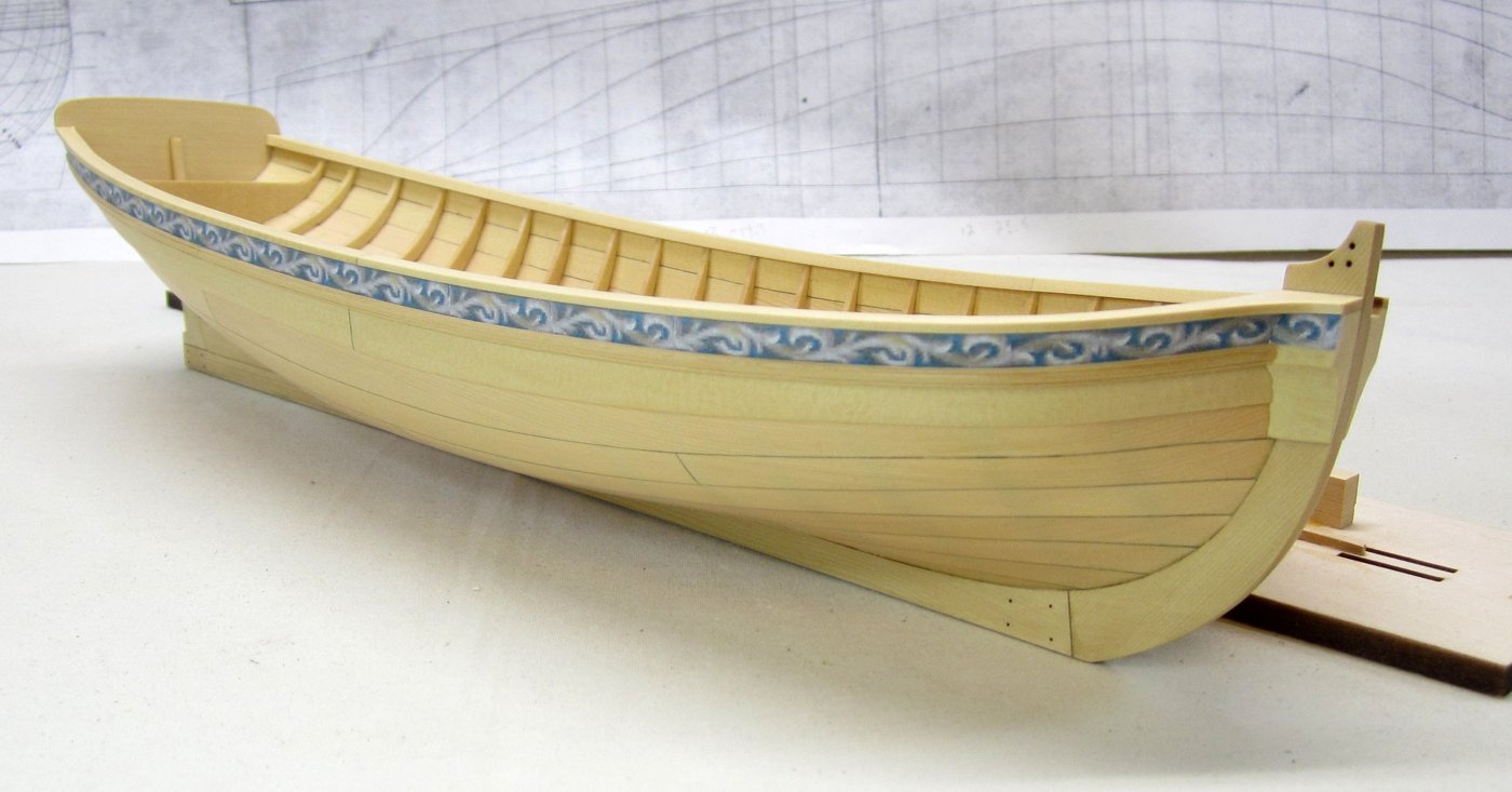
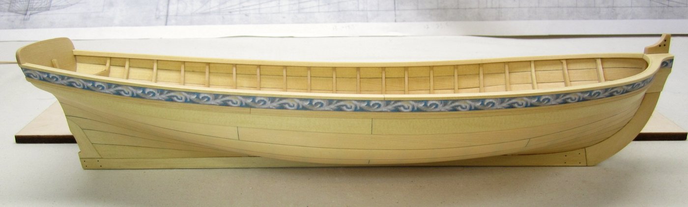
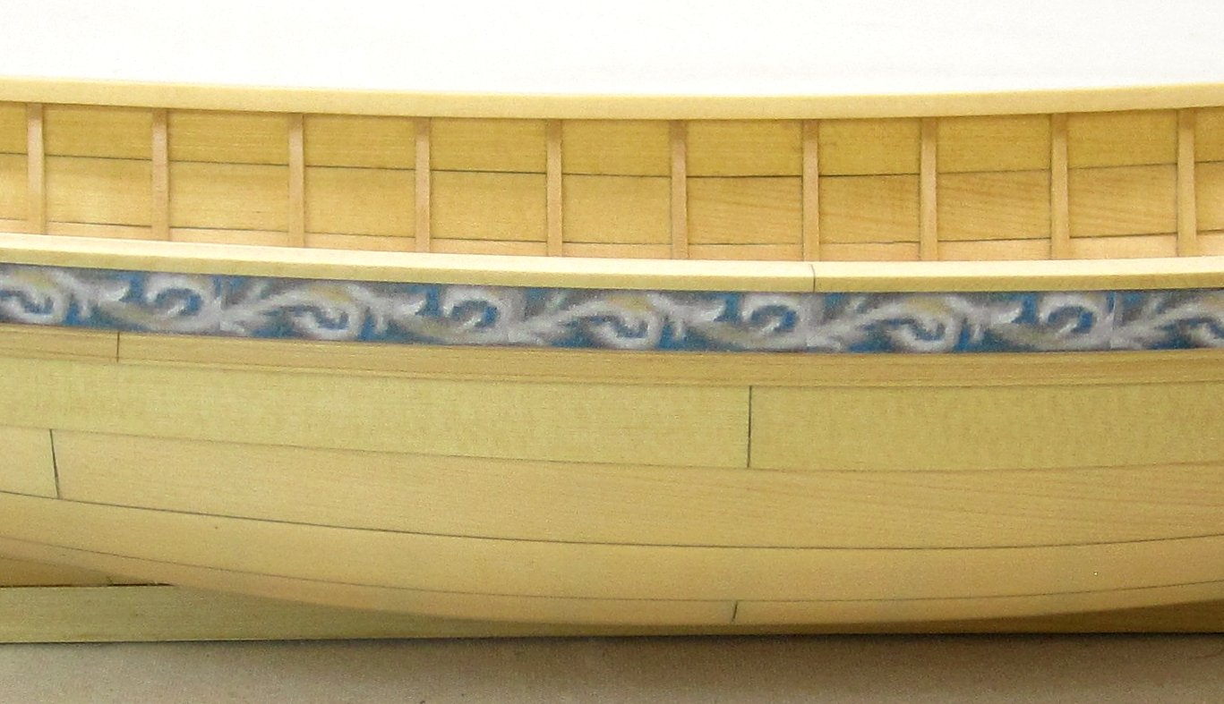
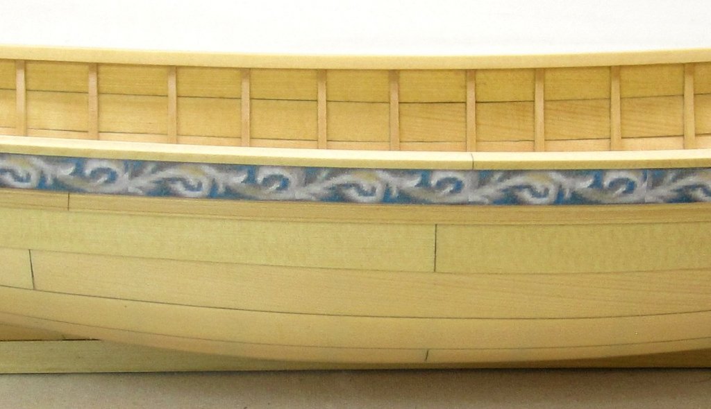
 I added the inboard sheer strip which is also laser cut to shape. It is 1/8" wide and really finishes off the cap rail. Then rather than paint the top of the cap rail red which would have been smart, I decided to work more on the frieze. Once that was added I can use the bottom edge of the frieze to align the molding strip below it. The molding strip is 1/8" x 3/64" and it is scraped to a simple profile. The interesting thing you might note is that the molding strip below the frieze is NOT yellow cedar. The molding is actually boxwood. I find it is the best material for scraping moldings. I will post an illustration of the profile I chose soon. But if you look closely you wont see any real difference in color or appearance in the boxwood strip in comparison with the yellow cedar planking. They work really well together. The frieze itself is an exact copy of the one on the contemporary model. I took the image of the cont. model and cropped and sized the frieze strip from it. After printing it out I went back in and cleaned it up with some paint and color pencils and scanned it again. That was cut out and applied to the model. I am still working on the frieze for the transom.

- 421 replies
-
- 39
-

-

-
- medway longboat
- Syren Ship Model Company
- (and 1 more)
-
I am working on having the package available to build the hull by mid September if everything works out. Then a rigging and masting package will follow after. Chuck
- 421 replies
-
- 17
-
-
-
- medway longboat
- Syren Ship Model Company
- (and 1 more)
-
Same with this one...but there will be no comparison in my opinion.
- 421 replies
-
- 14
-
-
-
- medway longboat
- Syren Ship Model Company
- (and 1 more)
-
No ...I kind of just wing it but I am careful. I take a about a three inch long piece of sandpaper and cup it to a curve when sanding inside. I usually go in one direction only to avoid catching a corner of the sandpaper on a frame. I will sand from each end towards mid-ship...or in this case, mid-boat.
- 421 replies
-
- 6
-
-
- medway longboat
- Syren Ship Model Company
- (and 1 more)
-
Good to know......if you need new frames just let me know which ones.
-
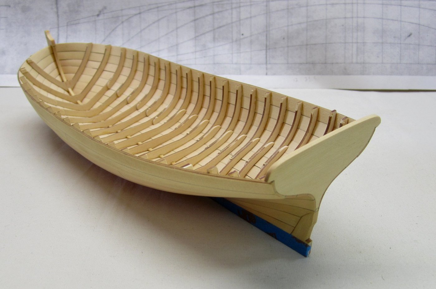
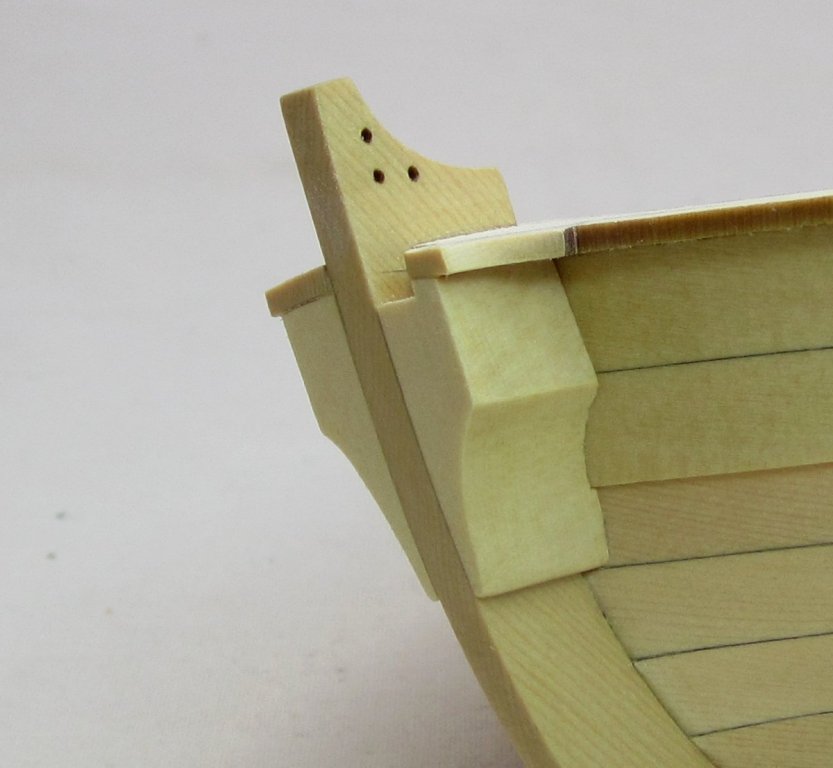
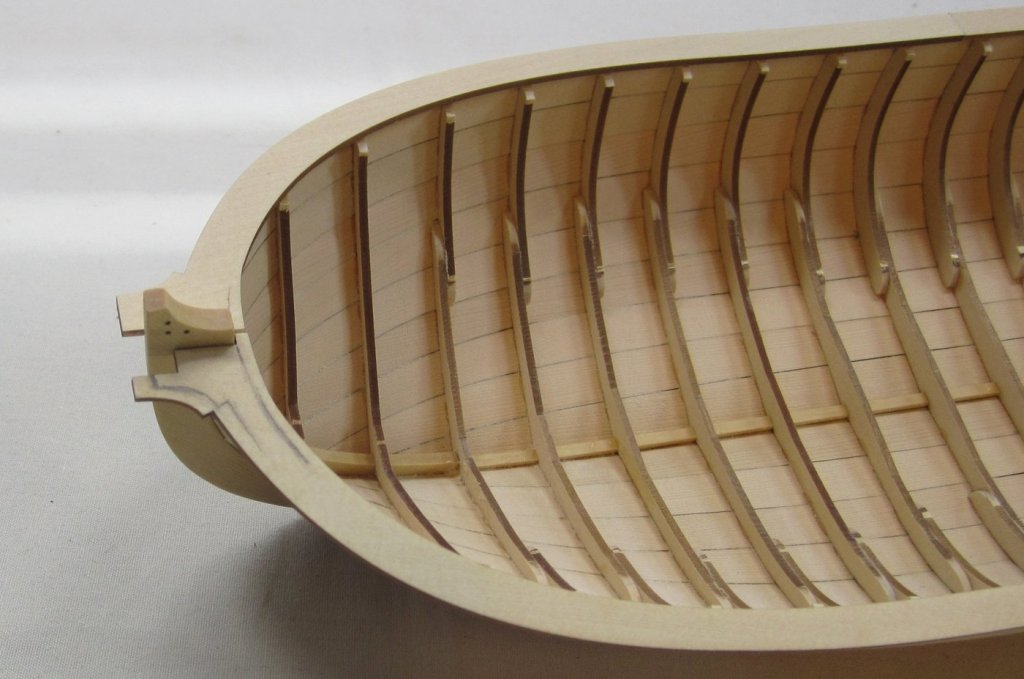
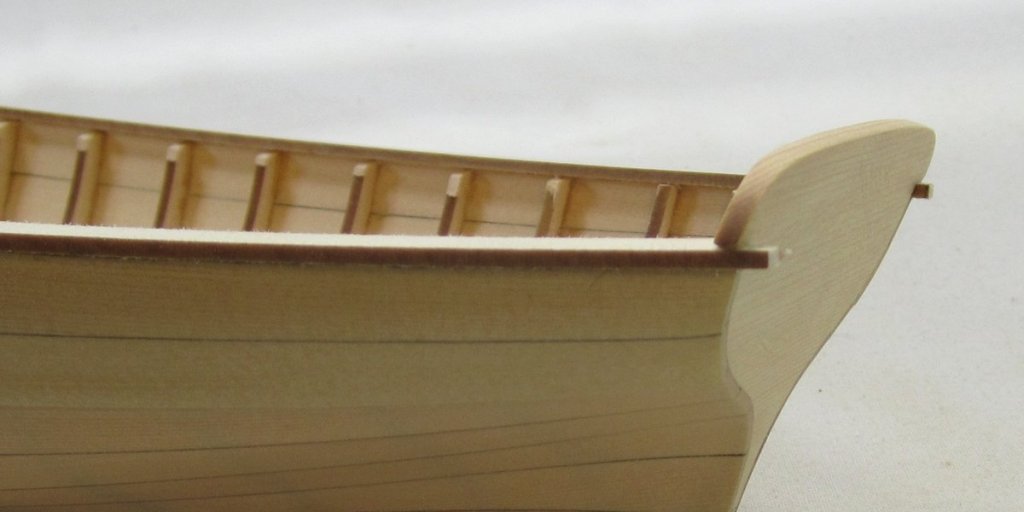
The outboard edge of the caprail was thinned down...it was easier to do this while holding the hull upside down. You want to leave 1/32" overhang with the cap rail. But that is a bit excessive but for now it is good to leave it a bit more. The top of the cap rail will be painted red. I will inevitably get paint on the outside edge which should remain bright, so once the cap rail is painted I will sand it nice and clean and make it less of an overhang. Then it was time to fair inboard which always makes a mess. The goal here is to careful fair the frames so they get gradually thinner as they work their way to the sheer. In our case, the goal is to reduce the cap rail to a minimum width of 5/32". Any wider would look way out of scale. If you can manage a bit narrower that is even better. You can see in the photos what mine looks like and its 5/32" wide. There will be one strake inboard that is 1/32" thick. So that would make the overall width 3/16". So after I install this I will sand it a bit thinner then paint. Then I will sand outboard edge again and the results should leave a cap rail that is just under 3/16" wide. Then the interior was cleaned up a bit and I applied a coat of wipe on poly. You can see the difference in the before and after photo and see how the cap rail was shaped etc....especially at the bow. I used 220 grit sand paper to fair the inside because anything coarser would grab the frames and possibly break them if they werent glued to the planking securely. Slow and steady is the way!!! 😊 Note that the inside edge of the cap rail at the bow is flush with the aft edge of the stem. This is what you are shooting for. The aft edge is sanded flush with the sides of the transom and then the shape of the transom on each side was tweaked to clean everything up. I still have some minor tweaking to do but its just about done and ready for the next step.


- 421 replies
-
- 37
-
-
- medway longboat
- Syren Ship Model Company
- (and 1 more)
-
There is very little CA seepage on the Longboat. Those photos of the frame removal are of the barge. Since that area was going to be covered by a lot of interior planking it didnt need much cleaning up. The longboat however is a different story. I just sand it off. But in fairness there is very little of it as I knew that there wasnt any interior planking. So I was extremely careful. What little was found is just sanded away. It isnt very thick and doesnt stain the wood at all.
- 421 replies
-
- 5
-
-
- medway longboat
- Syren Ship Model Company
- (and 1 more)
-
I am leaning towards that as well!! It also simplifies the build a bit. I think there will be so much going on that it might be a little "kitchen sink" which I dont like. Better to keep it the simple rail and just neatly finish it and paint the top. I can always change my mind and add it later if I dont like it. That will be easy enough. Chuck
- 421 replies
-
- 8
-
-
- medway longboat
- Syren Ship Model Company
- (and 1 more)
-
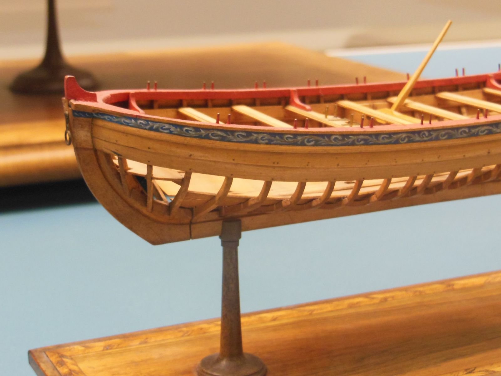
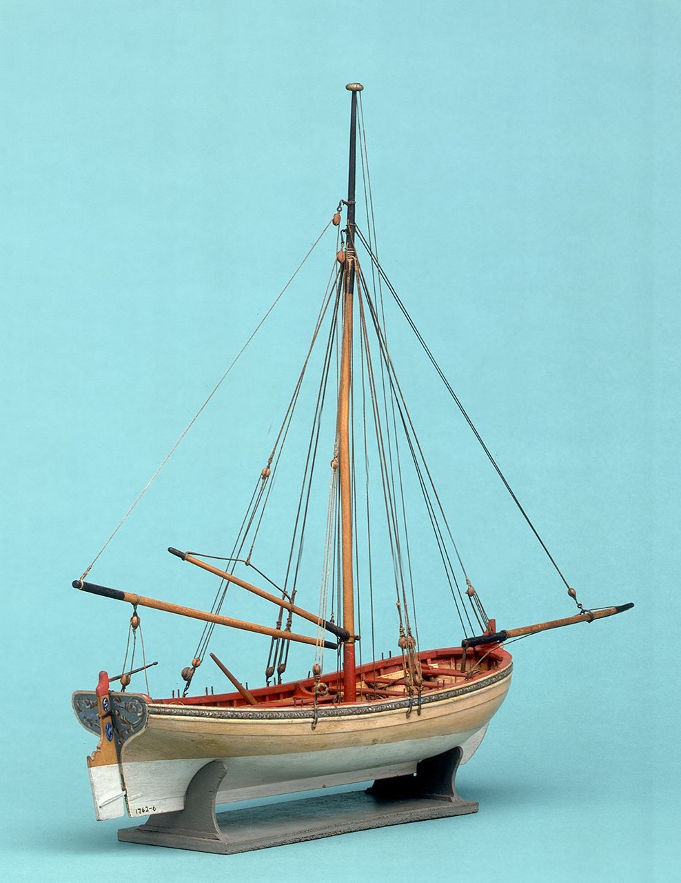
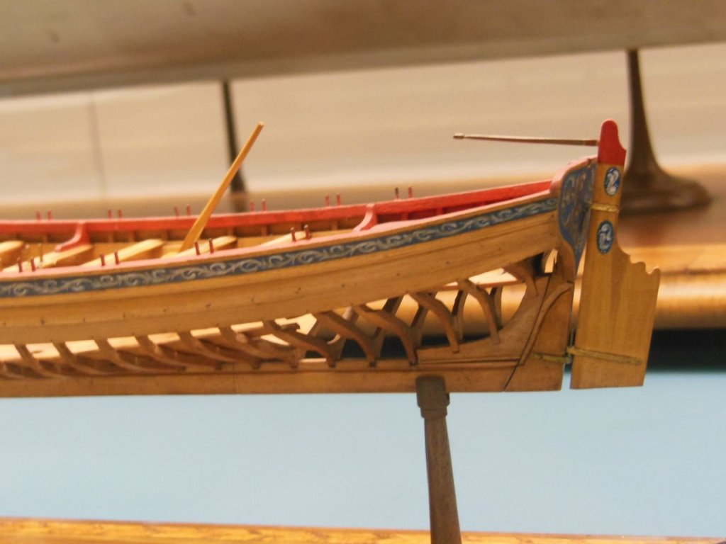
You guys are too much!!! Thanks One thing I wanted to point out because its the next step, is the fact that the contemporary models dont have particularly fancy molding around the cap rail. That is usually the case but in this instance the edge is completely flat actually and hangs just a little over the exterior planking. I have been contemplating if I should follow suit or perhaps add a fancier profile molding. Would it be historically inaccurate and simply a self indulging pleasure? Anyway, what are your thoughts. The molding below the frieze is plenty fancy and wider. Maybe that will be enough. Have to decide now as its the next step. See below for the contemporary version.

- 421 replies
-
- 10
-
-
- medway longboat
- Syren Ship Model Company
- (and 1 more)
-
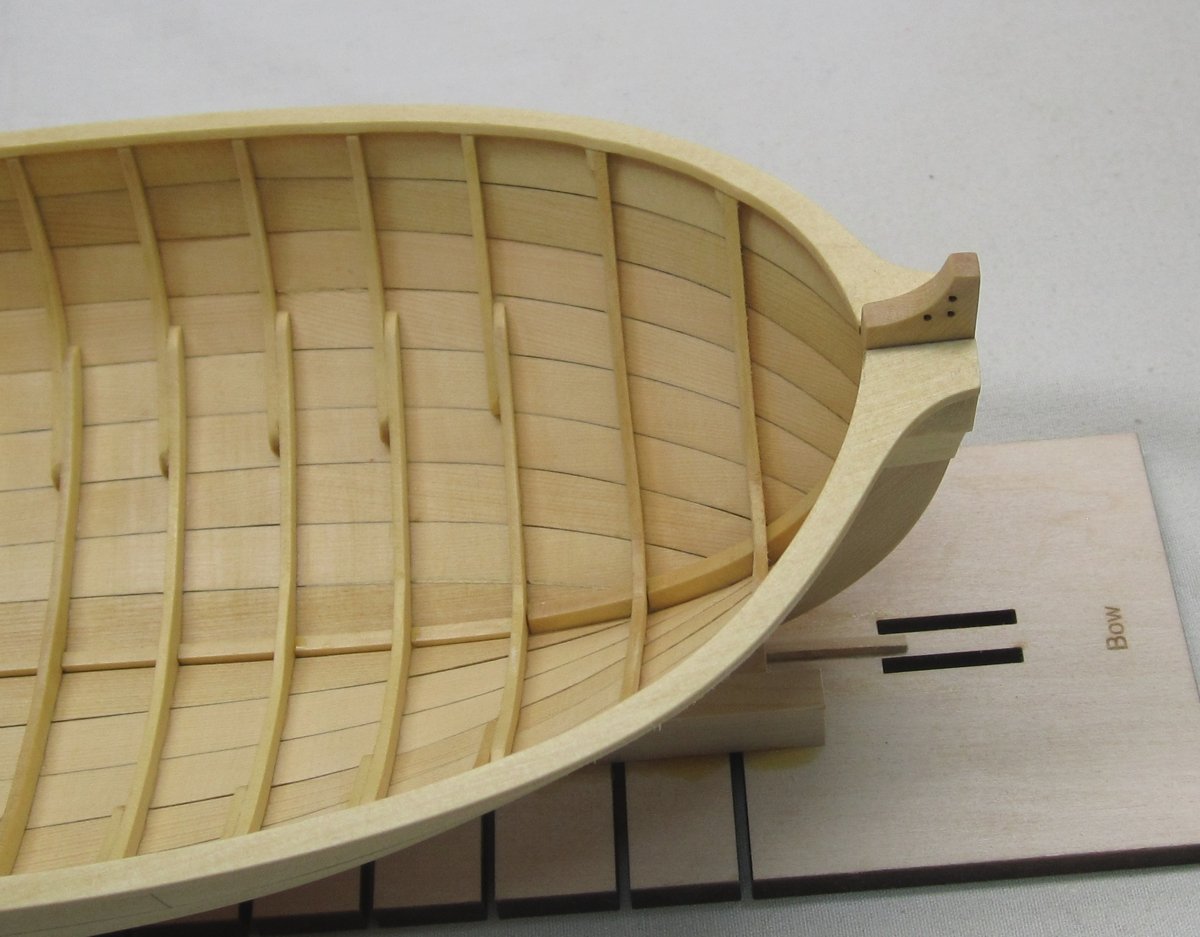
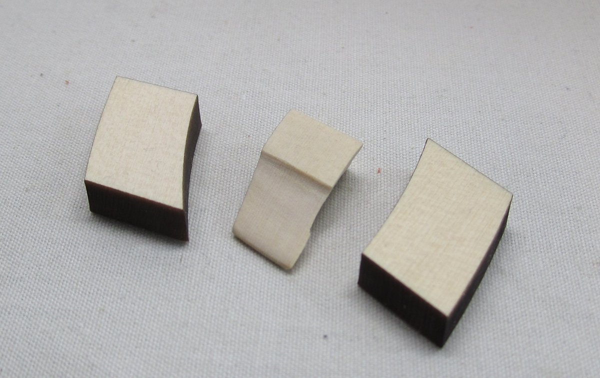
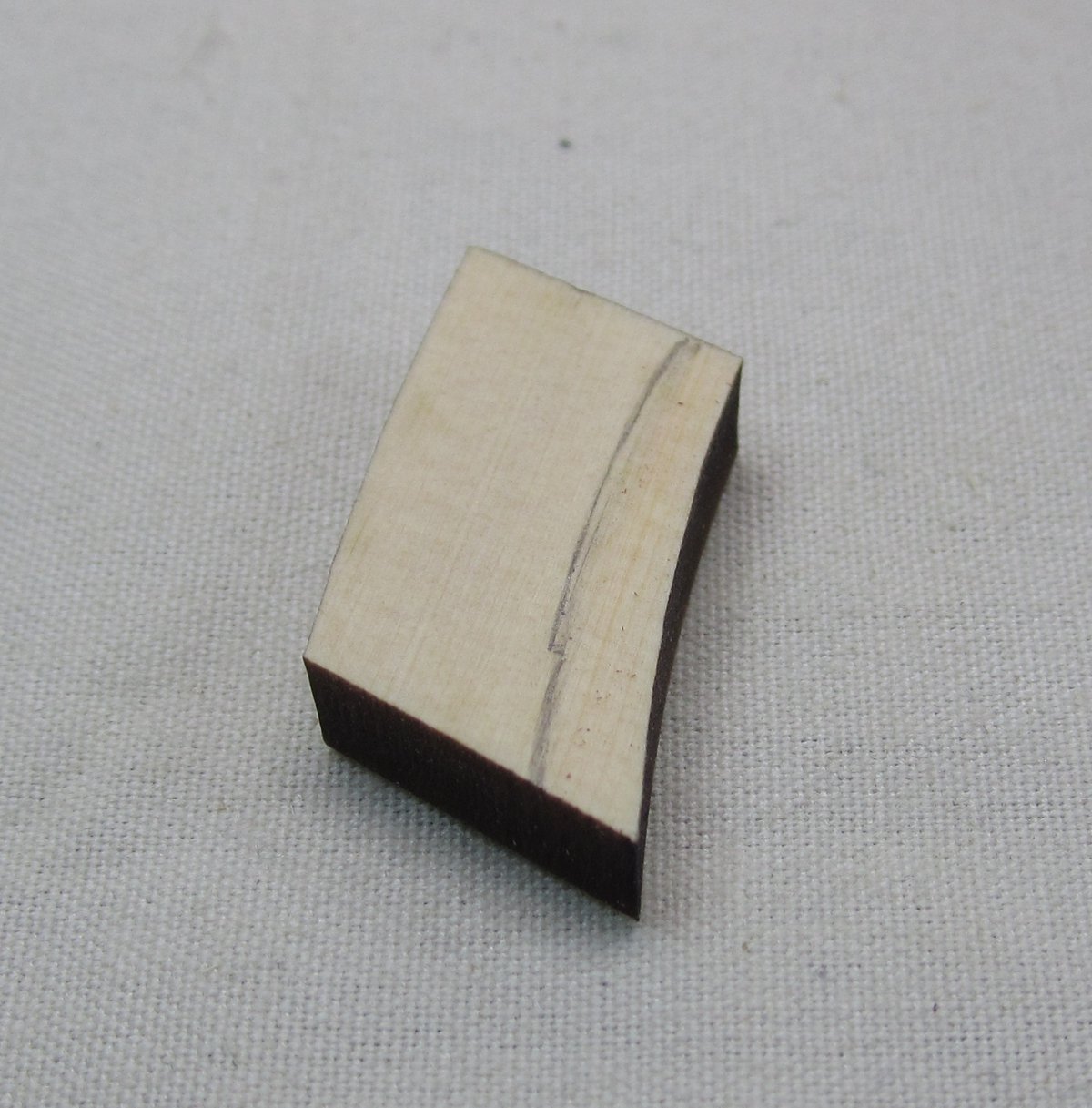
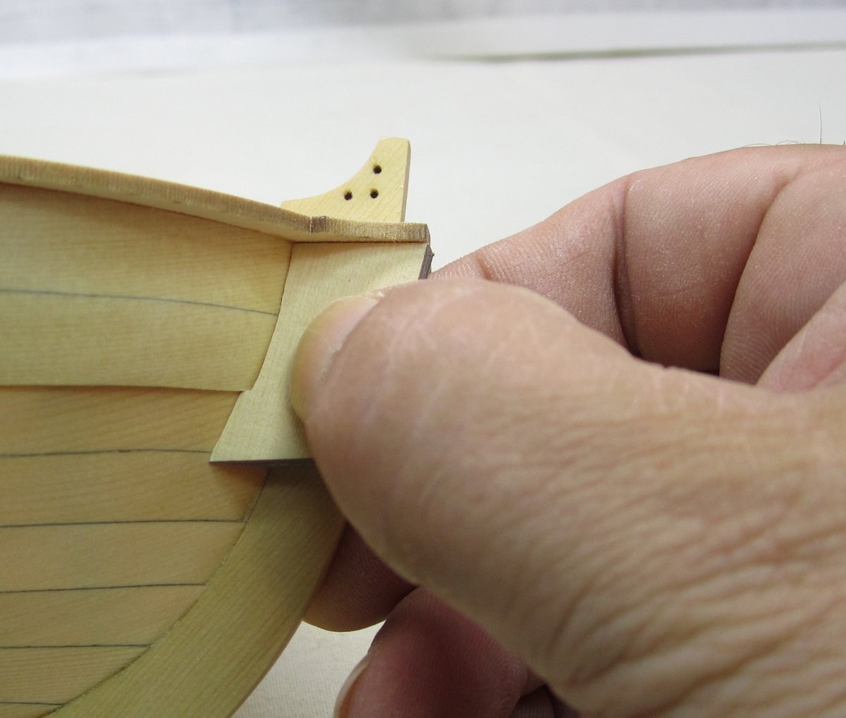
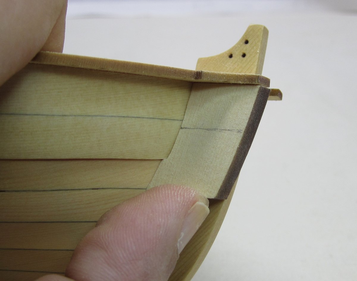
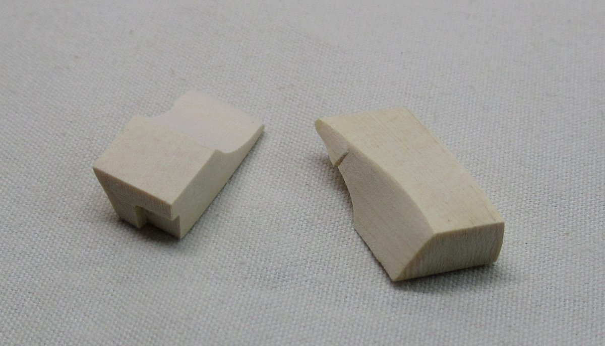
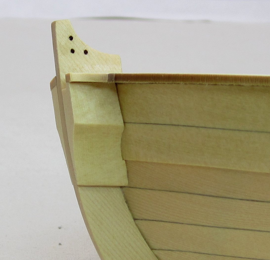
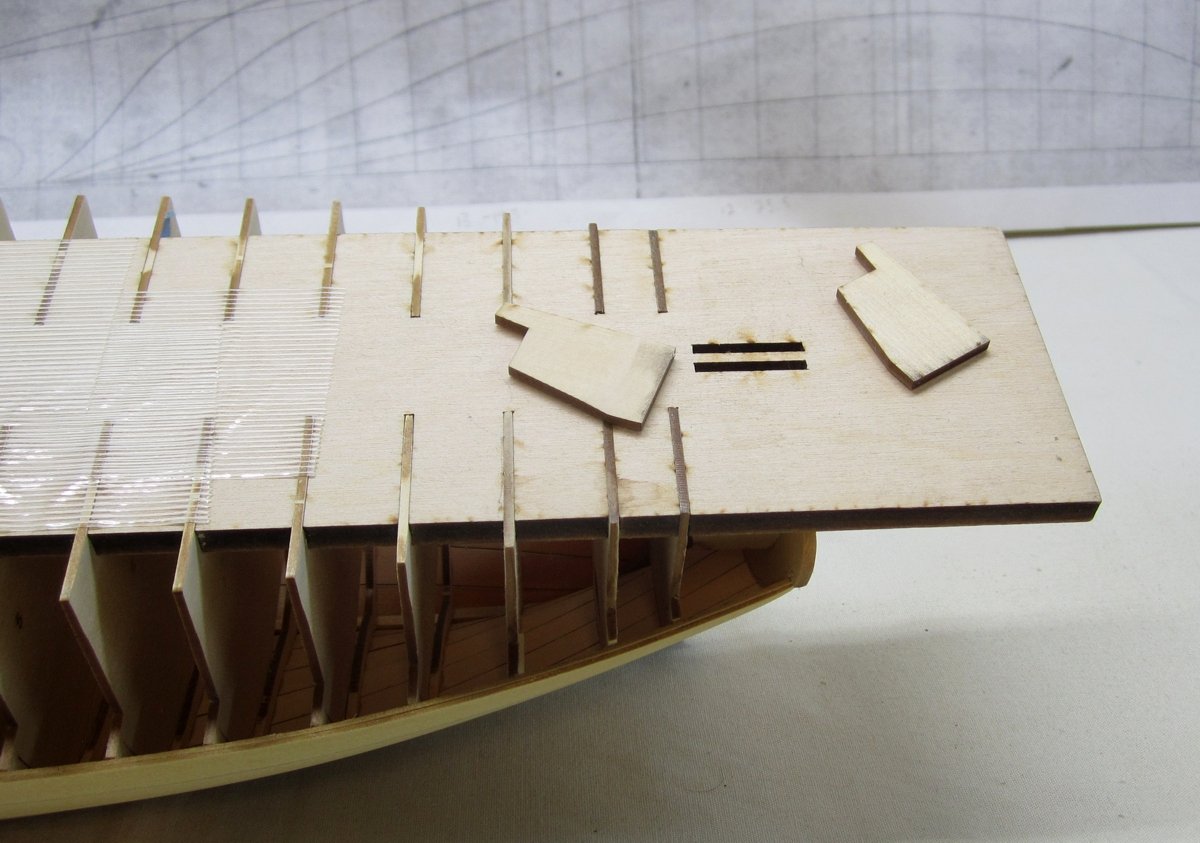
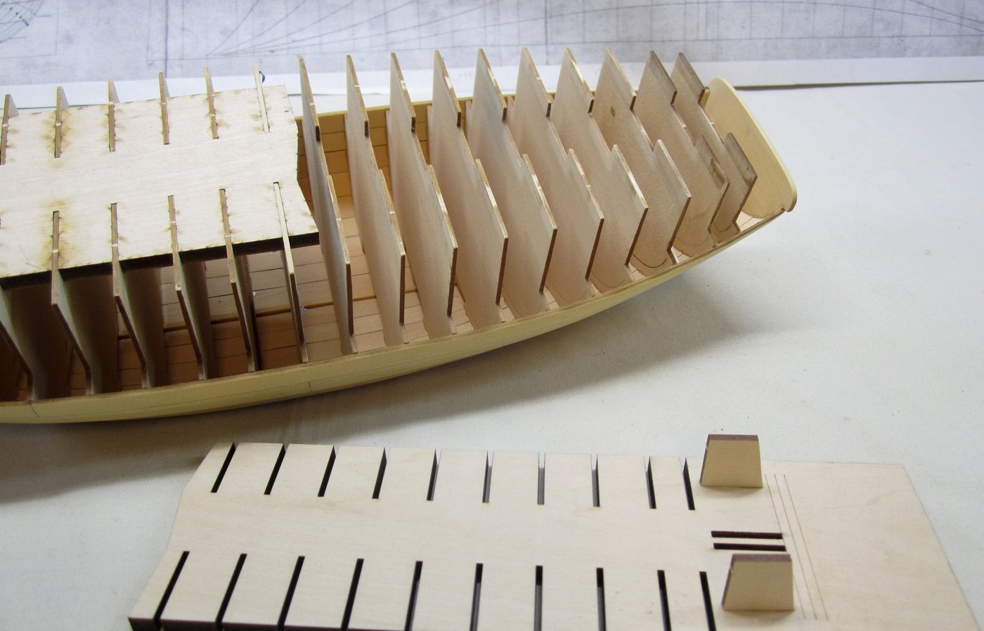
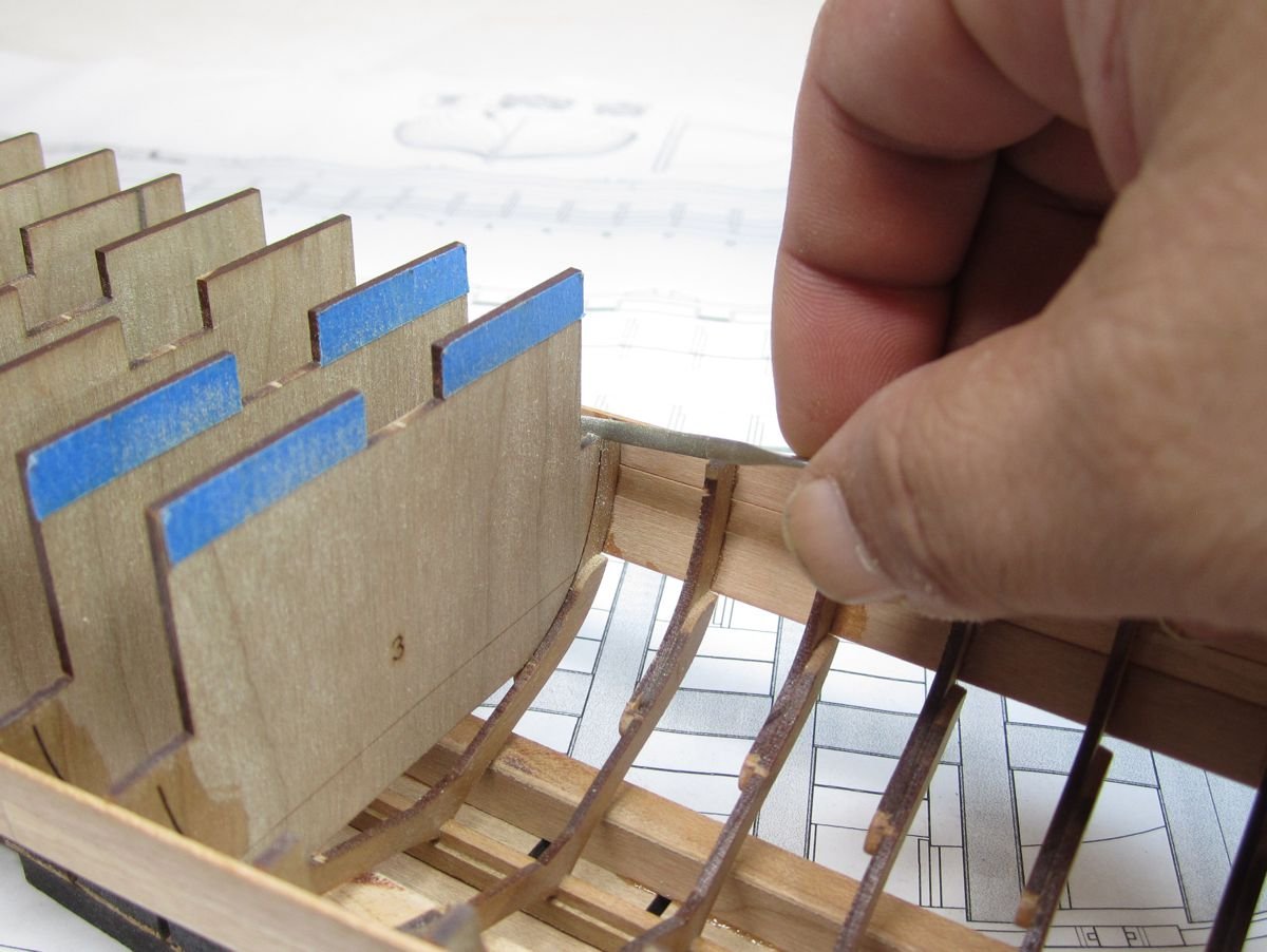
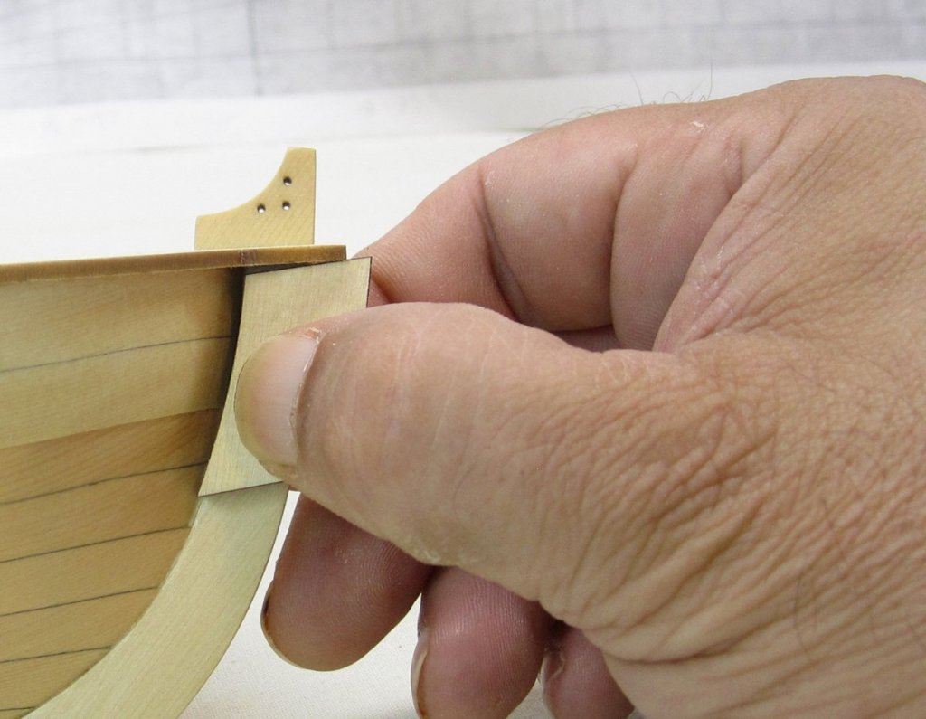
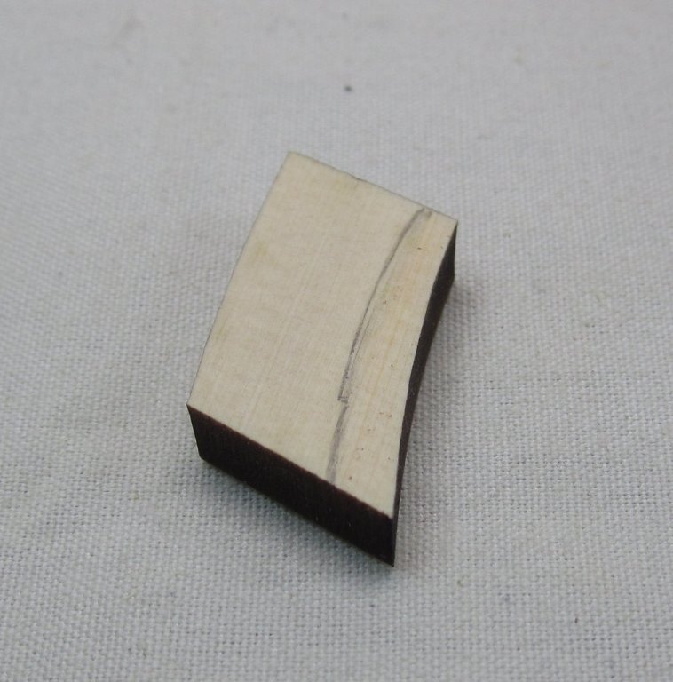
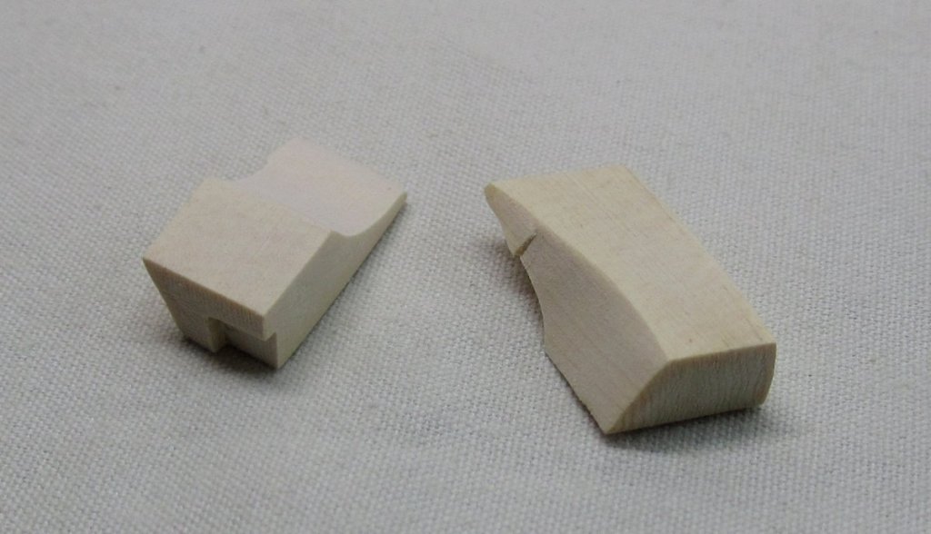
Thanks Dirk, Moving right along, the cap rail was added. It is made of 4 laser cut pieces. They are made over sized and we will thin them down considerably later. A few things worth noting are the cut-away for the roller at the bow. This is on the port side only. So I had to remember to put it on the right side. A 50-50 shot of screwing that up. Anyway, you will notice that I penciled in some reference lines to show everyone what this will eventually be shaped like. But this will happen gradually as we need to take this in steps. There are many details to be added which are easier with an over sized cap rail. At the stern you will notice how the cap rail goes UNDER the wings of the transom. This is important to note as you are planking. There will be a gap between the plank and the transom and that is normal and as designed so the cap rail will fit. It is 1/16" thick. The reason why we cant just start thinning down the cap rail as usual is because this longboat has an interesting feature at the bow we must complete first. Normally we would sand the cap rail flush with the outboard planking. But before we can do that, we have to fabricate the bolsters at the bow. There are two bolsters on each side of the stem. This "beefs" up the stem and helps support the area with the roller. In addition, it strengthens everything up there to help support the bowsprit iron and bowsprit. You can kind of see the bolsters in this photo of the contemporary model. Here is what ours will look like. On every model that I make there are at least one or two parts that are quite a challenge to make. On this model, it will be these bolsters. There are many compound angles to consider. But if you plan it out ahead of time it will go smoothly. You will start with a laser cut blank. Because these parts have the potential for many attempts to end up in the trash....I will provide everyone with eight blanks so you will have plenty of fun. But I will explain step by step how I shaped these bolsters and hopefully it will become clear. First, I recommend starting with the starboard side which has no roller. The blanks are all the same so it doesnt matter which ones you choose. Below you can see that if you hold the blanks against the stem tightly that the aft edge will need to be beveled quite a bit so it sits flush against the hull planking. This is the first thing that you should do and dont worry about any gaps at the top too where the bolster sits under the cap rail. Just concentrate on the getting a snug tight fit against the planking first. I have guestimated the amount of bevel required below by marking it in pencil for you guys. Note how there is more of a bevel towards the bottom of the bolster. I used sand paper and files to create the bevel. I stopped and tested its fit dozens of times as I tweaked it. The photo below shows that its almost there. There is plenty of meat on these blanks so you can sand and reshape quite a bit. So just keep going until it fits good against the planking. Once you are satisfied, You can do the same thing with the top edge and how it fits under the cap rail. It should also be a tight fit here. In the previous photo you can see it fits pretty good without any tweaking. But I will give it a few passes anyway. Next you want to draw in the line that represents the concave shape of the bolster on its outside face. It will taper down to just 1/32" thick at the bottom. This line should follow the run of the sheer and planks. You should place the line even with the bottom of the first plank. I placed mine a bit low in the photo below...so adjust yours to be even with the plank line. Once completed the two bolsters will look like this. And after you create the concave shape you can trim the bottom so it lines up with the bottom of the third plank. Its over-sized and will need to be trimmed. In addition, the front edge will eventually be sanded flush with the stem. But right now it hangs over quite a bit. That is OK. Just deal with shaping them and trimming the bottom edge right now. Note how you will need to make a matching pair of these. The only difference is that a small notch needs to be carved out of the top of the one for the roller. You can see that below. It adds more room for the roller itself. Its shown on the left. Glue them into position and then sand the front face of both flush with the stem. Thats all there is to it......easy-peasy right??? Dont worry its not too bad. JUst go slow and take your time. You will be able to adjust the shape a bit after its glued into position as well. This will make it easier to get a matching pair port and starboard. Dont sand the side of the cap rail yet!!!! Other than the front edge, leave it as is near the bolsters. We will be sanding other parts of the cap rail first.


- 421 replies
-
- 39
-
-
- medway longboat
- Syren Ship Model Company
- (and 1 more)
-
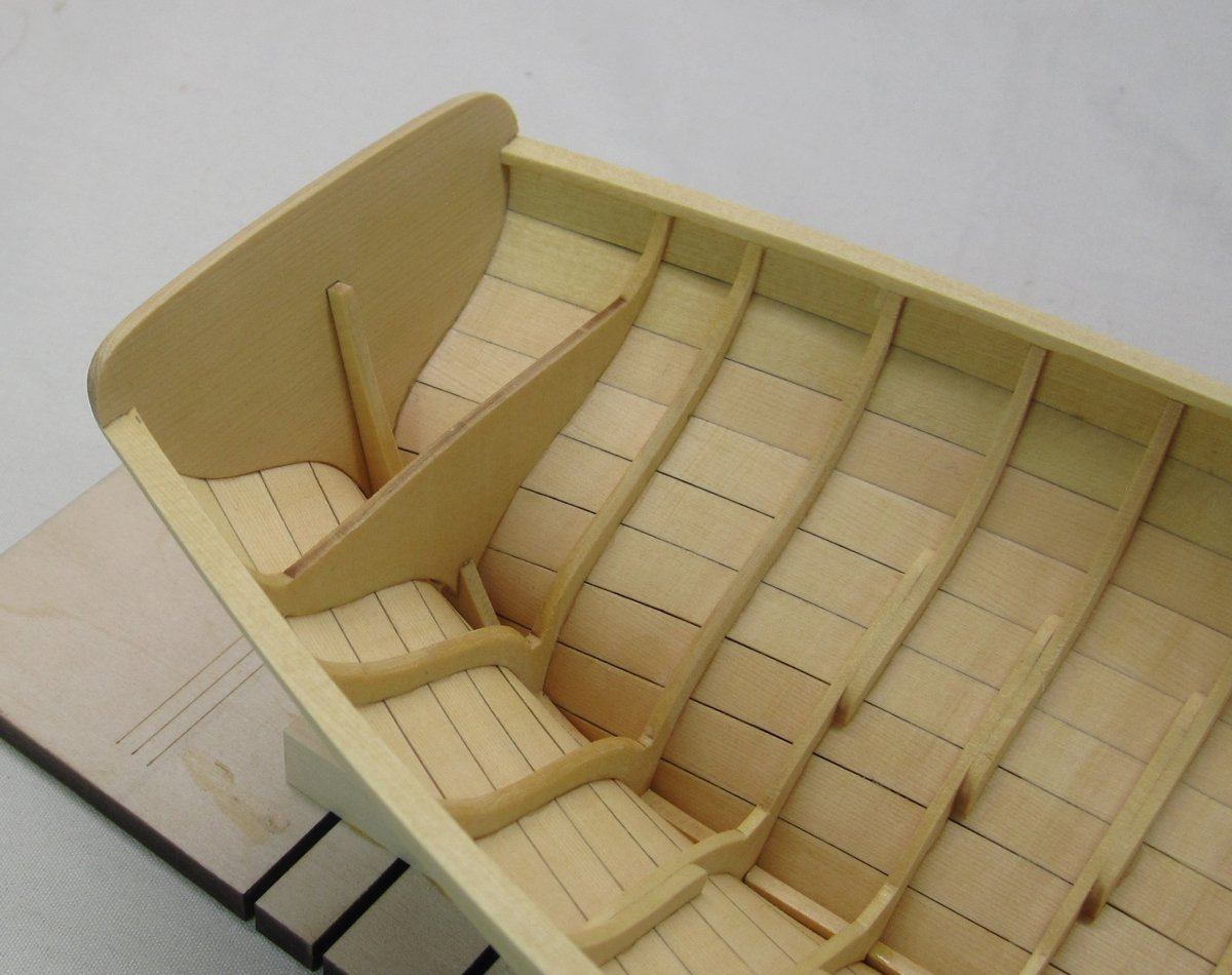
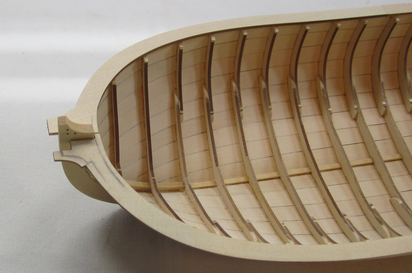
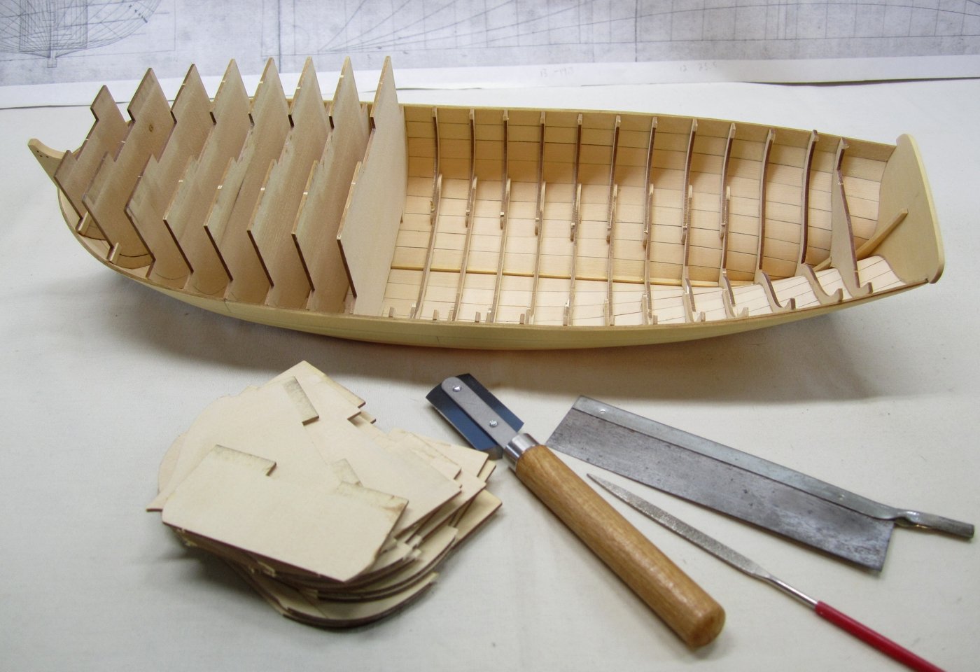
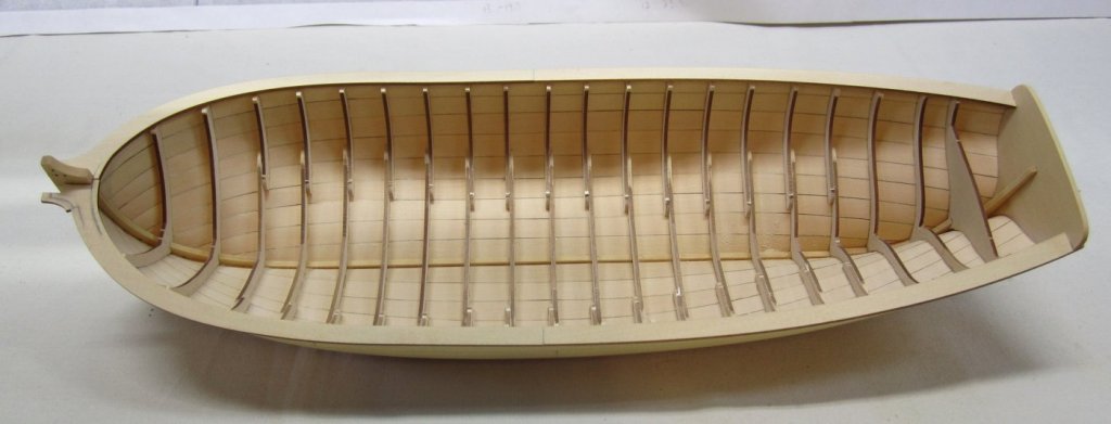
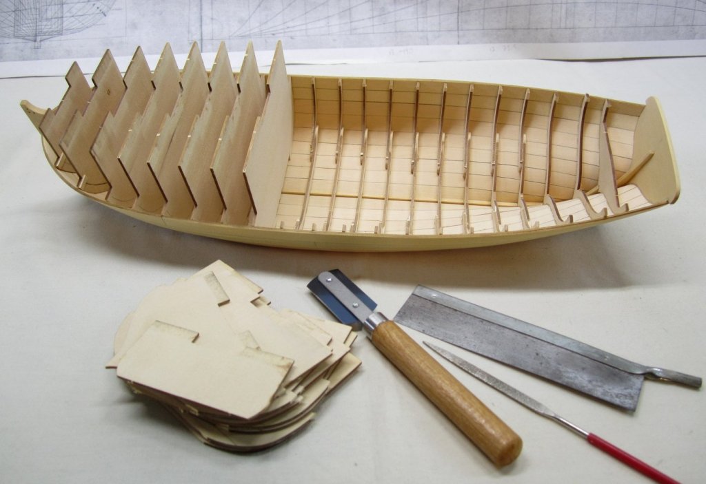
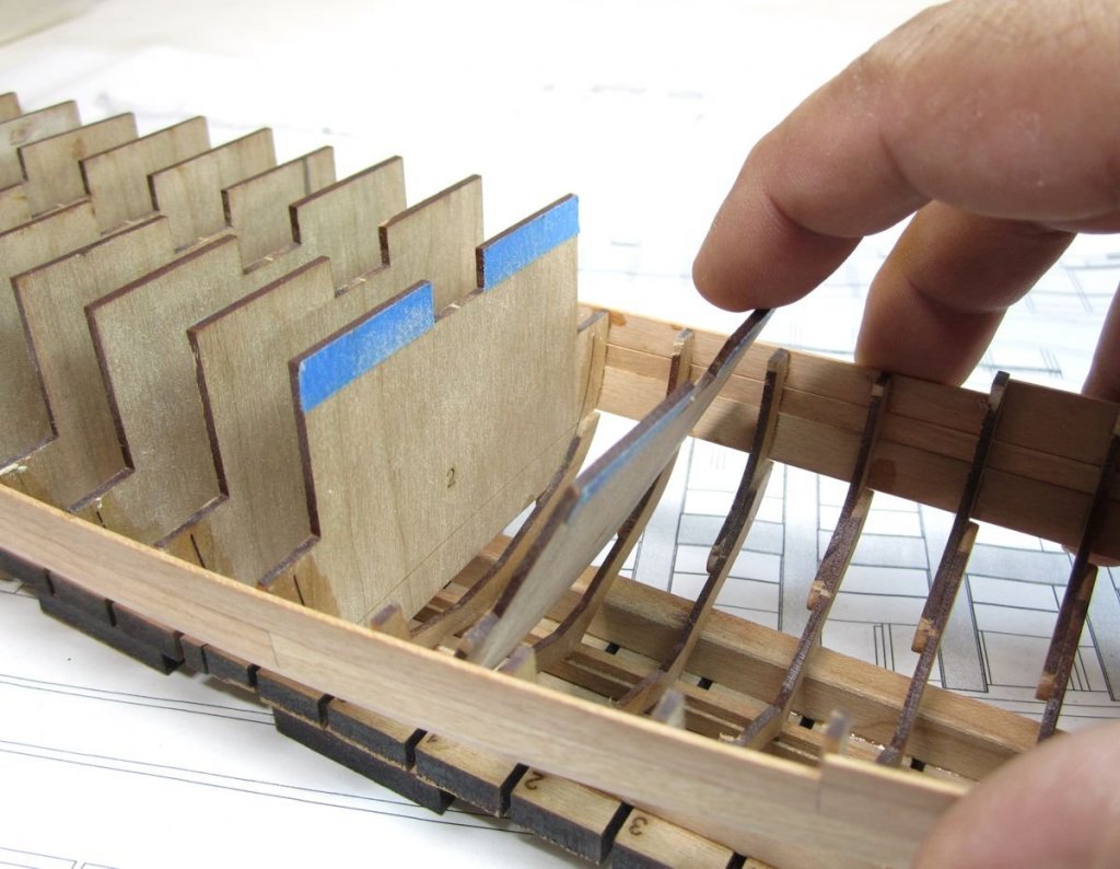
Thank you so much guys. It was time for the fun part.....to remove the buildboard and break away the frame centers. The first step was to remove the braces for the stem and stern post. At the stern post I just pushed them free from the bottom. Then I shook them out. After I removed the tape holding both halves of the buildboard together, I carefully and gently coaxed one half of the buildboard free. Dont rush this and slowly pry it off a little at a time working one side then the other. It will be tricky to get it started especially on a humid day. But once it starts wiggling free it will come off readily. Then using your special tool of choice (everyone has their favorite) you can carefully and slowly cut through the tabs on each side of the frame centers. Then bend them back and forth to snap them out. Do this one at a time. Dont worry about breaking any frames because that will not happen if you have glued the top of your frames securely to the sheer plank. If when you start cutting the tab you see that the entire frame is loose and not secured to the sheer plank, stop and apply some CA. Let it "wick" down to glue the frame to the plank. Then resume cutting that tab. I used the thin saw on the left this time but often use a simple file as well. Whatever you are comfortable with. Here is a shot of a frame center on the barge being removed as I didnt take any of the longboat. Same principle. So I didnt want to duplicate in order save some time. And finally some pictures of the model after removing all of the frame centers. The next step will be fine tuning the sheer. I will sand the tops of the frames flat to the sheer and also sand the sheer so it has a good smooth run. I dont want any dips or high spots. These can be seen by viewing the hull head-on and stern -on at various angles. Once satisfied I will add the caprail which is laser cut. Hopefully over the next day or so. 😊


- 421 replies
-
- 42
-
-
- medway longboat
- Syren Ship Model Company
- (and 1 more)
-
That is correct. I only sometimes when needed do any gluing along the edges. Just in spots if need be. Chuck
- 421 replies
-
- 6
-
-
- medway longboat
- Syren Ship Model Company
- (and 1 more)
-
Yes, its all listed in the wood list. 😊
- 421 replies
-
- 7
-
-
- medway longboat
- Syren Ship Model Company
- (and 1 more)
-
But what is the thickness? Not of the wales but even the general planking topsides. Every Hahn model I see seems so heavy and "thick". It makes the thickness of the bulwarks very wide with a huge cap rail that would probably end up being like two feet wide on the real ship. If I were building the halifax, I would probably use 3/64" thick planking and that would be sanded even thinner once in place. For the wales I would build it up in layers by adding another 3/64" strip on top of it and maybe a thinner one for the black strake. Once the model is done and if done neatly.....who would ever know. I realize that the real ships werent planked like this but its an odd thing to keep trying for "traditions" sake when maybe taking a different approach might be so much less painful and yield better results. If it doesnt effect the final appearance why not give that a try? Chuck
- 421 replies
-
- 15
-
-
- medway longboat
- Syren Ship Model Company
- (and 1 more)
-
How thick was your planking for the wales....It looked so thick and heavy. These planks are just 1/32" thick and bend so easily and conform to the frames nicely. I could never get that result if my plank was 3/32" thick x 3/16" wide. If I had to guess that was the size of the halifax wales correct?
- 421 replies
-
- 5
-
-
- medway longboat
- Syren Ship Model Company
- (and 1 more)
-
I dont clamp my planks. Clamps arent needed ever....it just complicates things and makes it more difficult. At least for me. If you shape your planks properly and pre bend them they should not need any clamps. I take my time tweaking, bending and twisting ahead of time. I will test each and every plank over and over again before I ever glue it into position. Its not something that happens immediately after spiling a plank. Even after having a laser cut plank already shaped, it is close to fitting well..... but never perfect. There may be gaps and high spots because of how I placed the previous plank on the hull. Its an inexact process. There may be slight gaps between it and the previous strake. So I use sandpaper and sanding sticks to bevel a bit more.....or very lightly remove a high spot that might prevent an area next to it from fitting tightly. I will remove just a hair and then retest. I will do this until the plank fits snug against the previous strake all along its length. I may also re bend or re-twist using heat. Then test some more. I could easily spend 45 minutes to an hour on one plank if its giving issues. I may over bevel or over twist and end up screwing it up. So I toss it and make another. For all of my builds I use Titebond exclusively....except for planking. All of my planking is held to the frames with CA. I add a drop or two of CA with a toothpick to just two or three frames being careful to be very neat. Then I glue the plank to those few frames. Then I flex the plank so I can add some more CA to the next two frames...lifting it slightly to reach under it with my toothpick glue applicator....position and press the plank against those frames. I will slowly work my way down the length of the plank a few frames at a time making sure it tightly fits against the previous strake. I just hold it with my fingers for a few seconds and press it flat against the frames. The glue will hold and no forcing is needed, because the shape was good and the twist and bend was good before I started gluing. Hope that makes sense. At times when I have to sand a high spot off the edge of a plank so it fits tightly against the plank already on the hull, I will have to make a mental note to adjust the next strake so I can stay faithful to my tick marks and planking plan that I made while lining out. This is what prevents the run of the planking from getting too waavy or out of wack. Without those tick marks as a guide I would be lost, with or without pre spiled and laser cut planks. I hope this rather lengthy description makes sense. But this is basically my process. No magic just slow and methodical, No special clamping procedure other than my fingers. test ....shape .....then retest....and finally glue. Its hard to describe in writing. One thing I will mention however. I have been watching a lot of people plank hulls over the years. In most cases the planks they are using are way too thick. The thicker the plank the harder it is to glue it into position. I rarely use planking thicker than 3/64" thick. If I need a thicker plank like in this case....I would rather use two layers than try to bend and twist a 1/16" thick strip or a 5/64" thick strip. That is just nuts. I have watched some people try and bend really thick planks for the wales...why in the world does this make sense when after using several layers nobody can ever tell the difference. Like on those Hahn models you are building. I am amazed at the thickness of the wales and you guys try to force one big thick chunk of wood into position with or without pre-bending and twisting. Its something I will never understand.
- 421 replies
-
- 25
-
-
- medway longboat
- Syren Ship Model Company
- (and 1 more)
-
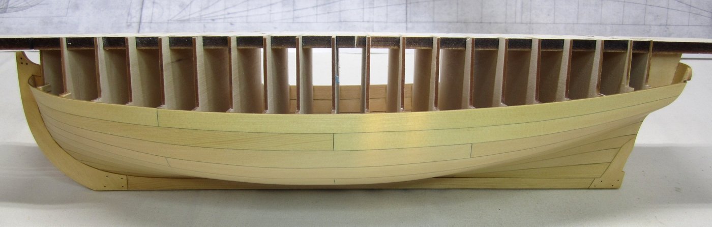
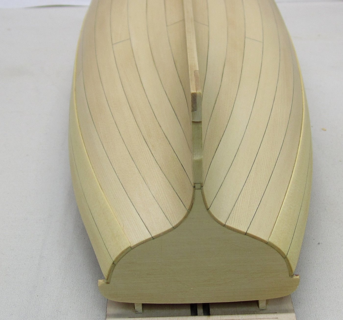
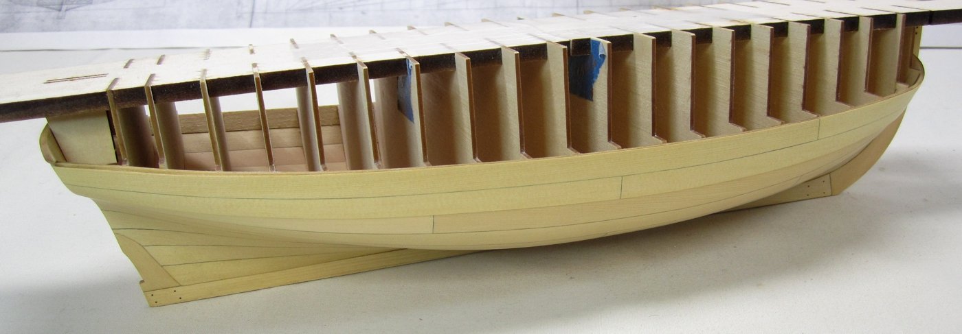
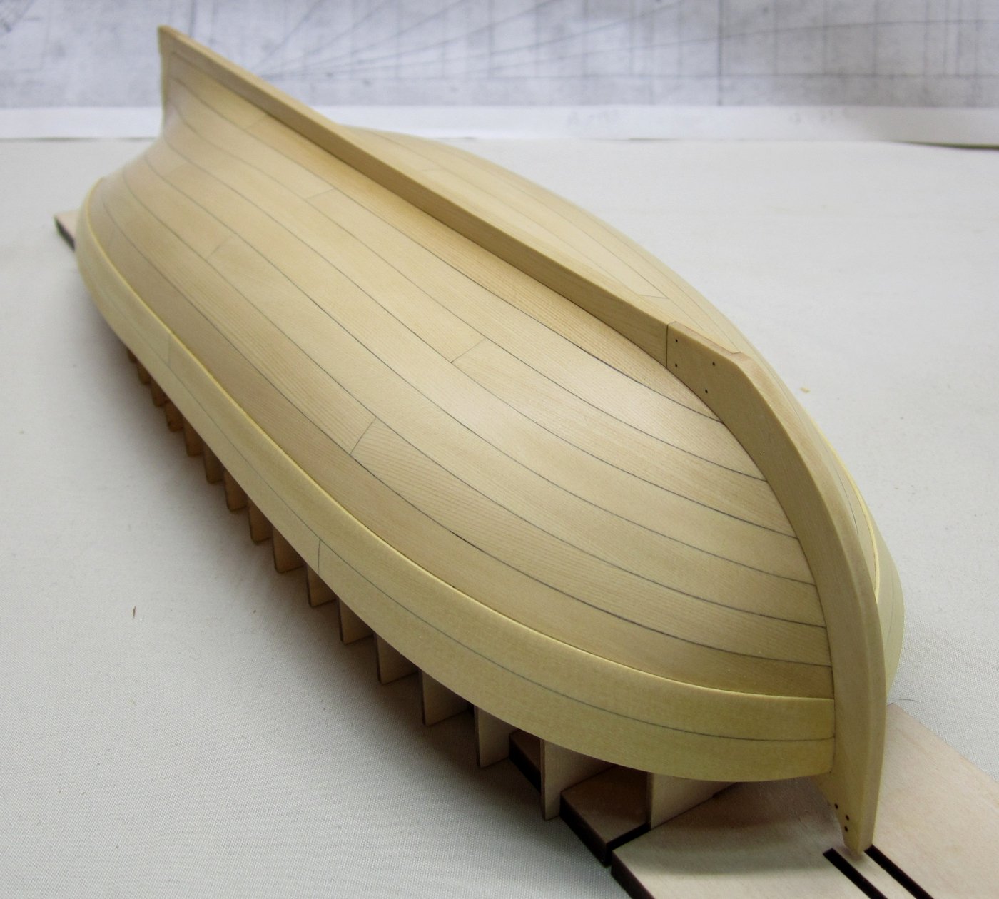
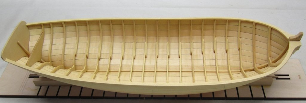
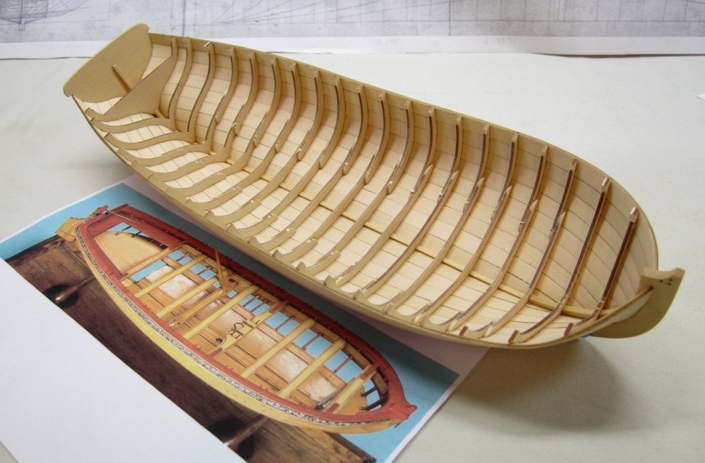
Today was a lazy, hot summer day. I am pretty caught up making rope and blocks so I decided to spend the day finishing the external planking. The last two strakes along the sheer were completed. As mentioned earlier, these are thicker planks than those below them. The second strake being the wales. I contemplated doing these two last strakes several ways. One I thought about was to just use thicker planks. This is a good solution but I kept thinking about some of the guys I know who have trouble bending and twisting heavier planks. The hull is pretty sturdy at this point but being forceful with a heavy plank could be problematic for some, especially if they dont take the time to properly pre-bend and twist it to shape. So in the end I opted for a modelers convention of simplification. Just as I add the wales on my other builds, I decided to use two layers. The 1/32" thick planks bend and twist very easily. This is especially true with the yellow cedar. A second layer of 1/32" planking will be laid right on top of the last two strakes and nobody will be the wiser. Here is the hull with the first layer of planking completed. I was quite happy with the results. Once both sides were done I could see that the port side was less than 1/64" lower at mid ship than the starboard. Nothing that cant be adjusted with the second layer. This is one of the benefits of using a second layer. You can make small adjustments to correct any issues with the ring of your planking at the shear. The second layer is also 1/32" thick. But this is actually slightly thicker than I would like. It is better to sand them down slightly afterwards so they are a bit thinner and not standing so proud of the planks below it. On addition note. At the bow and stern, the planks are actually not thicker. They should gradually reduce in thickness so they are the flush with the planking below them. This is easy enough to do after both strakes are completed. At the stern, I just sanded the last 1/2" of planking so it gradually reduced in thickness and matched the other strakes when viewing the transom head on. You can see this feature on the contemporary model attached. You can also see where I shifted one layer to correct the run. This wont be seen under the painted frieze. The same thing was done at the bow, but I find it easier to use a sharp chisel to slice away the thicker plans along the stem to reduce their thickness. Then I feather that back with some sandpaper so its gradual as it should be. This is all very similar to clinker planking on the barge but we are cheating perhaps and using two layers to simulate the same look. Heres the contemporary model...which is simalar because it was carved and hollowed out from a solid piece of boxwood. The wales and sheer strake were then added as a layer on top of the solid carved hull. Can you imagine basically hollowing out a block until it was thin as an eggshell!!! And one last photo of my hull. All the exterior planking is now complete. I could leave it on the baseboard.....so I could nail the planks (not treenail because they were actual nails). BUT I think it will be easier to do after the cap rail is in position. I also find it hard to see the frames down by the keel now and I dont know where to place my nails. Removing the frame centers and the hull from the baseboard will allow me to hold it up to the light and see the frames clearly. The planks are so thin it is quite easy to do. I will hopefully mark the locations of the frames this way so I dont miss when I drill the holes for the little nails. Hope that makes sense. So tomorrow I will remove it from the baseboard and break-out the frame centers. I have already removed the braces at the bow and the stern that helped hold them stationary. They weren't glued into the slots, so I just popped them out. Even the two center ones at the stern. It will make removing the baseboard easier.


- 421 replies
-
- 38
-
-
- medway longboat
- Syren Ship Model Company
- (and 1 more)
-
Wonderful stuff. Happy to see this model creeping towards the finish line. Question??? How do you plan on getting that model out of the room once completed? Chuck
-
Very nicely done....its a really fun project to build. Enjoy the process and as I have mentioned before....I love to see what all of you guys decide to do with the model. Its a great solid foundation for adding so much more and making it your own unique model... I am actually laser cutting more of these today!!! Chuck
-
Sail design for 18th-century longboat?
Chuck replied to Cathead's topic in Masting, rigging and sails
I dont think so but who knows??? Is it also possible that the tiller wasnt permanent? How feasible would it be for someone to remove the tiller as they swung the boom to the other side and then quickly reposition it into its slot. Just spit-balling. -
Sail design for 18th-century longboat?
Chuck replied to Cathead's topic in Masting, rigging and sails
For all interested and who may also have Mays book on the "boats of men of war". Just turn to page 90. That is all the evidence you will need. It reproduces exactly a sail plan (contemporary draft) that shows the exact rigging arrangement. The prevailing theory is that prior to 1750 or so they used the tiller/sheet arrangement shown on the model. It doesnt make sense but it is 100% accurate for the time period. And yes the fixed block on the stem is for the outhaul. I dont understand why it isnt rigged that way on teh contemporary model. One end is fixed to the traveler ring and then run through a sheave in the end of the bowsprit. Then its taken through the fixed block and belayed inboard to a thwart. There is other contemporary evidence of this. -
Wood Project source is no longer in business. They just havent taken the website down yet. For really great maple stock. Use http://www.ocoochhardwoods.com Just send them an email with the list of thicknesses you need if they arent shown in their store. The wood is very good. Great prices. I wont offer Cherry or Maple because this guy and a few others like National Balsa offer great product at prices I cant compete with in teh US. Just an FYI. Chuck
-
That looks great Rusty. The flags look very good. One thing I would suggest is that in the future, its better to cut the dolphins for the sweeps by cutting close around the dolphin itself. Then you wont see the paper at all. Then run your red paint along the edge of the dolphins to cover the white paper edge. Chuck
- 120 replies
-
- 6
-
-
- queen anne barge
- Syren Ship Model Company
- (and 1 more)
-
No not yet. I figured most would want to fully plank. But I could be wrong. I may do that version in swiss pear also so I havent decided yet.
- 421 replies
-
- 2
-
-
- medway longboat
- Syren Ship Model Company
- (and 1 more)