


gak1965
-
Posts
698 -
Joined
-
Last visited
Content Type
Profiles
Forums
Gallery
Events
Posts posted by gak1965
-
-
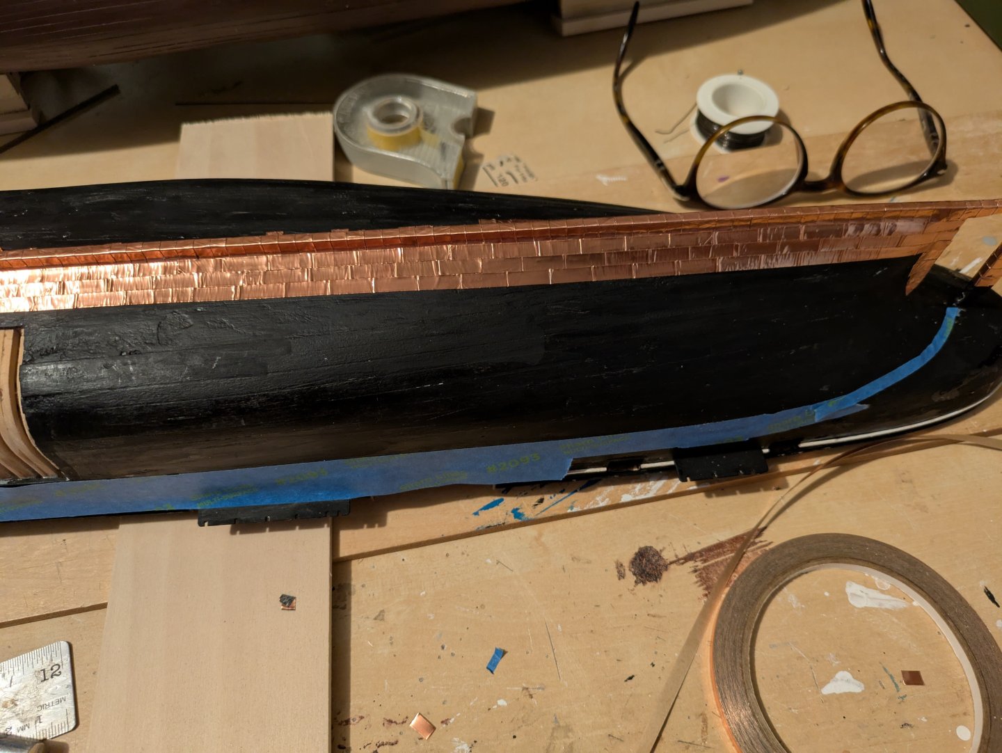
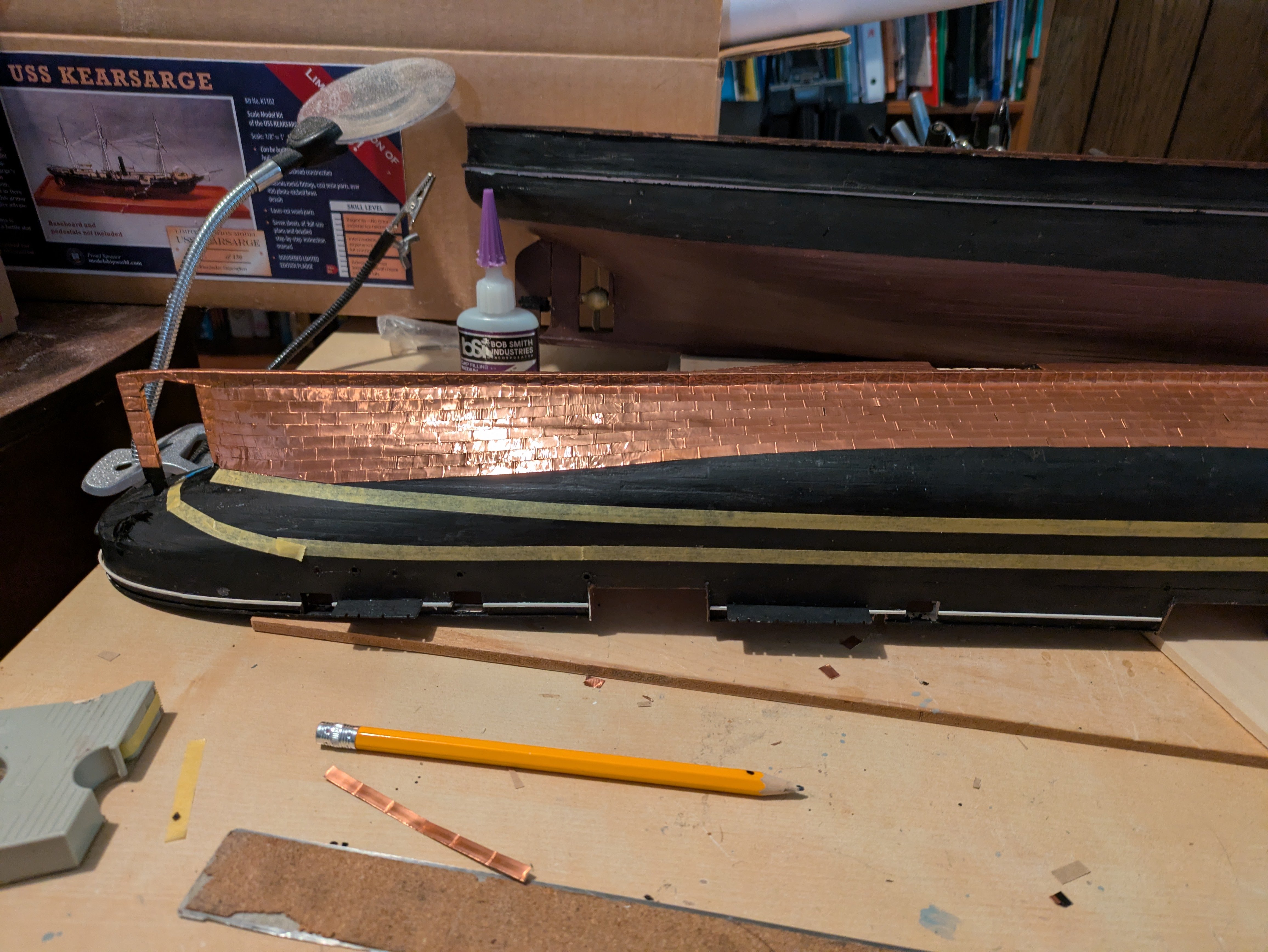
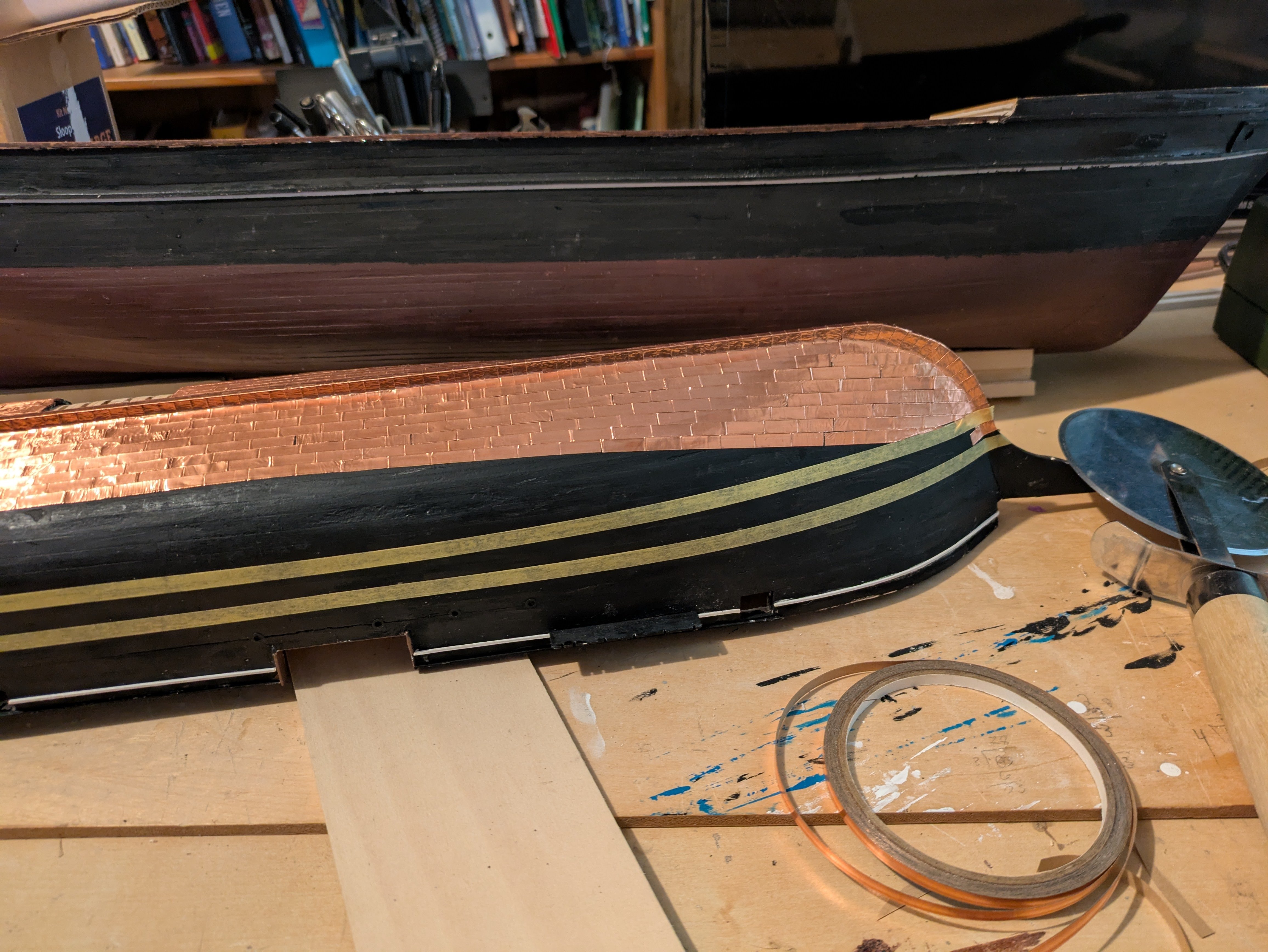
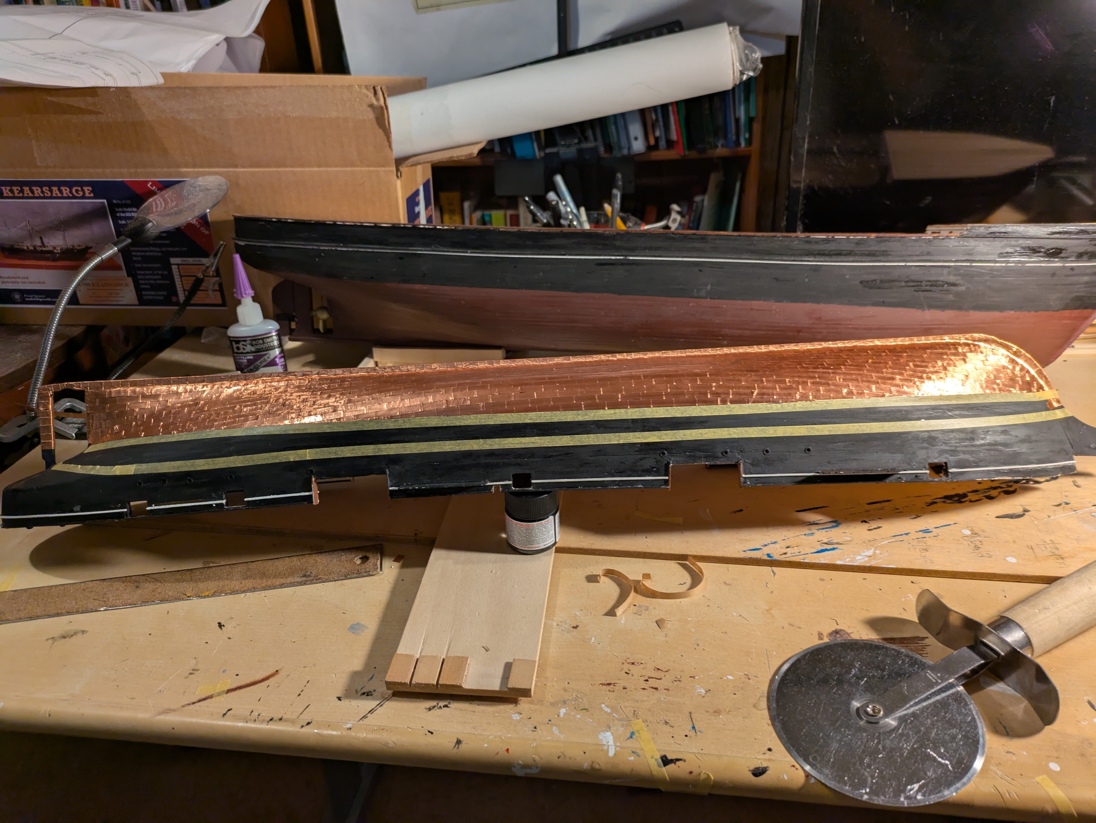
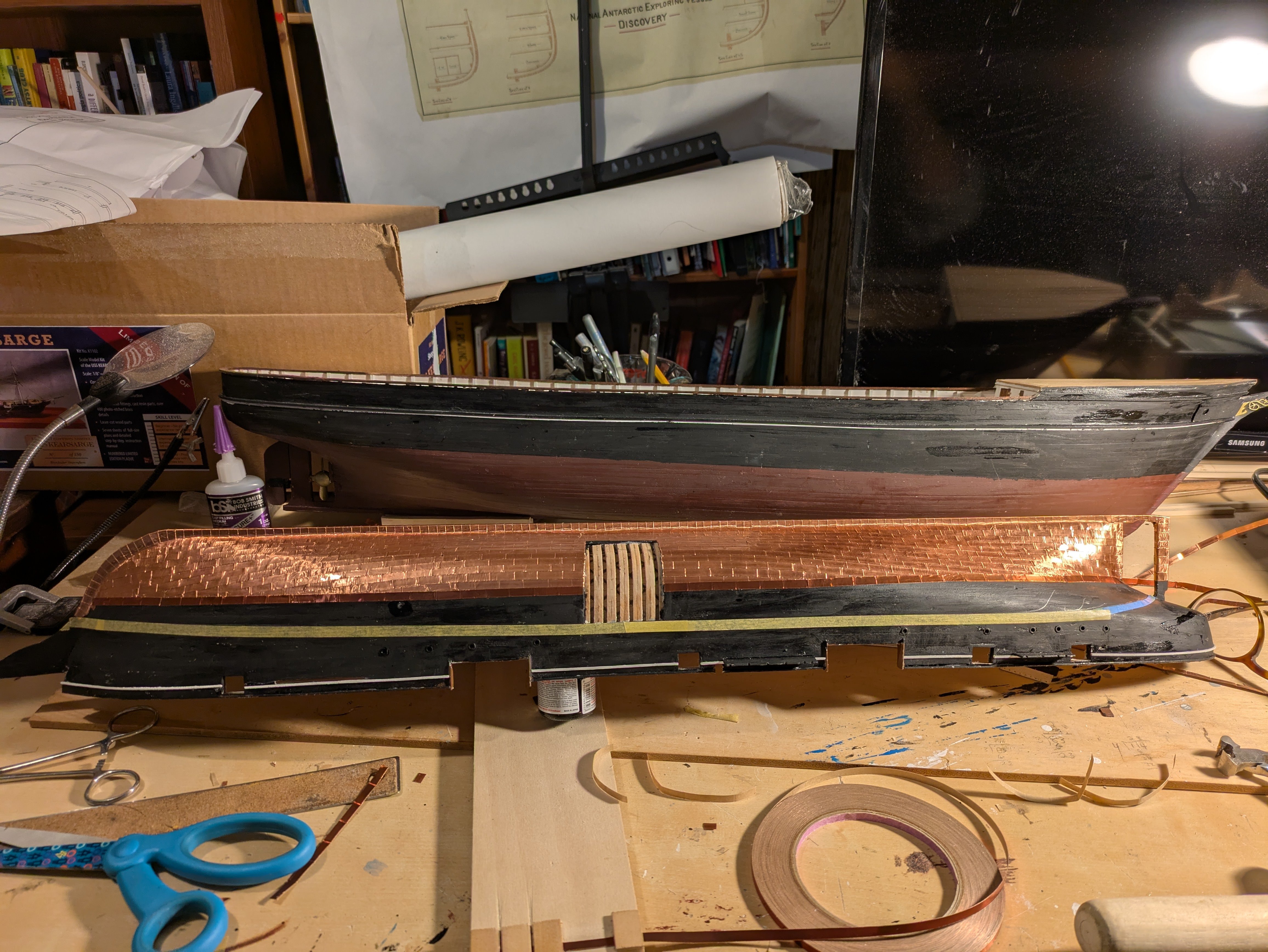
Copper plating continues. The first picture shows the plating before I was really reaching the gore line:

As the plating was "bending" up at the stem and stern, it was terminated at the tape marked gore line, where I will start a new row of plating that is more in line with the final waterline. Here it is at the stern:

and the stem:

The next two show the plates up to the gore line with the tape still in place:

And removed
Finally, here is the first of the plates above the gore line:

One thing that surprised me was that I started a new roll of Venture tape when I went to the gore line and it seems a bit redder to me. I doubt that it will matter once it tarnishes a bit, but it was still a surprise. Fortunately, I ran out of the old roll just as I finished both sides below the gore line, so it will at least be consistent. If it really starts bothering me, I can hit it with some copper paint, but, like I said, my guess is once it starts tarnishing it won't be very obvious.
Regards,
George
- schooner, Canute, JacquesCousteau and 4 others
-
 7
7
-
Looking great, Jared!
-
3 hours ago, Jared said:
Thanks for the suggestions. The lines that I am concerned about are some of the stays, which are starting to sag as you can see in the attached photo.
Jared,
Is it only the forestays, or are you seeing other stays sag a bit as well? If it's just the forestays, did something happen to the bowsprit or the dolphin striker? That seems more likely than the foremast starting to bend forward to any degree.
-
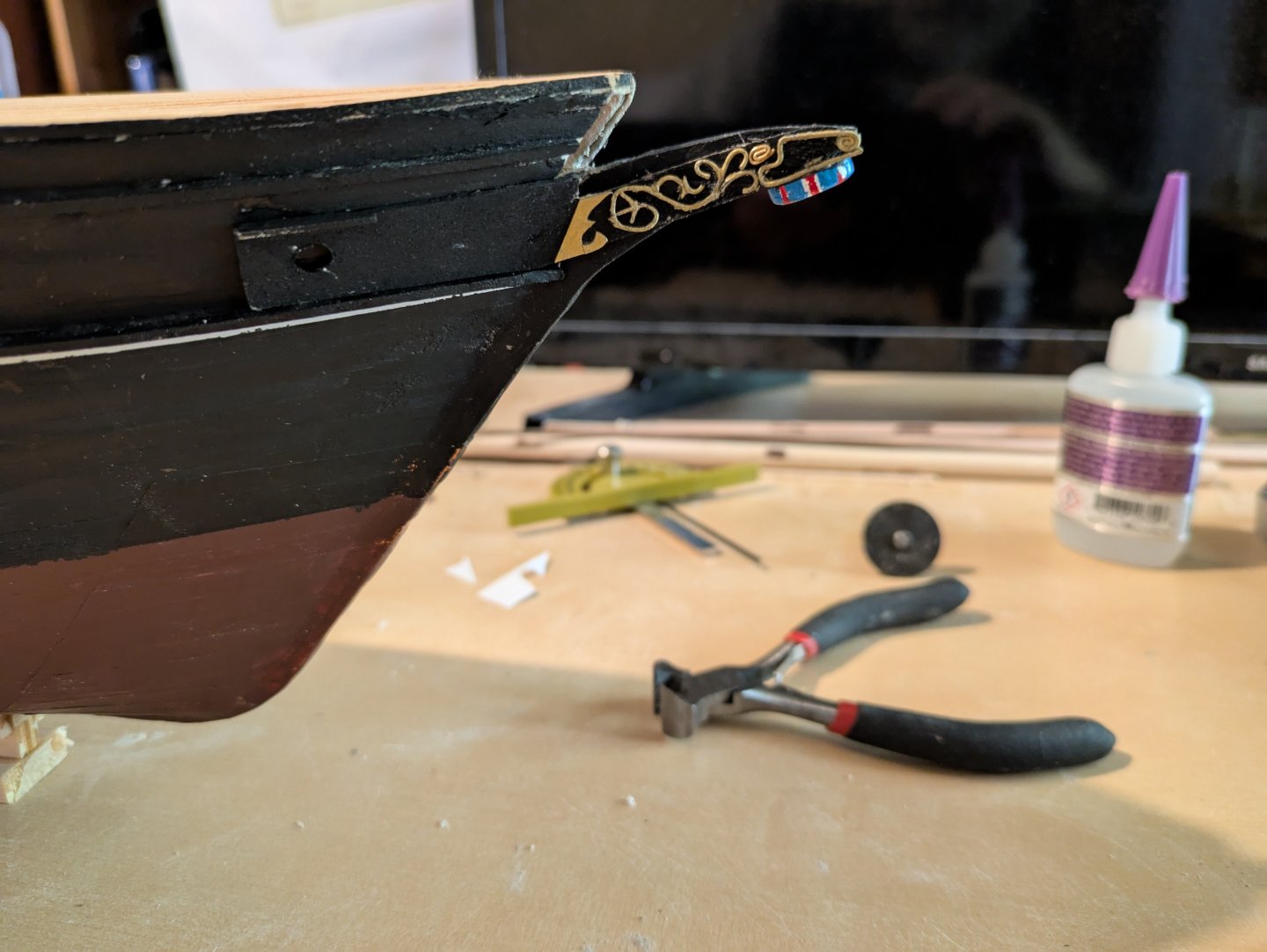
Okay, it's been a couple of months where I've been mostly focused on the Discovery. Here she is now, including the bow decoration which was a royal pain to make:

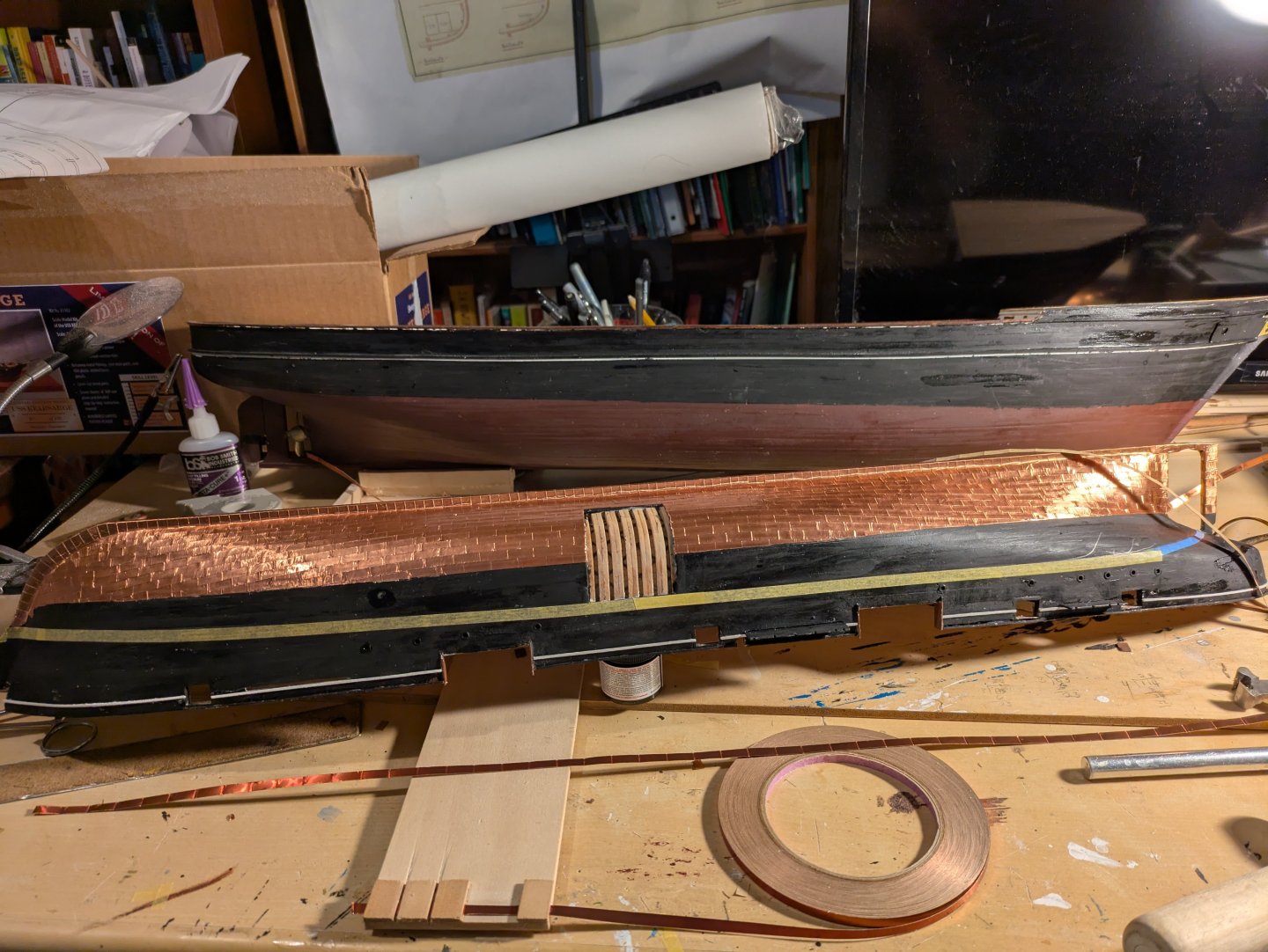
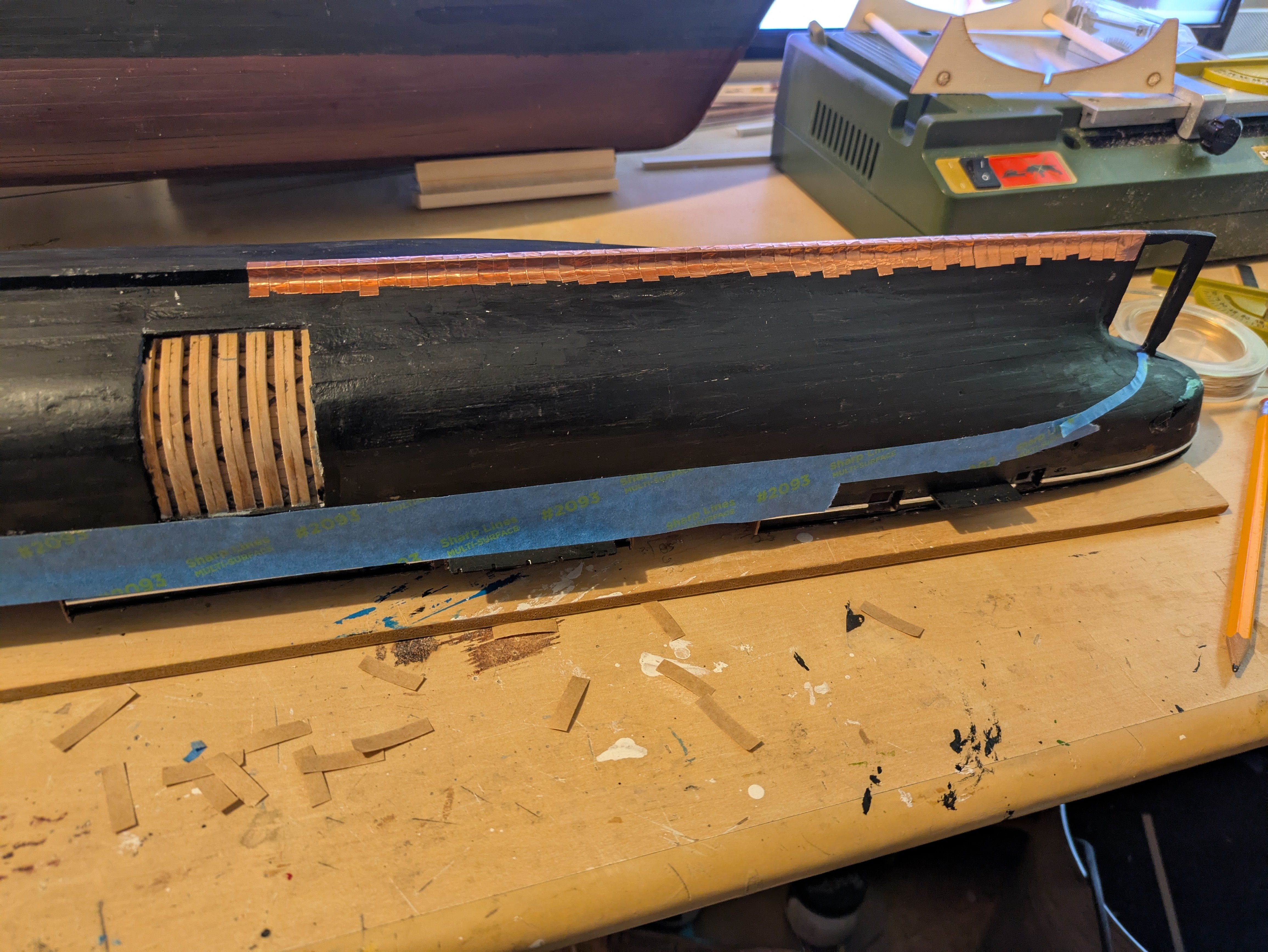
So, back to the Kearsarge for a bit. As I indicated above, next is going to be the copper plating, after which, I can mount on a build board. I like to use 3/16 venture tape, which is now discontinued, for making plates at 1:96 scale. I also like to make them about 1/2" long, which translates to a 18" by 48" plate in real life. The Flying Fish called for 14" high plates, looking at some of the ones on the Constitution makes me thank that this is close enough. So, step 1 is to put copper tape on the keel and at the stem and stern to sort of frame the bulk of the copper work. I have a batch of 1/4" Venture tape that I used for that. Obviously I wasn't going for precision, but it won't matter, because, except on the actual keel, it will be covered by the rows of plates. The blue tape marks the point where I will stop coppering.

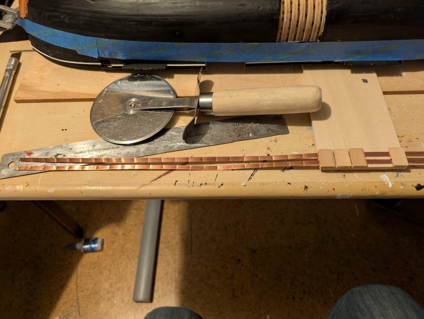
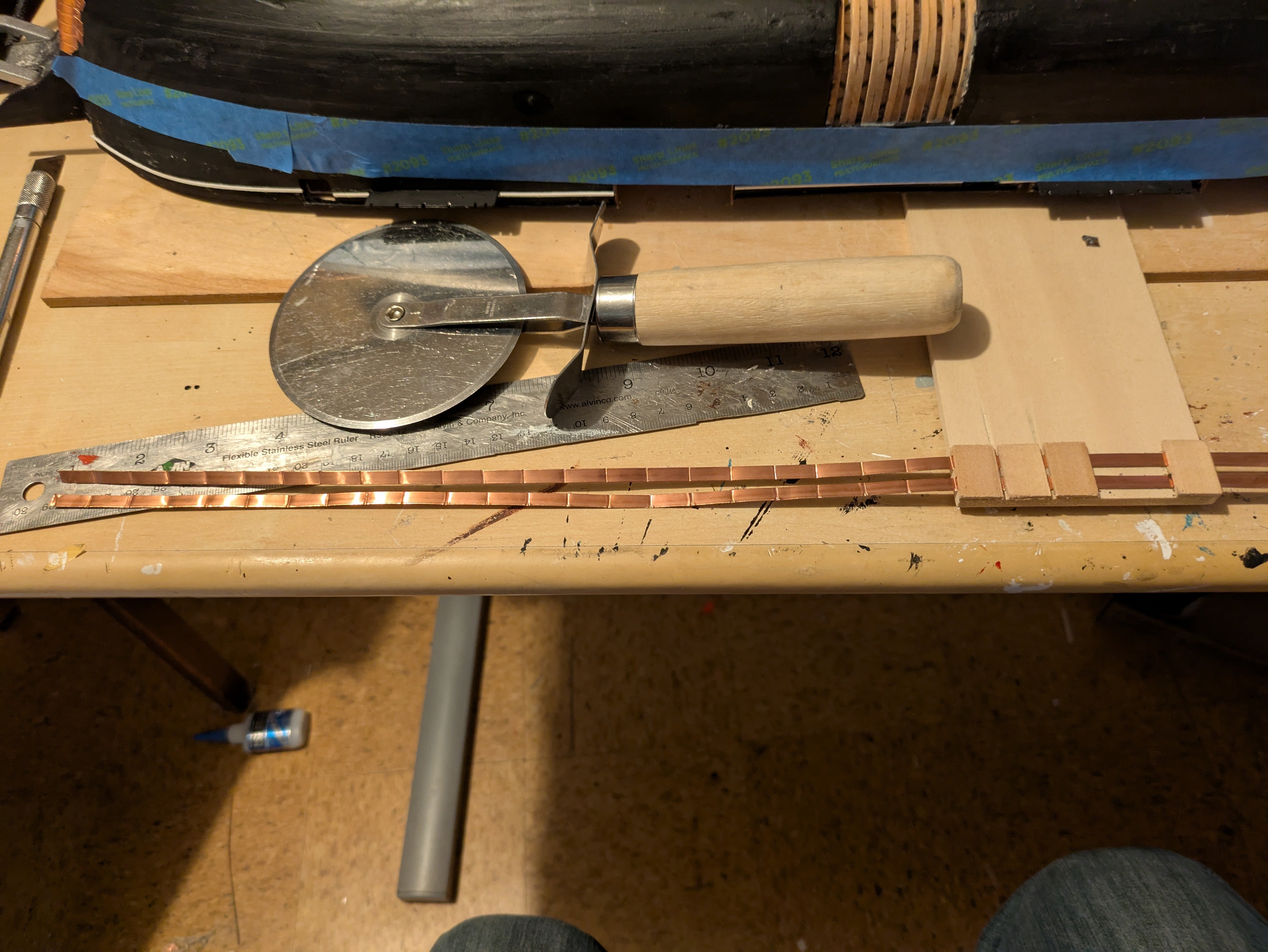
Next, here is my plate making apparatus, which I kept from the Fish. I run two sets of tape through the jig, use the pizza cutter to score along the two gaps on the left. Then I move the tapes so that the new scores are even with the left side of the jig and repeat. I tend to cut the strips into 6 plate sections, as anything larger can be difficult to work with.
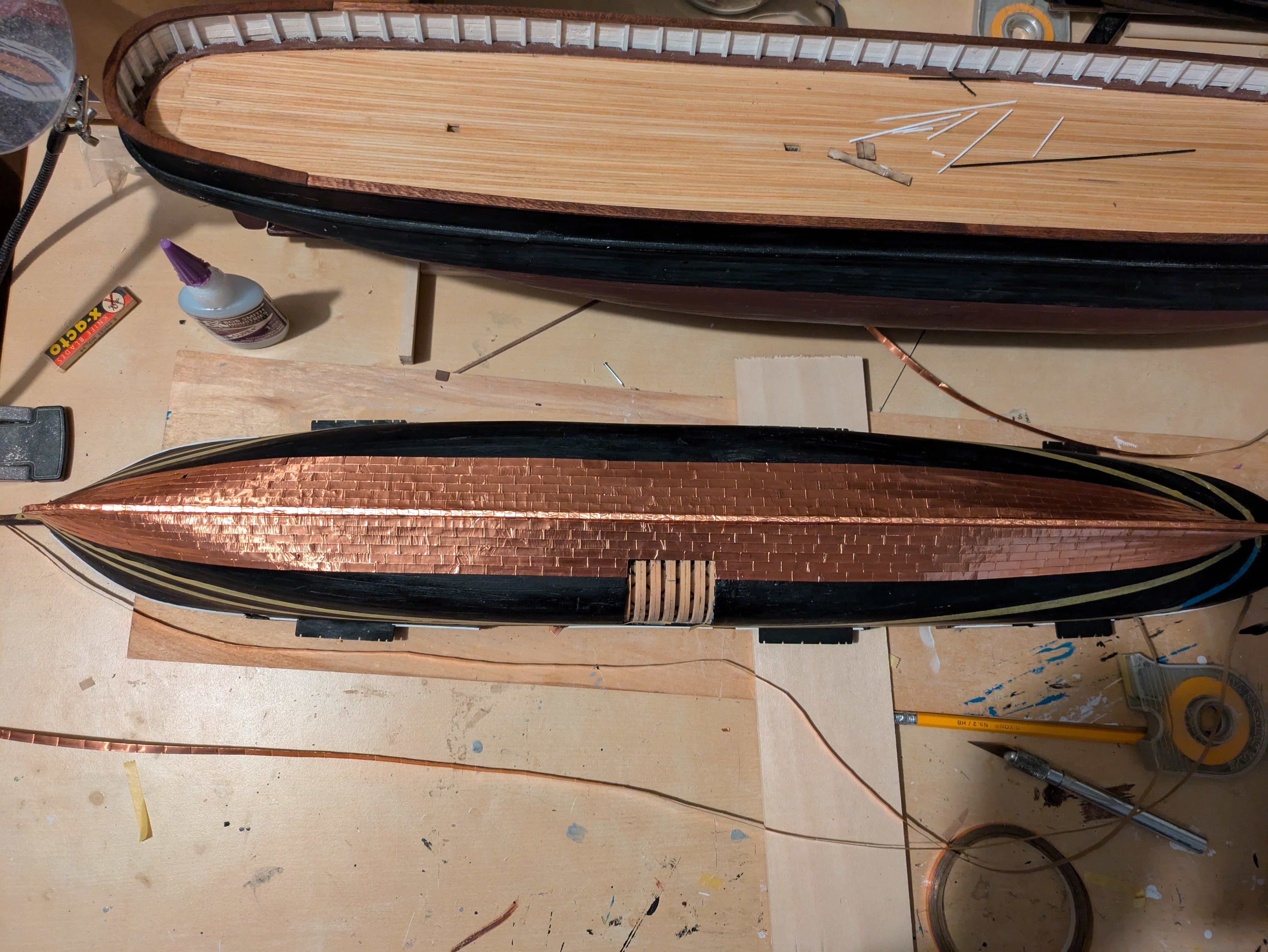
I use the adhesive from the tape to attach it to the hull, but don't bother with nail marks, which would be pretty much invisible at this scale. Instead I let the imperfections in the tape suggest the surface (including the nails). Here is the first few rows on the starboard side. First, overall, with the Disco in the background:
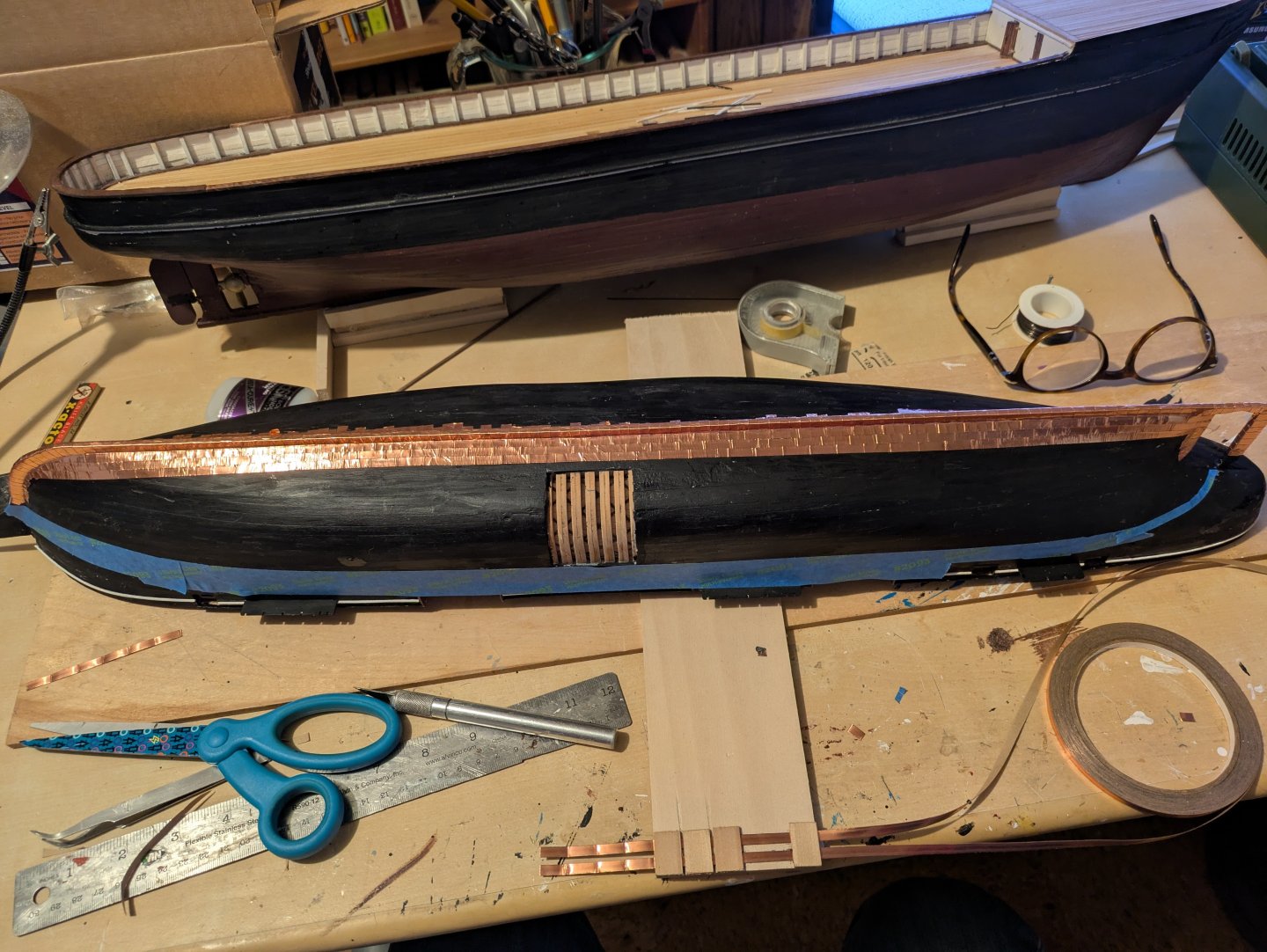
And two closer looks:
I wasn't sure how it was going to lay on the hull, but if you look at the bow you will see that the natural flow has a definite "upsweep". I expected as much, so will be laying down a bit of tape to mark a gore line. Basically, I'll run the tape up to the gore line and then restart the plates in a flatter arc. I'll point it out when I get there.
Thanks for looking in!
Regards,
George
- ScottRC, Keith Black, Canute and 6 others
-
9
-
6 hours ago, Jared said:
As I proceed through the rigging I am finding that some of the lines have begin to sag.
Hi Jared,
Glad you had a good time in Costa Rica. When you say that some of the lines are starting to sag, can you be a bit more specific? Are you concerned about the bit of slack in the tackles that are connecting the lifts with the deck or other lines, and if so, are we talking mostly standing or running? I found that I got a bit of slack in the tackles as well. Part of the problem (I think) is that the stress on the lines was bending the yards slightly up, which caused a bit of slack in the tackles. The crane on the model was made of brass, not iron and so bent more easily than on the real ship.
In a couple of cases, it got loose enough that I was able to do a wrap on one of the belaying pins, but I mostly just ignored it. No one else noticed, and real ships tend to not have running lines that are extremely taut when they don't have sails.
Regards,
George
-
It took more than a little bit of futzing around, but I tried @Javelin's idea of using wire, in this case, primarily 24 gauge annealed steel wire. The hardest part was actually making two sets of the wires. However, here it is, mounted on the ship:

It's not exactly the same as the real ship, but it is much better.
Regards,
George
- JacquesCousteau, Javelin, John Fox III and 4 others
-
6
-
 1
1
-
-
-
Thanks @iMustBeCrazy, @Lecrenb, and @Kevin-the-lubber, thank you for the suggestions!
I tried using card, but I found it tore too easily. Maybe my blades aren't sharp enough, but it didn't work. And unfortunately, I don't have access to a 3D printer or an entity that will make a brass copy alas...
However, I then returned to a thinner piece of polystyrene, and was able to make something that, I think works...? (the pieces are not glued on yet, they are just sitting there to see how they look).
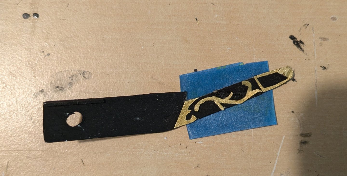
It's not perfect, it's probably as good as I'm going to get at this scale.
I also made the shield that is the figurehead on the ship.
It's not perfect, but it is probably as good as I'm going to get.
Anyway, I need to make a duplicate of the scrollwork for the port side, and then I can mount on the ship.
On a more amusing note. My wife and I teach math to apprentice shipwrights at the Alexandria Seaport Foundation, and when I was there, I noticed two gaffs being stored on the roof. At the jaws of one, there were standard wooden parrel beads. On the other, were these rather atypical ones:
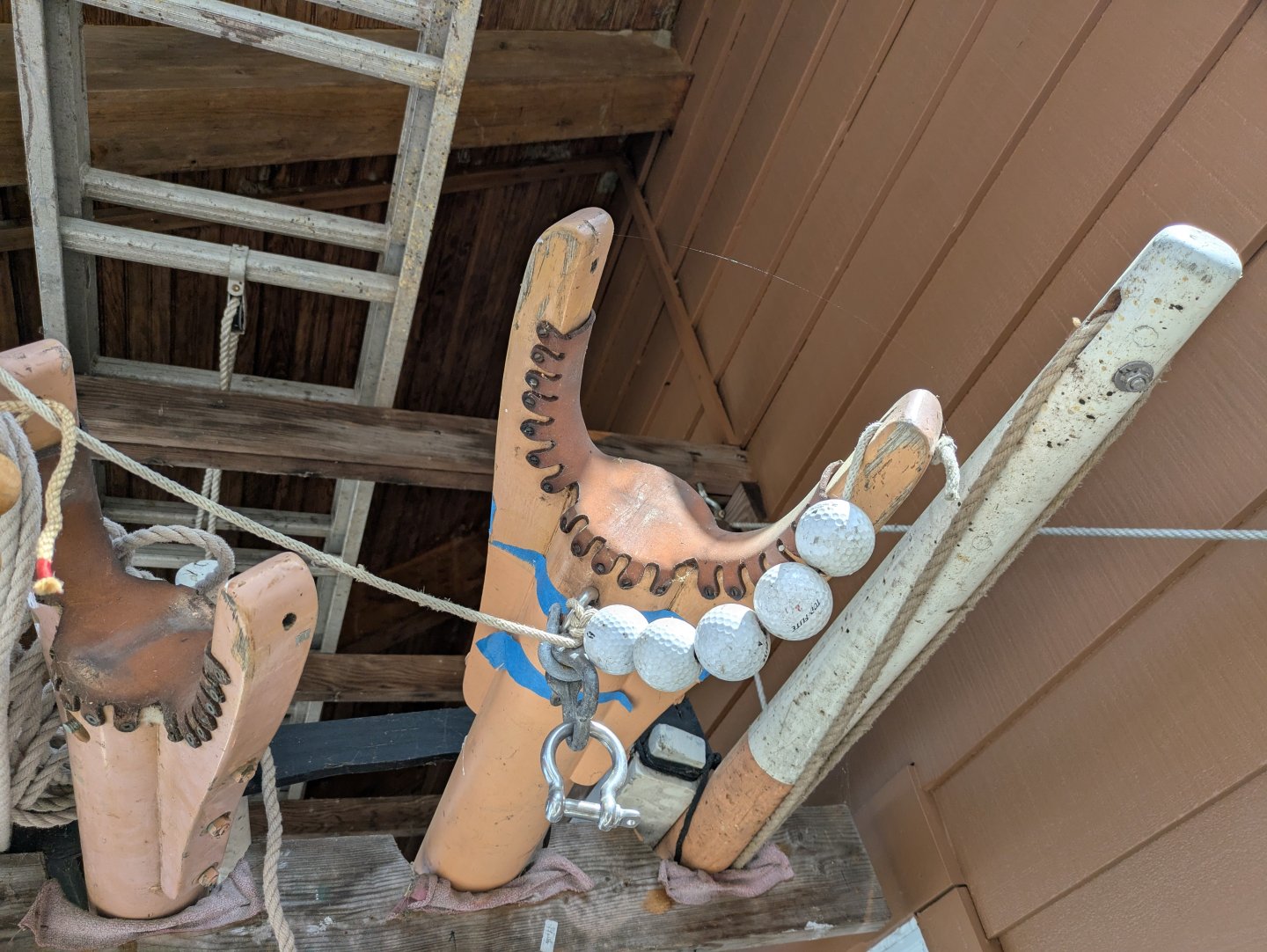
Waste not, want not, I suppose.
As always, thanks for looking in!
Regards,
George
- Canute, Valeriy V, Keith Black and 2 others
-
5
-
On 4/9/2025 at 7:43 PM, Rick310 said:
Those rails are nicely done George!
Great job of city the stern rail out of sheet!
Thanks Rick. Let's just say it took more than one try and leave it at that!
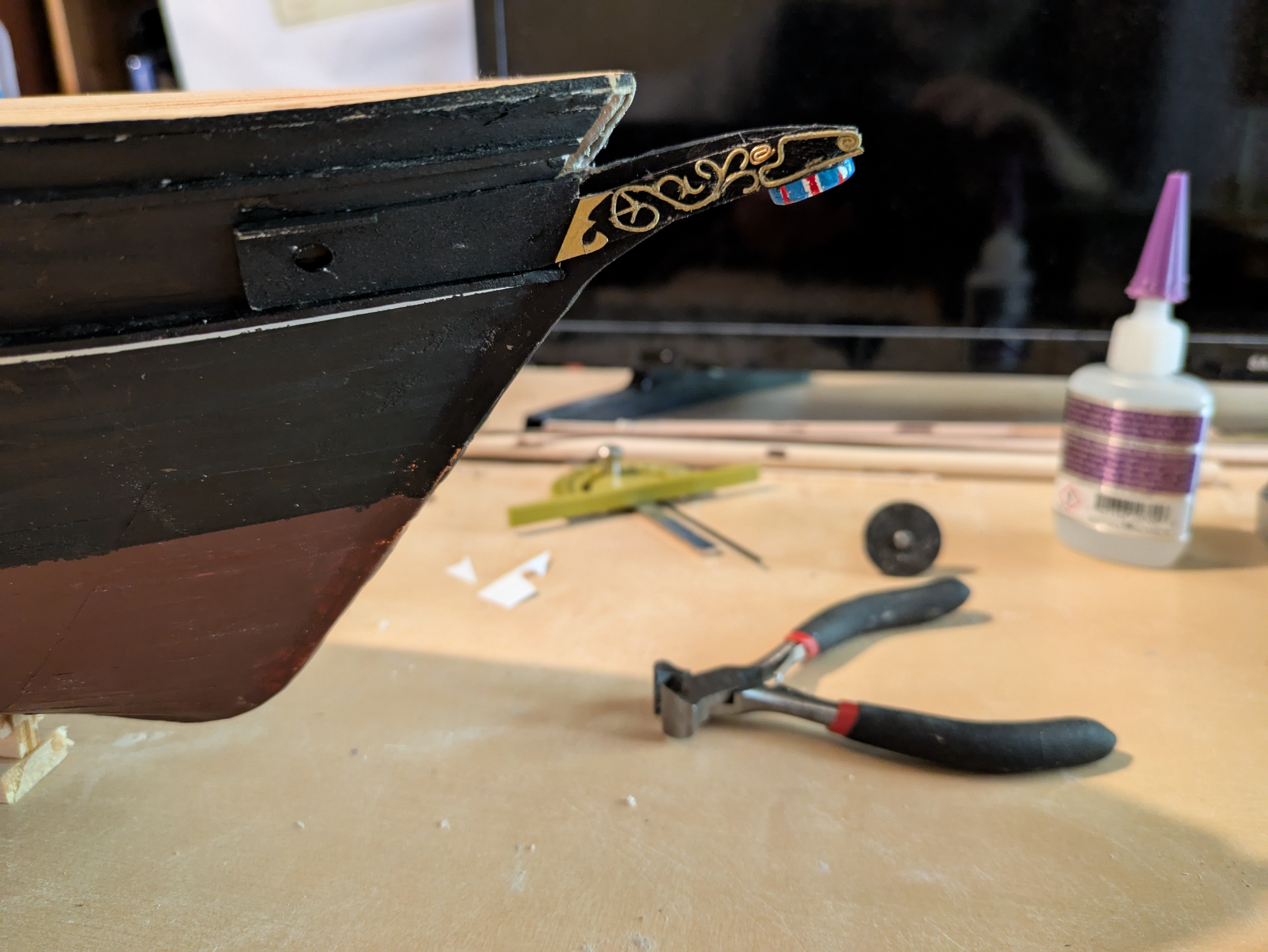
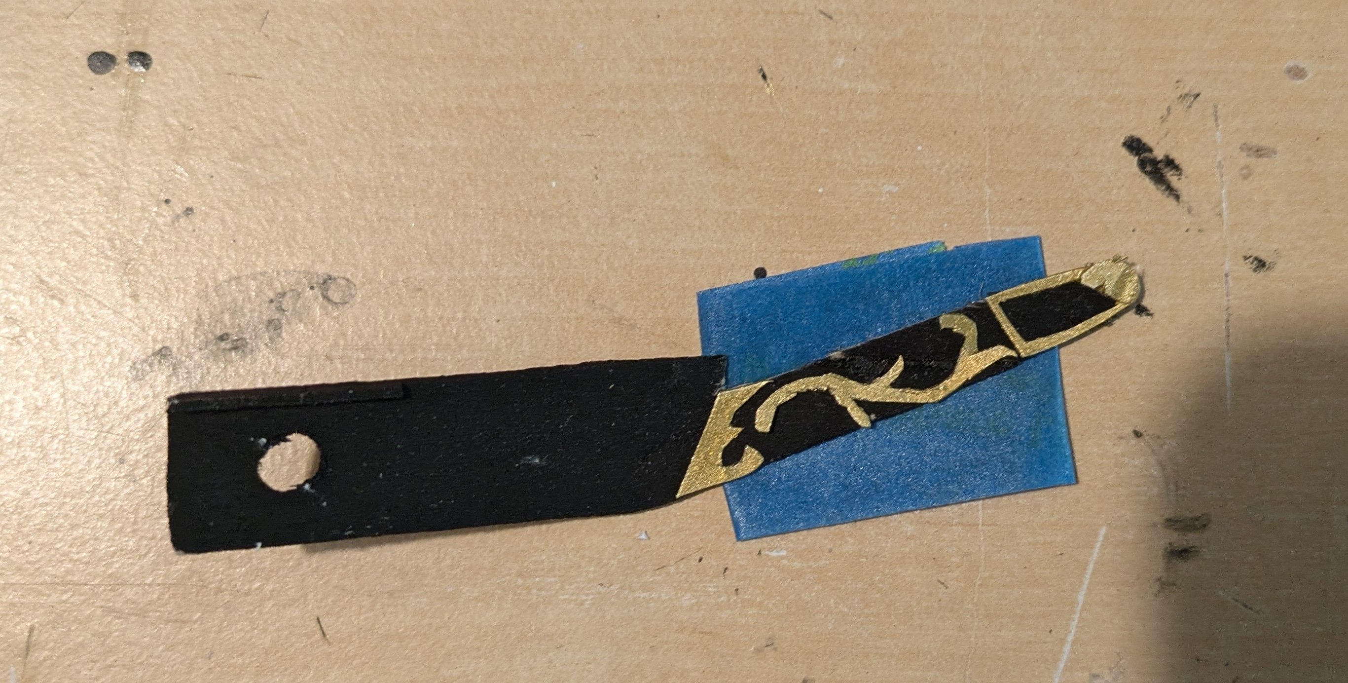
I've been working on the stem now. I had earlier cut and bent two pieces of wood that would represent the naval hoods (?) which have the hawse holes and the scrollwork on the stem. Drilling the hawse holes was easy, I've been working on the scrollwork which is much harder. Here is the ship stuck in the ice in 1901, you can see the scrollwork (probably gilded since it is a different color than the white stripe).

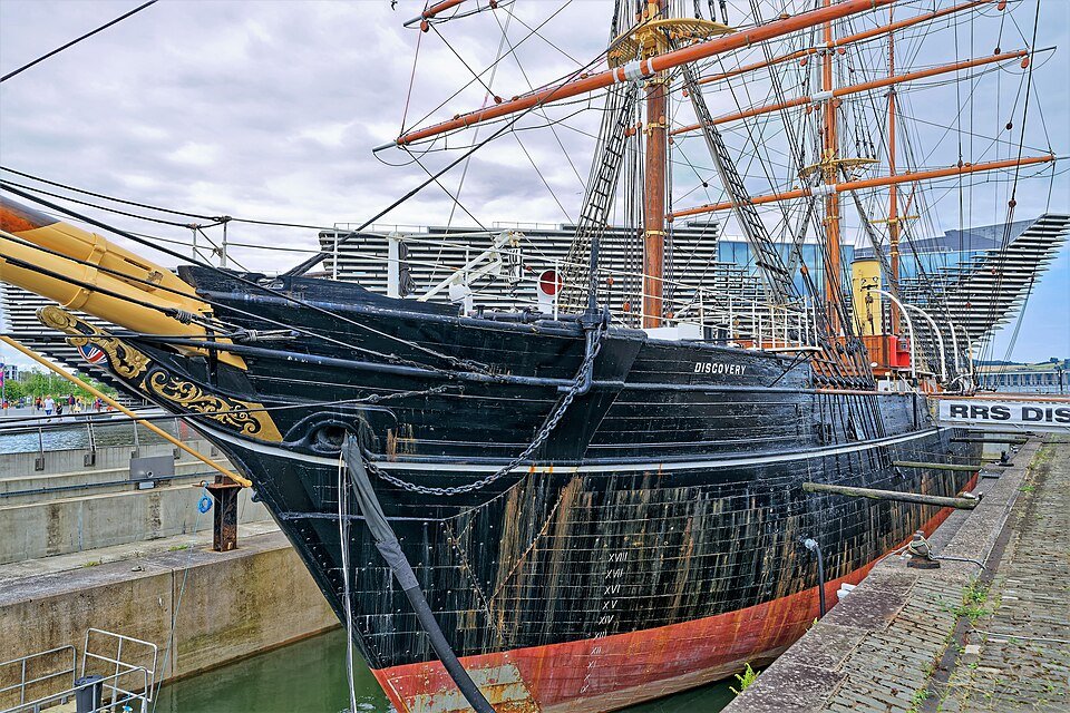
Here is the ship in 2010 with (nominally) the original bow:
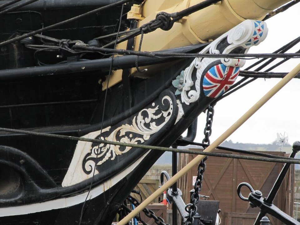
Here is the ship today with a replacement (nominally identical) bow (licensed CC-BY at https://commons.wikimedia.org/wiki/File:1901_wurde_die_RRS_Discovery_in_Dundee_vom_Stapel_gelassen._02.jpg:
The scrollwork is, to say the least, complex. My original thought was to simplify somewhat, cut it out from 1/32" thick bass, sand the edges, paint them, and mount onto the naval hoods (or whatever the correct terminology is). However, I have found that I can't cut even a simplified version out of 1/32" bass, the things just break (repeatedly). I've tried cutting things out from polystyrene sheet. This seems more promising, but getting something that doesn't look like it was done by a child has proven complicated.
Any thoughts on this? I've looked at some of the carving tutorials on the site, but they seem more focused on taking pre-cut items and carving them to be more three dimensional. Are there other materials I should be thinking about? I know that I'm going to have to simplify it given the scale, but so far my best attempts have looked simplistic at best.
Anyway, appreciate any insights anyone might have.
Regards,
George
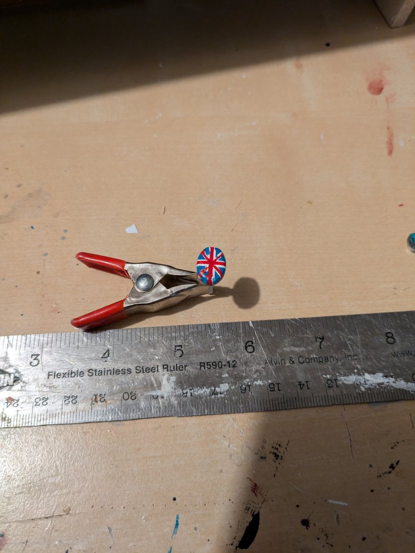
PS - The Union Jack is going to be made separately.
- Keith Black and Canute
-
2
-
Jared,
She's really looking fantastic!
Glad you took the time you needed, and are ready to proceed apace.
Regards,
George
-
Hello! I am also George from Washington, DC (well, Rockville a bit north of you). Welcome to MSW!
George
-
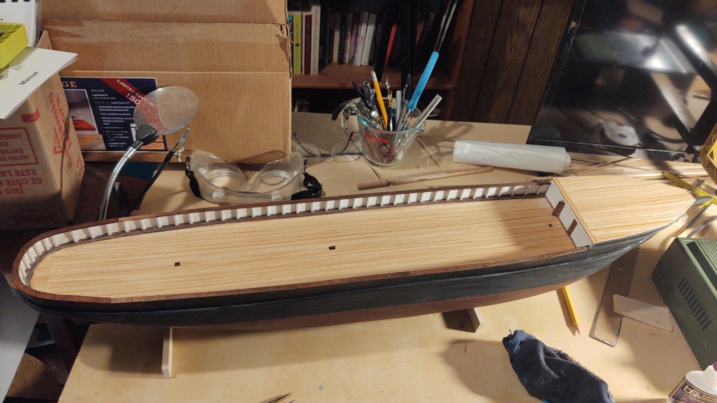
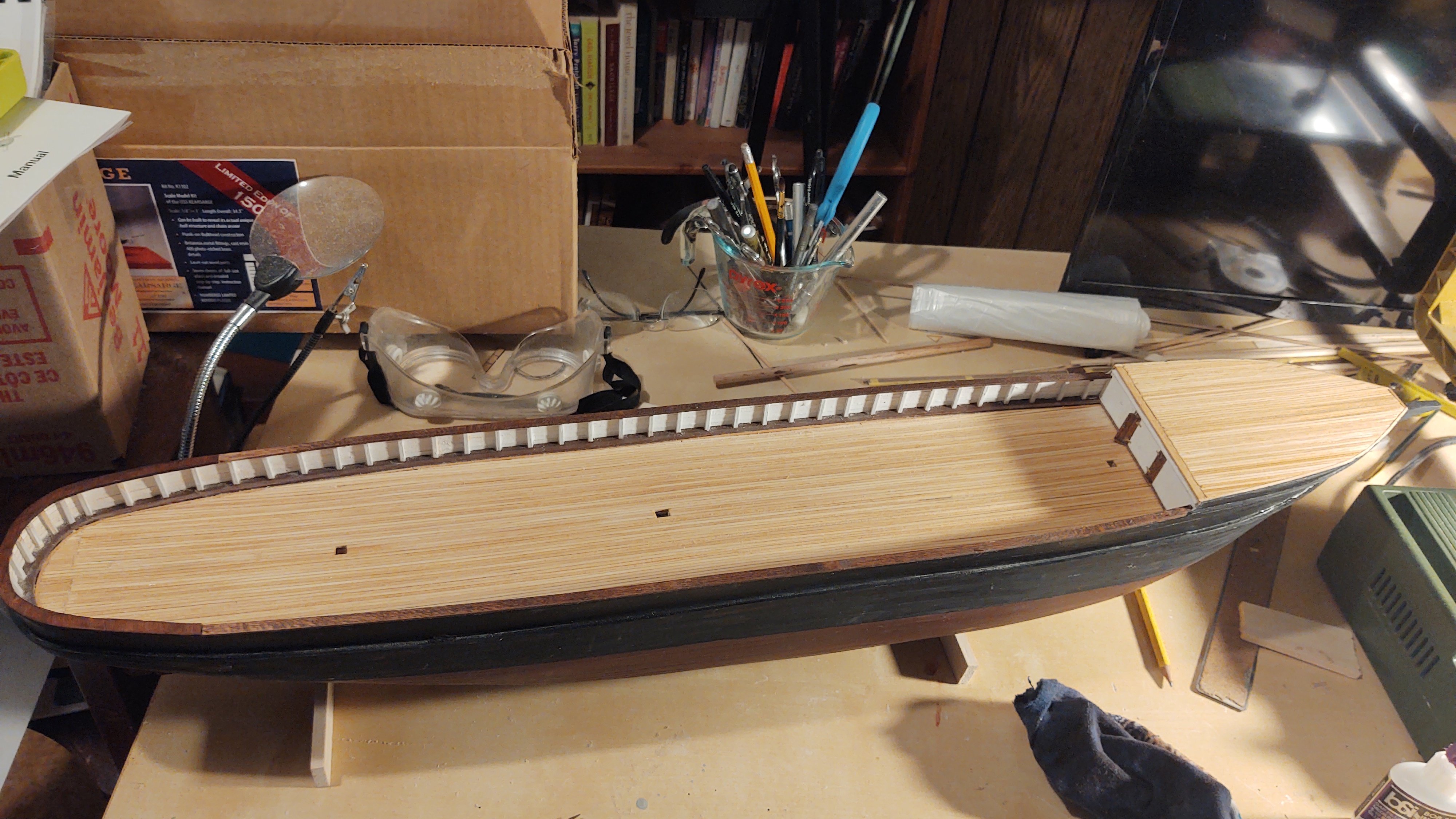
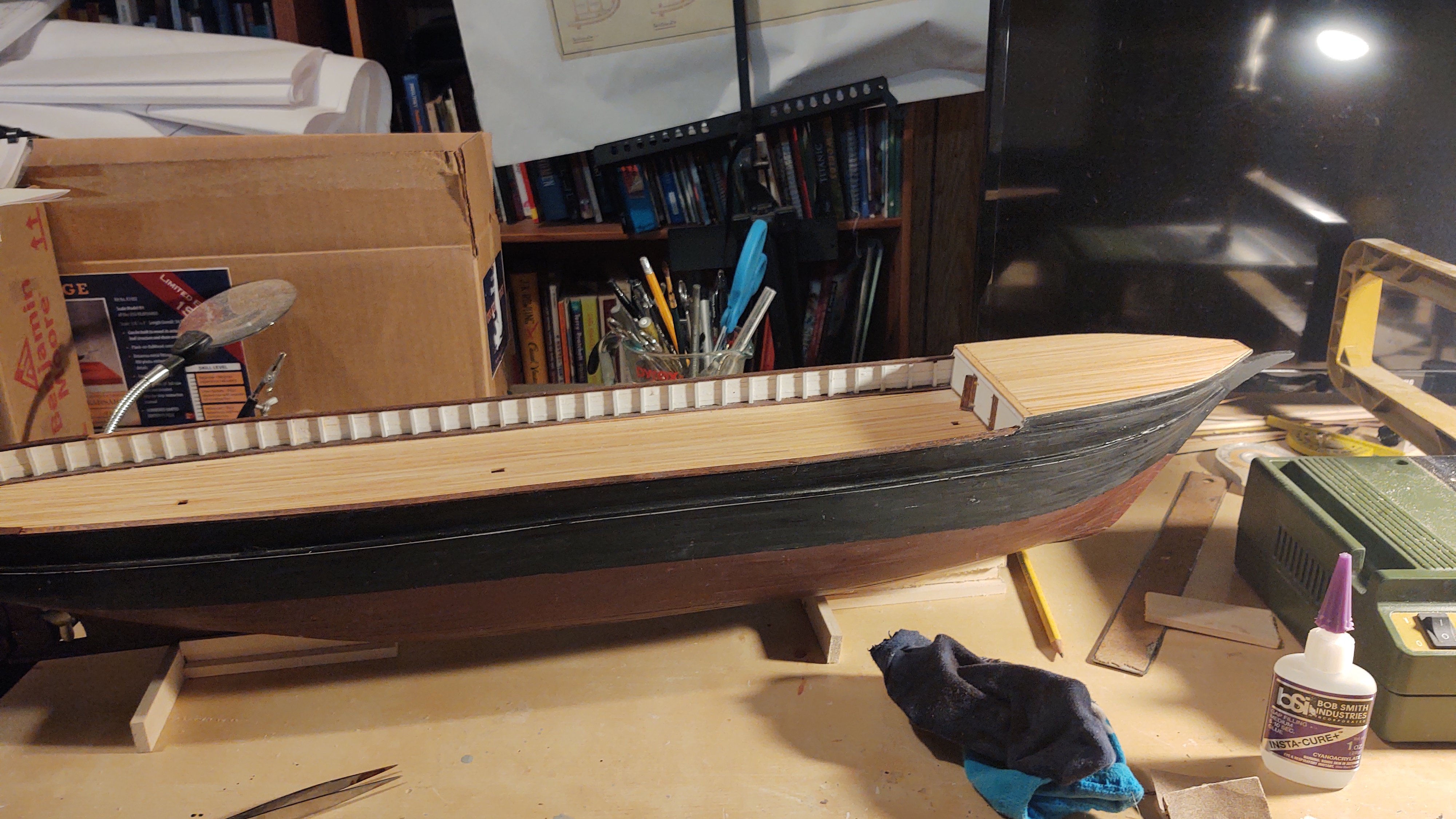
Quick update. I've cut, stained and installed the cap rails. Most of the rail is made from 1/16 thick bass I cut to 6 mm wide. The stern is cut to match the stern from a piece of 1/16 bass sheet and fitted in place before staining and permanently gluing.


Regards,
George
- Keith Black, Valeriy V, Javelin and 5 others
-
8
-
1 hour ago, Rick310 said:
George, I think the prop could be raised to eliminate drag when sailing.
The prop/hub came out great!!
Rick,
That makes a lot of sense. The ship was not a great sailer, and if it was pinwheeling a prop with a steam engine attached, I imagine it would be a lot worse.
Regards,
George
- Keith Black, Ian_Grant and Canute
-
3
-
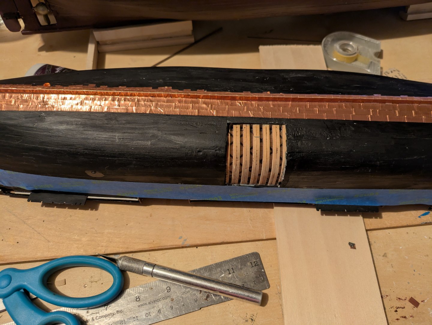
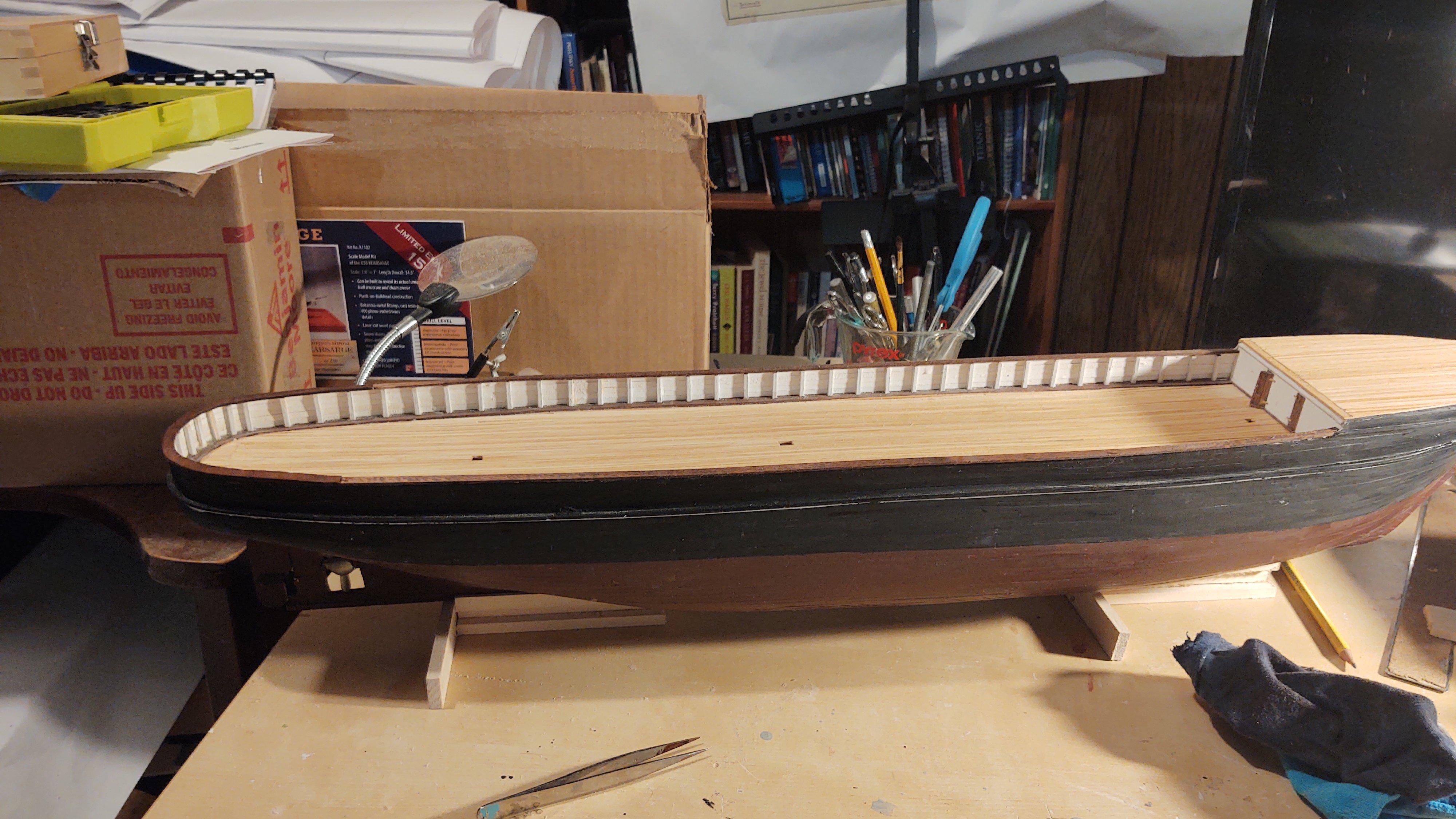
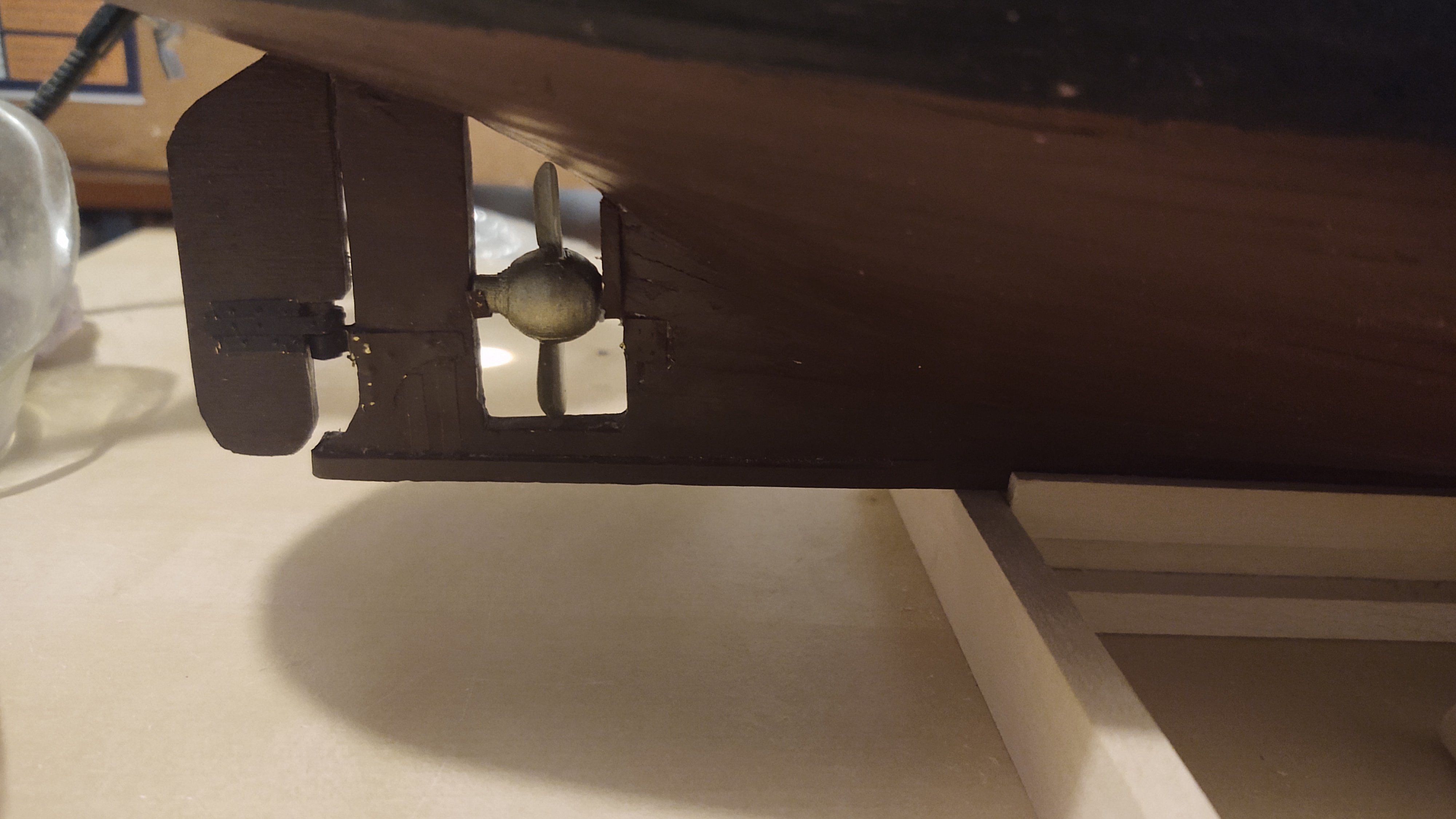
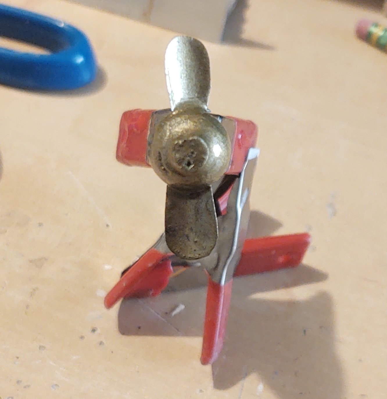
One last propeller update. Mounted on the ship. On the stern side it is mounted into a small cradle made from brass strip and painted. On the forward side, there is a channel that runs from the shaft to the hull above (you can see it in the ship photo a couple of entries back). That is there to enable to prop to be pulled out and replaced from the deck in the event of damage. I've added that in using painted brass. So, here it is:
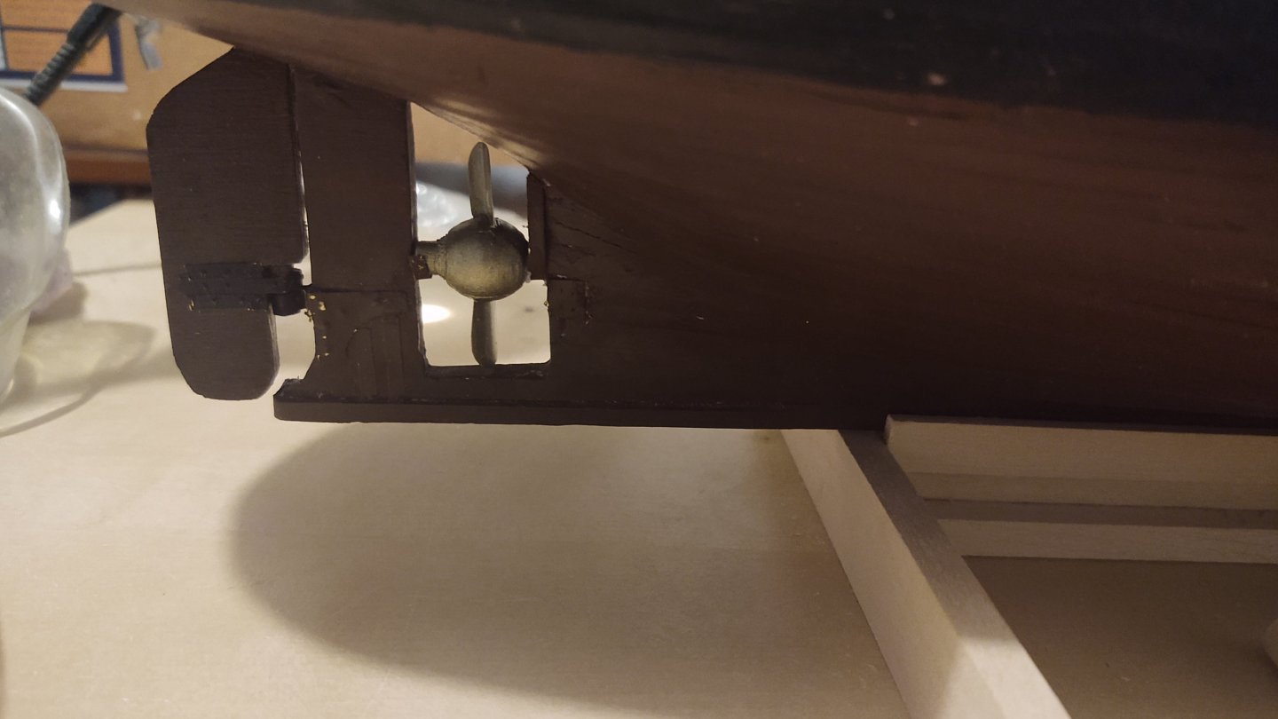
One thing I didn't model is the actual octagonal hole that goes through the hull that allows the access from the deck (and a similar rectangular access point for the rudder). It's mostly hidden, it isn't a regular octagon, and it just went into the too hard pile. I will be modeling the access port on the deck (it's a piece of deck furniture). I mentioned that it isn't a regular octagon, but, sort of a flattened octagon. Seven sides are the same length, but one is not - I presume related to the width of the hull at the exit point, but still very weird.
Anyways, have a great weekend everyone!
Regards,
George
-
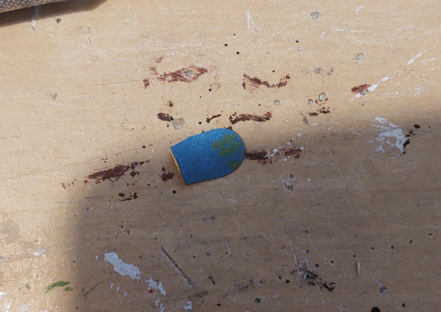
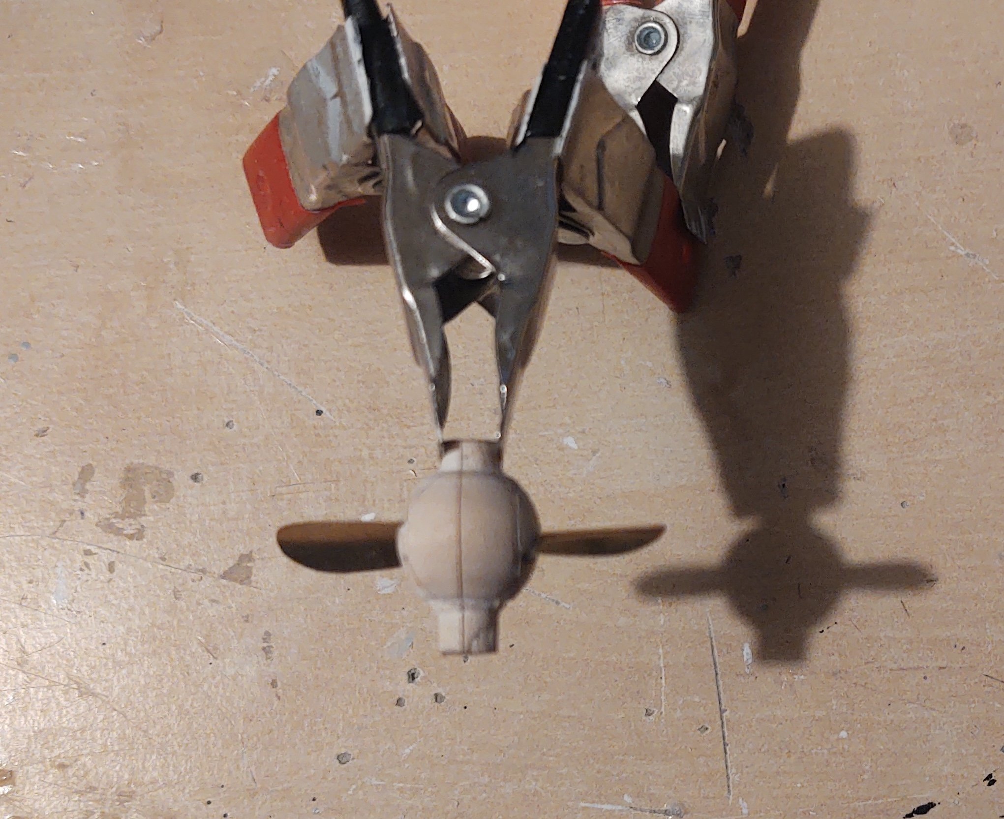
Okay - the prop is done. Here is the basic sequence. I cut out the blades from brass sheet, using a bit of painters tape to draw the outlines:
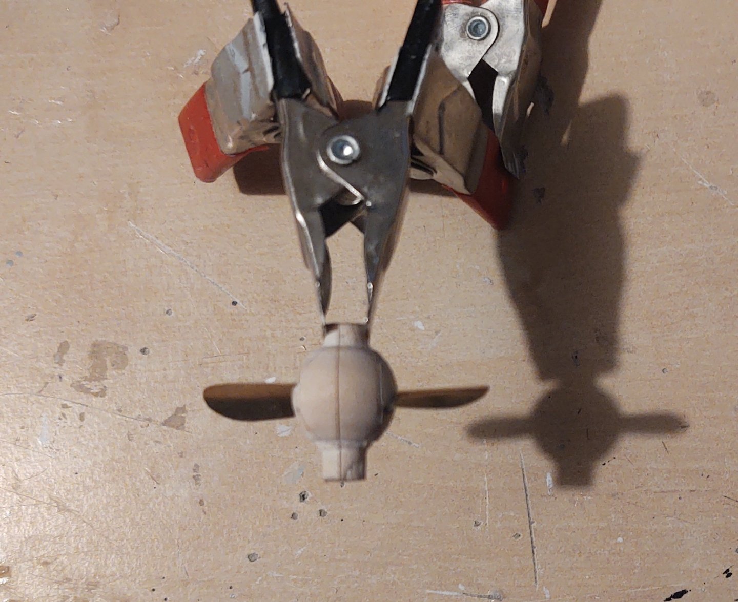
I used a knife handle to curve the blades, and then fit them into a curved cut I made in the hub:

Here it is before painting:

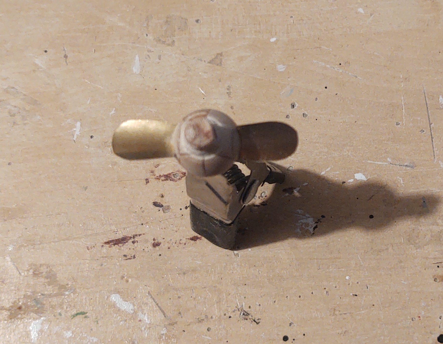
This was where I made, an, ah, mistake. I had a bottle of Tamiya "bronze" paint. Here is what it looked like after a coat of paint (yikes):
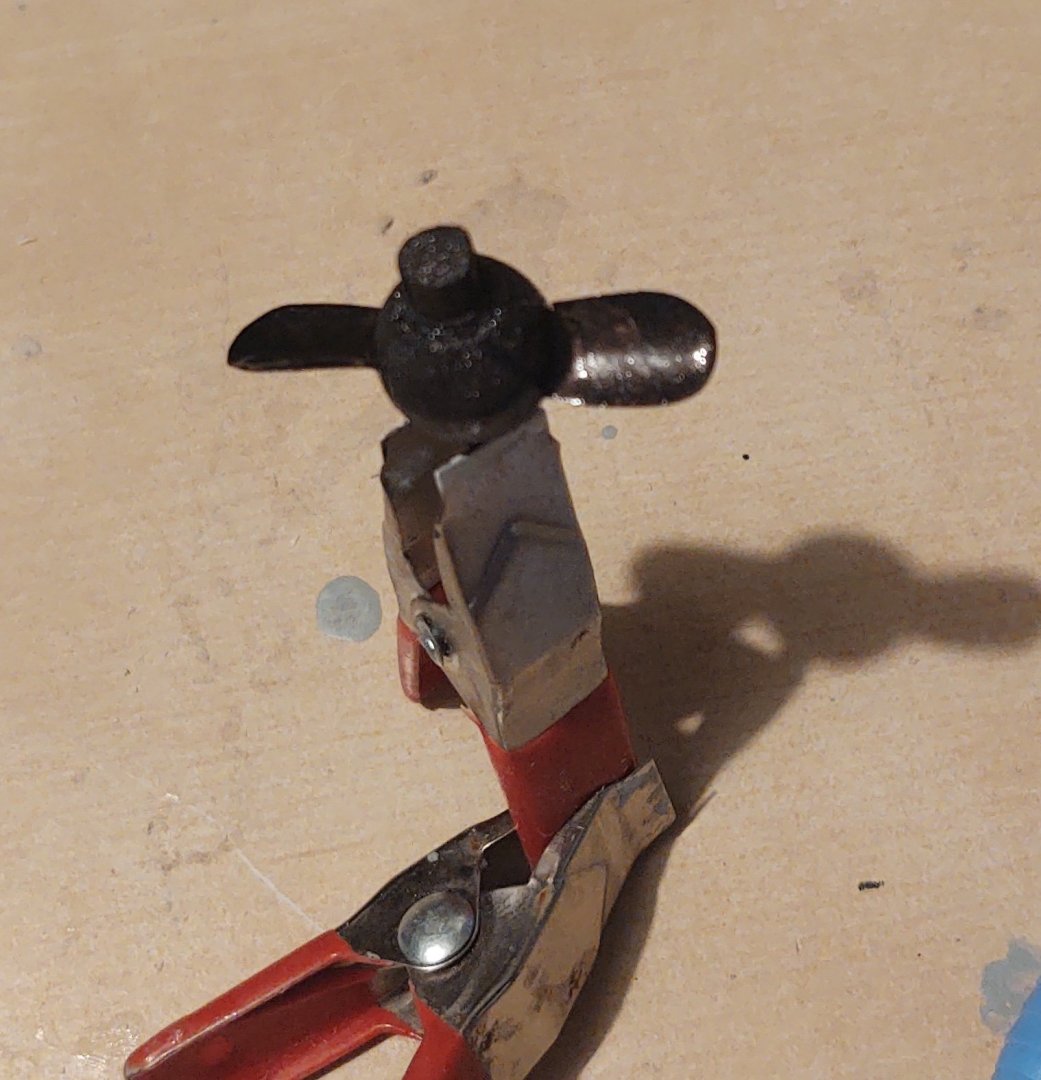
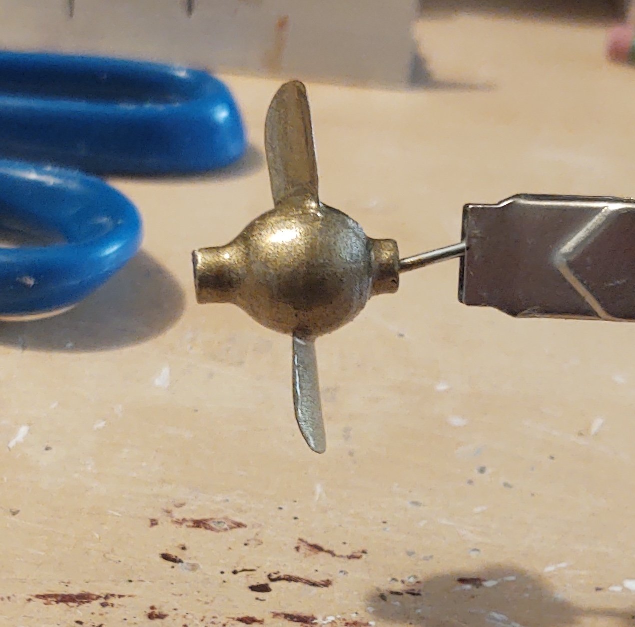
So, suddenly doing additional research I should have already done (and frankly when I opened the bottle, I should have cottoned to), I learn that the bronze used on most propellers is in fact an alloy of copper, tin, and zinc, which makes it both a bronze (copper + tin) and a brass (copper + zinc). Either way, I took some Tamiya gold paint and mixed it with the bronze until I got a shade that made more sense. A quick sand with 320 grit sandpaper to even out the first coat, and we get the following:

which I think you will all agree is much nicer.
Regards,
George
-
22 hours ago, Keith Black said:
Jacques, rule of thumb, the higher up the smaller the block. The blocks you have will work out great because all blocks were not the same size. Bigger on the bottom and smaller at the top.
Concur. Plus, as the boat ages and things break, they get repaired with what is available - if it's a different size or looks a little different, well, no one is going to replace all of the block for aesthetics.
She's looking great!
George
-
Quick question. So, I gather most propellers were made of bronze (even to this day). What would the shaft have been made of in 1901? Iron? Steel? Bronze? Trying to decide how to paint the shaft. I mean, Given that this is meant to be removable, would it make the most sense for it to be a single bronze casting?
Any help appreciated.
Thanks,
George
- Keith Black and Canute
-
2
-
I tend to use annealed wire as well - same reasons - it's black and easy to work with.
GAK
- Keith Black and Jared
-
2
-
@Rick310, appreciate the comment!
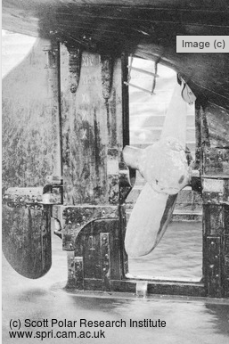
Now, the prop. Here it is on the ship.

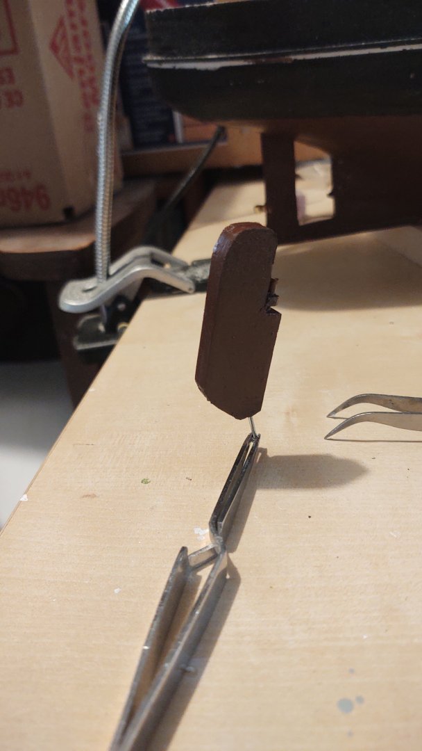
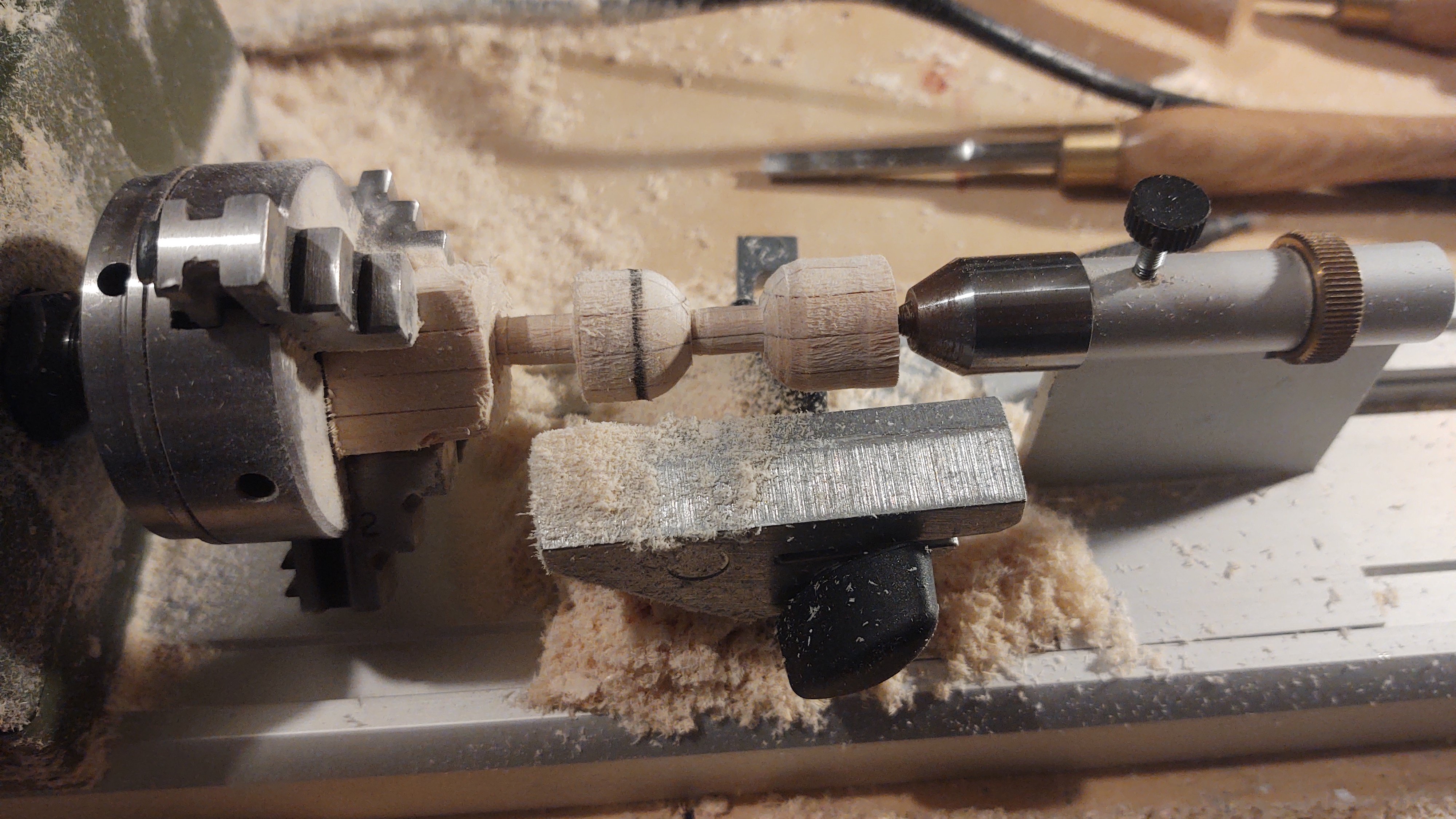
My initial question was how to make the ball that holds the blades and the shaft as one piece, two pieces (a ball with a hole drilled through it for the shaft), or three (a ball with two dowels glued on as shaft segments. My initial thought was to try to fabricate it as one piece and see where we go from there. This is one place where the plans have let me down, as they don't show much detail on the prop - so I've been forced to work from photographs like the above. The "ball" at my scale should probably be in the 12-15 mm diameter range with about 4 mm worth of shaft visible. I didn't have a big enough dowel or single piece of wood handy, so I glued up 12 segments of 1/4" by 3/16" (4x3) into a 3/4 by 3/4 inch wide billet, cut it in two, and mounted it in my little lathe.
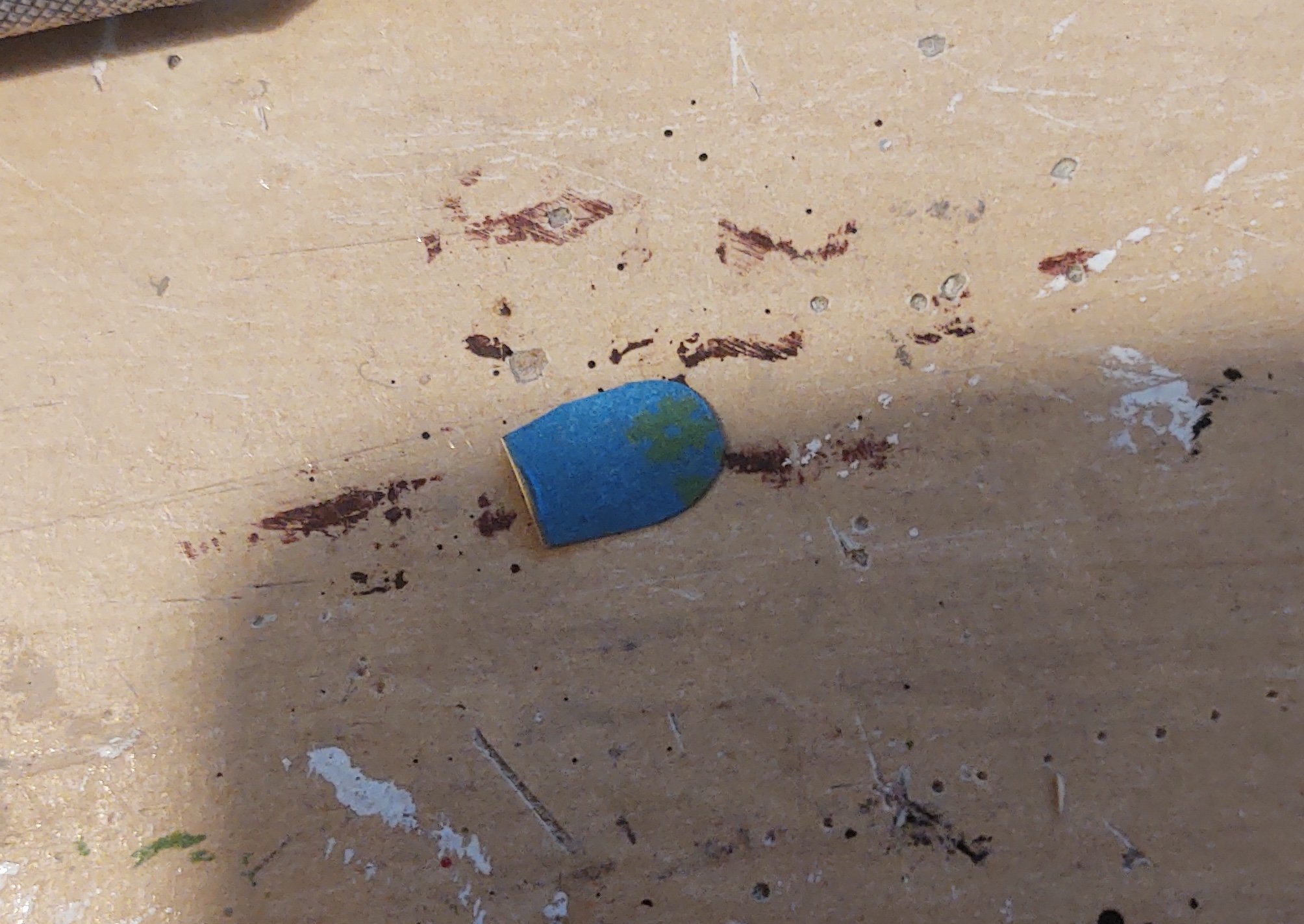
So, step 1 was to round out the square billet (this photo is from attempt 1, all of the others from attempt 2). I've also started defining the boundaries of the shaft vs. the ball.
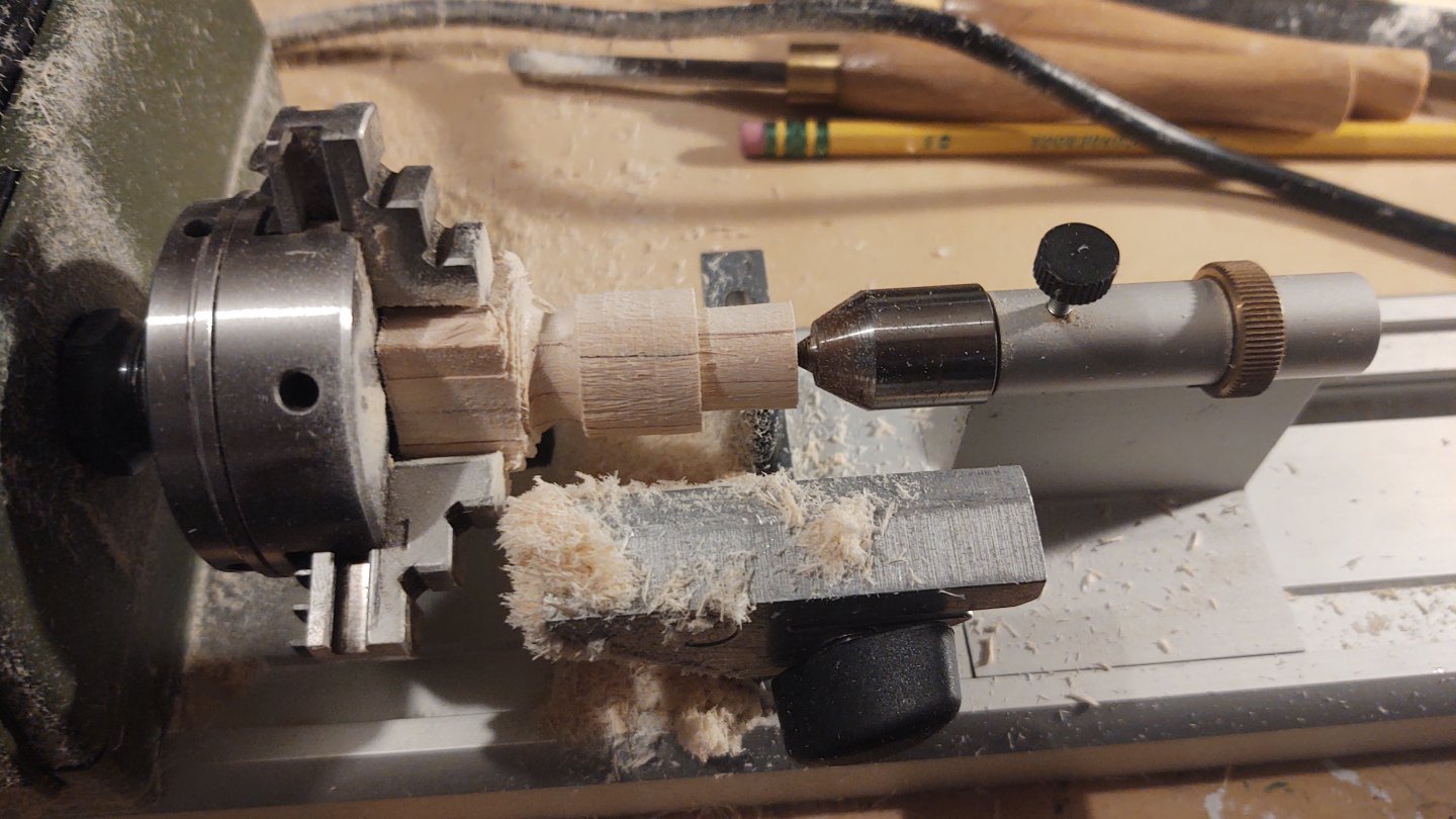
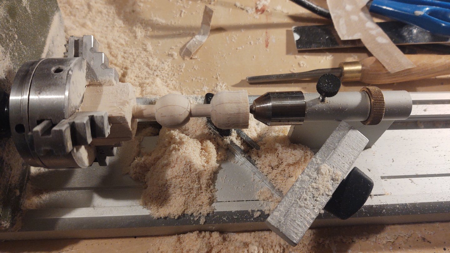
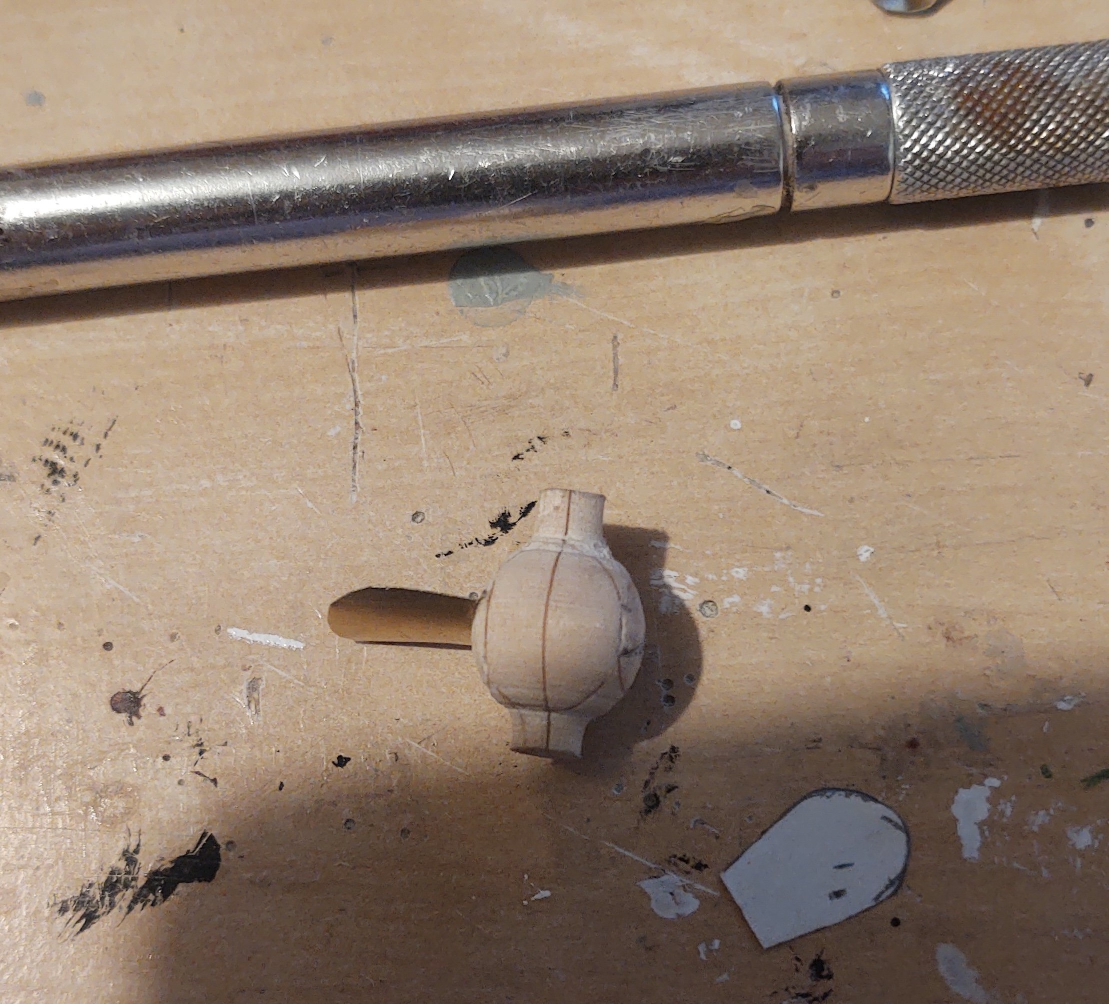
Here it is further along. I've defined the ball and shaft pretty definitively, marked the center of the ball, and started cutting away ball shape on the right hand side.

And here it is after trimming further, and sanding with some 150 grit.
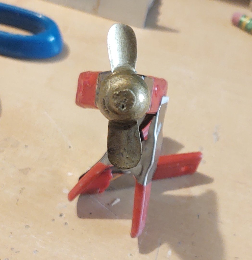
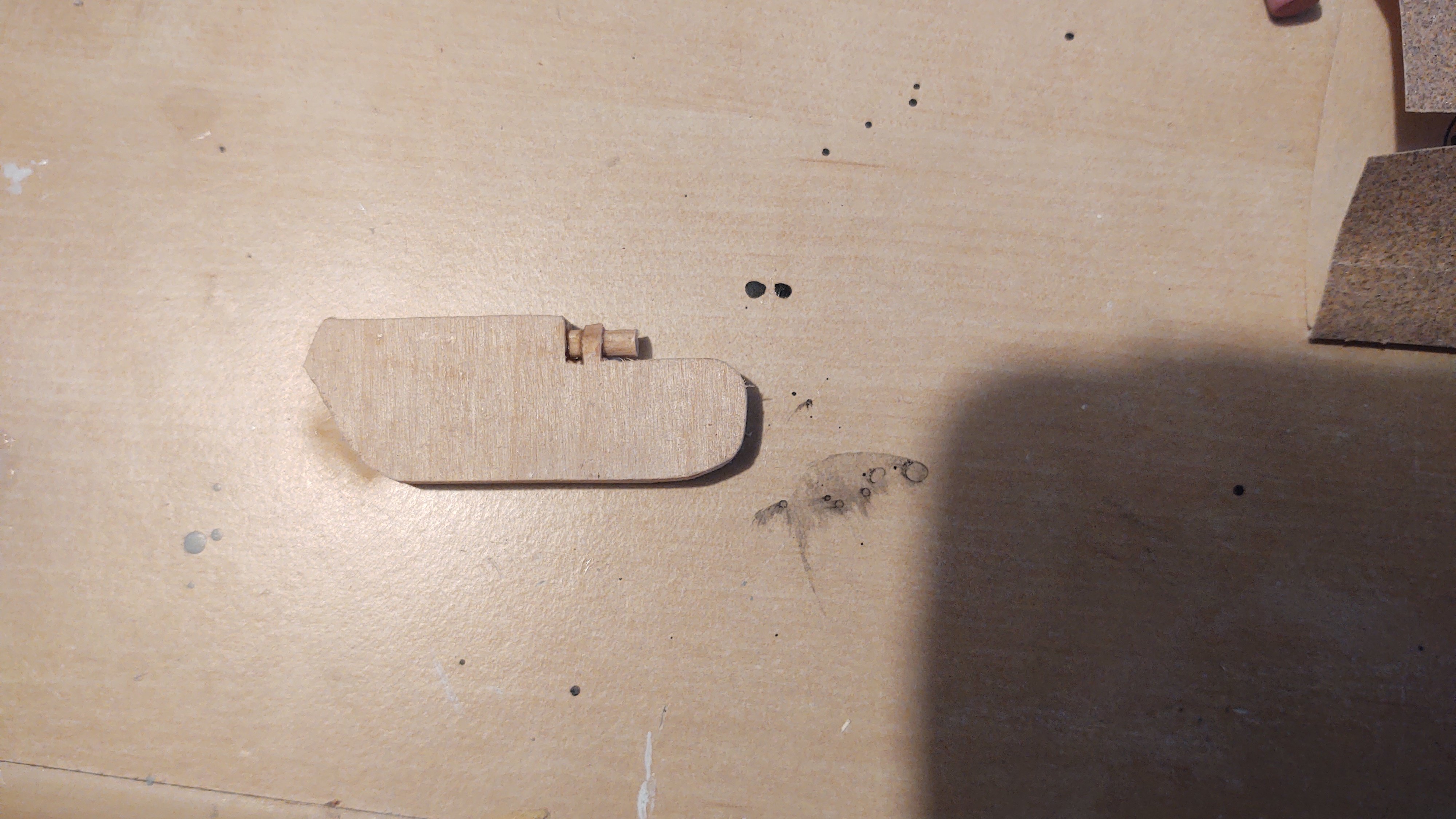
I've cut it out and I need to see if it is visually the right size (it may be a bit too large), in which case, I'll put the piece back in and sand it down until it appears correct. Once that is done, fill any gaps and cut out where the blades will mount into the ball. I'm not going to try to model the "bolted on" blades at this scale, but I think it's going to look just fine.
As always, thanks for looking in and for the likes.
Regards,
George
-
Today's update is the rudder. This is the rudder as it was when the Discovery was in dry dock in Australia (a section from https://www.spri.cam.ac.uk/picturelibrary/catalogue/article/p83.6.2.3.2/:
The rudder is one piece, and quite wide (as wide as the sternpost), and doesn't seem to have much in the way of beveled edges. Here is the blank:

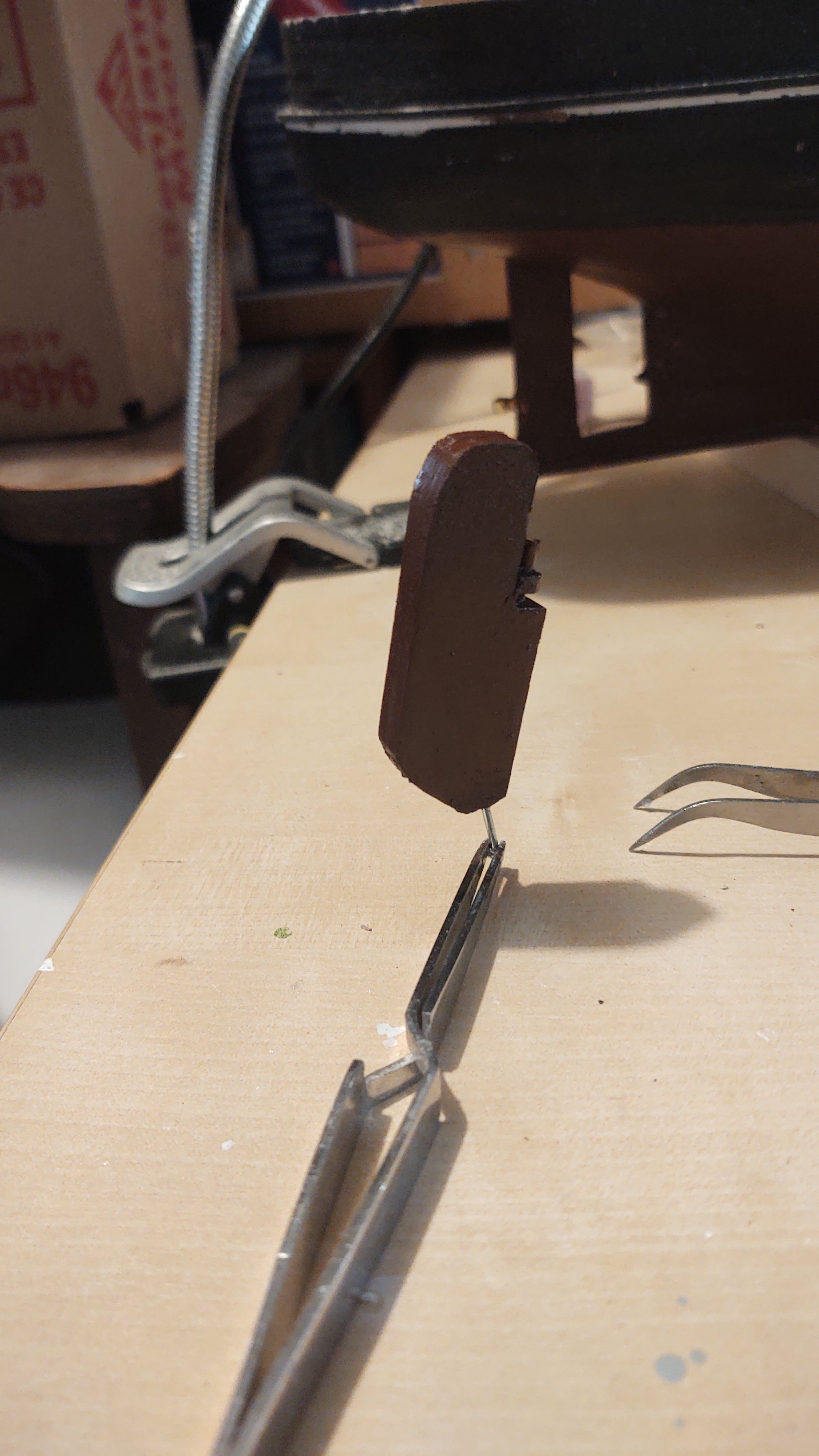
Rather than build a separate iron work for the pintle, I made the "iron" pintle holder out of wood, and glued slightly smaller dowel pieces above and below, and then shaped the wood that represents the iron holder semi-circular. The rudder was then painted hull red, as all of it is below the waterline.
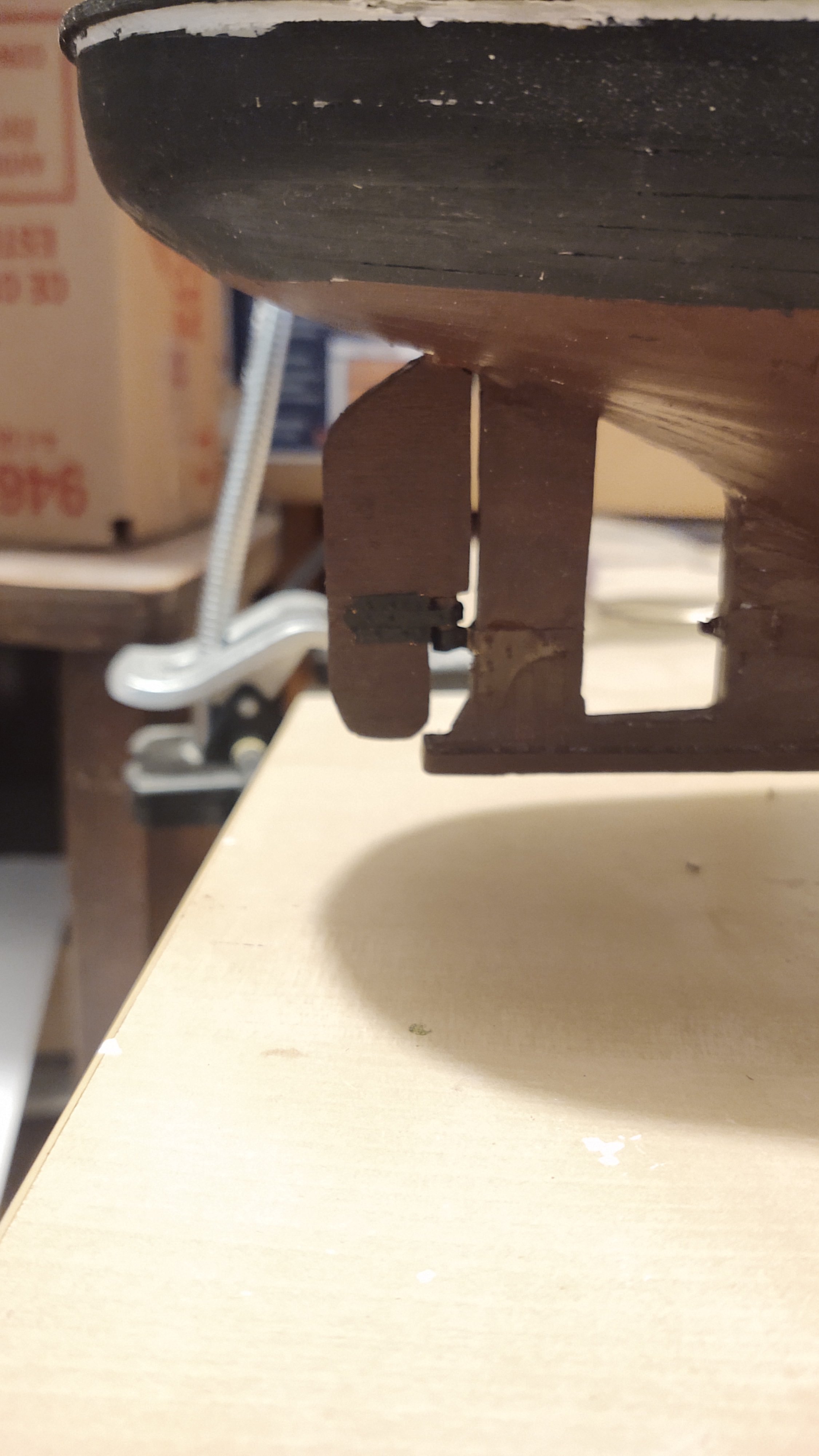
The rest of the "iron work" was made from 1/4 inch copper tape that I cut to 1/8". I made the "bolt heads" with a nail and a ball peen hammer, and then painted the copper black, and added it to the rudder. The pintle was fitted into the previously made gudgeon, and the top of the rudder glued into place.

As always, thanks for looking in and the likes.
Regards,
George
-
On 3/3/2025 at 3:21 PM, Jared said:
Sorry you had to spend so many hours interviewing and all for nought. Their loss!
Thanks Jared. Looks like it's going to work out in a good way, particularly given my father and in-laws advanced age.
Back to the actual ship (which had been sitting on the side for a bit while I did some work on the Kearsarge. The forecastle on Discovery is closed off, so I needed to build up a bulkhead with two doors. Here is a photo of the real ship (from the Scott Polar Institute website):
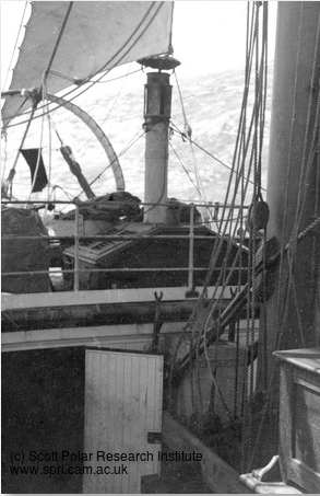
It's hard to see (although not on the original) that the bulkhead is made up of vertical sections of wood that appear to be about 3 feet thick, and there are two doors. The insides of the doors are white, but it looks like the outside is darker (and that is the way the ship is today - although that is of questionable value for here. I want the bulkhead on the model to be 1/16 inch thick and still show the vertical planking.
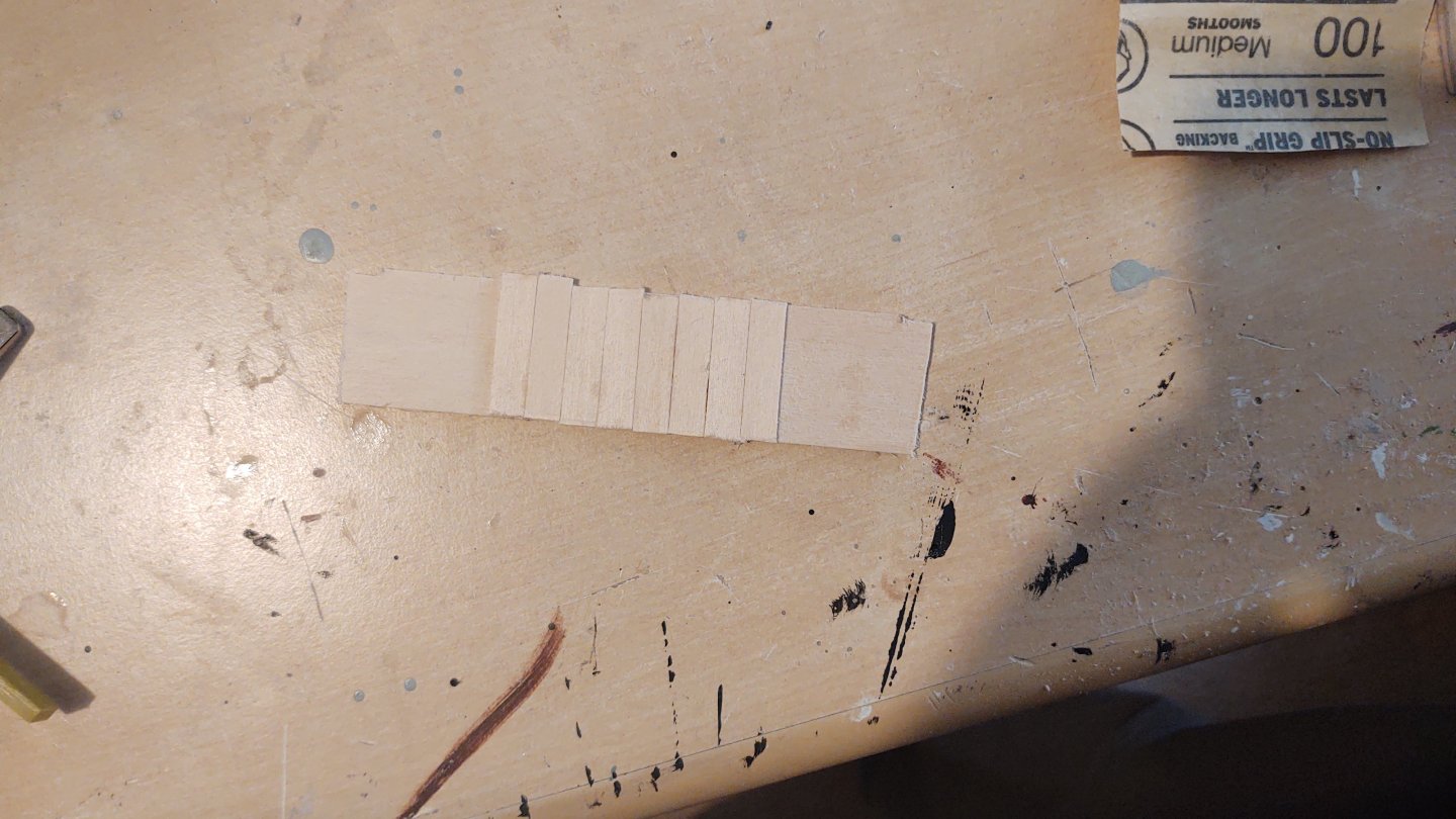
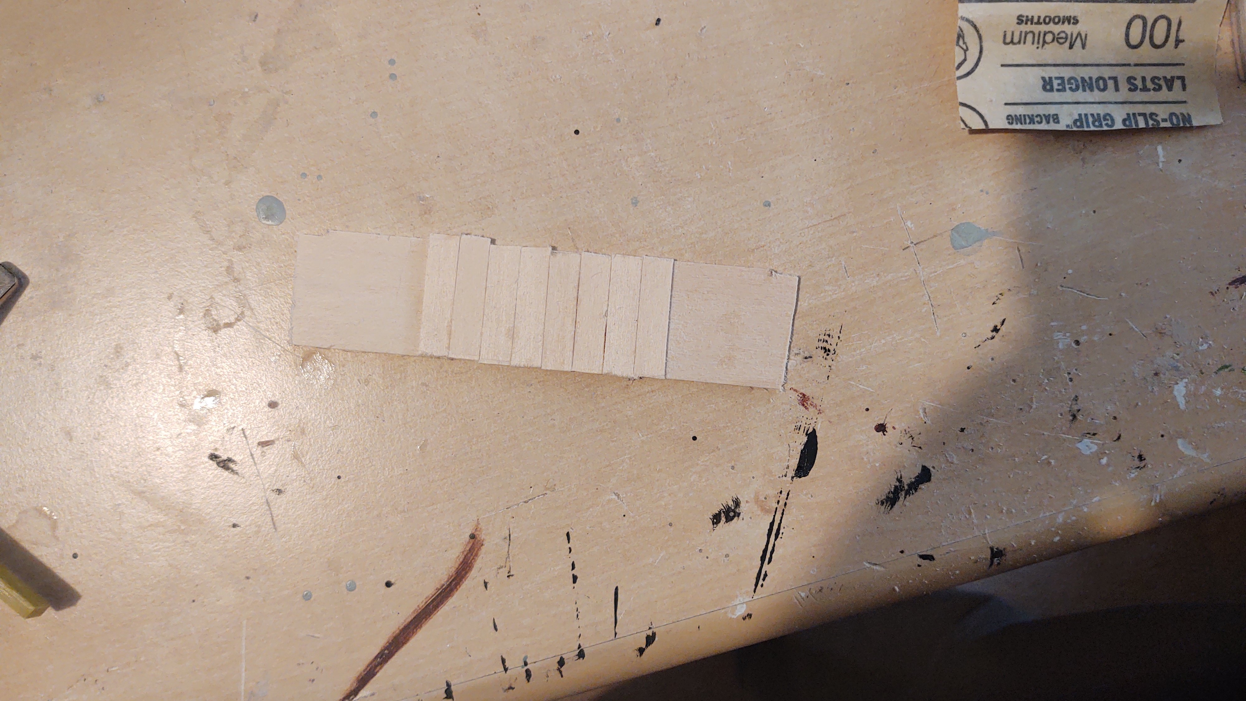
First thing, was a took a piece of 1/32" thick stock and fitted it to the opening to the forecastle. Then I took my 1/32" stock and made 6 mm wide strips, which I cut and glued onto the piece I had cut out and fitted to the opening. Here it is partially complete:
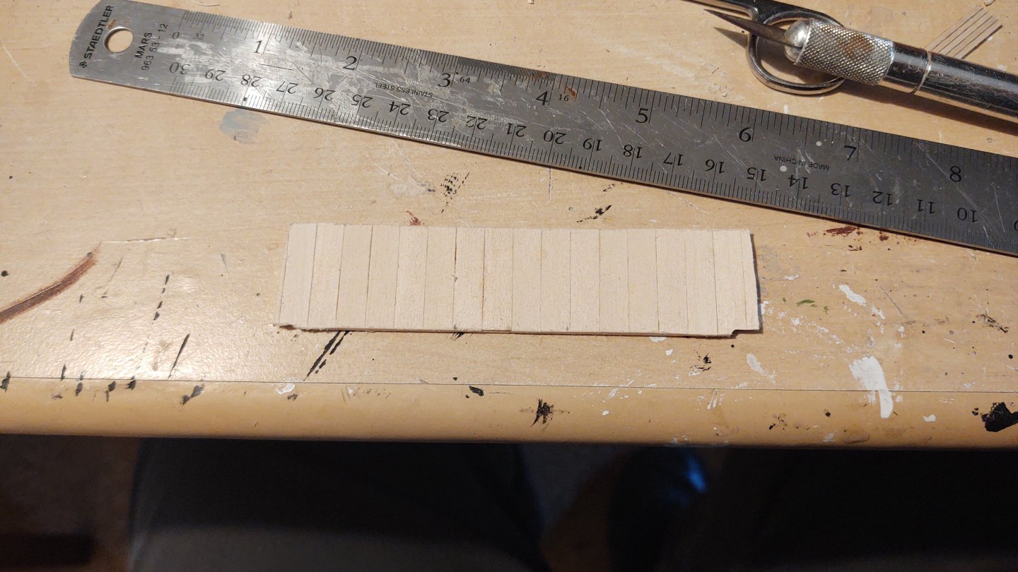
And here it is, complete, partially sanded.
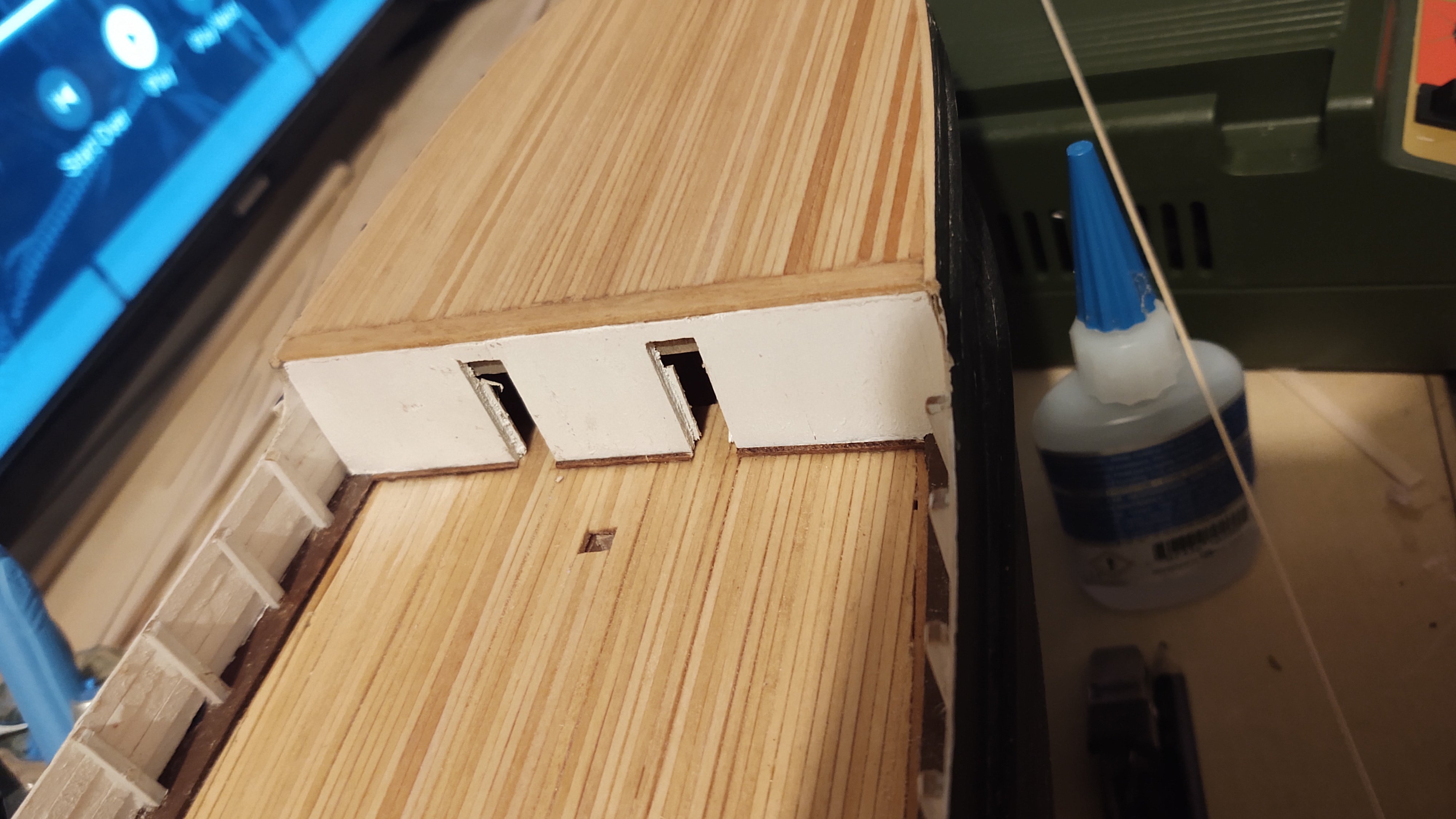
After sanding it to fit, I cut out the openings for the two doors, put some scrap behind the openings for the doors to fit into, and painted it white, as per the photograph. Then, install into the opening:

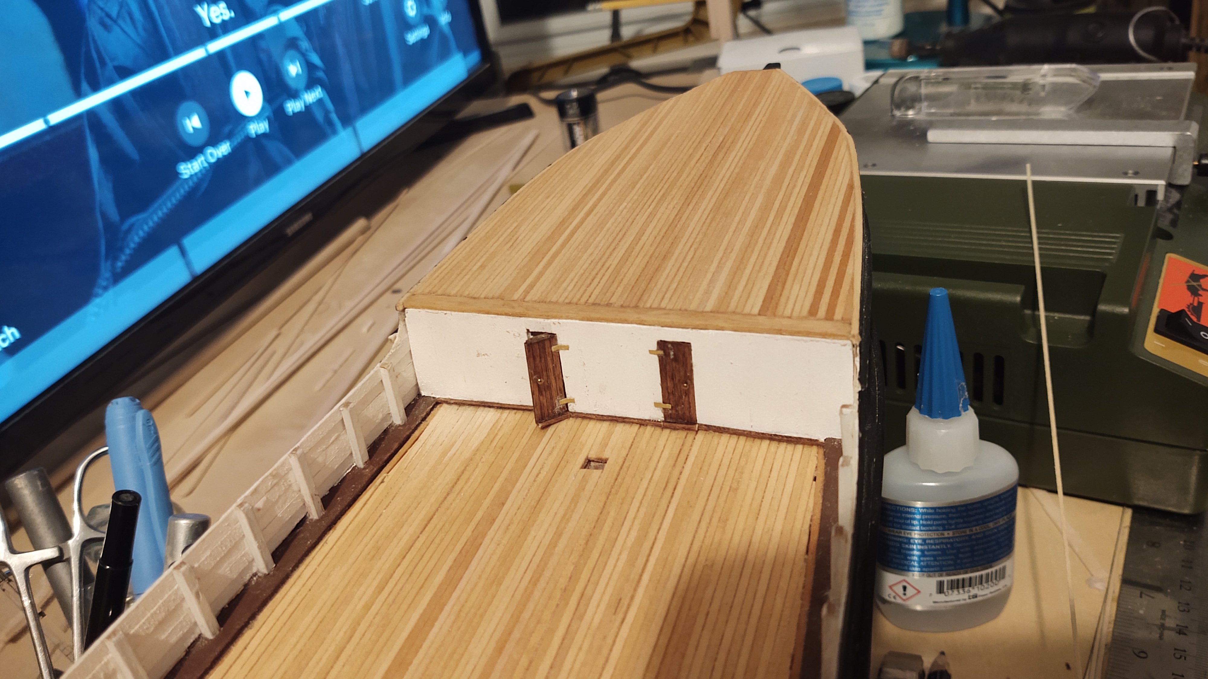
The base of the bulkhead is 1/32" square basswood stained red oak. I made the doors out of some scrap, scribed decking I had from another project, backed with 1/32" basswood. The doors were stained with red oak, so that the scribing still comes through, while providing some contrast. I glued a bit of stained 1/32" square bass on the base of the door as in on the bulkhead, and used leftover belaying pins for the doorknobs. The hinges were made out of brass. I didn't paint the hinges because they were within about 30 feet of the magnetic observatory, and would have fallen under the "no ferrous metal" rule, like the fore chainplates, which were made out of brass. One door was closed and the other left ajar:

Finally, I mounted a bit of 1/32" square stock painted white across the top of the bulkhead, a similar decorative touch is visible in the photograph.
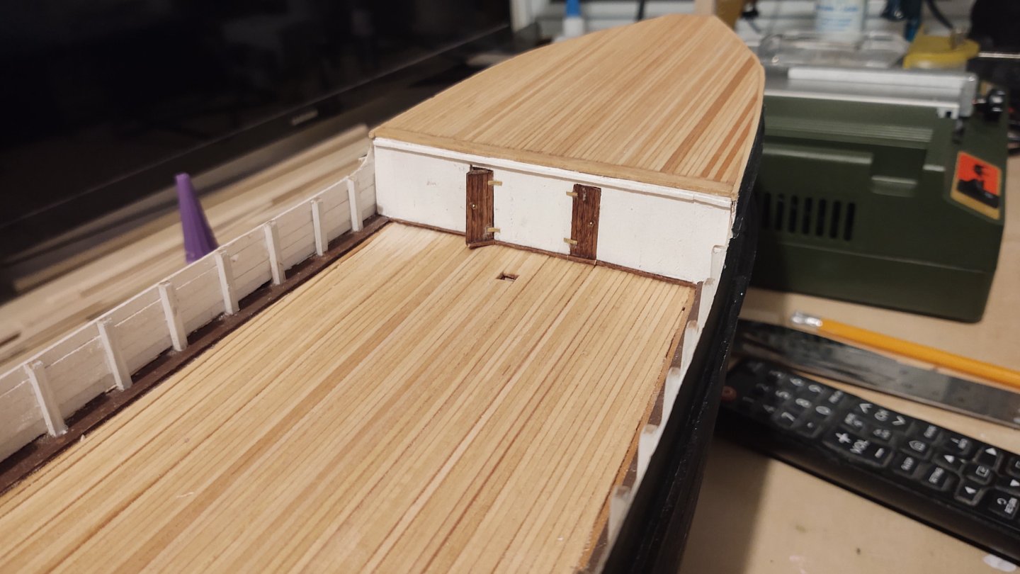
All in all a lot of work, considering that the vertical lines are practically invisible. BTW, one of the reasons that the port door is open is so I can get to the anchor points for the lower forestays which are in the forecastle. So, the door should swing open more, but since there is nothing to see in there, it will likely stay only ajar once the stays are in place.
As always, thanks for looking in, and the likes! I hope everyone had a wonderful St. Patrick's Day if you indulge.
Regards,
George
- Jared, eatcrow2, FriedClams and 9 others
-
12
-
8 hours ago, Dr PR said:
After I married I had a brother-in-law, three sisters-in-law and an assorted bunch of nieces and nephews who all worked at JPL (Jet Propulsion Laboratories) in Pasadena. We joked that it was a family business. I recall flying down in the mid 1990s to be at JPL for the Galileo rendezvous with Jupiter. We had great views from the airplane until we started to descend into Burbank, and then the air became browner and browner. But the smog wasn't nearly as bad as in the 1960s.
My wife and I were both graduate students there with the relevant crew of friends at JPL. A bit of an aside, I was telling my younger daughter over the weekend how we watched the telemetry coming in live from the 1989 Voyager 2 encounter with Neptune. It was a combination of incredible excitement (the first images from Neptune!) and watching paint dry, because the transmission bit rate was so low it would take a minute or more to do a single line of one image. Still pretty cool.
George
-
Looks pretty awesome to me...


Bulwark Posts
in Building, Framing, Planking and plating a ships hull and deck
Posted
I assume you are going to put some bulwark planks on, correct? If so, put on the planks and Dremel the down to size once you are done. The extra adhesive on the planks will keep the from flying off. I've done that before with good success.
Regards,
George