


gak1965
-
Posts
597 -
Joined
-
Last visited
Content Type
Profiles
Forums
Gallery
Events
Posts posted by gak1965
-
-
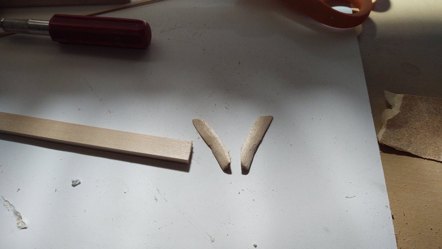
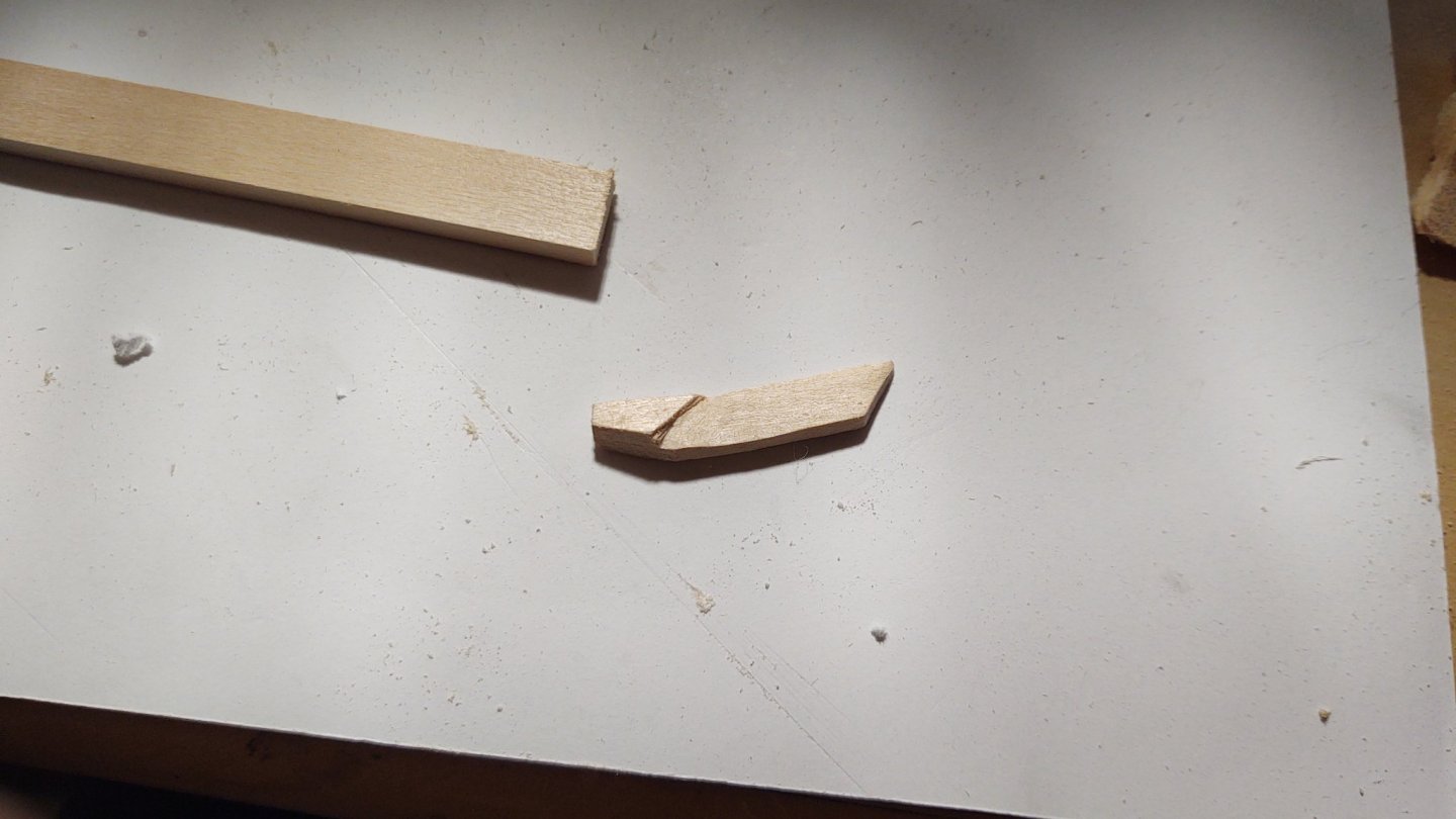
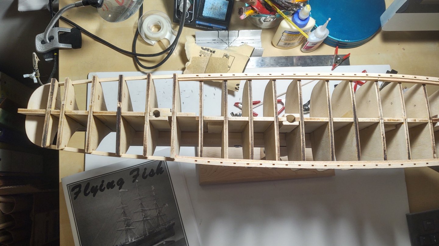
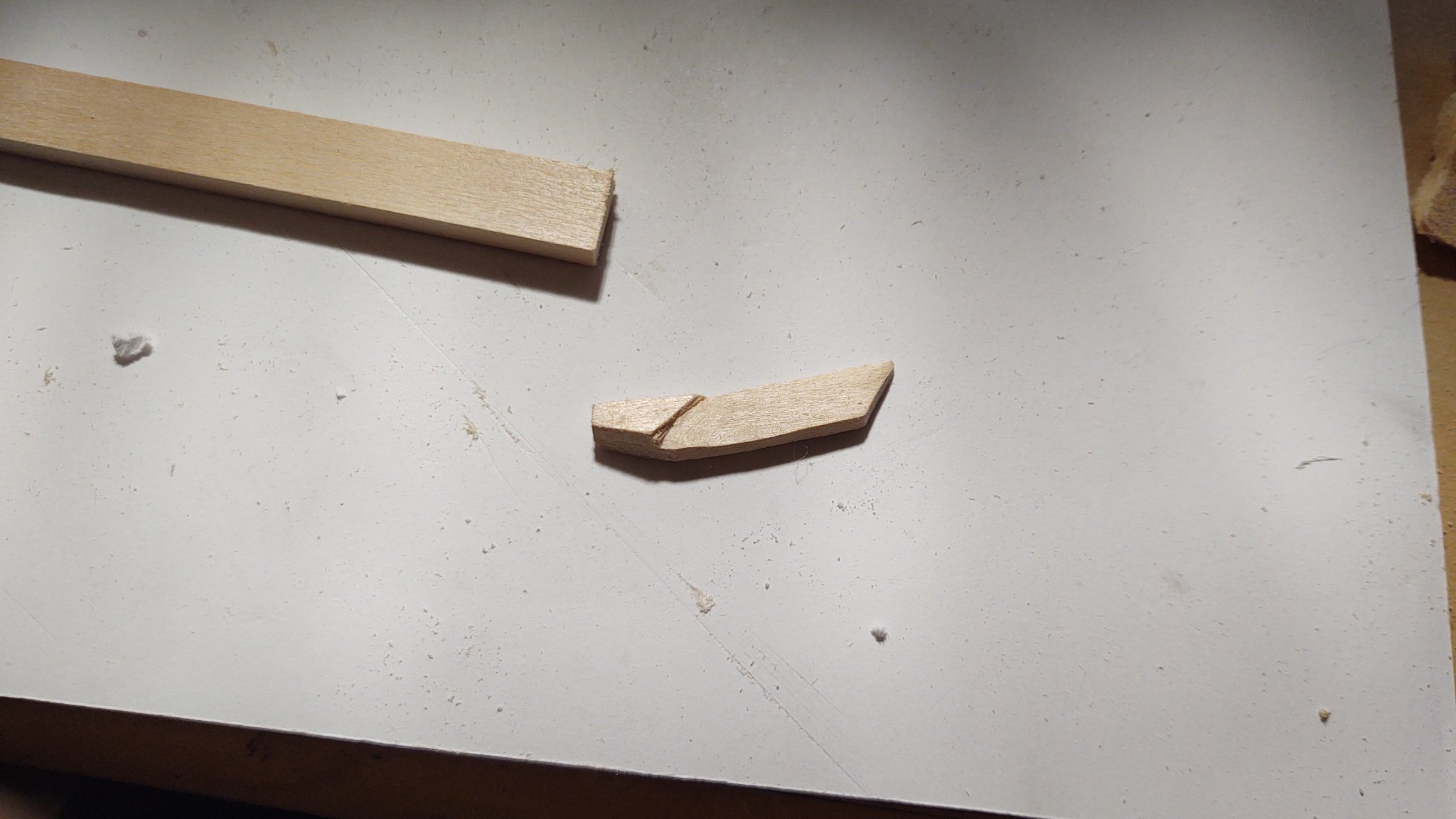
Just a brief update as it's been a crazy week. I carved the knightheads out of a piece of 3/16 by 1/2 inch wood. The instructions suggest carving the knightheads and putting a spacer in place so that the bowsprit will fit. This didn't square with either the plan dimensions or the suggestion (from the parts list) to make them from the 3/16 thick wood, so I carved them wider than called for on the plans, tapered them to fit the rabbet, dry fitted them on the keel, and then marked the path of the bowsprit (following the line of the keel). I then carved out a wider opening, in effect carving a one piece knighthead + spacer. These were CA glued in place, and I verified that the bowsprit will fit. Next will be the additional pieces that create the shape of the stern.
- Keithbrad80, Cathead and gieb8688
-
 3
3
-
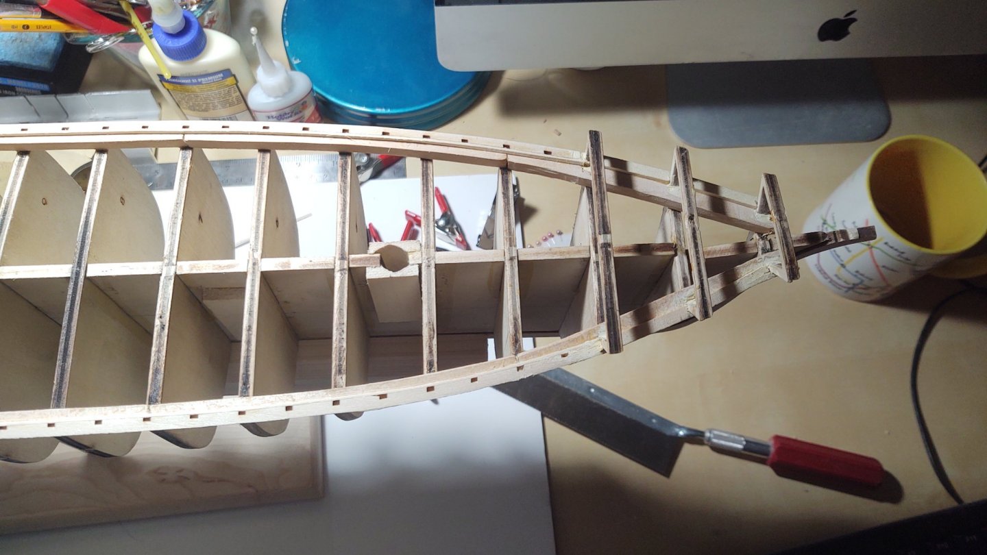
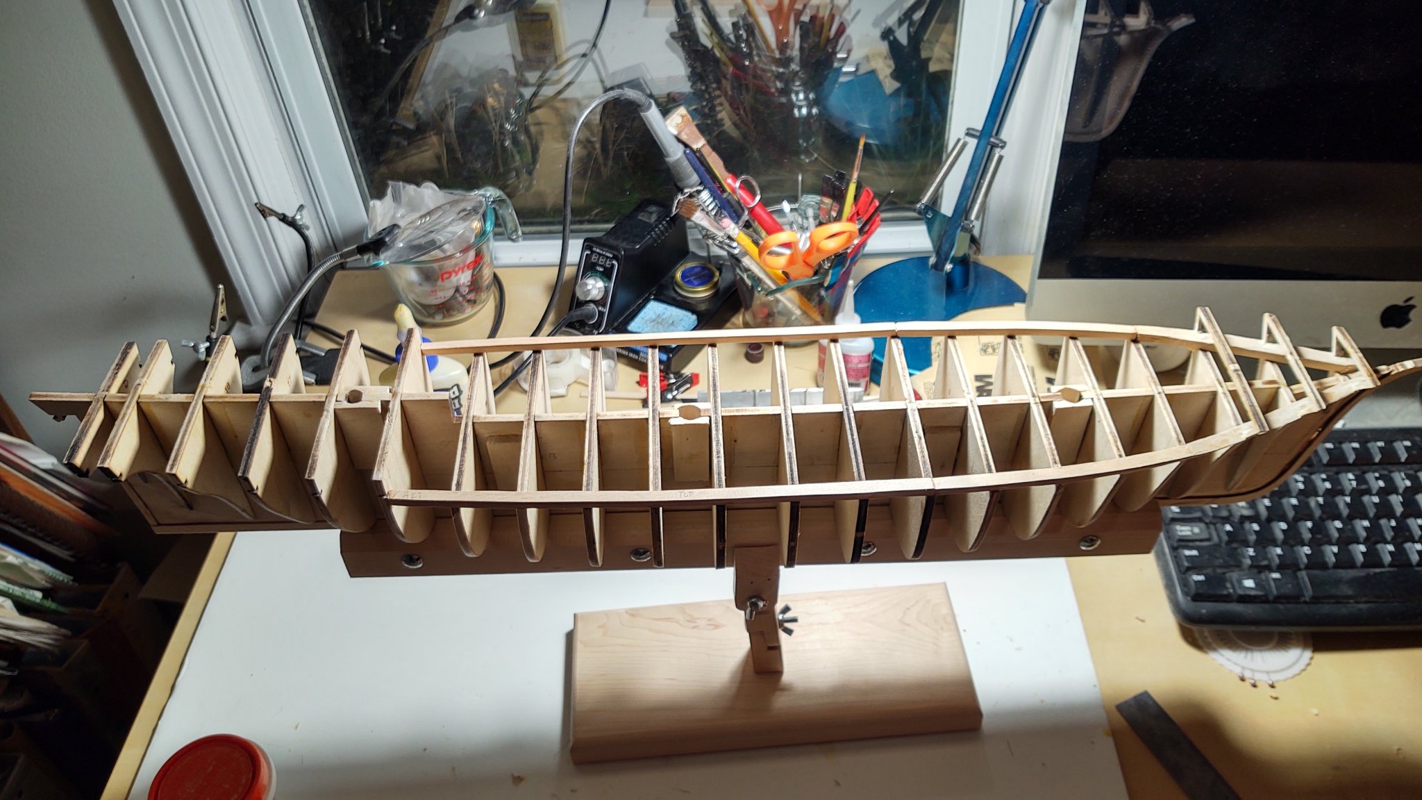
Update on the Flying Fish.
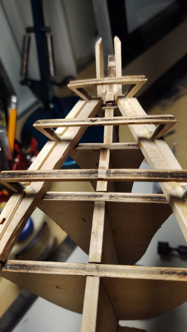
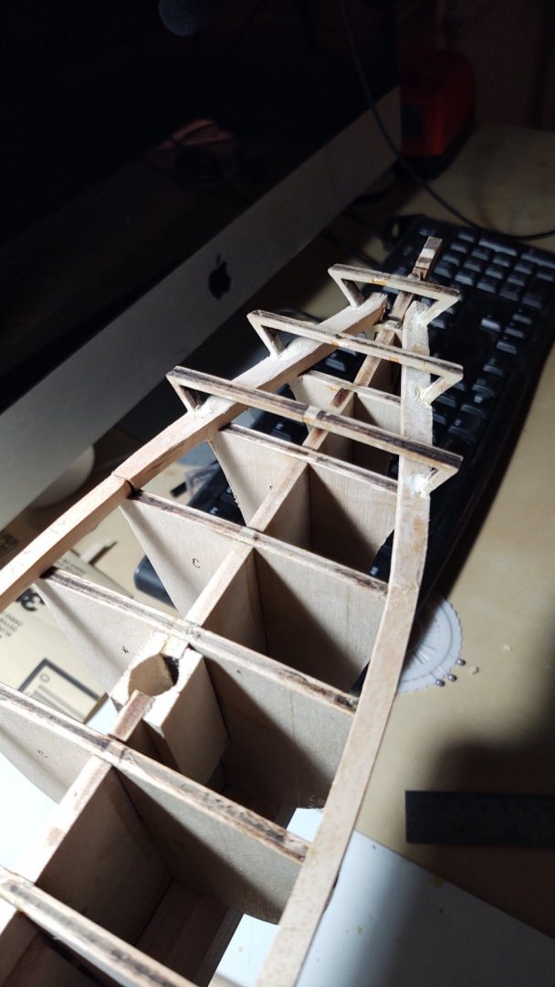
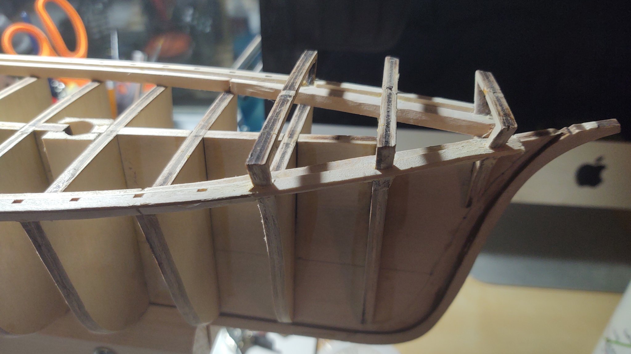
The next step was the installation of the planksheer. There are 10 pieces, 4 laser cut and six that need to be made from strip wood. The stern has two laser cut sections that completely fill in the section aft of bulkhead D on either side of the sternpost. The other laser cut sections (that include locations for the timberheads that form the main deck bulwark) run from bulkhead 15 forward to bulkhead 2. From D to 15, I used a section of 1/16 thick stripwood. It was sufficiently elastic that no steam bending was required, fitting into the slots and being held in place with CA glue. Forward of bulhead 2 (and functionally including bulkhead 2, I carved the planksheer out of another section of 1/16 stripwood, carving openings for the timberheads that define the forecastle. The remaining two pieces were a 1/16 x 1/32 section that was glued against the inner edge of the laser cut planksheer section amidships. Once in place, I sanded the top of the laser cut planksheer + stripwood section amidships to even it out (the 1/16 x 1/32 section was a bit wider than 1/16 in many locations). The last step was a bit of filler to close off some minor gaps.
One decision I made was to not extend the 1/16 x 1/32 strip under the forecastle. The sections are installed so that the inner edge of the laser cut planksheer segment is aligned with the inside edge of the timberheads under the forecastle, so that I could have (if I wanted) extended against bulkheads 2-B. However, I expect to put ceiling planks there, and concluded that (particularly if I want the ceiling planks to be wider than 1/32, it would look odd having the ceiling planks be wider than the planksheer. If I use 1/32 thick planks there, it will look the same. Ultimately, I just decided it would be better to cover that part with the ceiling planks.
Next steps are the rabbet piece aft under the planksheer and the knightheads, followed by the


- hamilton, Keithbrad80, gieb8688 and 3 others
-
6
-
Looks great, fantastic copper work!
-
On 12/26/2020 at 3:31 PM, Bruma said:
Mast detailing, painting and assembly.
All the lower masts are divided into two shells.
I glued them together, filled the gaps along the seams with putty and sanded the juncture in order to have a smooth surface.
The kit provides a good detail in this area but some parts are missing or simplified.
There are no futtock shrouds, for instance, so I placed hand made eyebolts for them on both sides of all three masts. Position, size and orientation are taken from Campbell’s plans.
The jackstay on main and mizzen masts are simplified and oversized, so I removed the original one (visible in the picture down below, close to the mizzen mast) and I recreate my own version.
Homemade eyebolts are fitted in predrilled holes (mini drills bits proved to be really useful along the entire build), glued in place and fitted with relative bars. The bars are made of spring steel (I hope it is the proper name in English). They maintained their shape and are perfect for the job.
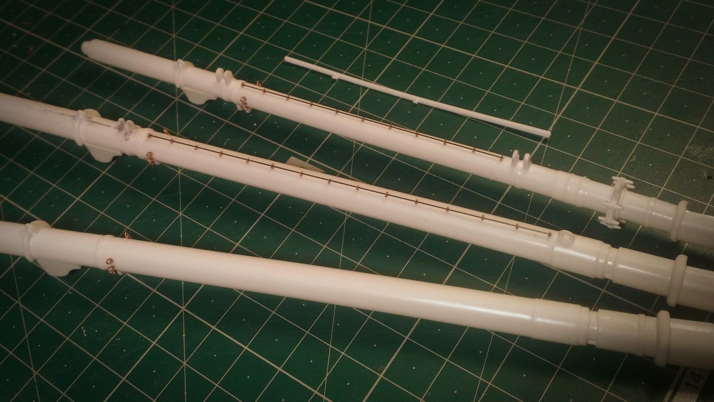
I have also added the eyebolts at the mast base, they were absent in the kit.
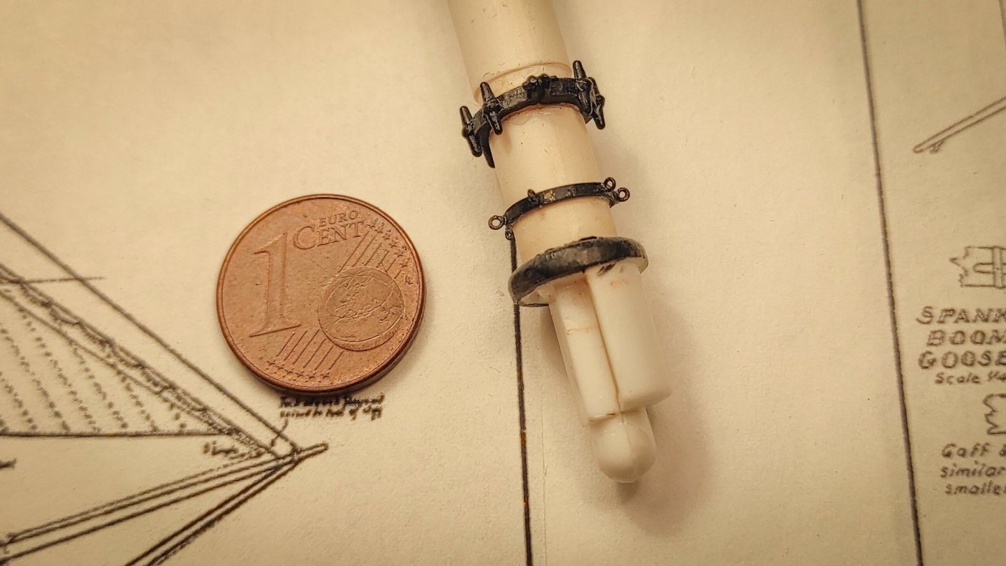
In the above picture it’s also visible the painting job: a first coat of matte white was followed by brown oil filters in order to enhance the shadow and break the white monotone.
The blacks are all tire black, whit gray dry brush.
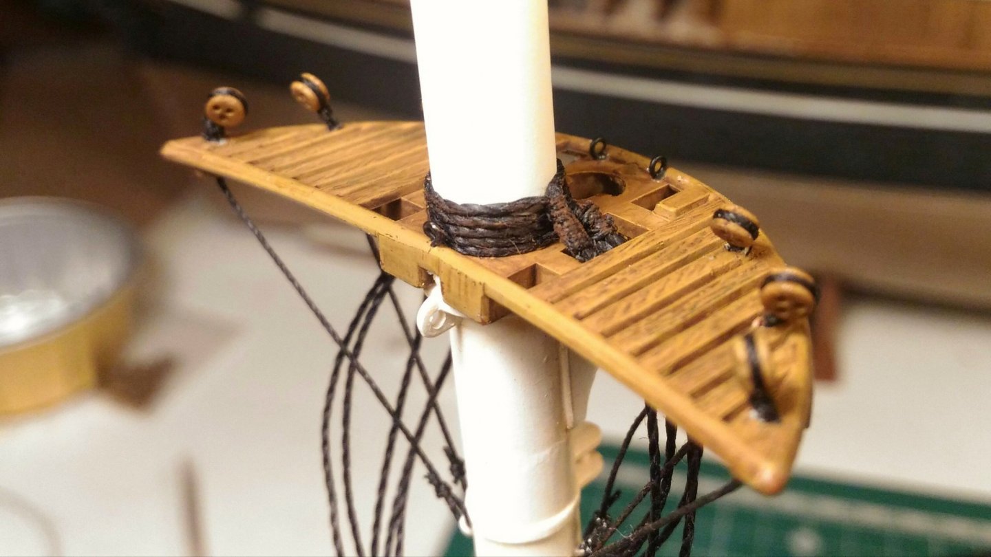
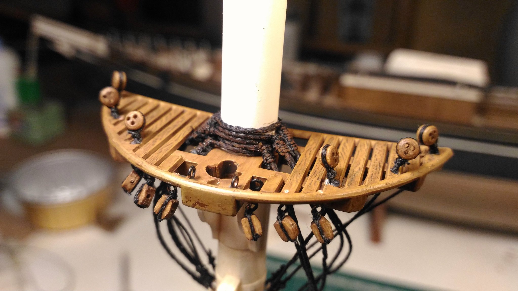
All the tops were modified. The kit provide plastic shrouds and to fit them the tops have dedicated holes.
They need to be filled with putty, sanded e prescribed. The excess of plastic around the holes needs to be removed. New holes were drilled for the futtock shrouds, following the right position indicated by Campbell’s plans.
Even if I think this part was improved by my effort, I now think that I should have done more. They are still too thick and the lower metal frame should be added. But now it's too late.
Many times along the build I have had to decide if “it was good enough”, and usually I made the wrong decision.
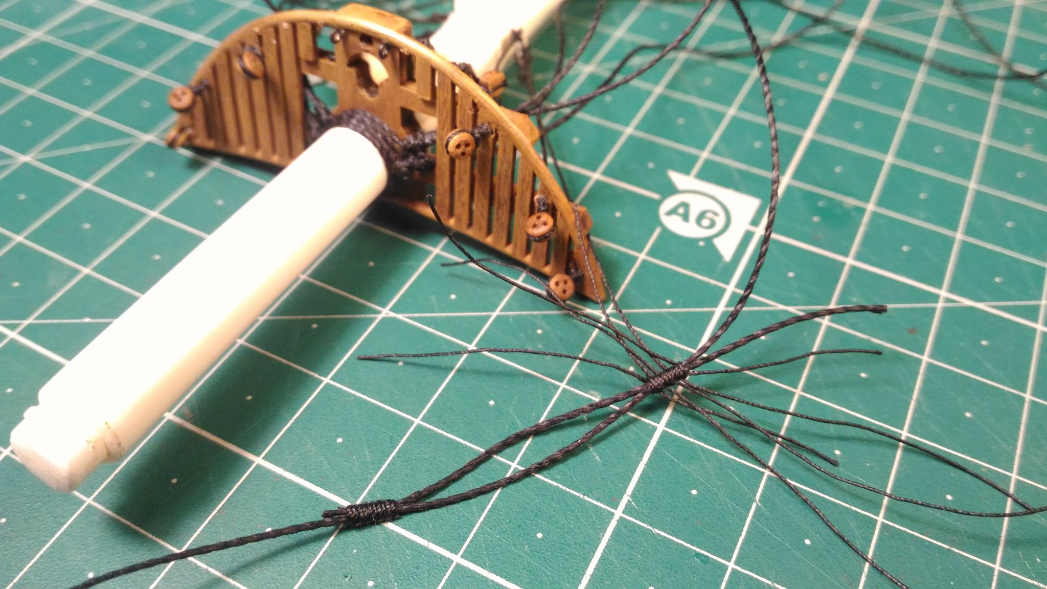
Anyway, I thought it was easier to rig the shrouds with the masts not glued on the hull, so I started with the futtock shrouds and the main shrouds.
After many tests (I had no experience in rigging at all...) I found my way, here you can see the process in the making:

And here is the final result:

The black of the shrouds was attenuated by brown pastels.
In the last images eyebolts and blocks are also visible. I decided to install them now, with plenty of space to operate.
Enough for today.
I hope you like the updates and I wish you happy holidays!
What beautiful work you have done throughout the build. Not sure why, but the top just really caught my attention, particularly the way you made plastic part look so realistic. It is going to be a fabulous model when it's done.
I have a particular soft spot for the old Revell Cutty Sark. My grandfather made two of them when I was a boy and he was living with us between when his wife died and he eventually passed away in '69. Sitting next to him while he worked on those models (and a Revell 1:96 Constitution he was working on when he died) was probably what got me started in modelling.
- shipman, FrankWouts, Bruma and 2 others
-
5
-
The hull looks great, nice clean lines. The bow on shot is really great, it looks just like the photos you see of clippers (and early 20th century windjammers) in drydock.
-
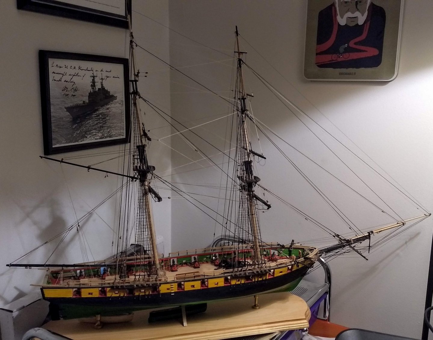
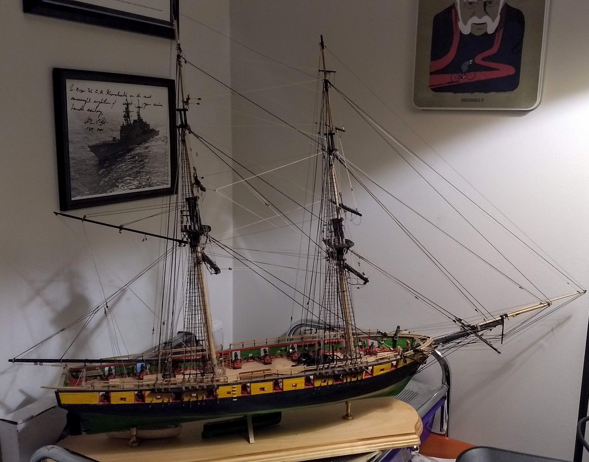
A bit unrelated, but the case for my US Brig Niagara arrived from BlueJacket. I need to find a glazier to buy and install the glass, but it will be nice to protect the ship (photo below).
You don't realize how big these things are until you get a case the case. The ships are so delicate, but the cases aren't.
- Papa, BobG, Vladimir_Wairoa and 4 others
-
7
-
53 minutes ago, Keithbrad80 said:
Very nicely done! I had a really hard time with the water way under the forecastle, but yours looks great!
Bradley
Thank you. They were a real pain to cut, but he biggest problem was that I broke every single one of the bulkhead extensions for the forecastle at least once. They are all probably 10% CA glue now.
This is proving to be great practice for my eventual plan to scratch build RRS Discovery (if the plans ever come post COVID-19). The hull form is pretty similar and as you know, the plans show the actual ship rather than the model in many places, particularly with regards to the hull cross sections, which will be the case with Discovery.
-
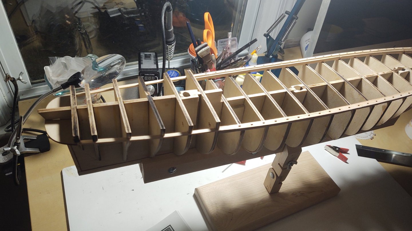
Thank you all for the good wishes. A bit of delay because I've been working on repainting part of the house, but here's an update.
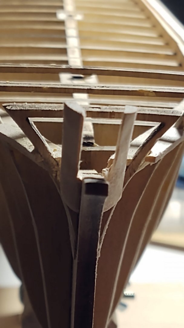
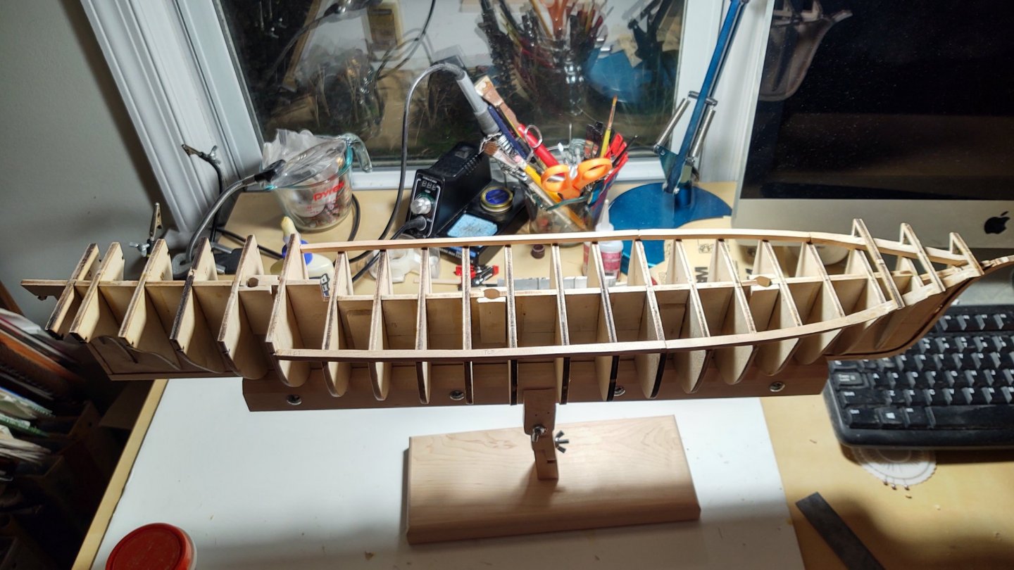
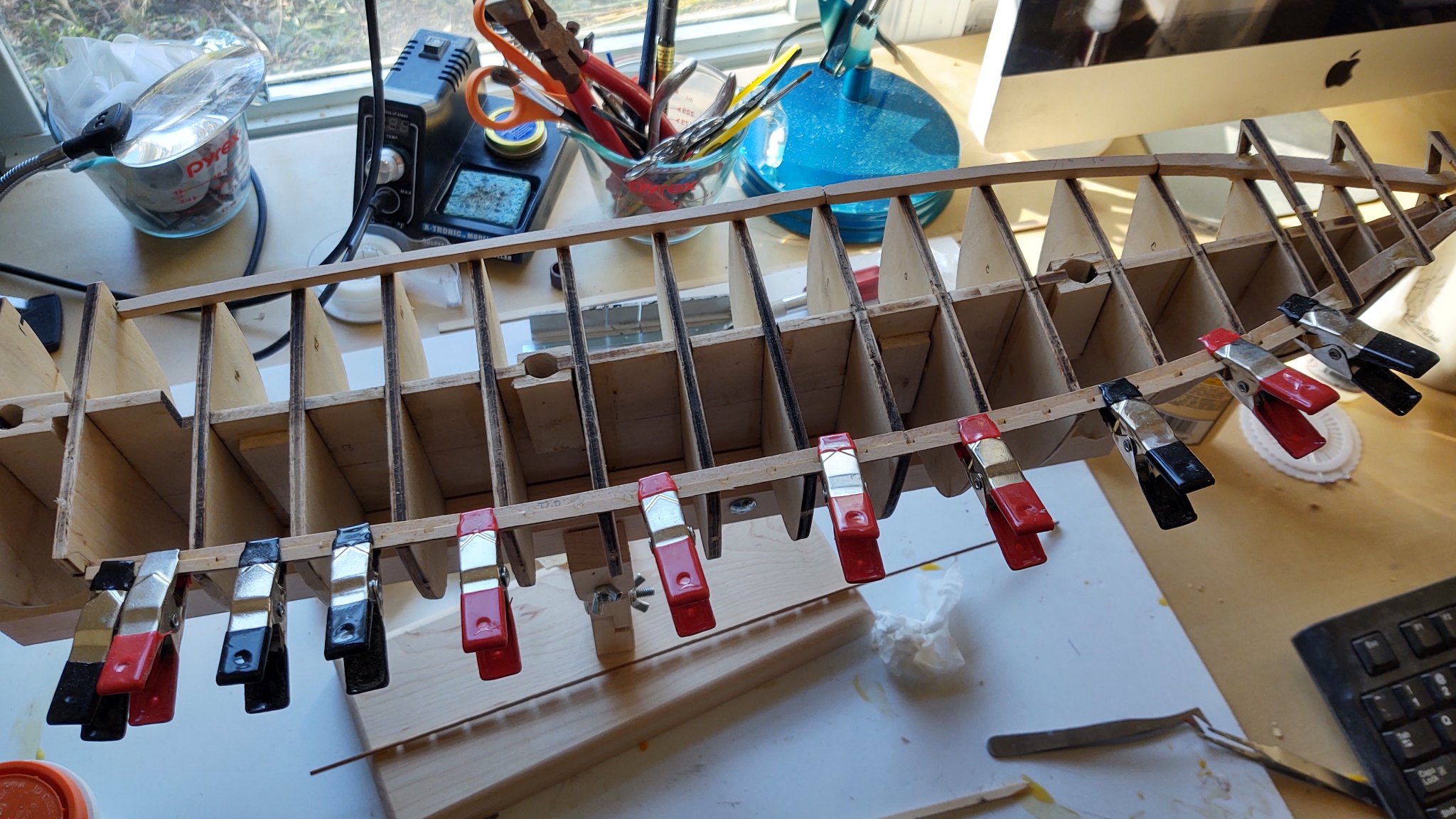
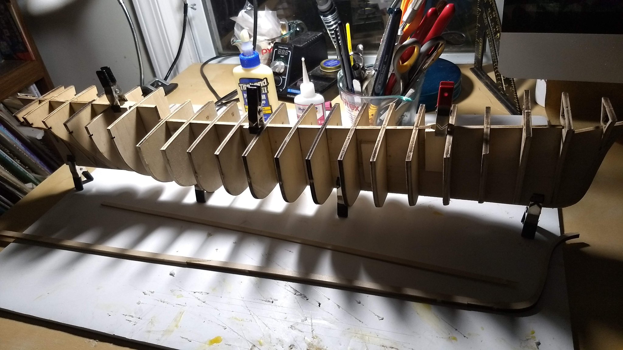
I've since installed the waterway. The instructions suggest carving it from a piece of 3/16 by 1/2 by 24, with the inner edge 3/16 in from the edge of the bulkheads, and leaving sufficient material to shape the outer edge to follow the curves of the bulkheads as if they were continuing upwards. Forward of bulkhead 3, it needed to be carved to fit around the bulkheads themselves.
As a practical matter, it was necessary to construct this in 3 sections, the first running from bulkhead 15 to 7, the second from bulkhead 7 to 3 and the final one from bulkhead 3 forward. The last piece was so short because of the necessity of matching the outward flow of the bulkheads where the forecastle will be. Once installed, I filled some gaps where I carved around bulkheads 2, 1, and B with Elmer's Wood Filler.
Next step is to install the planksheer and the knightheads.
- Duanelaker, Rudolf, BobG and 4 others
-
7
-
Very nice. I like the way that the deck color turned out. Are the tree nails. A toothpick end (let alone the body) at 1/96 is 3 scale inches. My guess is the only way to simulate at scale is going to rely on ink rather than wood.
-
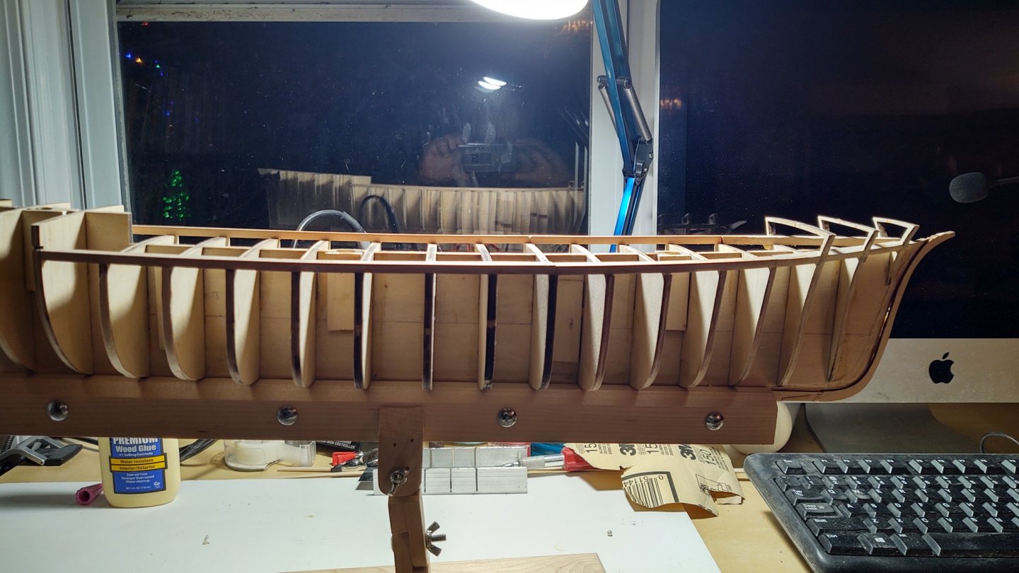
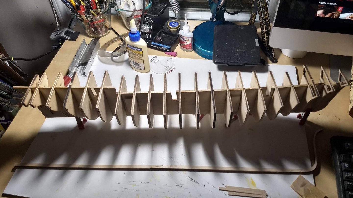
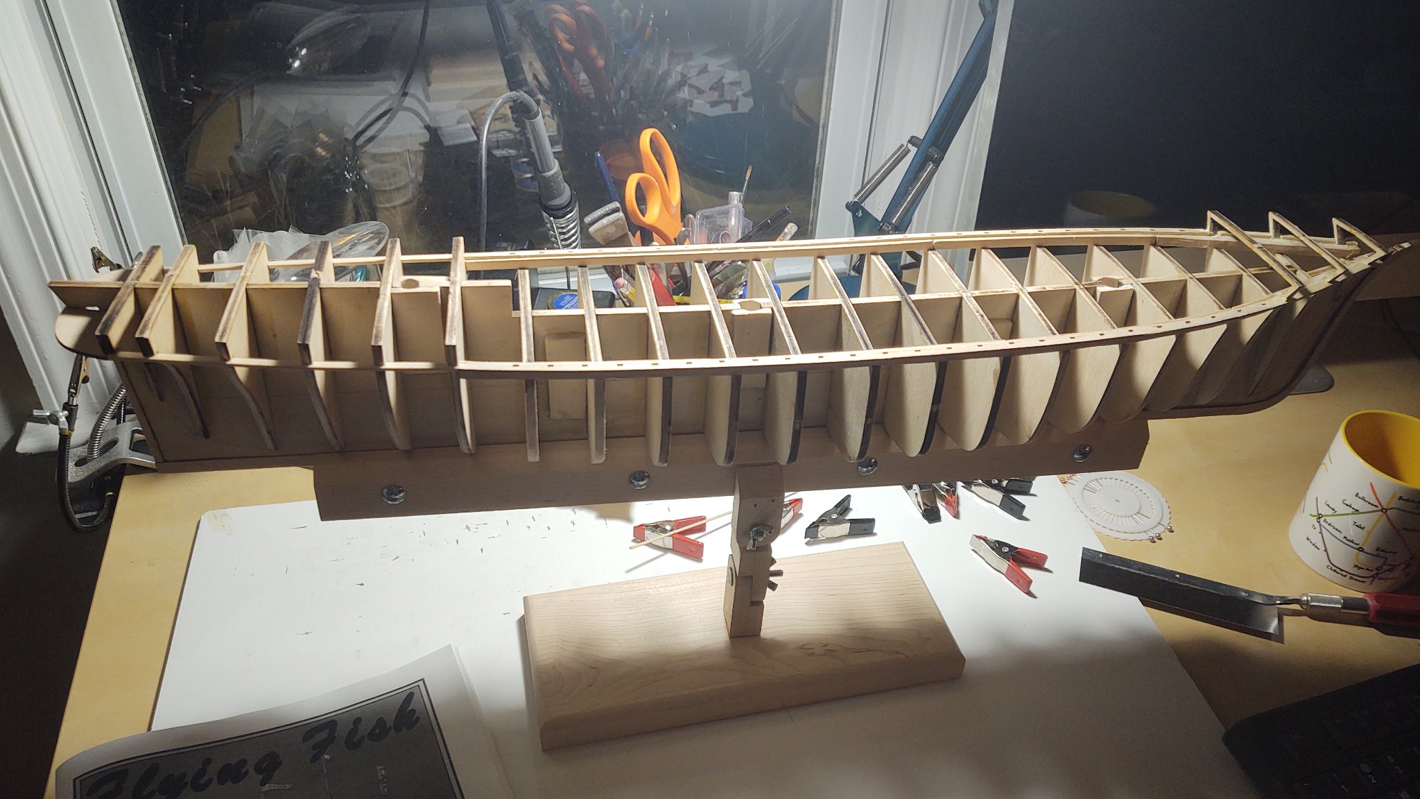
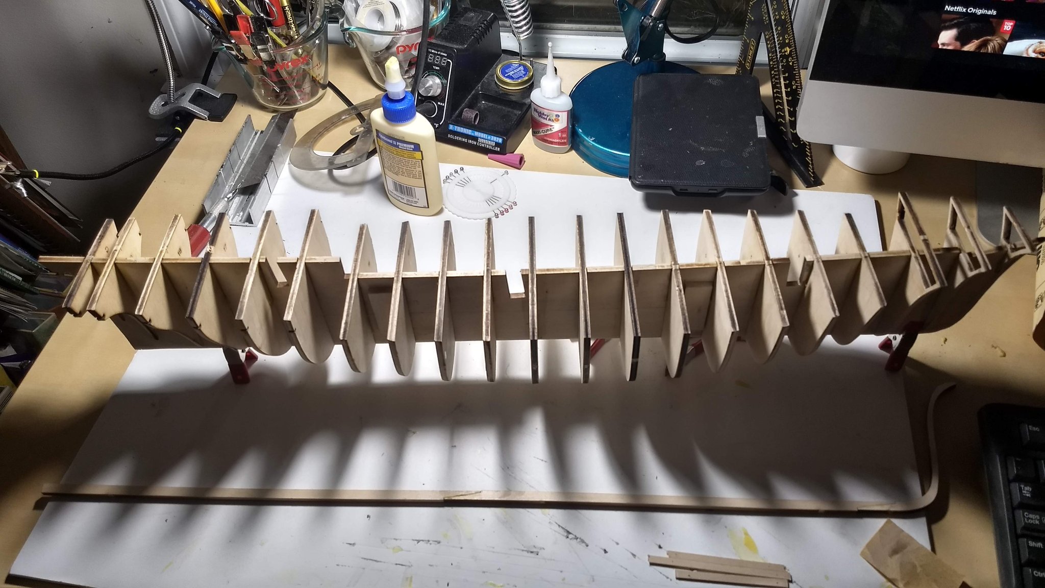
Step 1 more or less complete. Main keel cut out and assembled. Rabbet cut. Bulkheads cut, cleaned and faired. Mast supports cut and in place. Lower keel ready to be glued in place.
On the whole pretty painless. I added extra stiffeners (scrap wood) over the keel joints for strength and to help ensure that it remains straight. I needed four shims - two on each side on bulkheads 13 and 14, otherwise it was fair and true.
Two things I've been thinking about lately. First, the ship was 'coppered' with Muntz metal and it appears that it is possible to get brass tape in the same basic sizes as copper. While shiny, it may look more like Muntz, so I'm going to try to get some. It isn't as common as brass tape, but there is a glass studio near here and they may be able to get it. Second, I've been reading Steven Ujifusa's "Barons of the Sea: and their race to build the world's fastest clipper ship". In it, we learn that Donald McKay wanted to paint the Flying Fish green rather than black. This pleases me, and I am thinking about painting her a dark, almost British Racing Green to comport with McKay's original vision. I'll probably change my mind before I start painting, but that green with black highlights would make a really lovely vessel.
George

- Duanelaker, schooner, gieb8688 and 4 others
-
7
-
Sorry to hear that. Not ideal but better, I suppose, than the alternative.
-
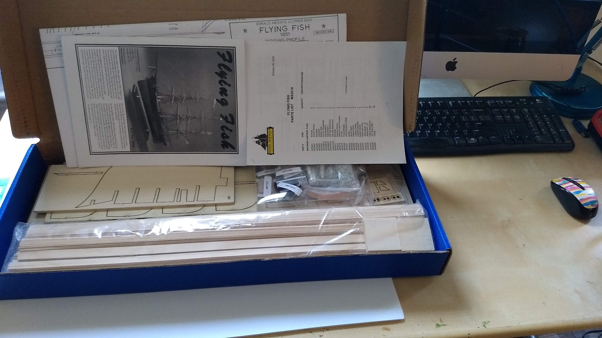
Hello everyone. This is my first build log and it is for the Donald McKay designed extreme clipper Flying FIsh. The ship has been described well in other logs, but the summary is here: (wikipedia and http://www.bruzelius.info/Nautica/News/BDA/BDA(1851-11-04).html)
Built: 1851, East Boston Shipyard
Length Overall: 220 ft
Length between perpendiculars: 210 ft
Length at keel: 202 ft
Maximum beam: 40 ft
Tons (OM): 1566 tons
Originally owned by the firm of Sampson and Tappan of Boston. She was wrecked in Fuzhou in 1858, sold to a company in the Phillipines, and renamed El Bueno Suceso. She eventually sunk in the South China sea.
Flying Fish was "coppered" with Muntz metal rather than copper (similar to the Cutty Sark). You can't get Muntz metal tape, alas, but I may try to do something to make the plating more consistent with muntz.
I had not originally intended to do this ship. Having recently completed the US Brig Niagara, my plan was to make a scratch model of the RRS Discovery, but COVID-19 put the kibbosh on that for now, as the only plans available are at the Royal Museum Greenwich and they went back on lockdown while processing my order. I can't imagine going through the winter cooped up in the house without some kind of project. If and/or when the plans for Discovery arrive, I will likely have two projects going. But, I've decided that this is a feature, not a bug. While I'm in the doldrums of say ratline tying with one, I'll be in the doldrums of planking with the other. So, while it means that both projects will take longer, I'll be able to at least alternate some of the tasks. And, there will likely be a couple of months of work converting the builders plans into a usable POB design for the Discovery, so, who knows, depending on COVID vaccine timelines, it may be enough to make serious progress on this ship. That's what I've told myself anyway.
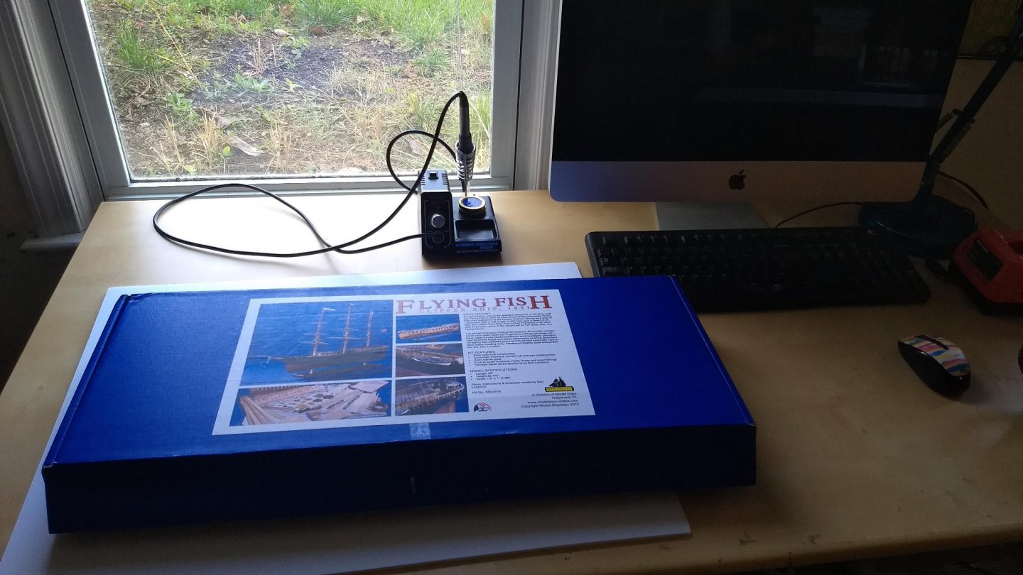
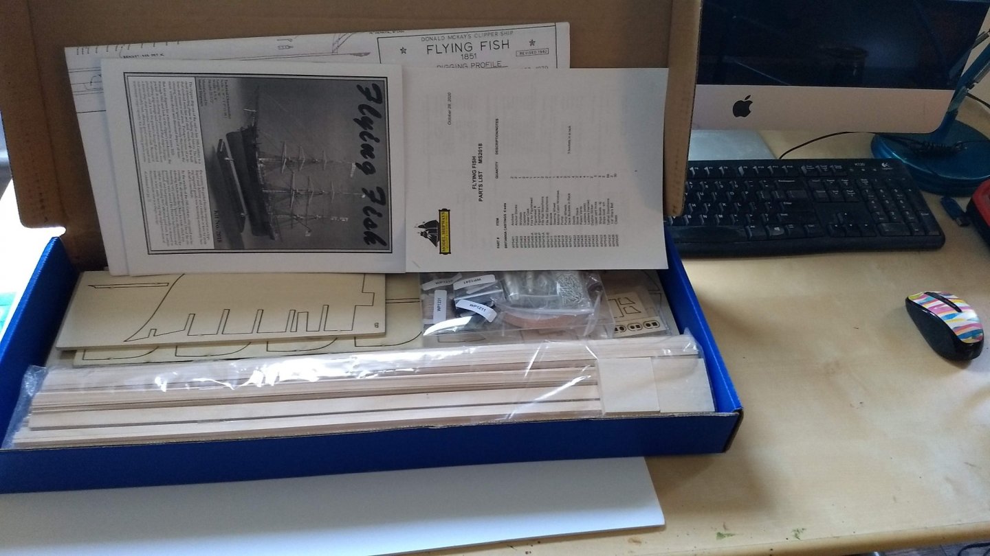
So, I believe tradition for the first post of a kit build log is a picture of the kit ready to go, so here are mine. Let the construction begin:
-
2 hours ago, shipman said:
Dr PR, thank you for your explanation. Once you understand this stuff, it's surprising how simple and logical it becomes.
Can't remember seeing a snow rigged model.
US Brig Niagara. https://en.wikipedia.org/wiki/Brig_Niagara. Model Shipways makes a model. There are a bunch build logs on the site.


Flying Fish by gak1965 - FINISHED - Model Shipways - 1:96
in - Kit build logs for subjects built from 1851 - 1900
Posted
Soon. I still have to get the timberheads in place and some work on the stern. I also think I'm going to paint the waterway and planksheer before I put in the timberheads or the main hull planking.