


Ilhan Gokcay
-
Posts
574 -
Joined
-
Last visited
Content Type
Profiles
Forums
Gallery
Events
Posts posted by Ilhan Gokcay
-
-
-
Thanks Vince, I will share the plans when they are ready.
I use a CAD program (2D) for drawing. It's QCad (https://www.qcad.org/en/) easy to use(and learn) and effective. It's also not expensive.
For the line plan I used "DelftShip" and transferred the file(dxf output) to QCAd. The free version of "DelftShip" is sufficient for my purpose.
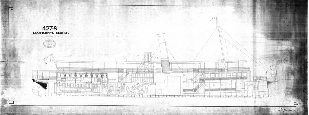
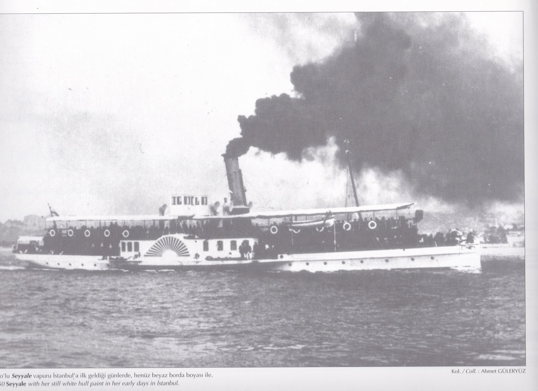
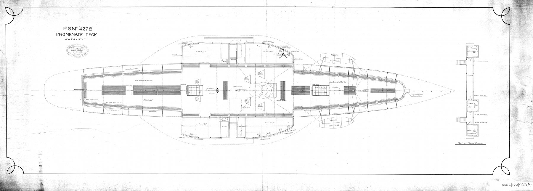
She is built by Fairfield Shipbuilding Company, Glasgow in 1903, 52m long ferry.
- druxey, trippwj, Mirabell61 and 1 other
-
 4
4
-
Vince, I appreciate very much your detailed explanation.
I see I'm going the same road as you, I'm also researching and develeoping plans of a British built Turkish paddle steamer ferry for Bhosporus/Istanbul.
I have a couple of books about steam ships but not much info about the construction of a paddle box and beams etc. (And also usually photos and drawings from Internet.)
That's why I keep asking questions.
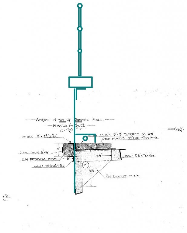
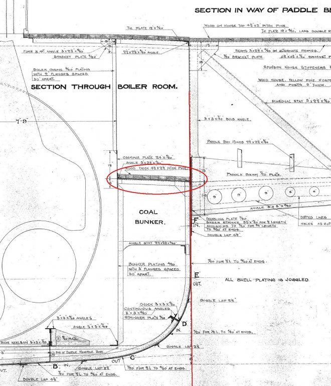
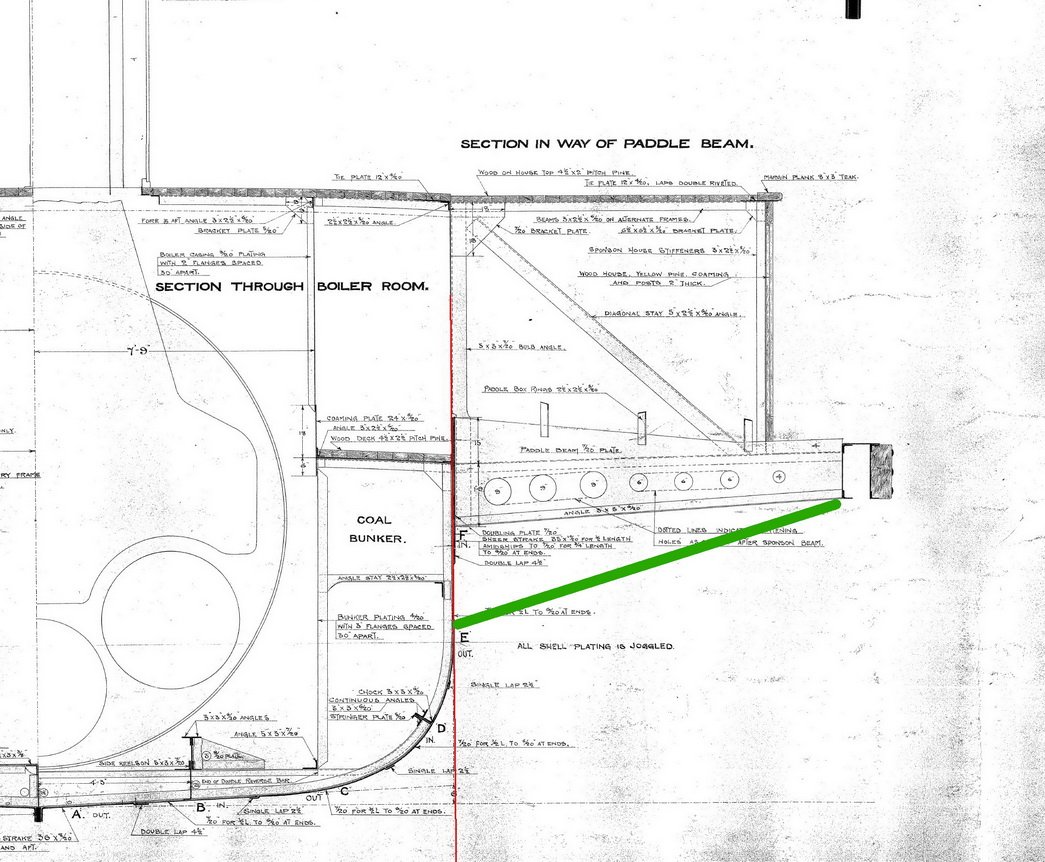
But it is getting clearer. My last question would be about the beams of the paddle decks. I assume that their positions are where the stays are.
But they are not like the two main atwartship beams of the paddle box (like the one on the cross section drawing), aren't they.
Can they be simple I beams or angles ?
Attached some views of my plan.
Regards-1-Gemi-15-Spnsn1_resize.thumb.jpg.42219cd789a7351858b3be1fbedd630d.jpg)
-1-Gemi-15-Spnsn2_resize.thumb.jpg.4d5321e74e1d4e5c412d3191493a3050.jpg)
-
Hey Vince thanks for the info.
I believed that the stays (I call them "support") are to support the beams (I call them "sponson") and the paddle box. Interesting.
So there are beams with no stays where I marked red as the one shown on the cross section plan.
Then next to these beams there are stays very close to them. Do these stays end simply at the outer edge or are there again beams to hold these stays and also support the paddle box deck.
- druxey and VinceMcCullough
-
2
-
Hello again,
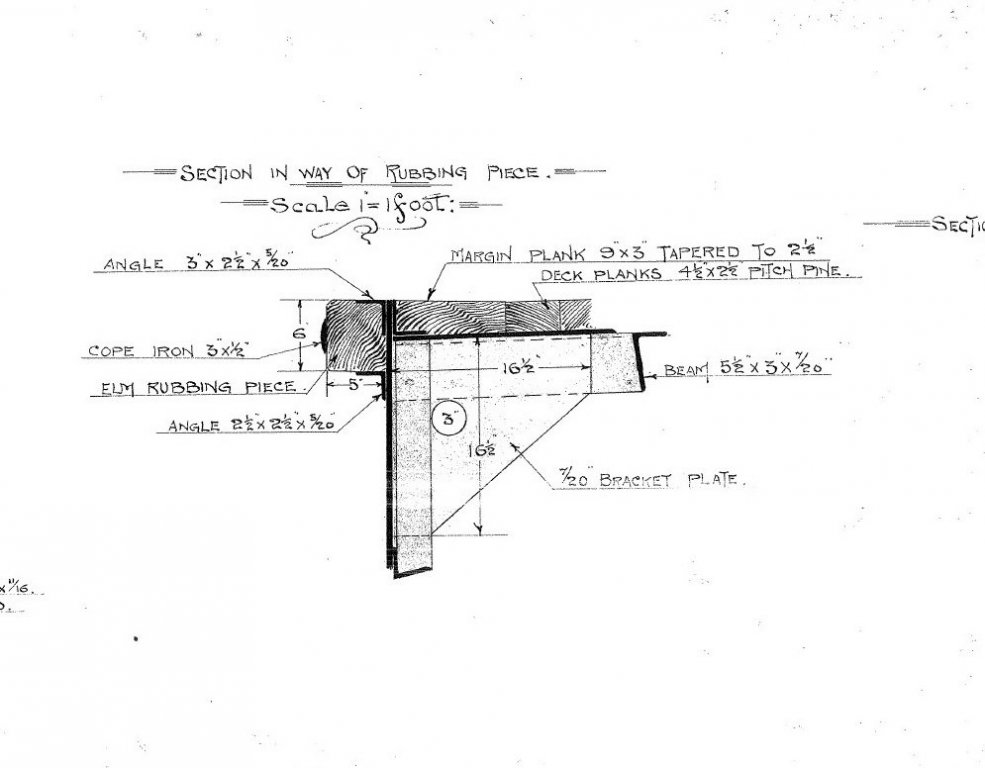
I'm still working on the drawing of my PS. Altough I have/collected much of information I came again to a dubious point and ask for opinions.
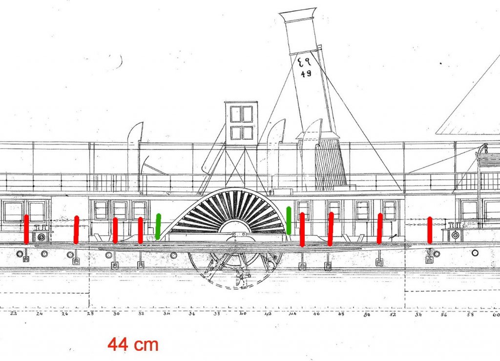
I marked the positions of the sponsons with red on the side view plan, I think there should be also a sponson where I marked with green as this is where the paddle box sits. I'm not sure if it is true what I think. Should there be a sponson or otherwise how is it constructed.
I have also a cross section drawing where there is no support shown for the sponson. I'm not sure if there are supports for all of the sponsons or not.
And if the other shorter sponsons are like the one on this cross section drawing.Thanks in advance
Ilhan

-
Hey thanks for the clues.
I do interpret the construction as this. Can this be possible.
( The height of the half bulwark is around 45-50 cmm. )
-
Thanks again for the helpful comments.
Regarding the same ship I have another point which I need to clarify which is the constuction of bulwarks.
Unfortunately on the drawings it is not clearly shown.
My main concern is that there are no stanchions shown on any drawing. Can this be true that the bulwarks are steel plates without any support. The steering chain covers are also shown flush with the bulwarks that there is no room for stanchions.
I couldn't find any similar vessels which have such bulwarks.
Thanks again in advance
Ilhan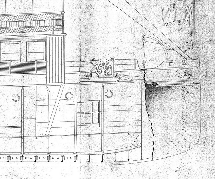

-
Hey Steve thanks for your opinions.
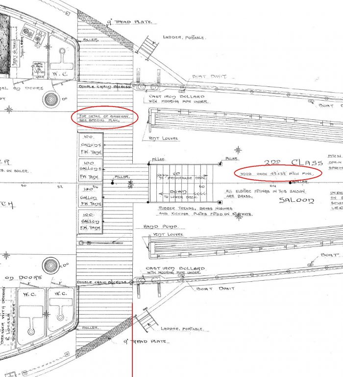
Unfortunately there is no such a drawing(detail of the gangway). I suppose as you said that this a seperated deck section for passengers to step on.
But why a seperate drawing if not that complicated ? Why seperated deck section if level with the deck ? How does it look like ?
Don't the similar vessels have such a gangway ?
Questions, questions,..
-
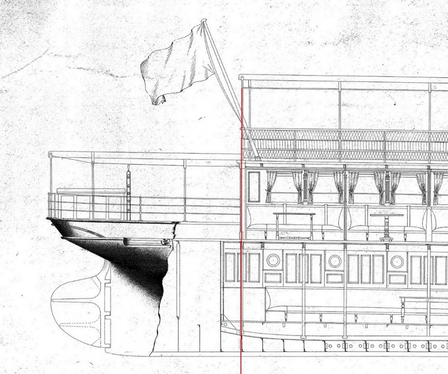
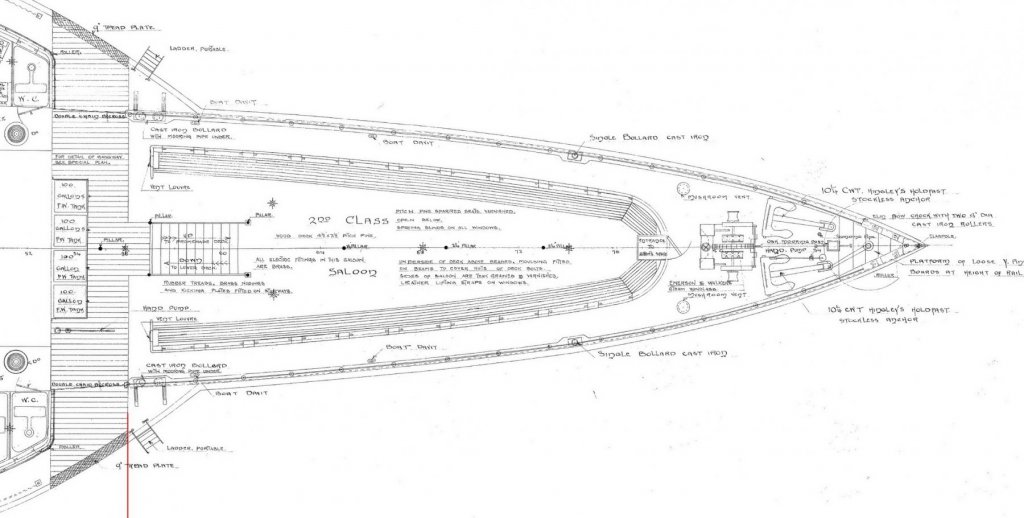
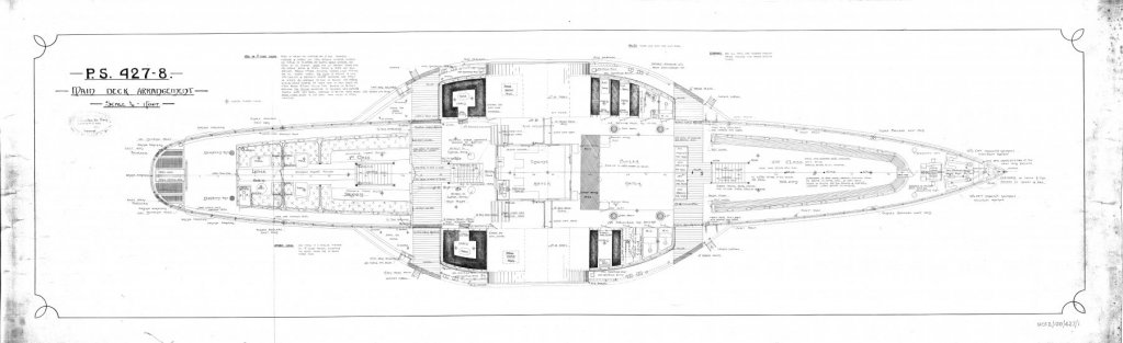
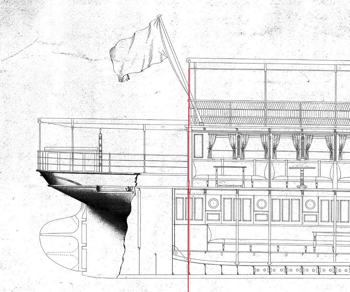
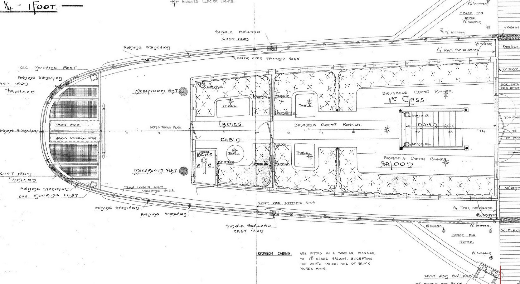
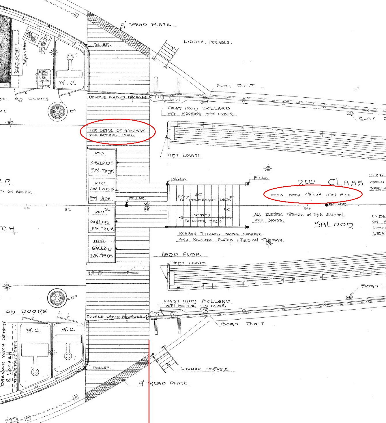
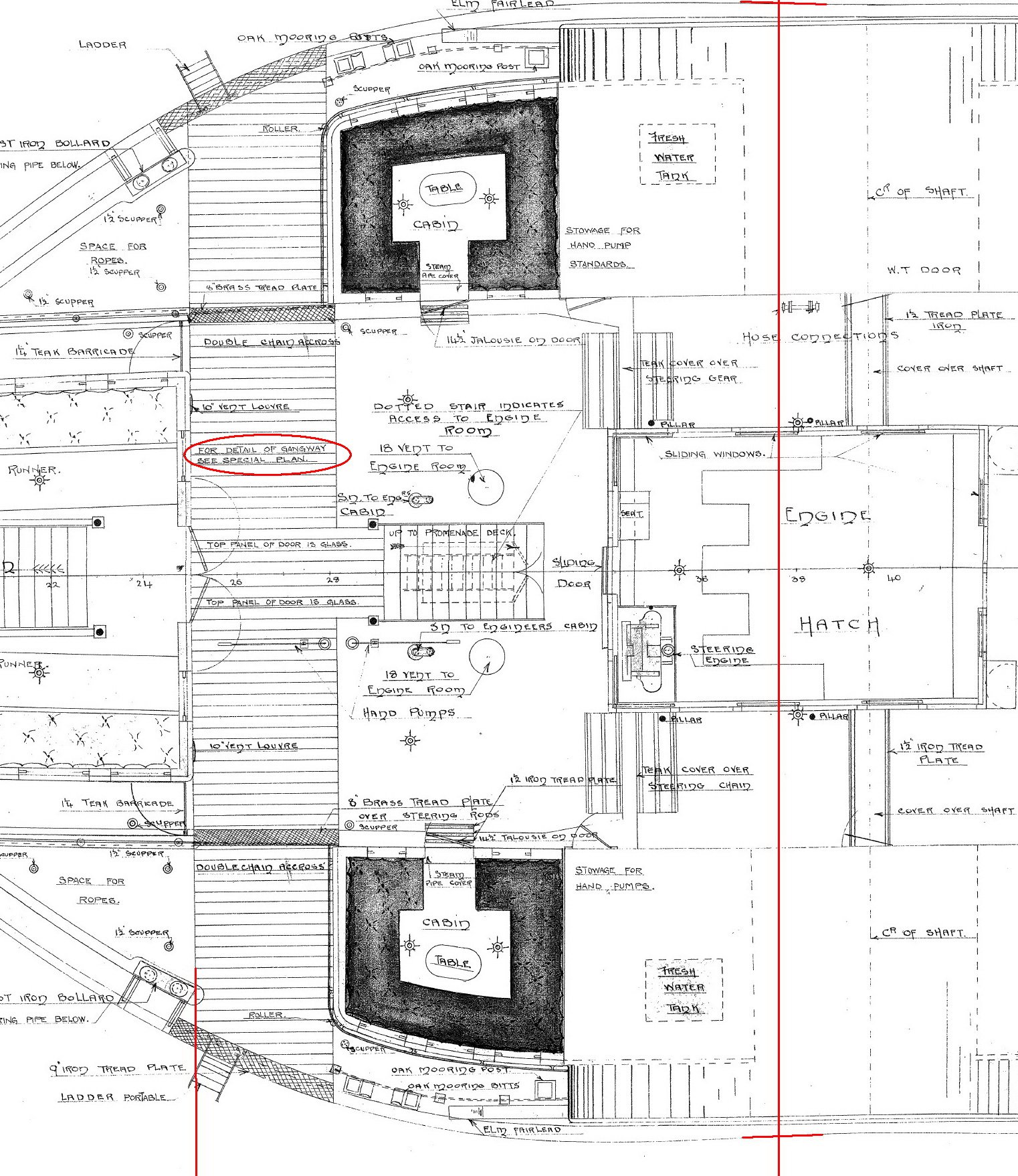
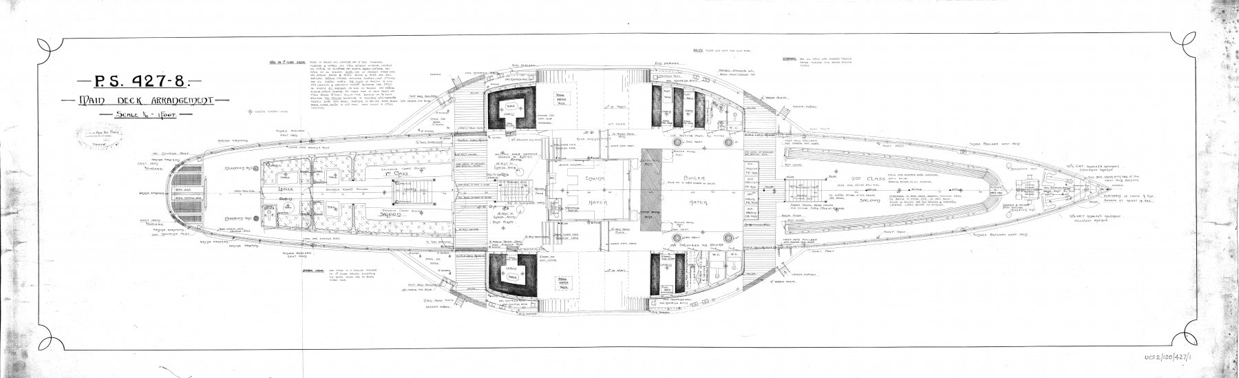
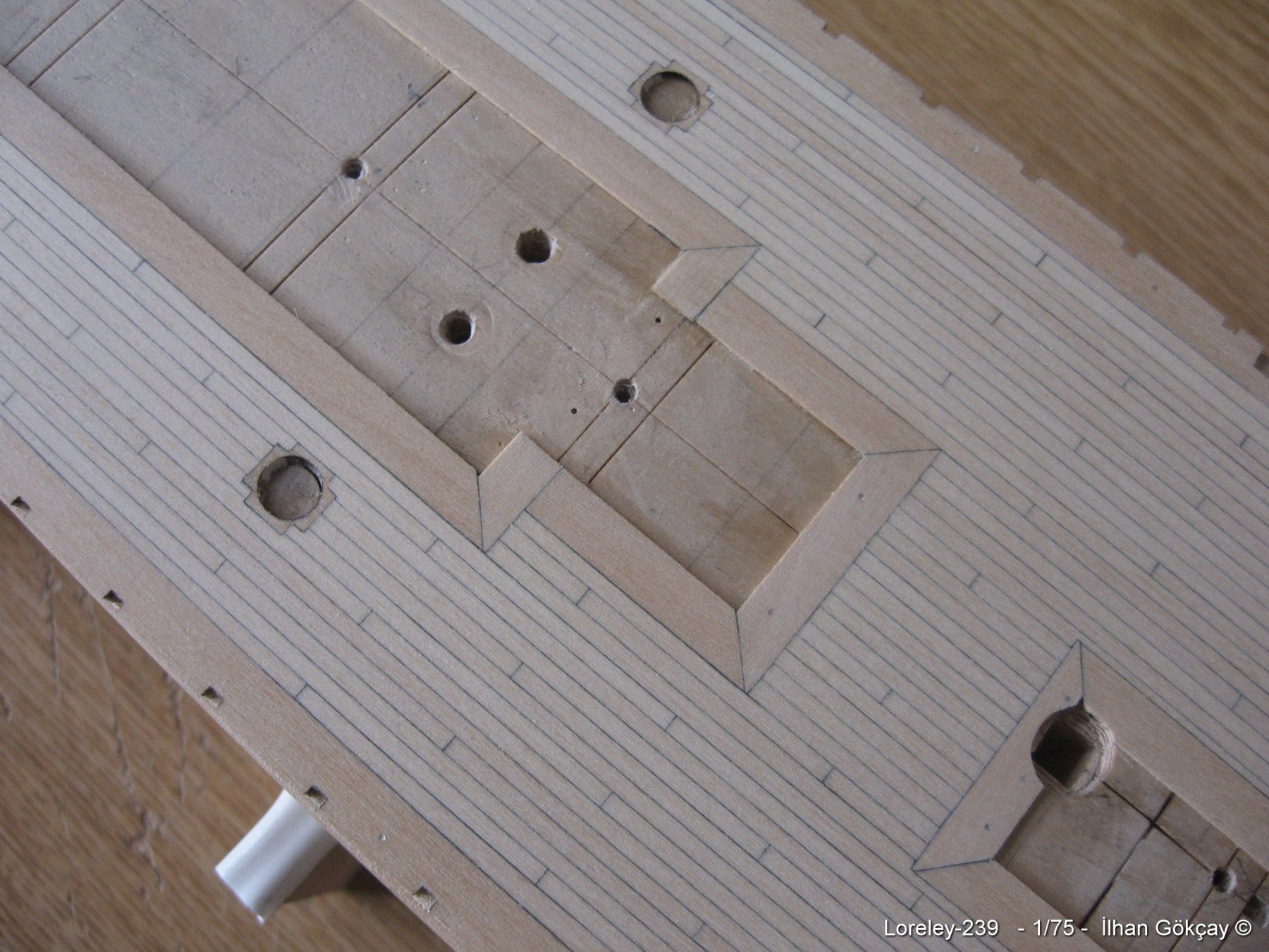
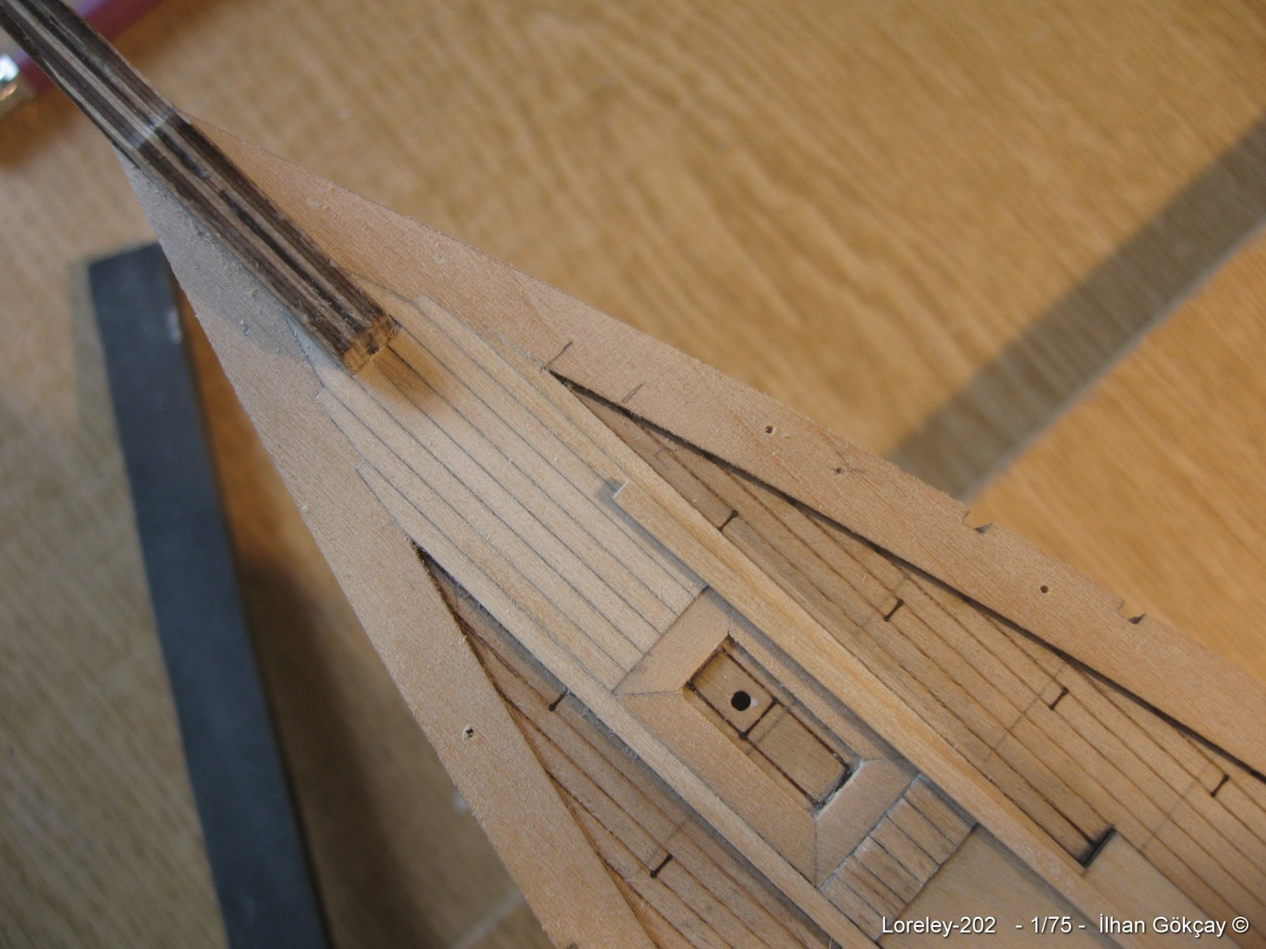
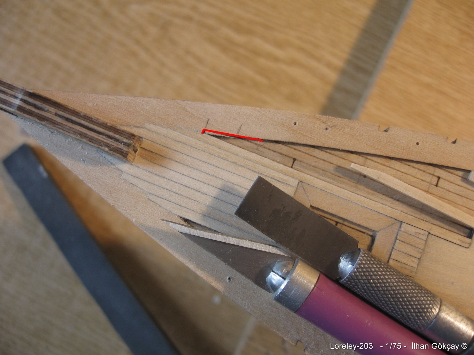
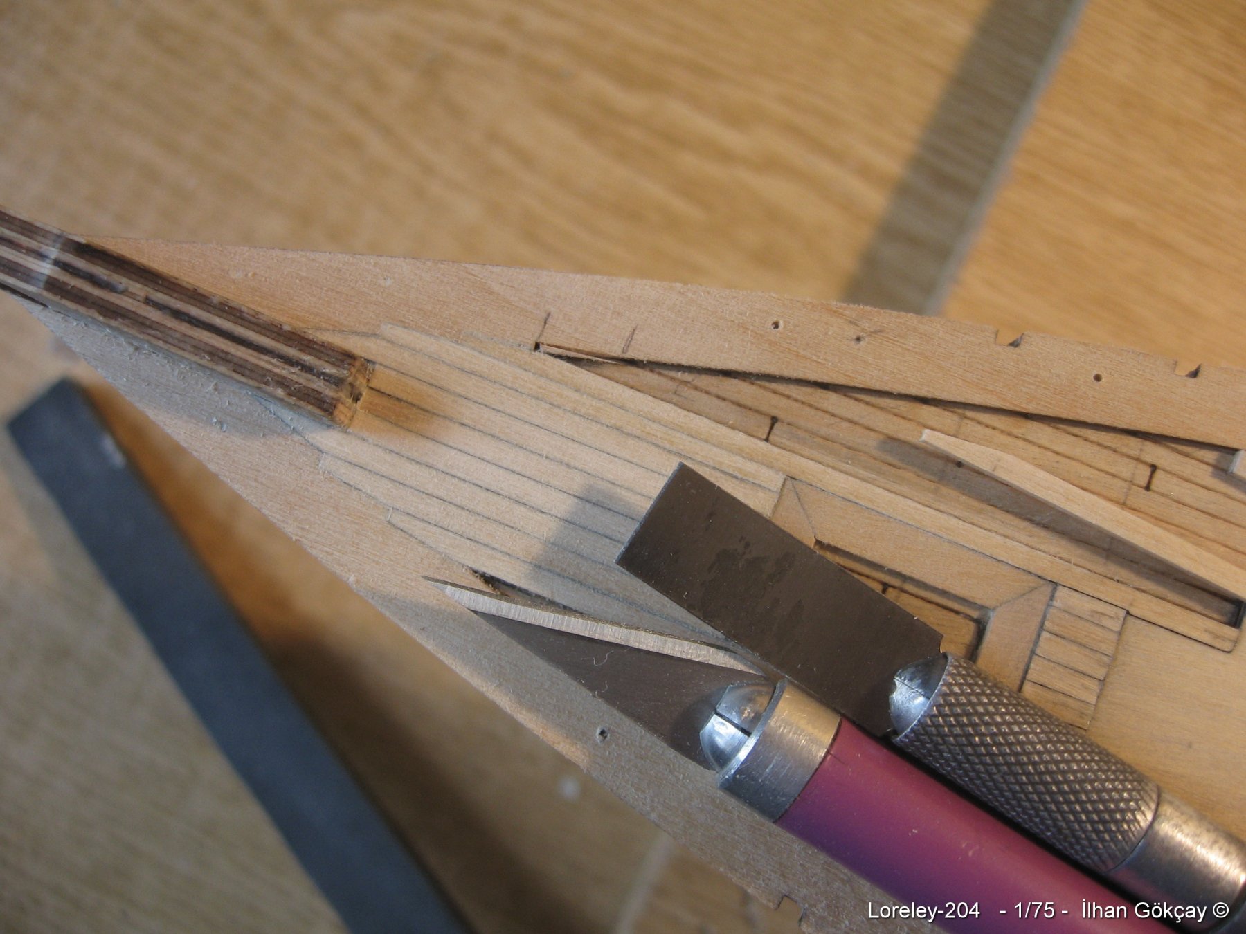
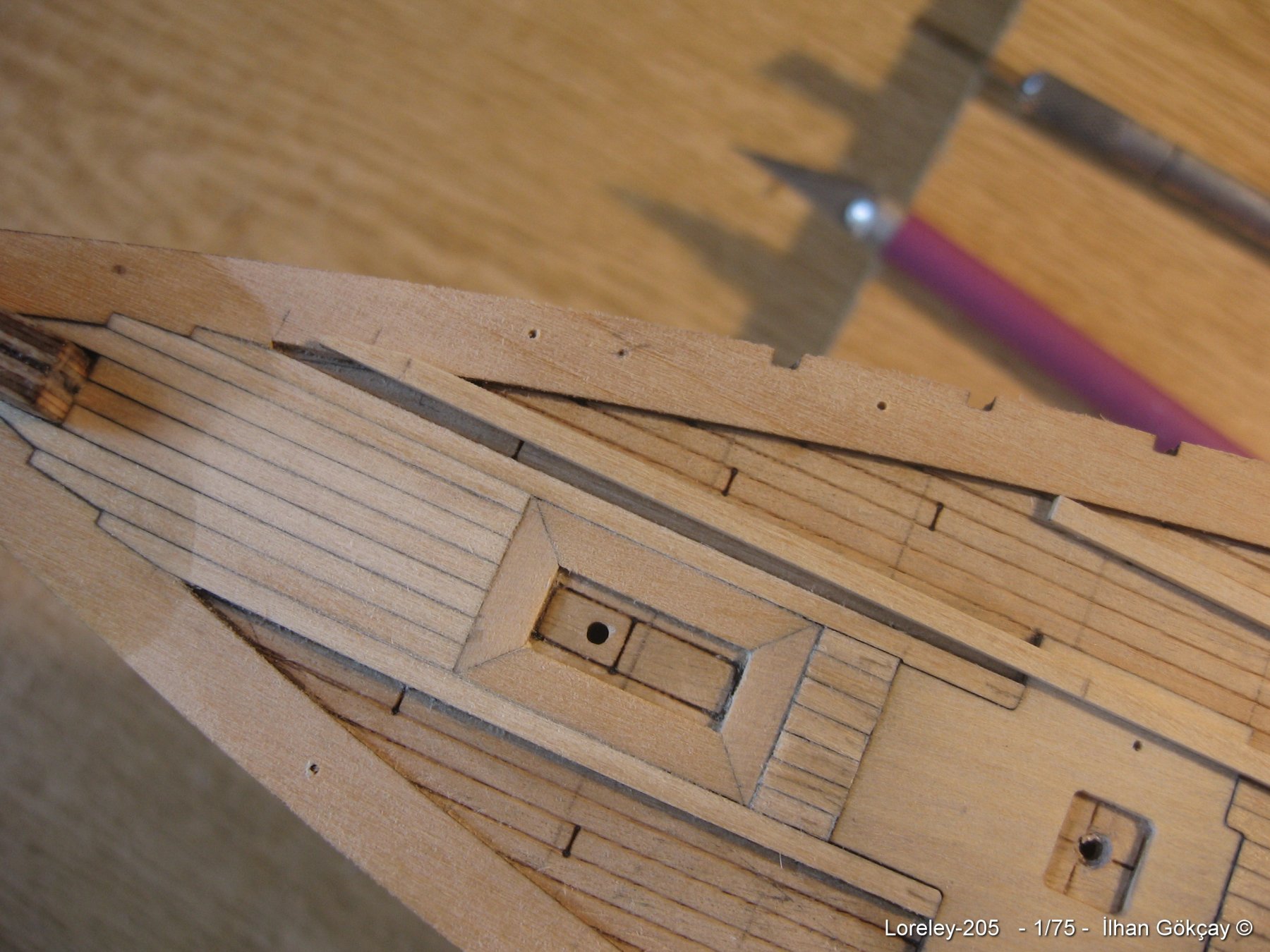
I'm seeking info about a gangway on a deck. The vessel is a passenger ferry paddle steamer.
On the drawings, there is a gangway on the deck crossing midships aft/front the paddleboxes.
I'm trying to find out, how does it look like? Is it a simple second (higher) planking on the wood deck ?
The only cross section view does not tell much but brings up one more questions i.e. "is there a wood planking around the engine room?"
Thanks again in advance for your opinions which are always very helpful.


-
-
-
Still trying to clear up the drawings, my second topic is the gangway on the deck crossing midships aft/front the paddleboxes.
Again the same question arises. How does it look like? Is it a simple second (higher) planking on the wood deck ?
The only cross section view does not tell much but brings up one more questions i.e. "is there a wood planking around the engine room?"
Thanks again in advance for your opinions which are always very helpful.


-
-
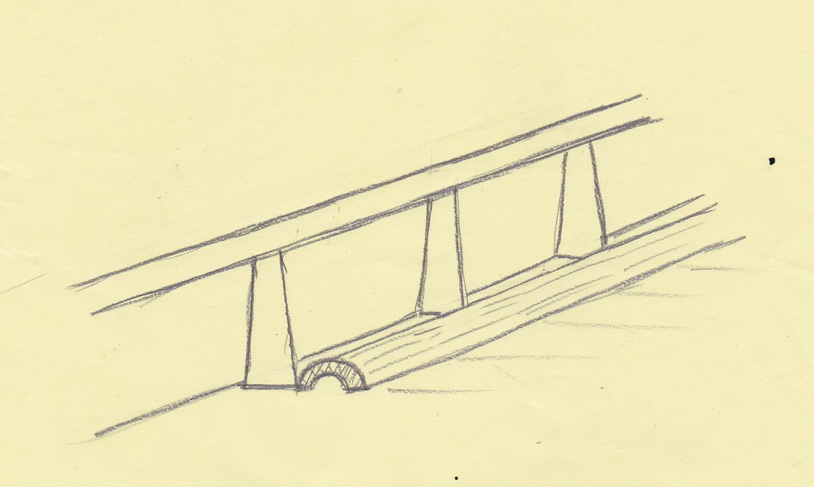
Hey Steve, thanks a lot. Your sketch seems to be the most probable.
By the way I liked your build log.
- mtaylor, Mirabell61 and Canute
-
3
-
-
9 hours ago, kurtvd19 said:
The covers I have observed over the steering chains/rods was a simple cover flush with the deck - as the steering chains were below the decks surface. A simple wood slat assembly that can be lifted out for a wood boat and steel on a metal boats. My experience is strictly with tug and tow boats.
On the drawing side view they probably would not be detailed so you would only have the plan (top) view.
Kurt
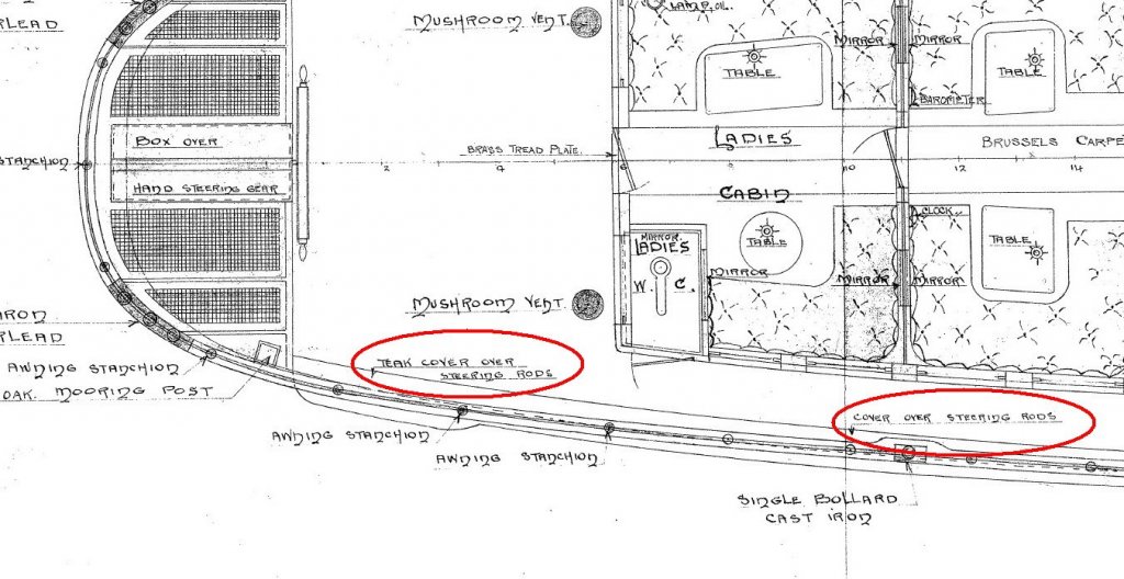
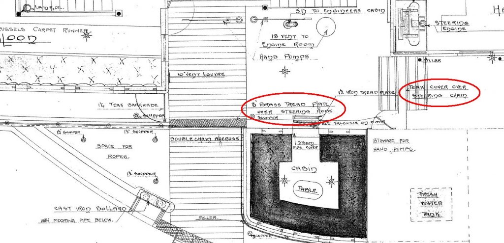
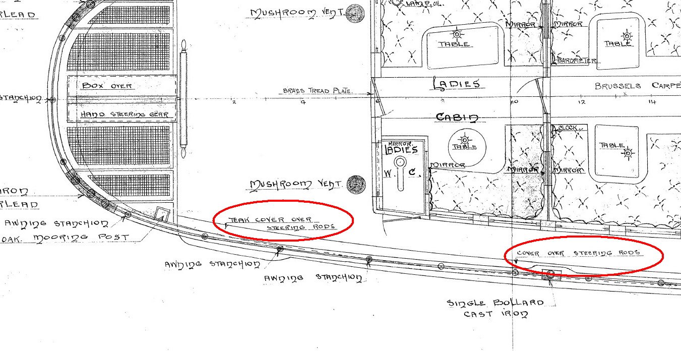
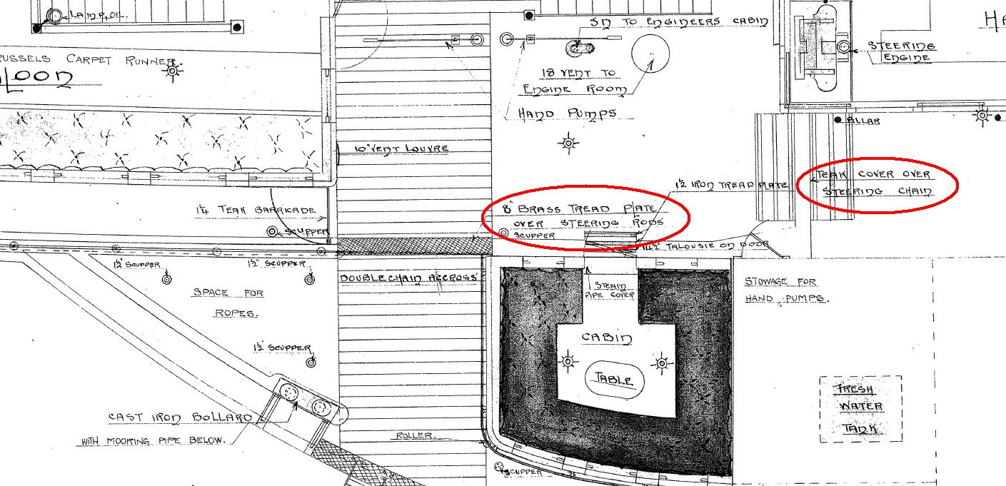
Hey Kurt thanks for the response. That's what I tought at first but on the second photo there are two crossovers over this part. So I assume it's above the deck level. But still not exactly sure about it.
-
9 hours ago, Jim Lad said:
Ilhan,
I haven't been able to find any photos of the cover plates over rod and chain steering, however they were very similar to the cover plates that were placed over steam pipes on deck - just a bit lower as the rods and chains were just above the deck.
The phot below is from Alan Villiers 'Last of the Windships' and shows crew members on the right standing on the steam pipe covers. This might at least give you a starting point.
John
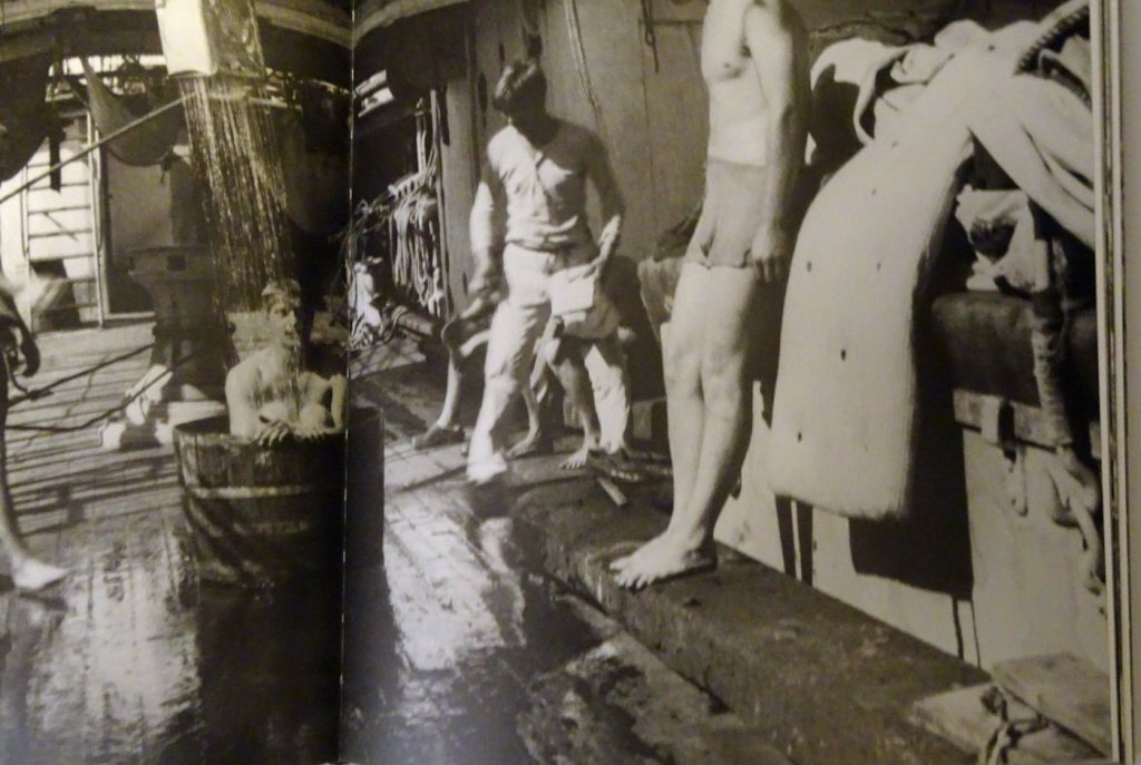
John, thanks a lot for the photo and info. Let me ask you, do you know more about this cover other than this photo.
Is it simple wooden board following the railing? Are the stanchions sitting on top of this board? Or maybe it's in front of the stanchions.
Do you have any idea. I searched many books and drawings, could not find anything. -
Dear friends,
I have some original drawings of a steam paddle ship. There is a point on the drawings which I have diffuculties to visualise as there are not sufficient info. It's steering chain/rod cover.
On the drawing only on the top view its indicated that there is teak cover over steering rod but no other information on other views.
I appreciate any opinion about this, how does it look like.
-
-
Hi Ferit Kutlu, thanks.
That's because I'm building in a room/lounge at home.
Actually I would like to have a small milling machine and a lathe but they are not an absolute must.
-
-
-
-

-1-Gemi-15-Spnsn1_resize.jpg.c972a17000315bfc67f880fb2c74a766.jpg)
-1-Gemi-15-Spnsn2_resize.jpg.2c3a85fac5949cbe4fb827717d985ff1.jpg)


Question about paddle box and sponson of Paddle steamer ferry
in Building, Framing, Planking and plating a ships hull and deck
Posted
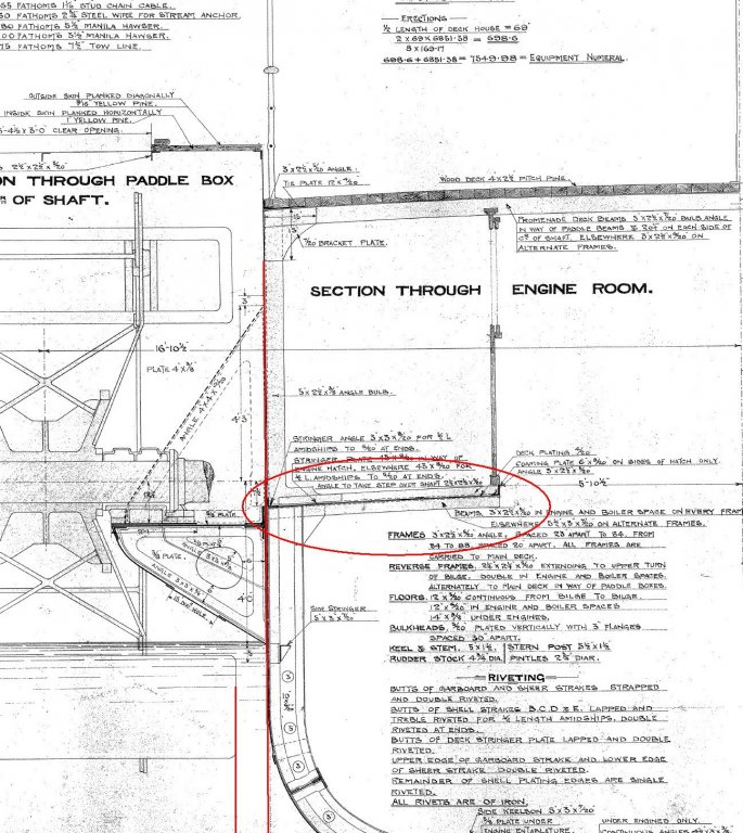
Hey Vince, hello. I would like to ask one more question to you.
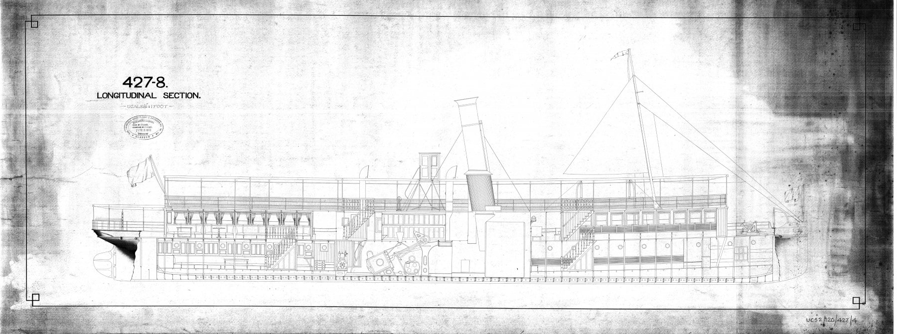
For the outside bearing support of the shaft of the paddle wheel there is only one cross section drawing. On this drawing it's said that there is a hole 15'' Dia. So I assume that this support is box like construction (like prisma) , two triangular side plates and the front is also covered with a plate with a hole in center.
But in such a case it would be always water at the bottom of the box. Is that plausible or how can this construction be? Do you have any idea ?
Ilhan