

Gbmodeler
-
Posts
464 -
Joined
-
Last visited
Content Type
Profiles
Forums
Gallery
Events
Posts posted by Gbmodeler
-
-
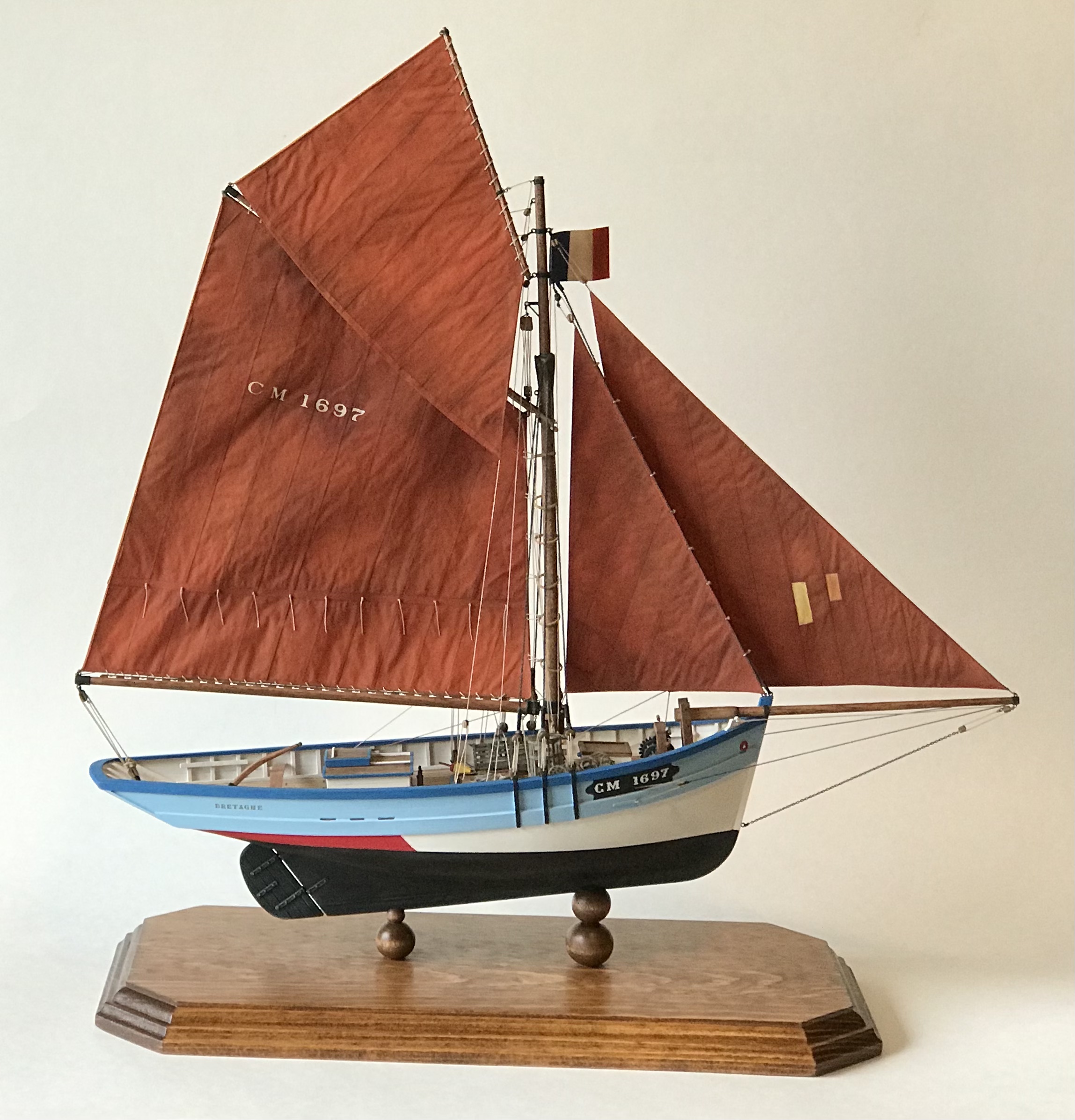
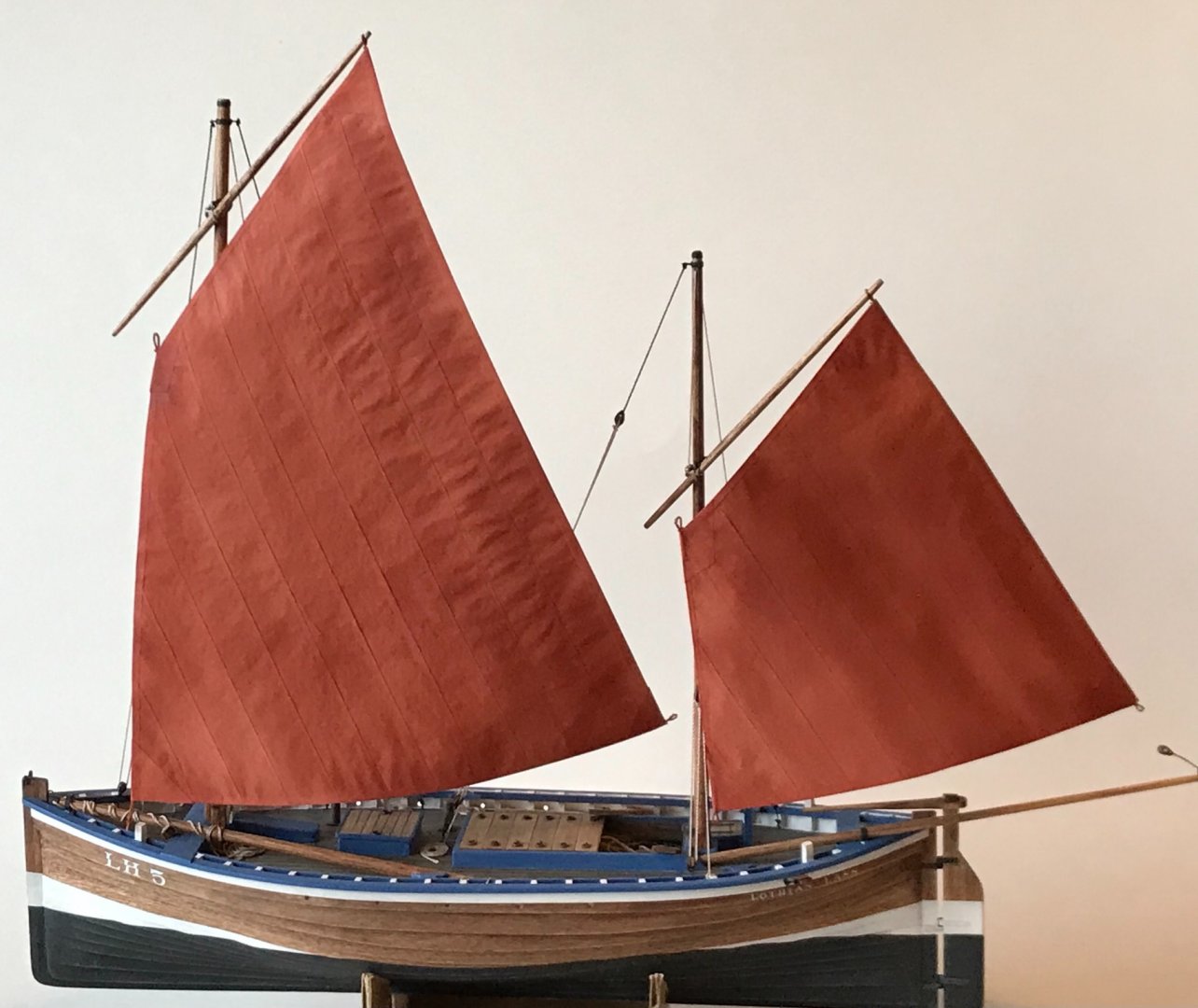
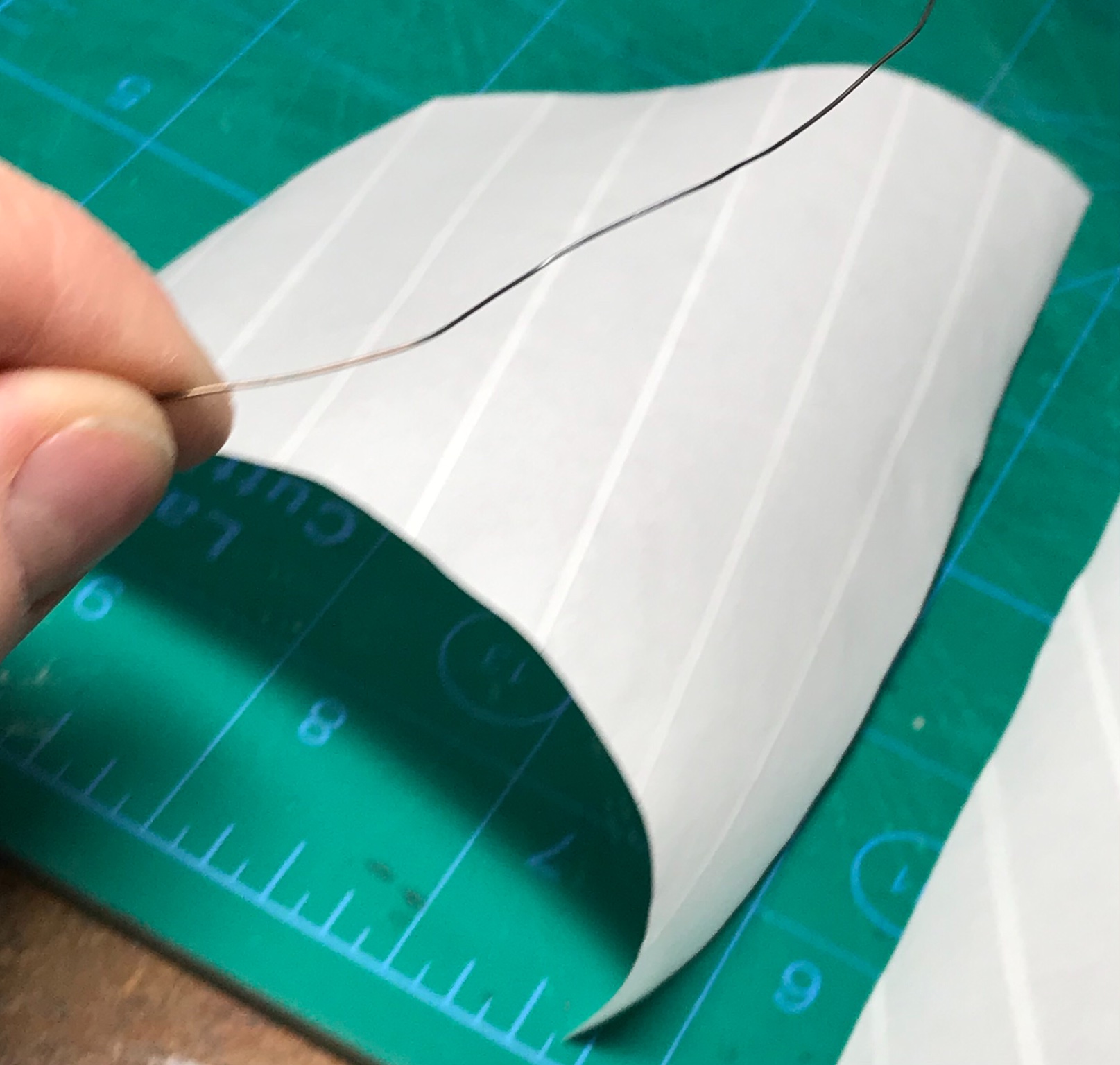
Sail making has begun. As I have shown on previous builds, it starts with cutting 15mm wide strips of graphic marker paper and gluing them together with diluted PA glue. The overlapping seams are 1mm wide.
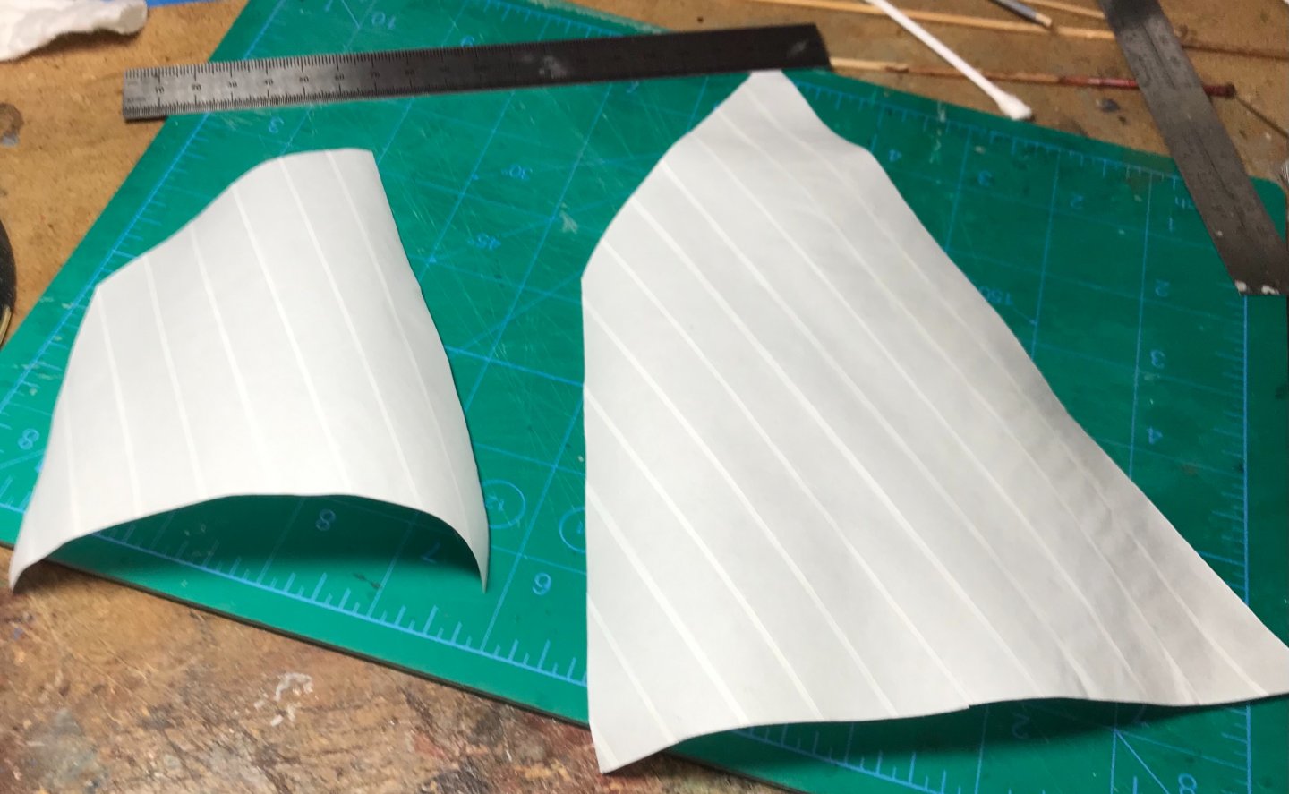
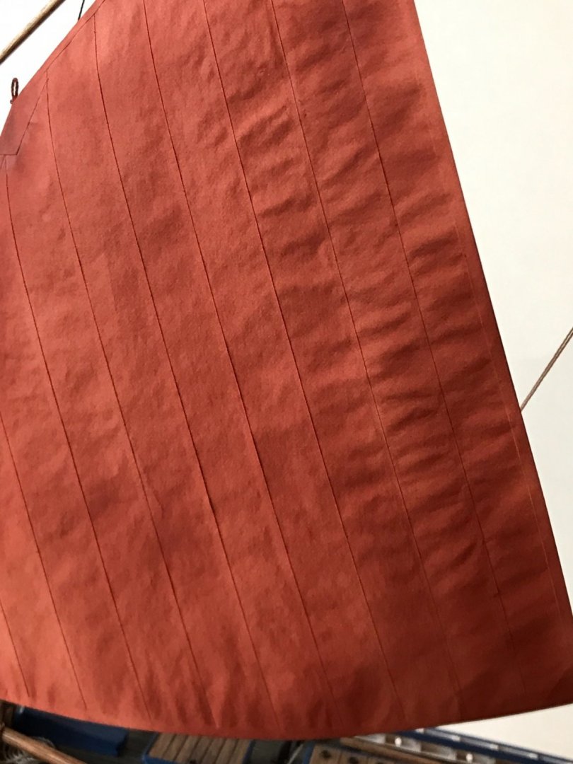
I embed wire under edge-trim pieces along the leech (sail's back edge) and the foot (sail bottom edge). The wire can be bent later, to make it appear the sails are filled with wind.
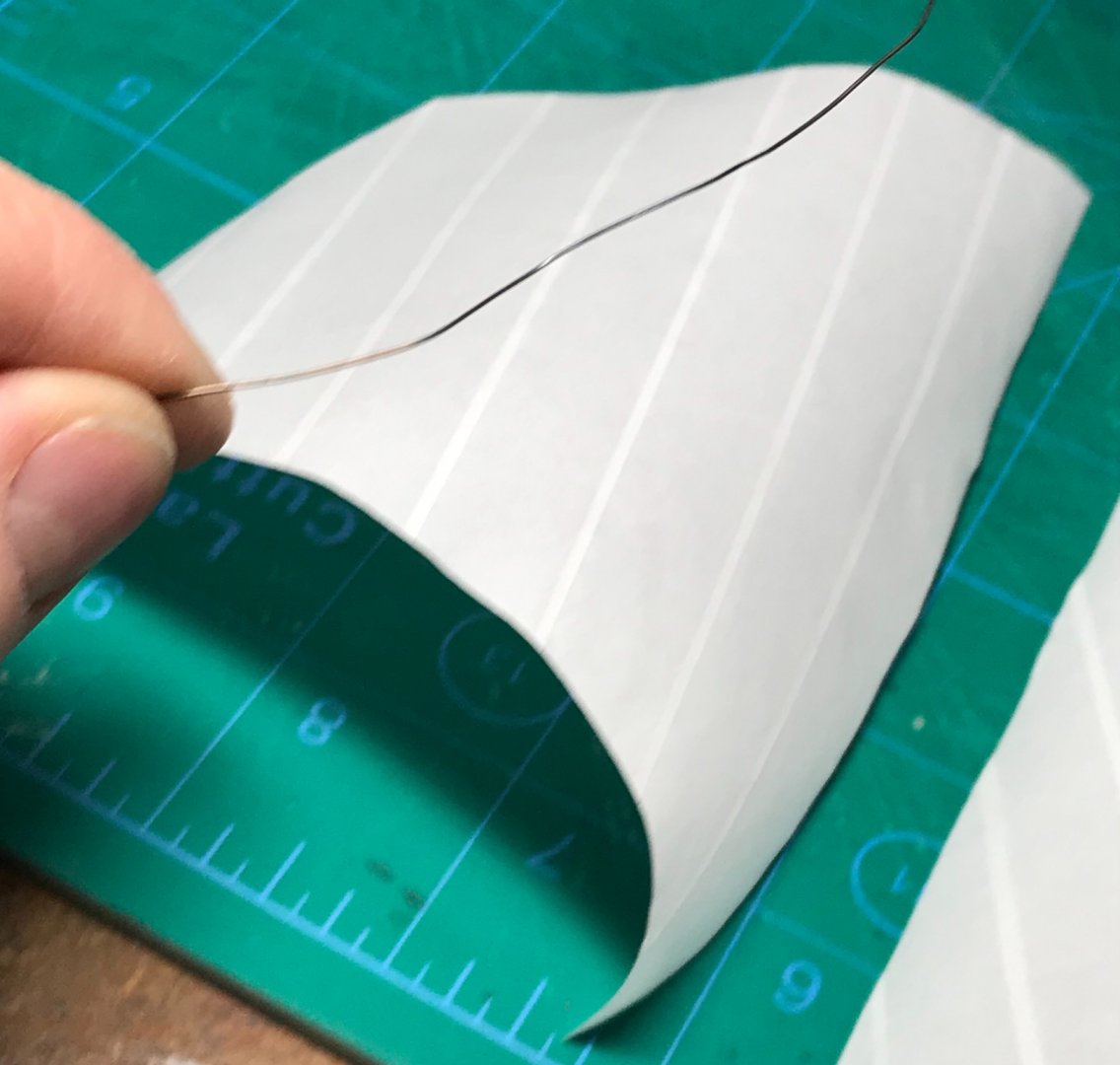
I also embed loops of rope at the corners for clews. Here the fit is being tested...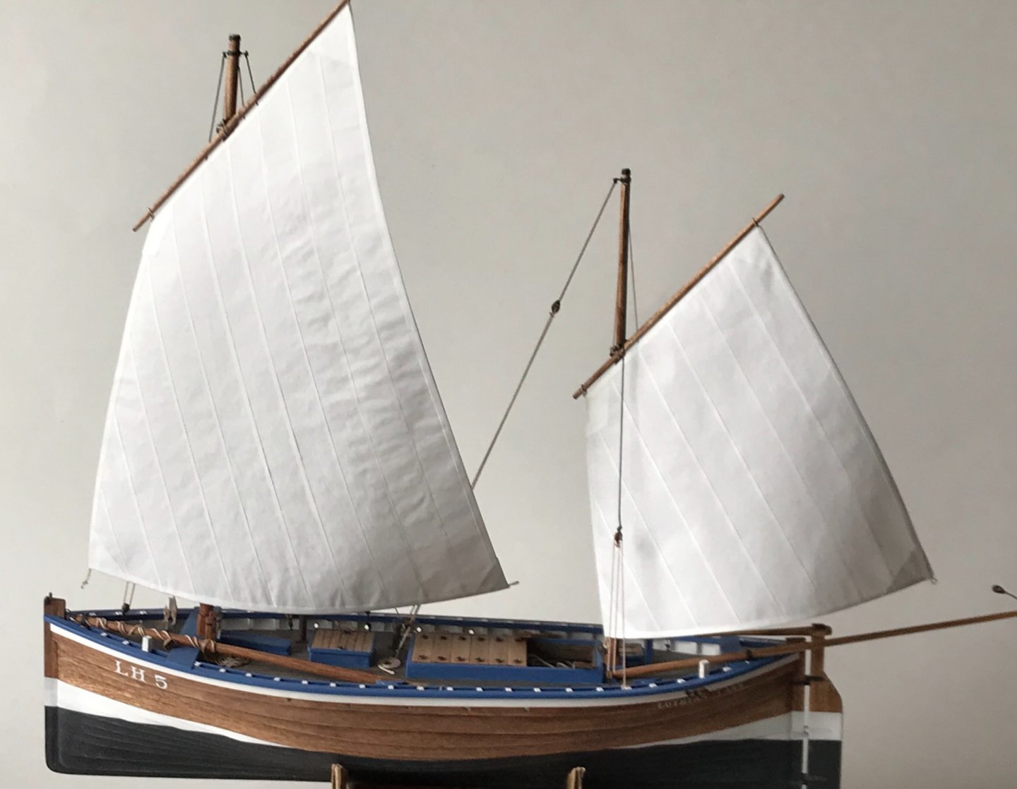
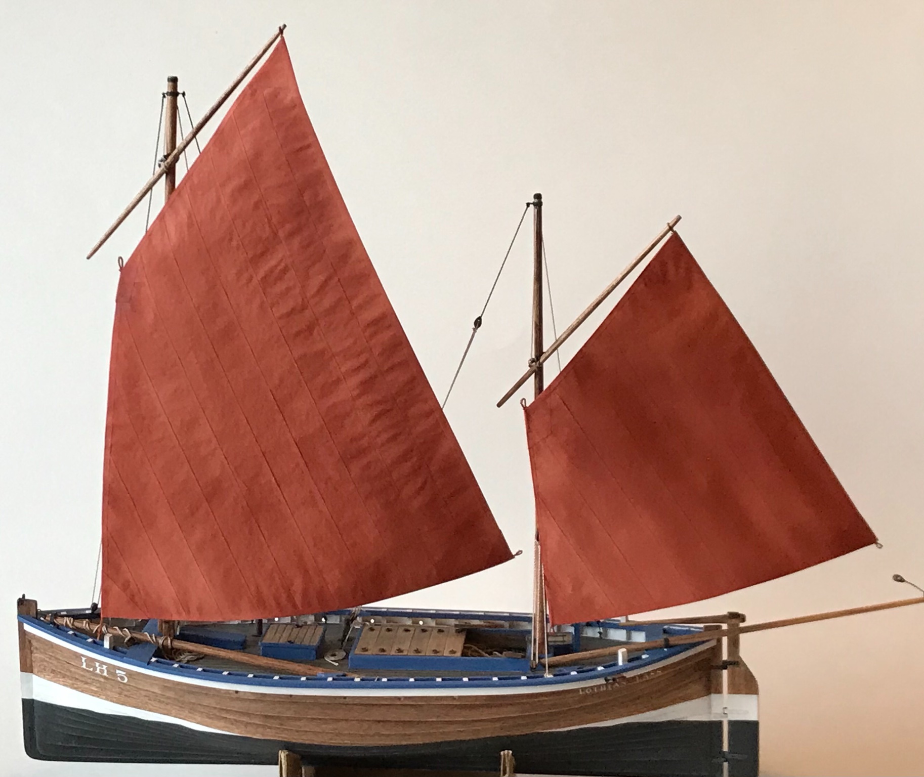
Next, the sails are colored, if needed. In this case a rusty mix of Tamiya acrylic model paint was airbrushed over the sails...
- Wintergreen, Moab, wefalck and 6 others
-
 9
9
-
10 hours ago, Chuck said:
Look here for a ton of tutorials on rope making and ropewalks
https://modelshipworld.com/forum/82-discussions-about-rope-making/
and here
https://modelshipworld.com/forum/83-rope-materials-and-parts-resources/
and here
https://modelshipworld.com/forum/81-ropewalk-plansdownloads/
Thanks Chuck! Loads of info out there!
-
10 hours ago, wefalck said:
There are lots of examples, just search for 'ropewalk'. It's not difficult and a ropewalk can be improvised easily - the guys of old also used 'home-spun' ropewalks. Properly done 'rope' is much tighter and better 'defined'. Particularly in the larger scale you are working in, this is quite visible. I think it would add a lot of extra value to your nice boats.
Thanks for the hints Wefalck! You always have very constructive comments.
-
1 hour ago, wefalck said:
Same question as to the lettering ...
Have you thought about making your own 'rope' ? Would add a tad more to the pretty good realism already.
I see some folks make their own rope but I have not yet considered it. It does look better! Are there any tutorials anywhere???
-
2 hours ago, bruce d said:
Very nice work, it's got that 'working boat' feel all over it.
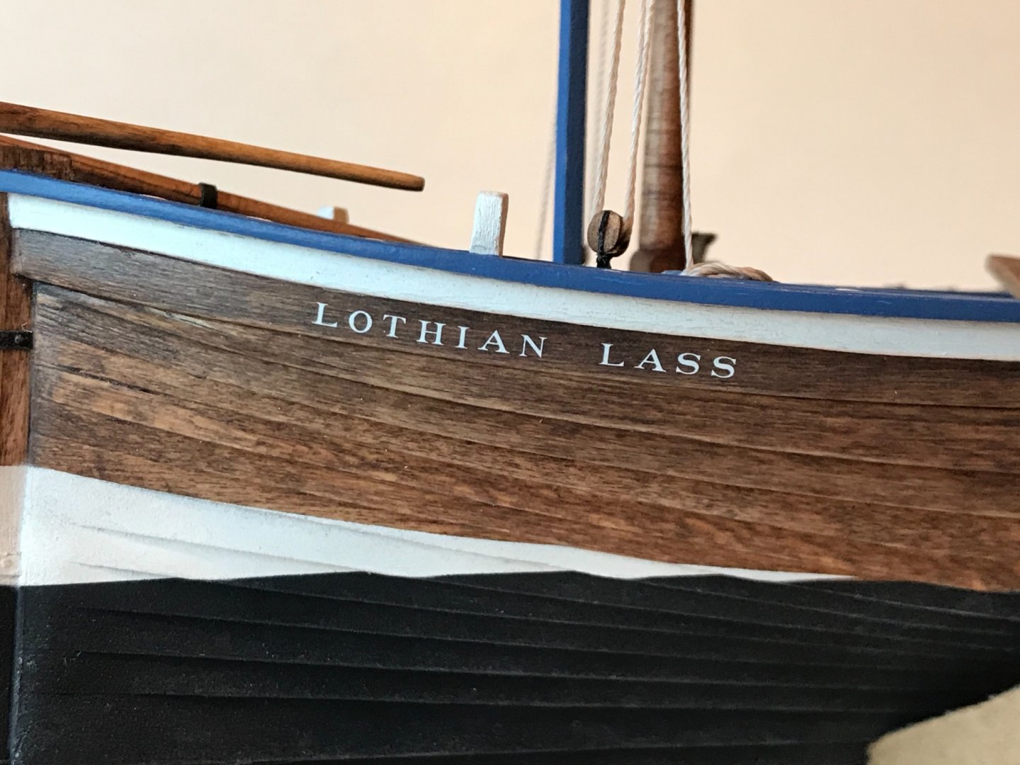
Good job on the lettering, can I ask how you did it?
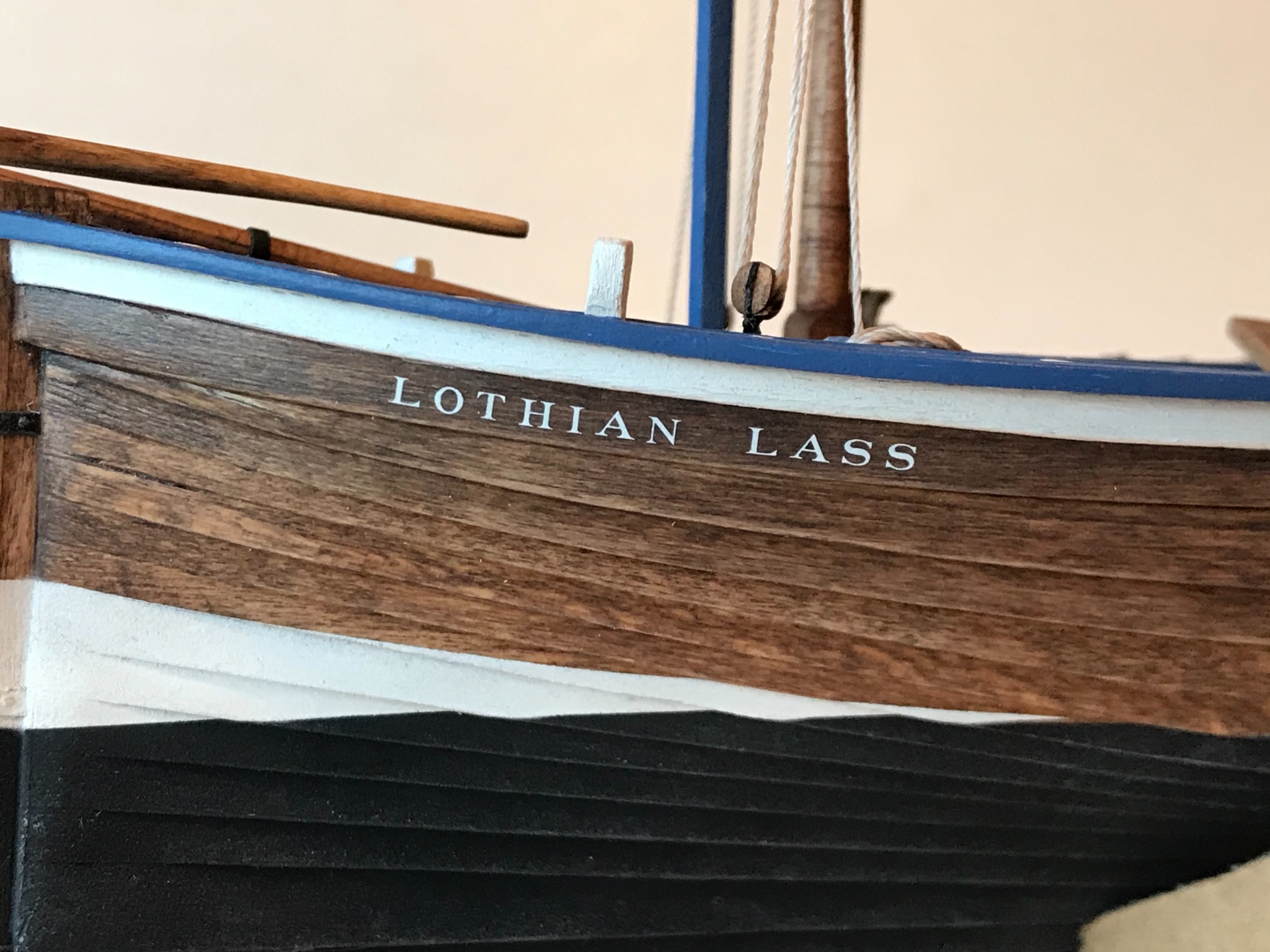
Thanks Bruce D! The lettering is made from water-slide decals from Microscale. They are individual letters and numbers made for model railroads, and come in various sizes, fonts, and colors.
-
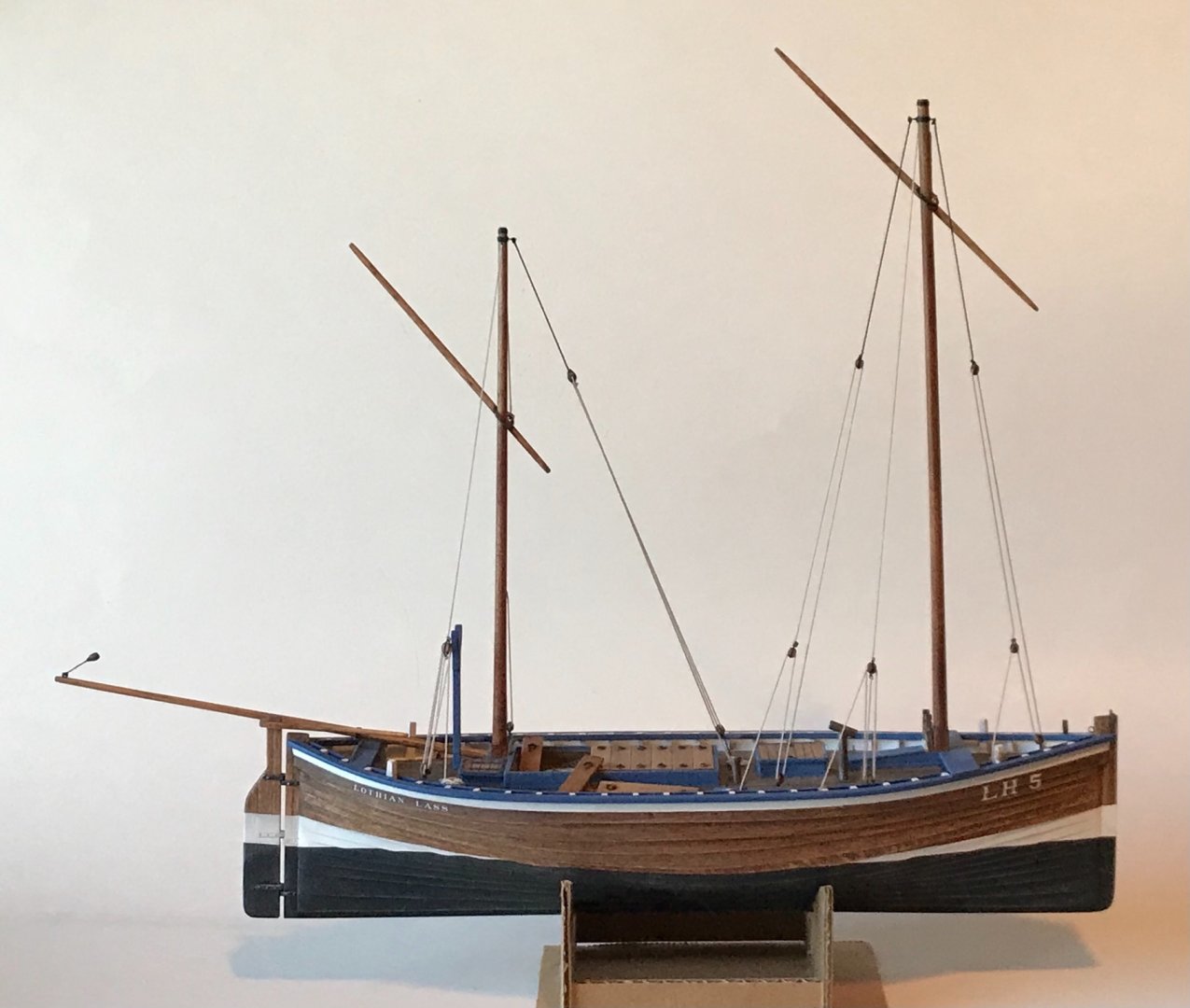
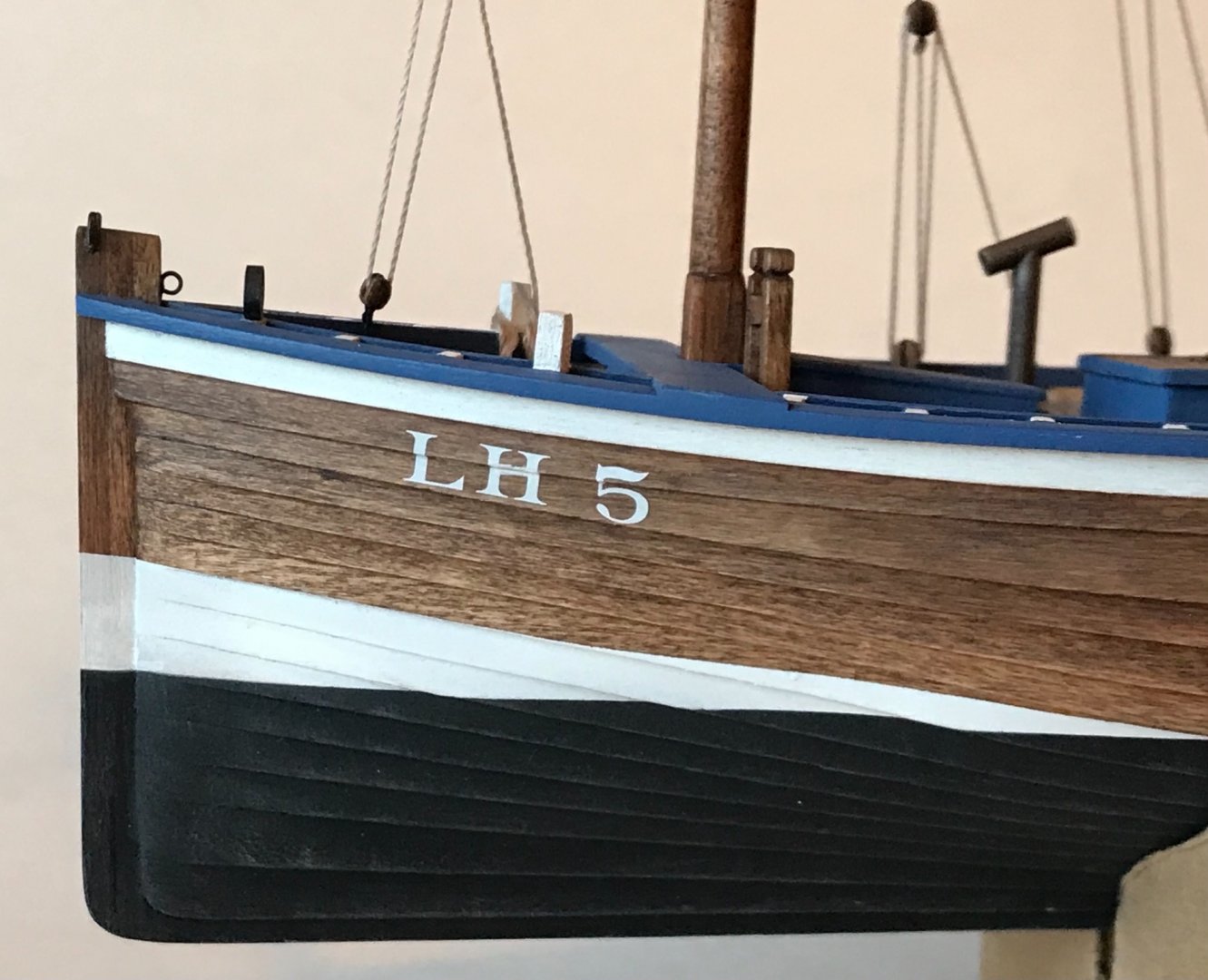
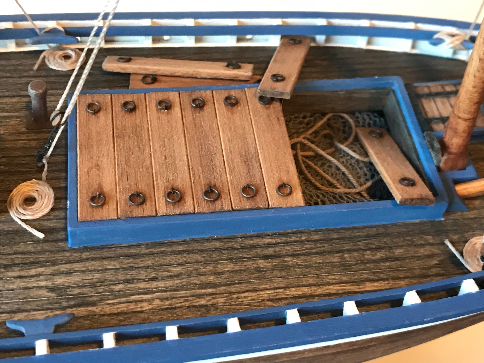
The masts are stepped and a lot of the rigging is done. Started adding details like mast wedges, rope coils, fish nets in the hold, and hatches askew. Also applied the registration number (LH 5) for Leith (Edinburgh), Scotland and dubbed her the "Lothian Lass." I have ancestors from that area, east of Edinburgh...


-
14 hours ago, wefalck said:
It comes out nicely. One can imagine that these were quite sturdy and powerful boats under sail ...
Yes, everything I have read suggests they were heavily built and tough!
-
-
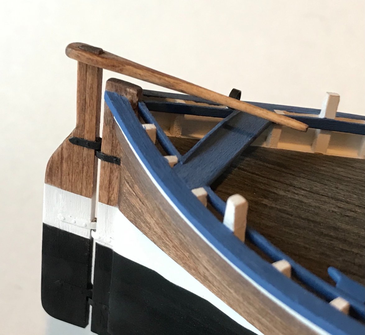
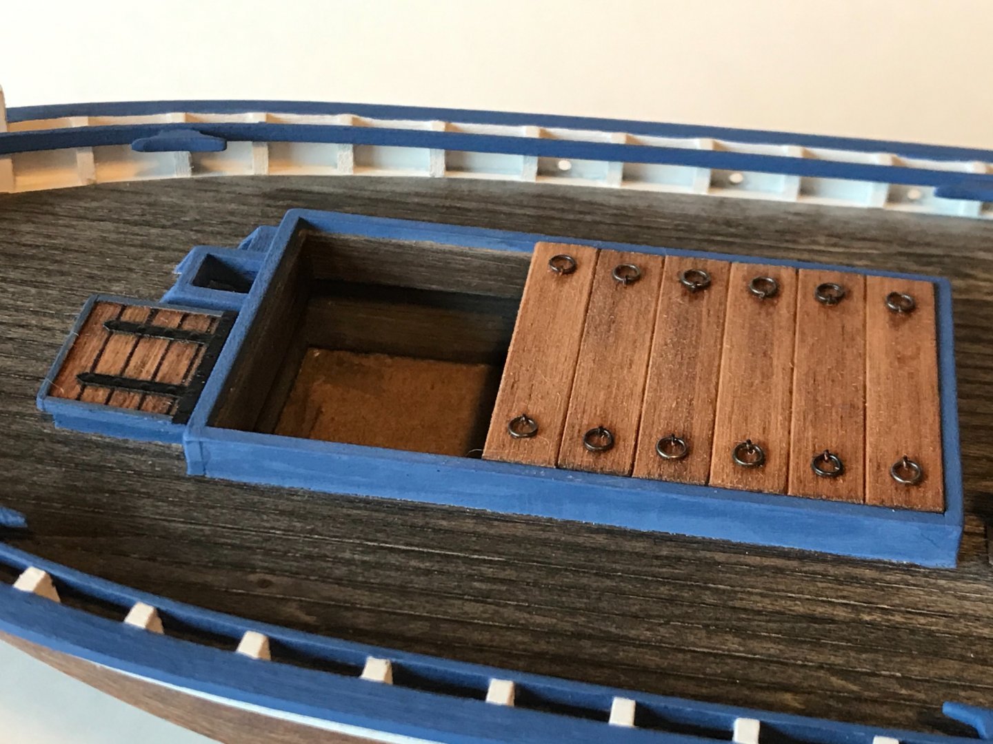
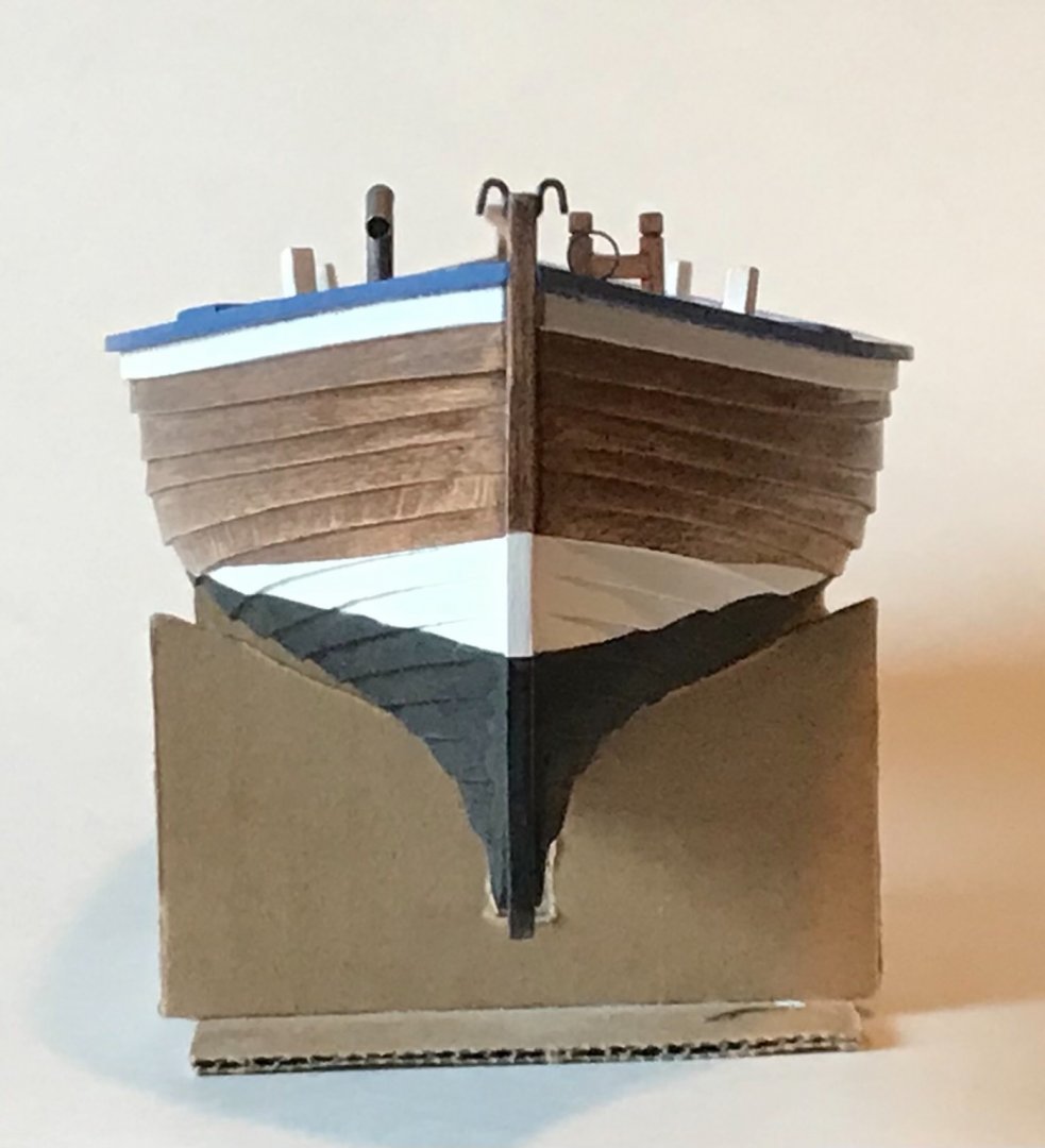
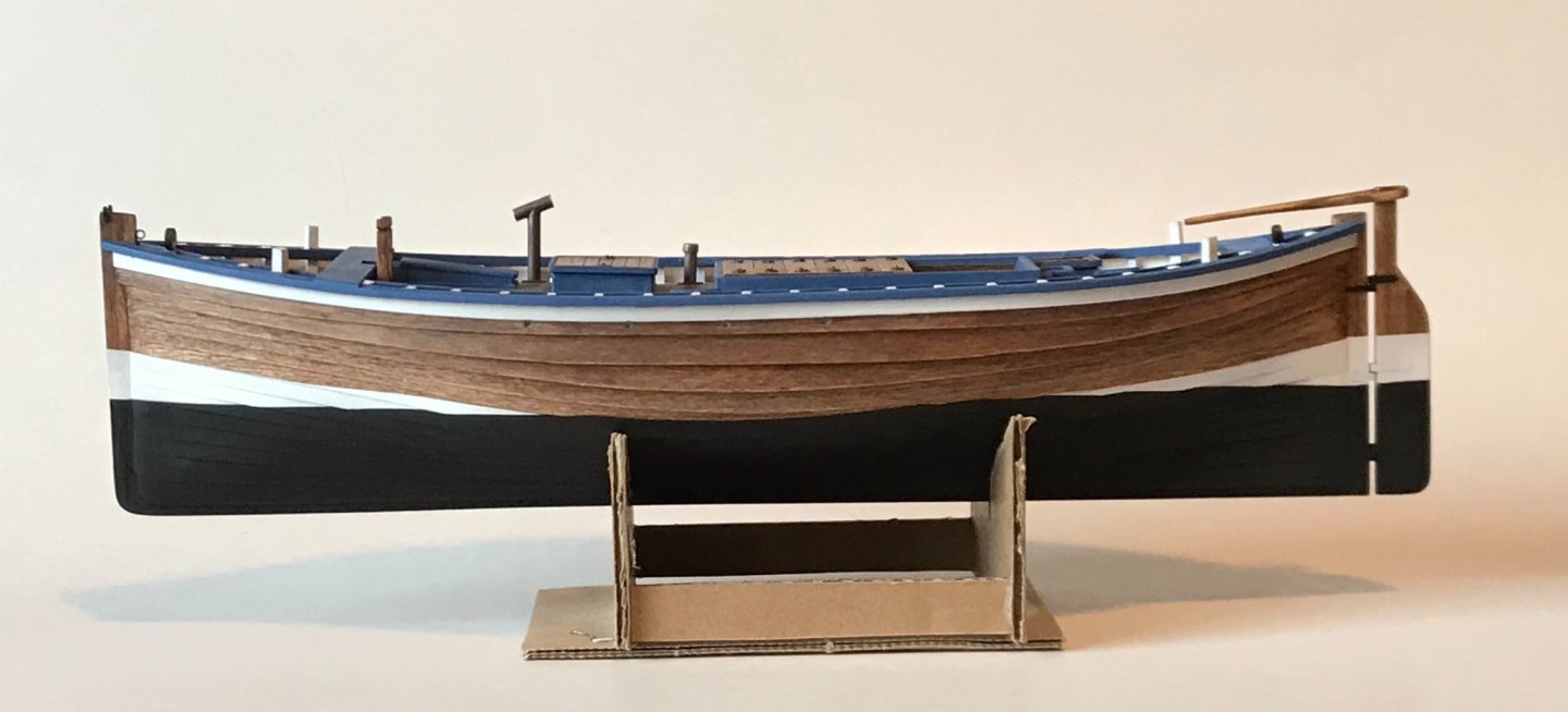
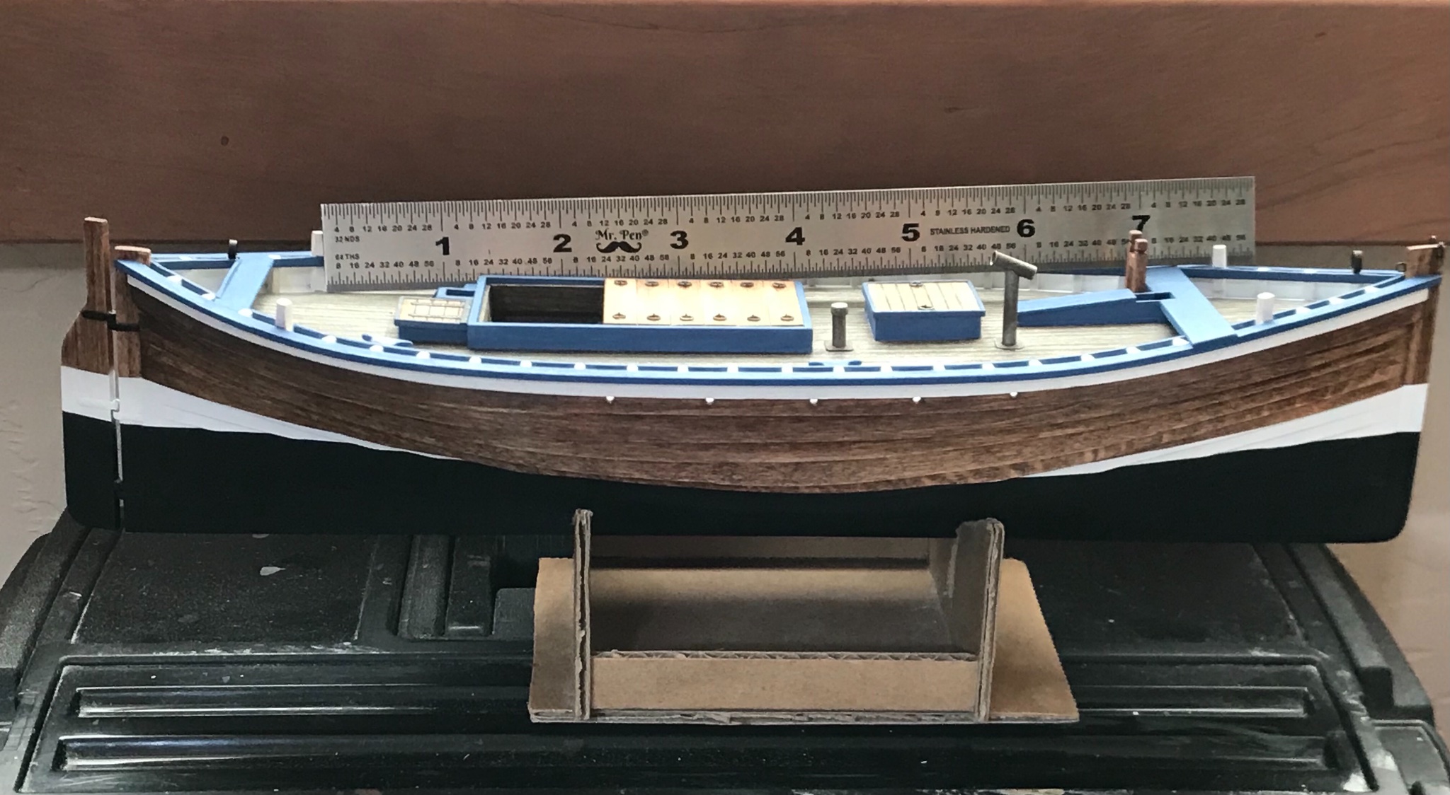
Over the last few days I have been able to work on a lot of little fiddley-bits (built the rudder and tiller, finished the hatch covers, installed rings, bitts and/or chocks for the bowsprit and jib, added a stove pipe to the fore room, and masked and painted the lower hull). I also have been doing further work on the masts an spars. Rigging should be starting soon!
The rudder works, using brass tube and copper wire for gudgeons and pintles. The hinges are heavy paper with three-dimensional resin decals for rivets.
Hatch handles are copper wire...
Styrene plastic tube for the bilge pipe and smoke stack...
- wefalck, ccoyle, Roger Pellett and 11 others
-
14
-
-
-
1 hour ago, Wintergreen said:
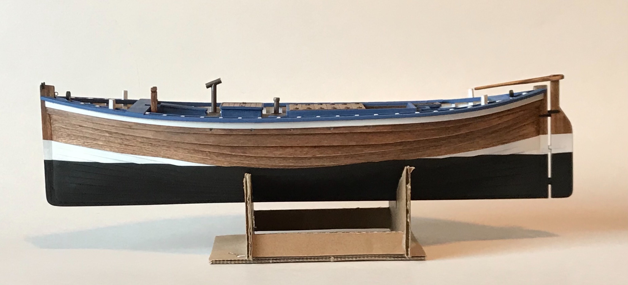
The last picture is really good. Just need some photoshopping on the stand 😉
What kind (type and nuance) of paint is that blue btw?
I just bought myself a set of artist acrylic paint since I've read here on MSW that others use that also.
Keep it up!
Thanks Wintergreen! The blue paint is an unmeasured mixture of Tamiya flat blue and flat white acrylic model paint. Trying to look like the colors in the Scottish flag (Cross of St. Andrew). What's wrong with the "highly-engineered" stand?😇
- mtaylor, Roger Pellett, Wintergreen and 1 other
-
3
-
 1
1
-
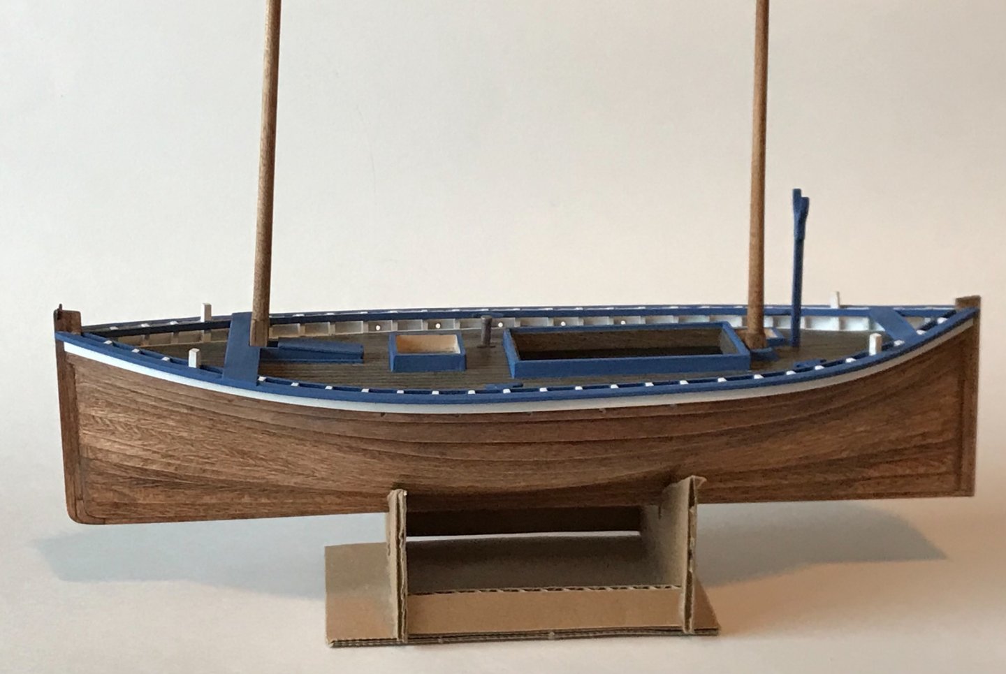
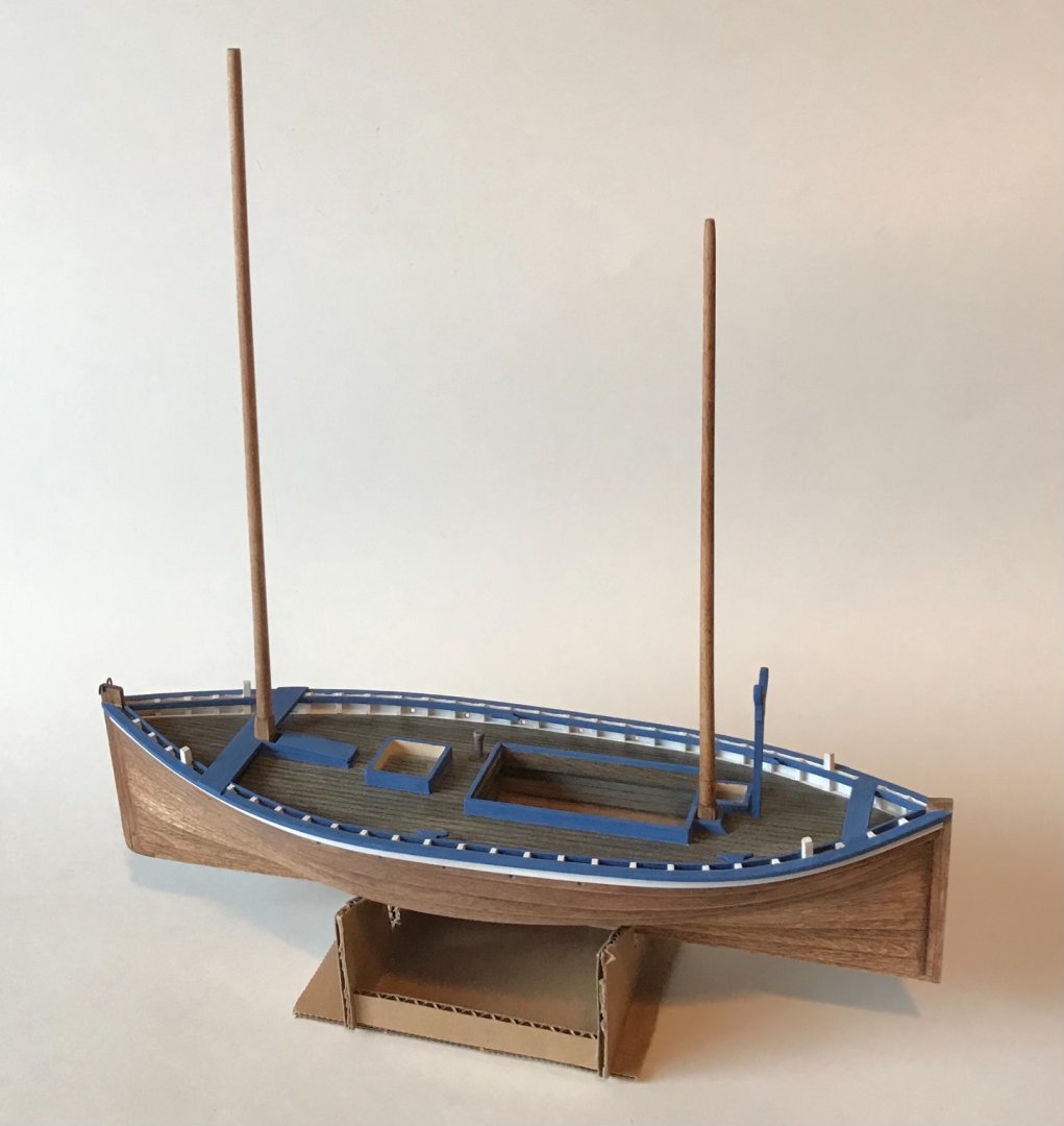
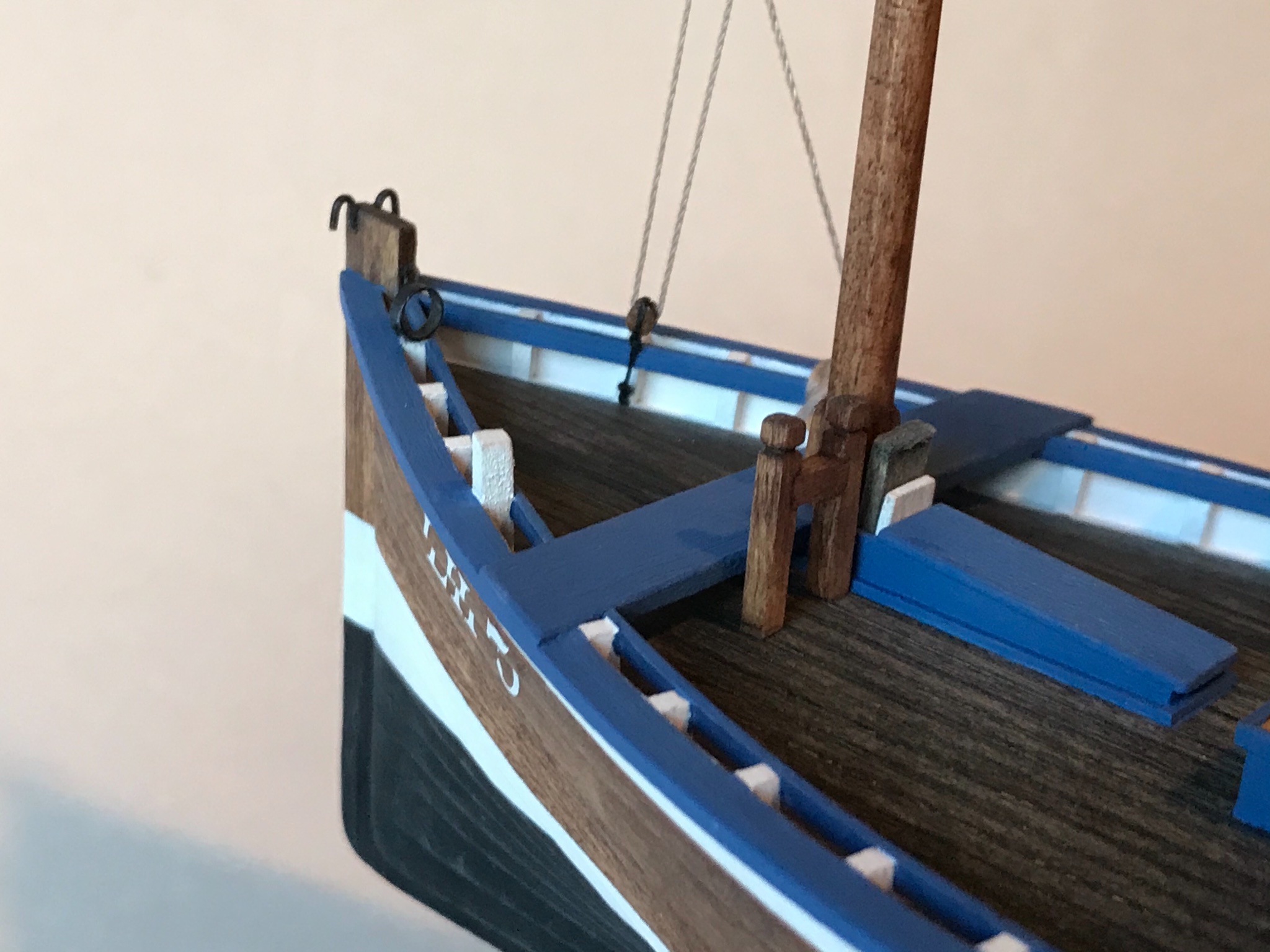
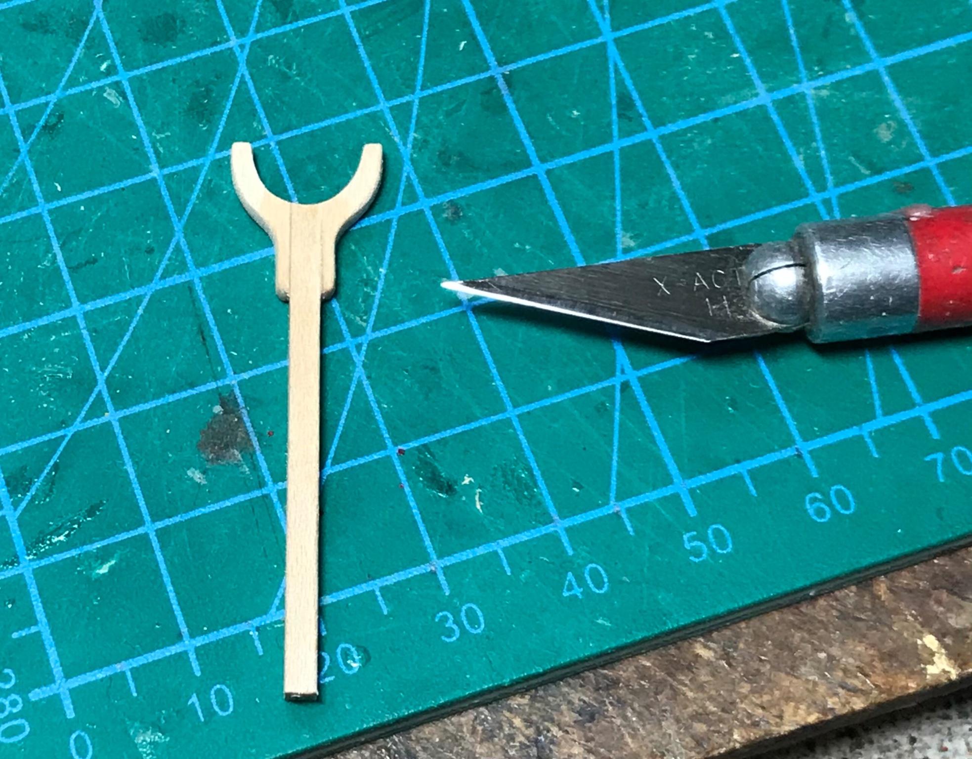
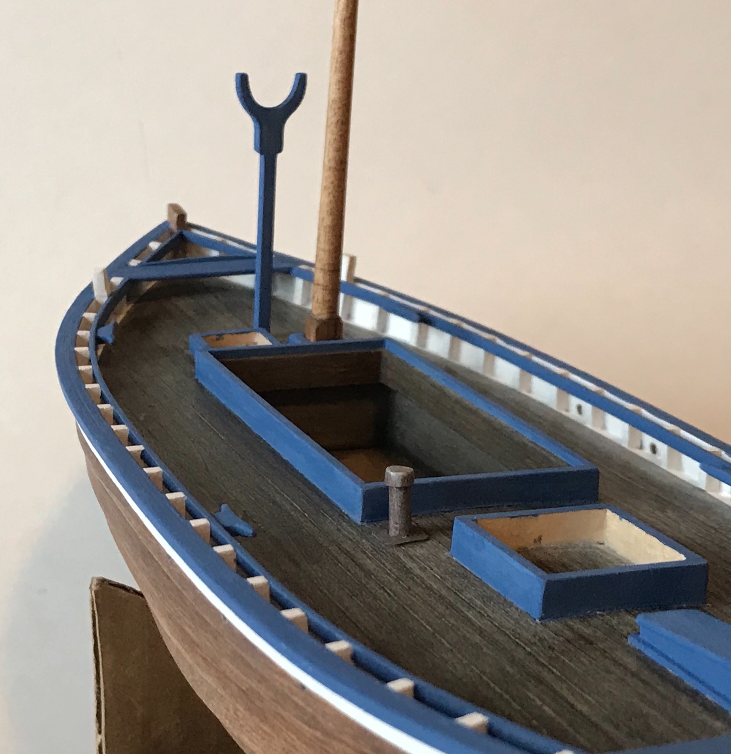
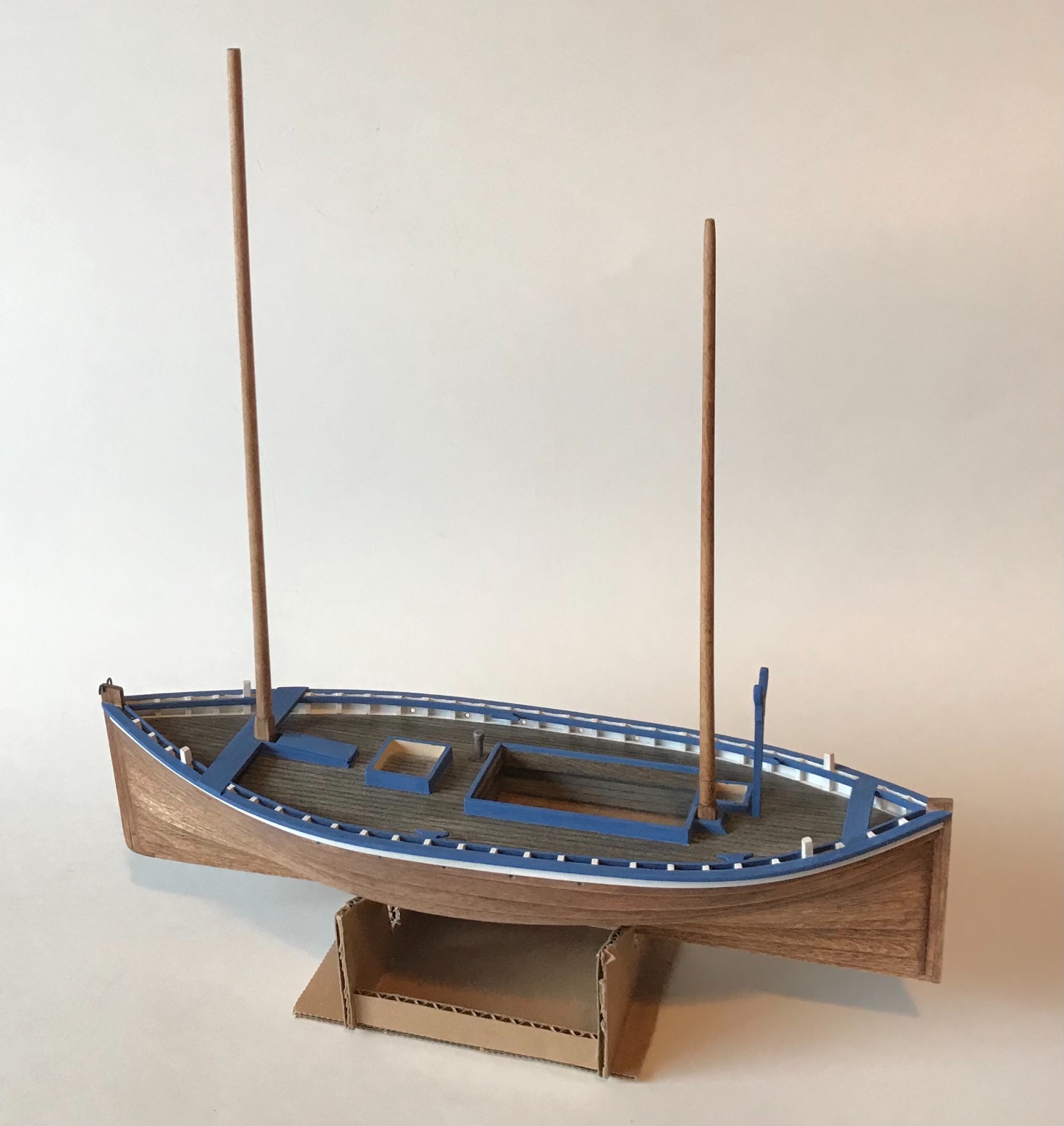
Today a "crutch" was carved and the masts were assembled (but not yet glued in place). The fore mast is lowered down into the crutch during drifting operations and, judging from historical photos, when the boats are in port. The masts are dowels. I tapered them by locking them in an electric drill and sanding as they spun. The masts needed square bases, so those were added after the masts were tapered. I glued strips of wood around the base of the masts with CA glue, and then sanded them square. Lastly, most Fifies had hooks on the stem post where the tack of the fore lug sail was attached.


-
-
1 hour ago, wefalck said:
So the fore-mast sits in a kind of tabernacle ? How is it going to be locked against the 'baulk' ?
Did you pin the cleats to the bearer ?
Nice job overall !
Thanks Wefalck! From reading "Sailing Drifters" by Edgar March, the fore mast was stepped into a tabernacle under the deck mounted to the floors. It was kept upright by a heavy chock and wedges aft of the mast (which I have not yet built).
Yes, the cleats are pinned with copper wire that runs through the bearer and into the frame.
- Keith Black, mtaylor and wefalck
-
3
-
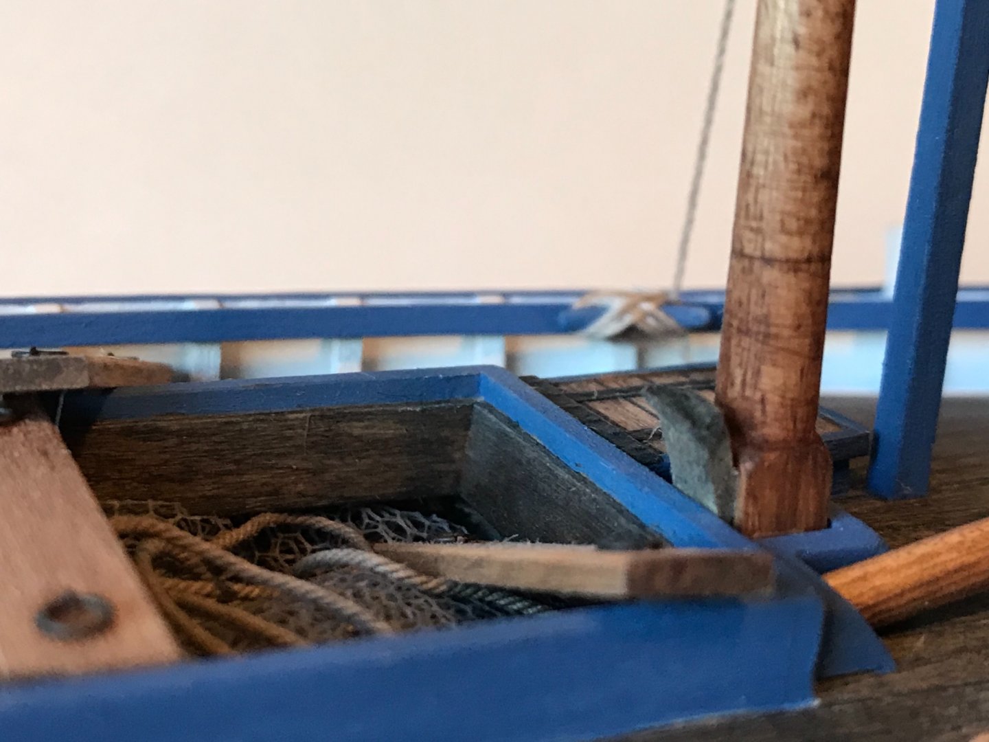
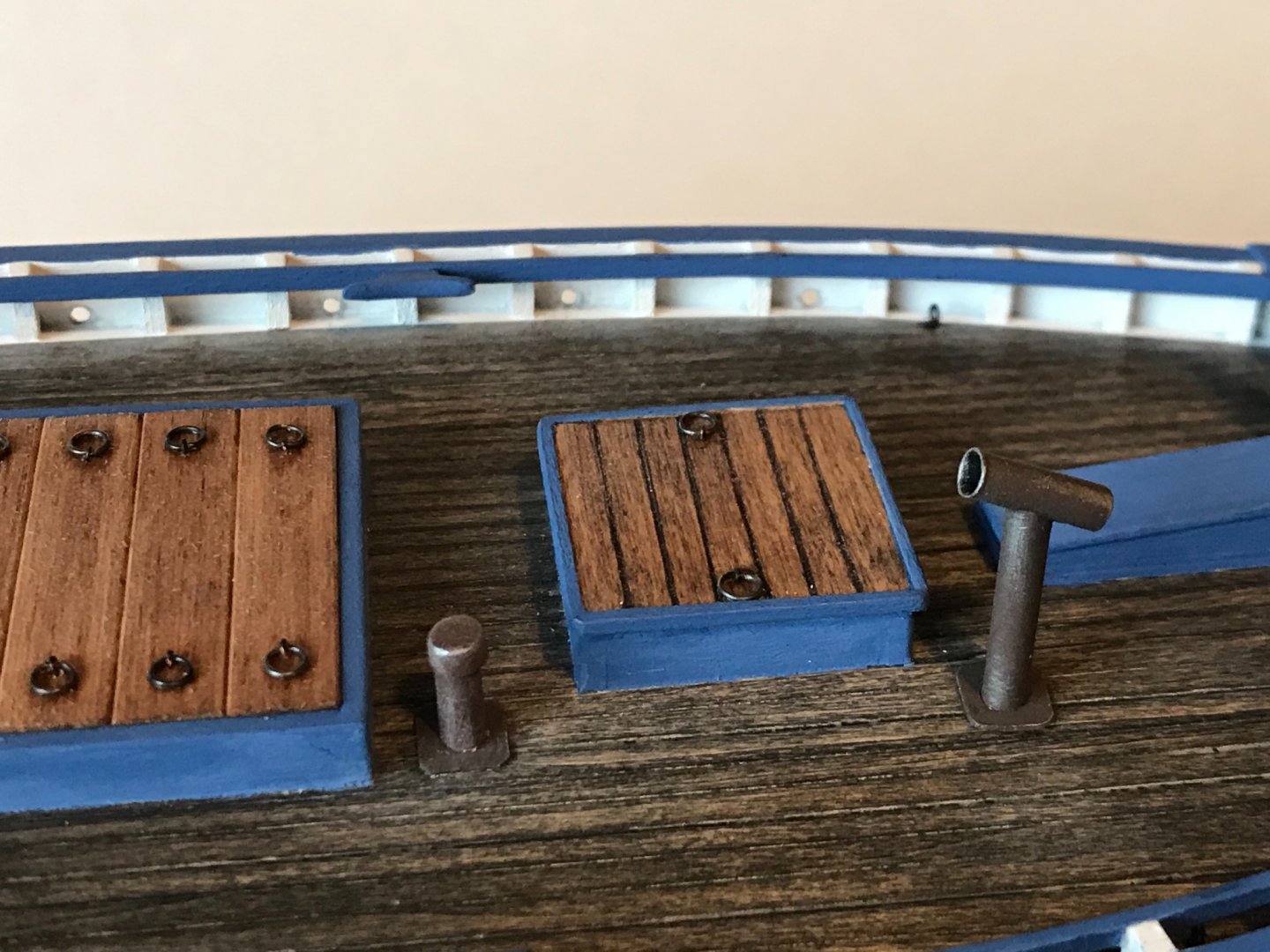
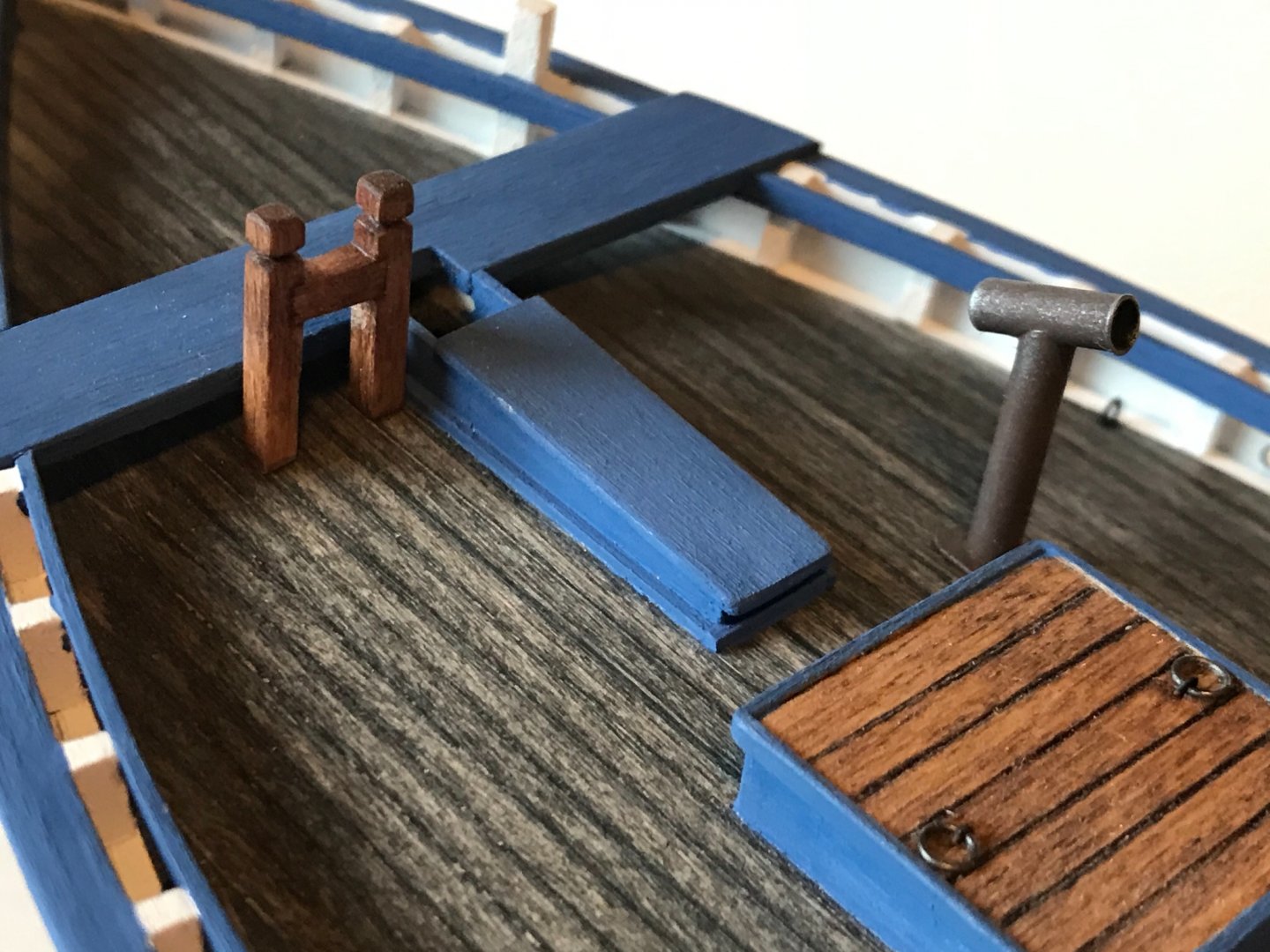
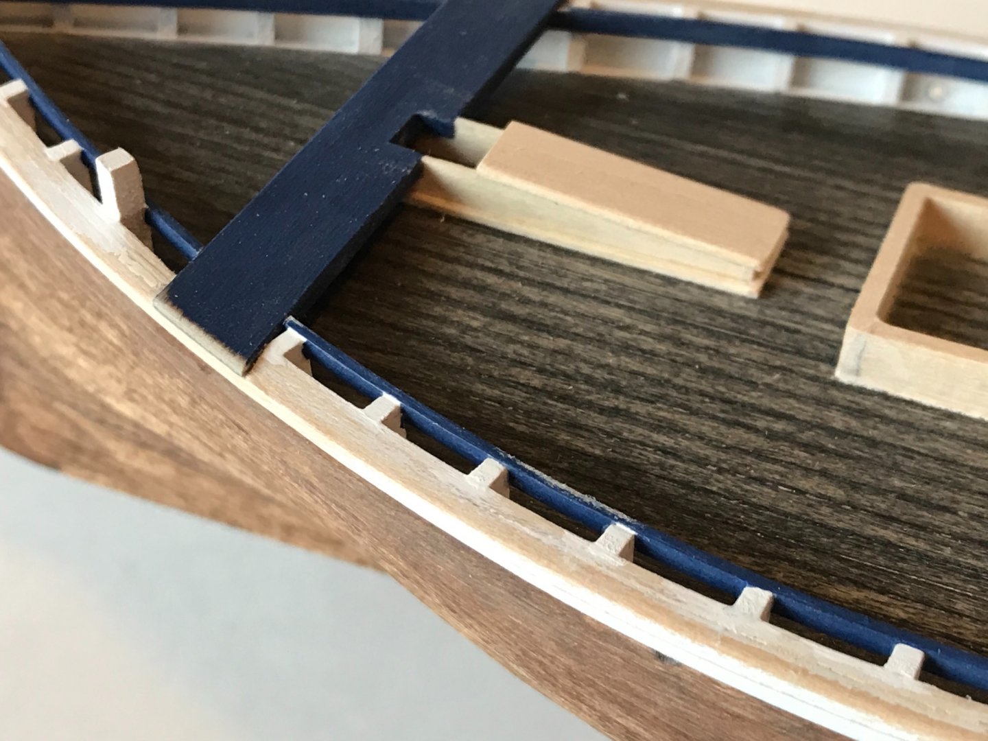
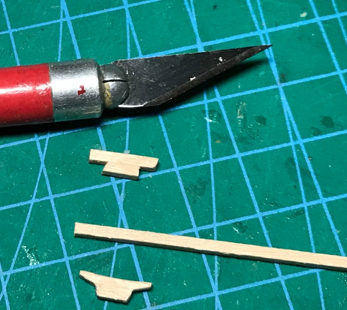
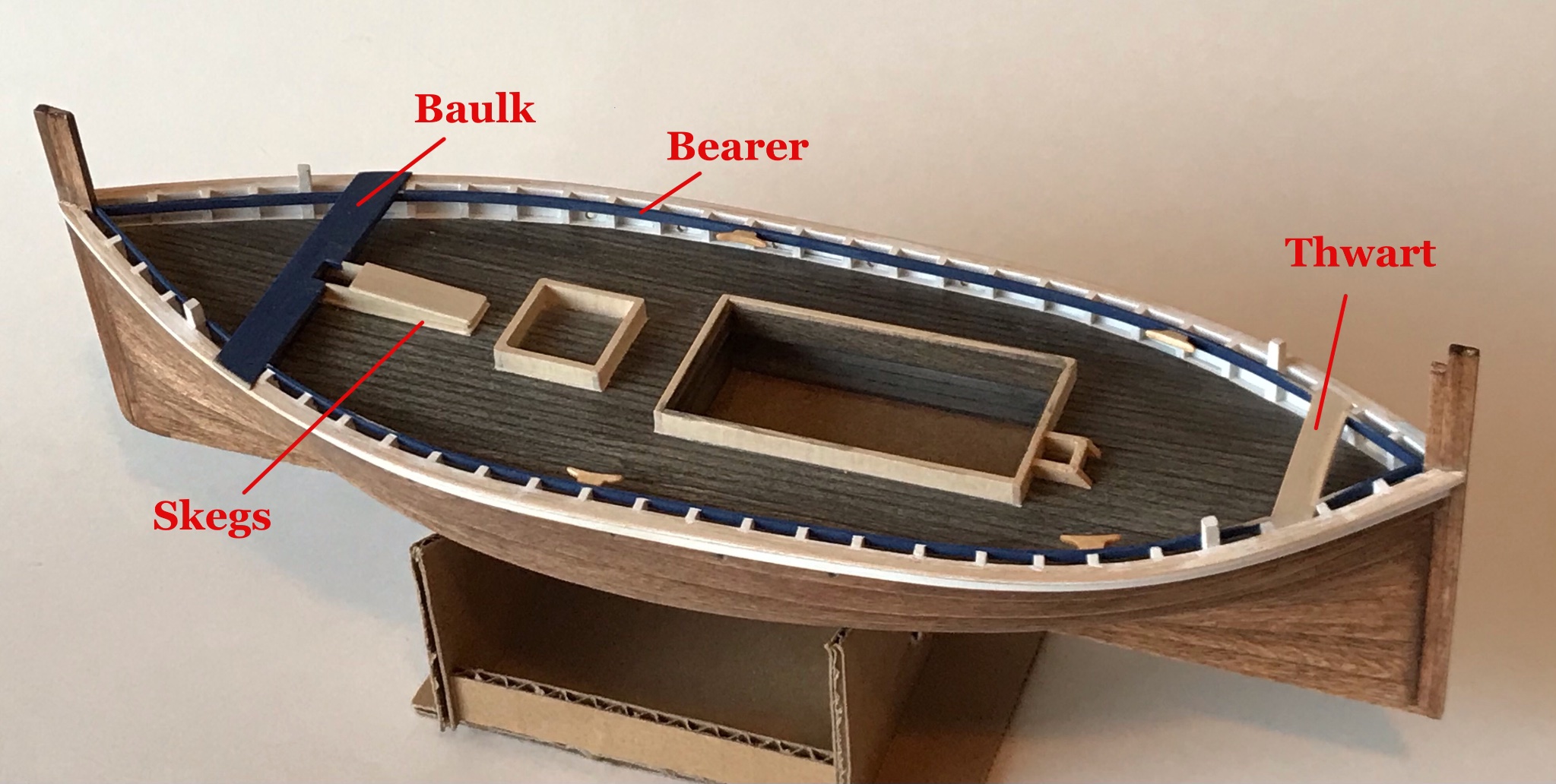
Work continues on the deck fittings. The first major item after the hatch coamings was the "baulk." On Fifies and other Scottish luggers, the baulk was a heavy transverse beam that helped support the fore mast.
Just aft of the foremast was a slot in the deck called the "skegs." The foremast could be lowered backwards into the skegs (not to be confused with the term skeg, which is a projection on the keel). The fore mast was lowered after the nets were "shot" to minimize rolling as the boat (and nets) quietly drifted toward the wily herring 🤫. When lowered, the mast was often supported by a Y-shaped "crutch" (yet to be installed) mounted toward the stern of the boat.
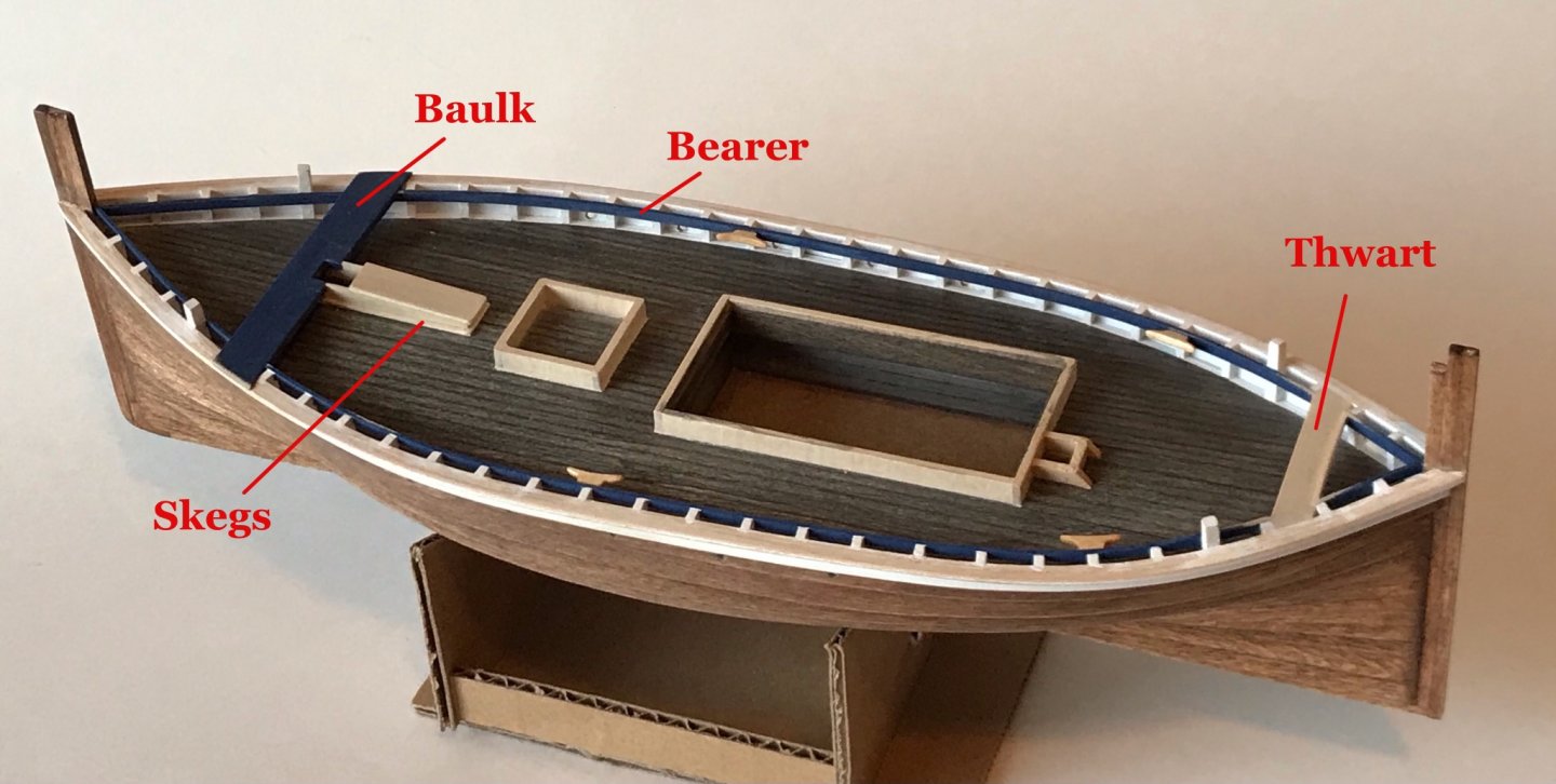
A "thwart" (traverse seat) was added aft.
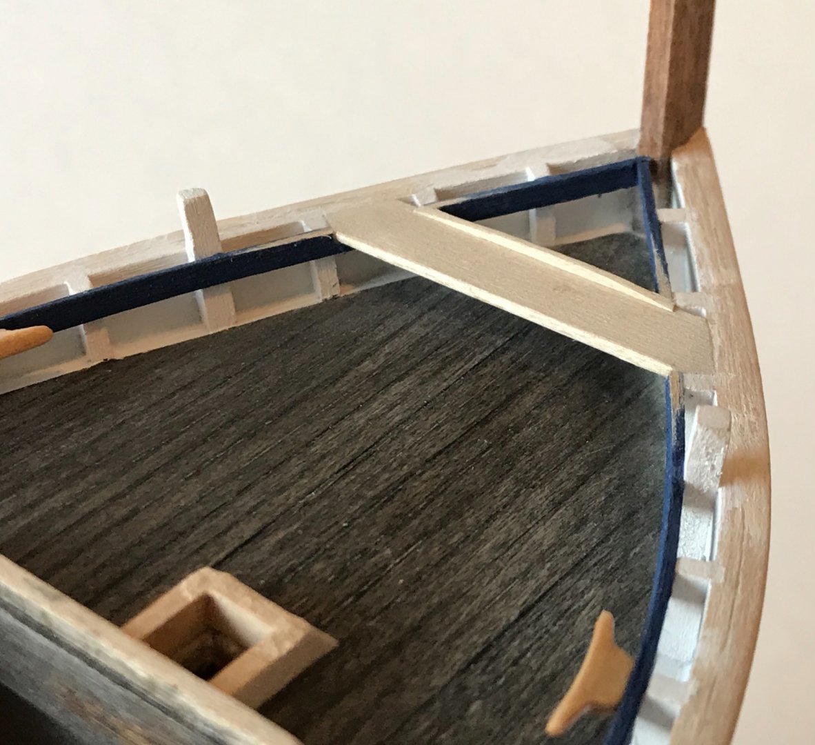
Cleats were made and affixed to the "bearer."
-
-
-
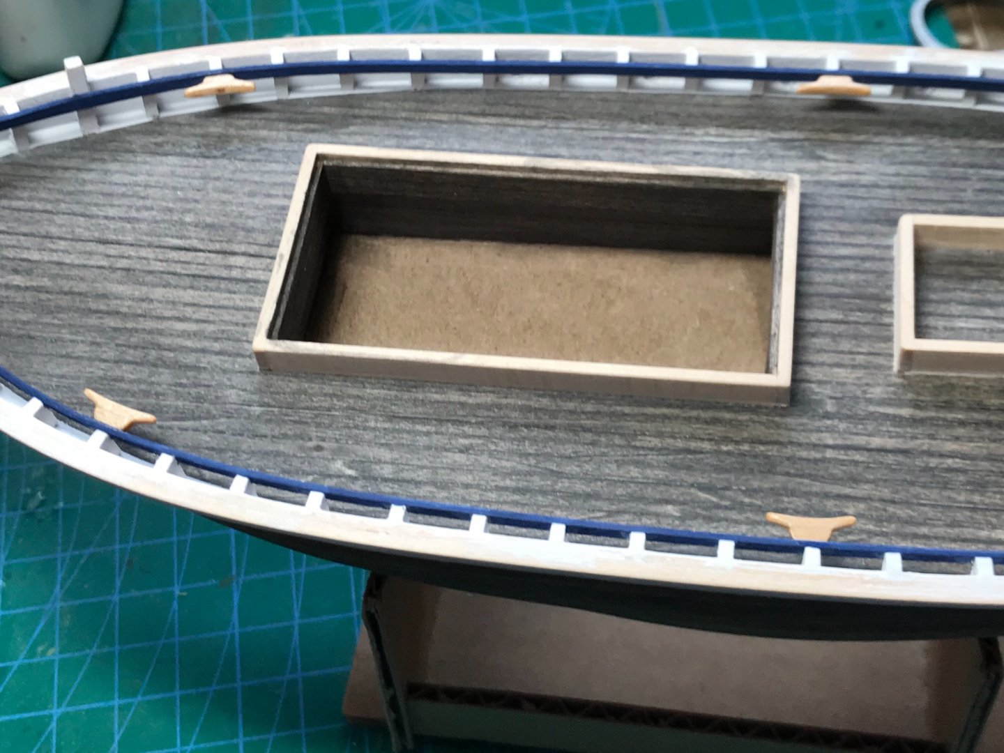
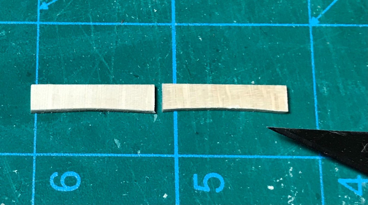
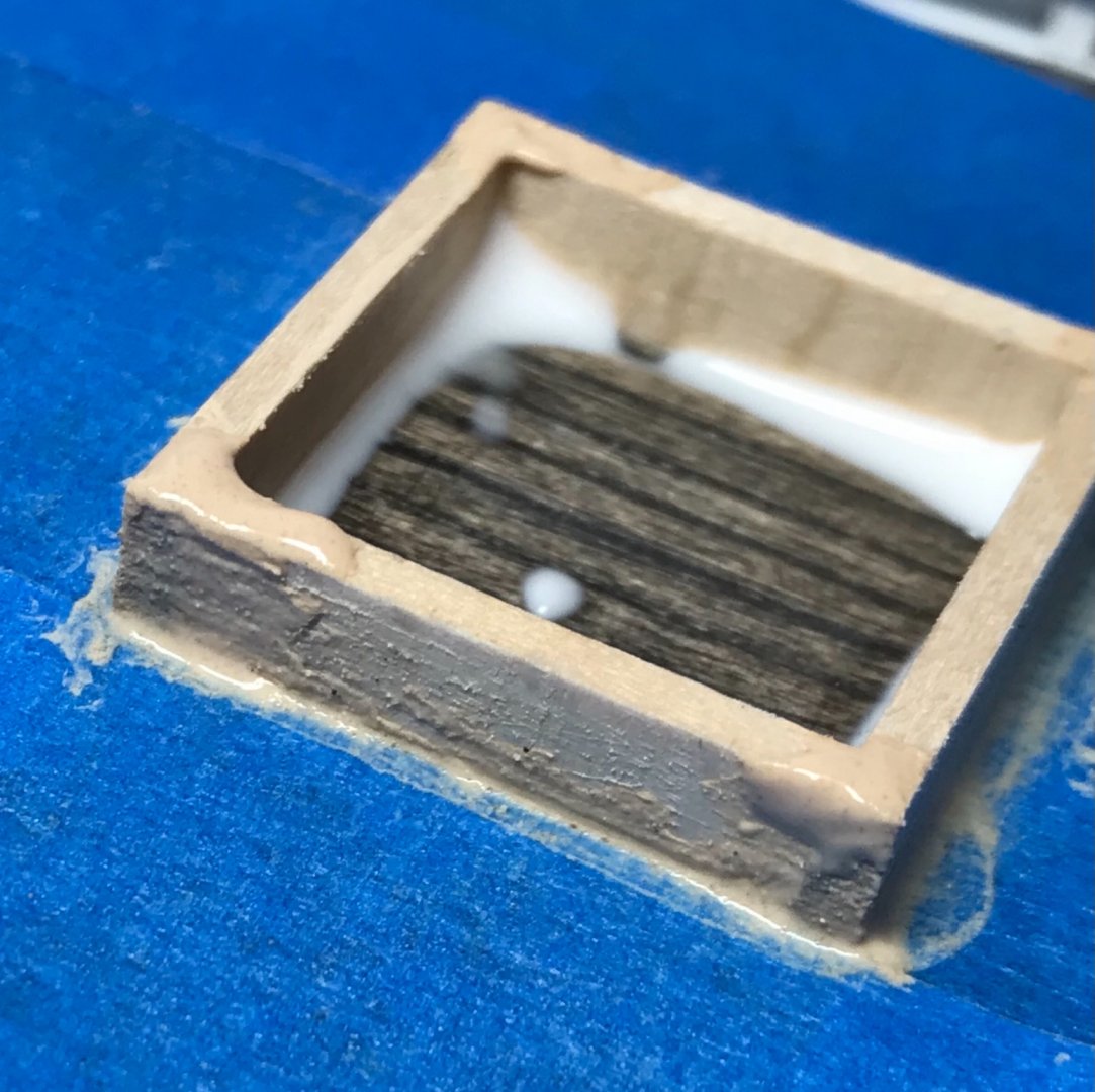
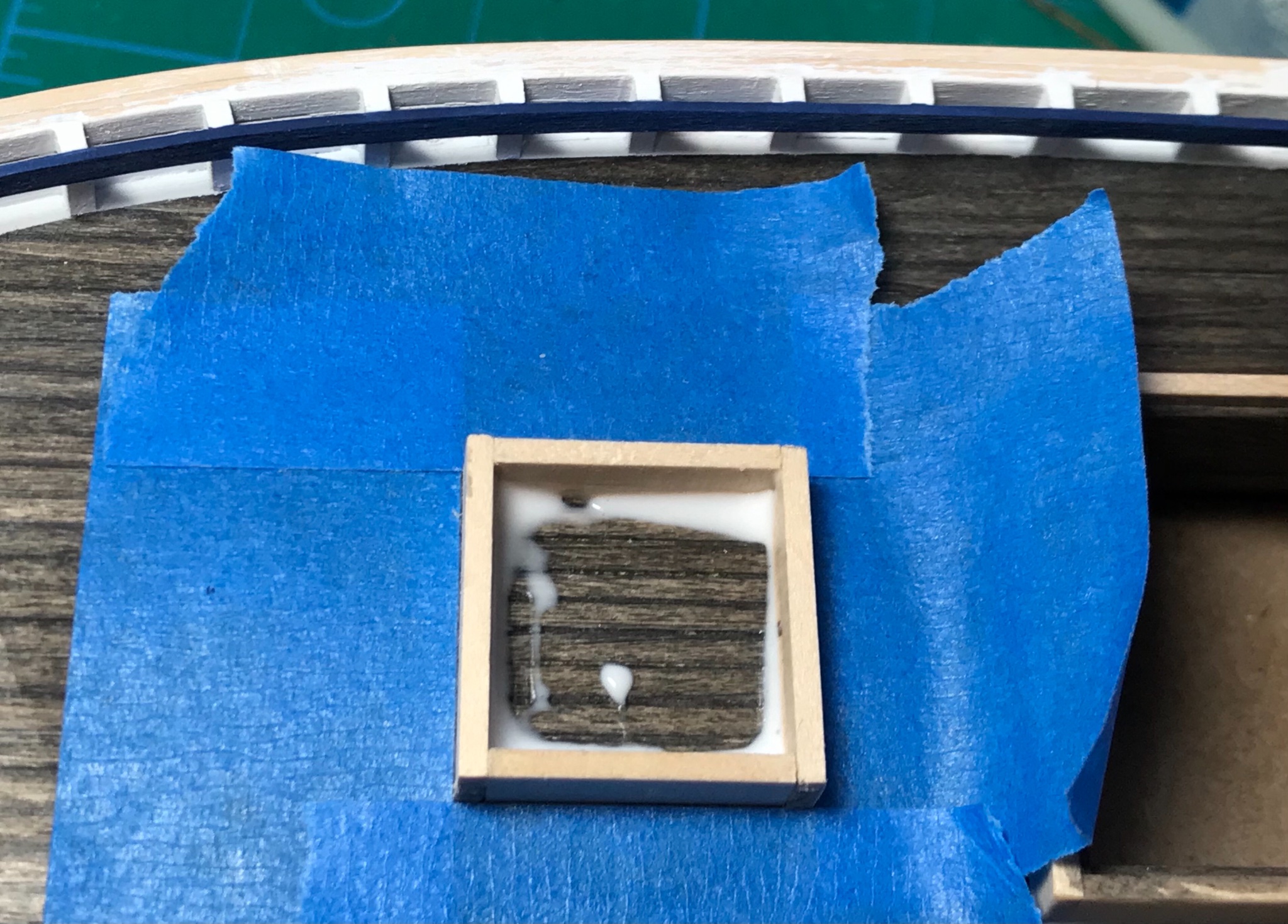
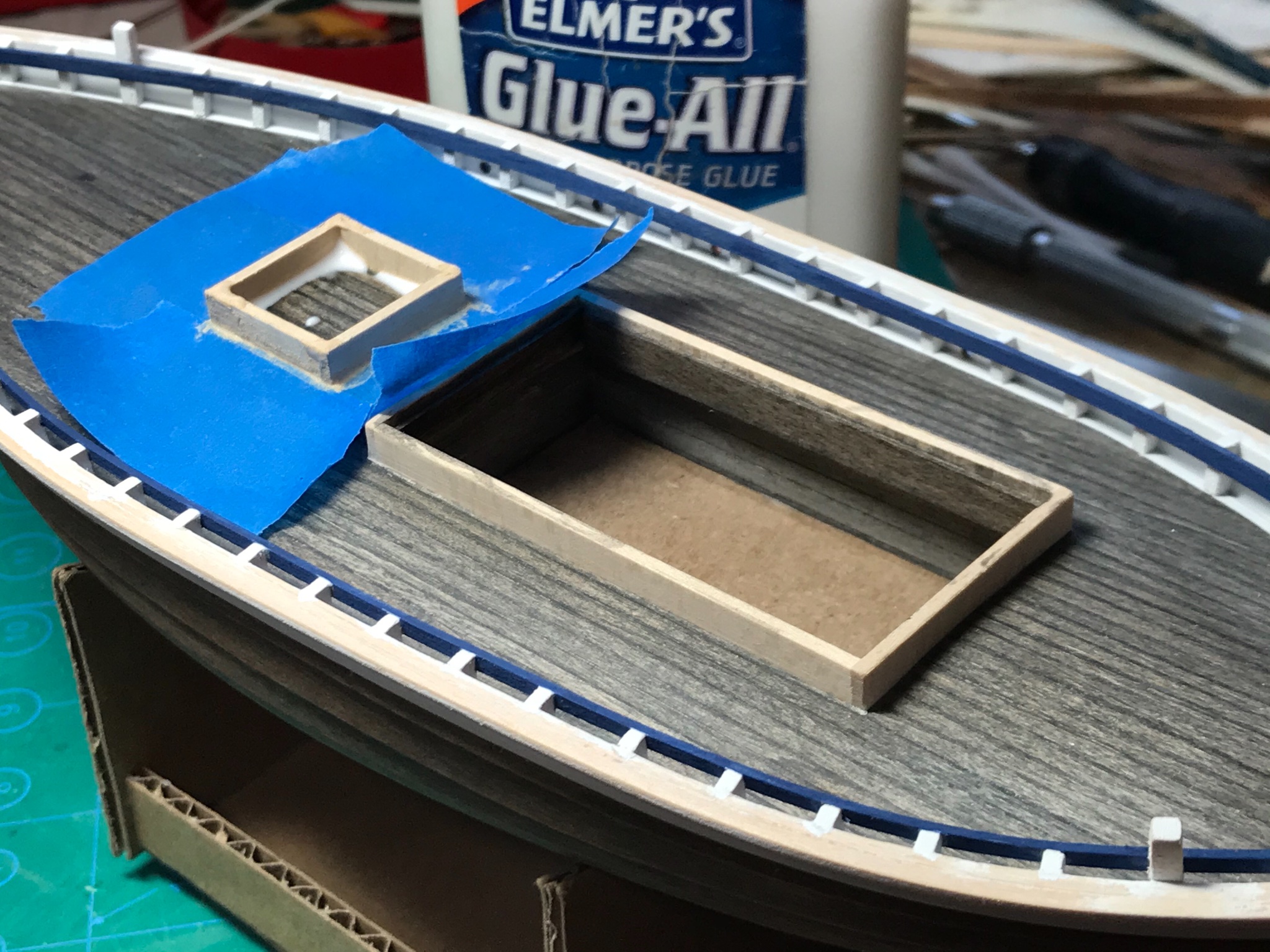
Today I worked on the hatch coamings. Basswood strips were used for the coamings and hatch covers will be built later. I plan to have the main hatch partially open, with nets visible and sowed. The smaller fore hatch will be closed.
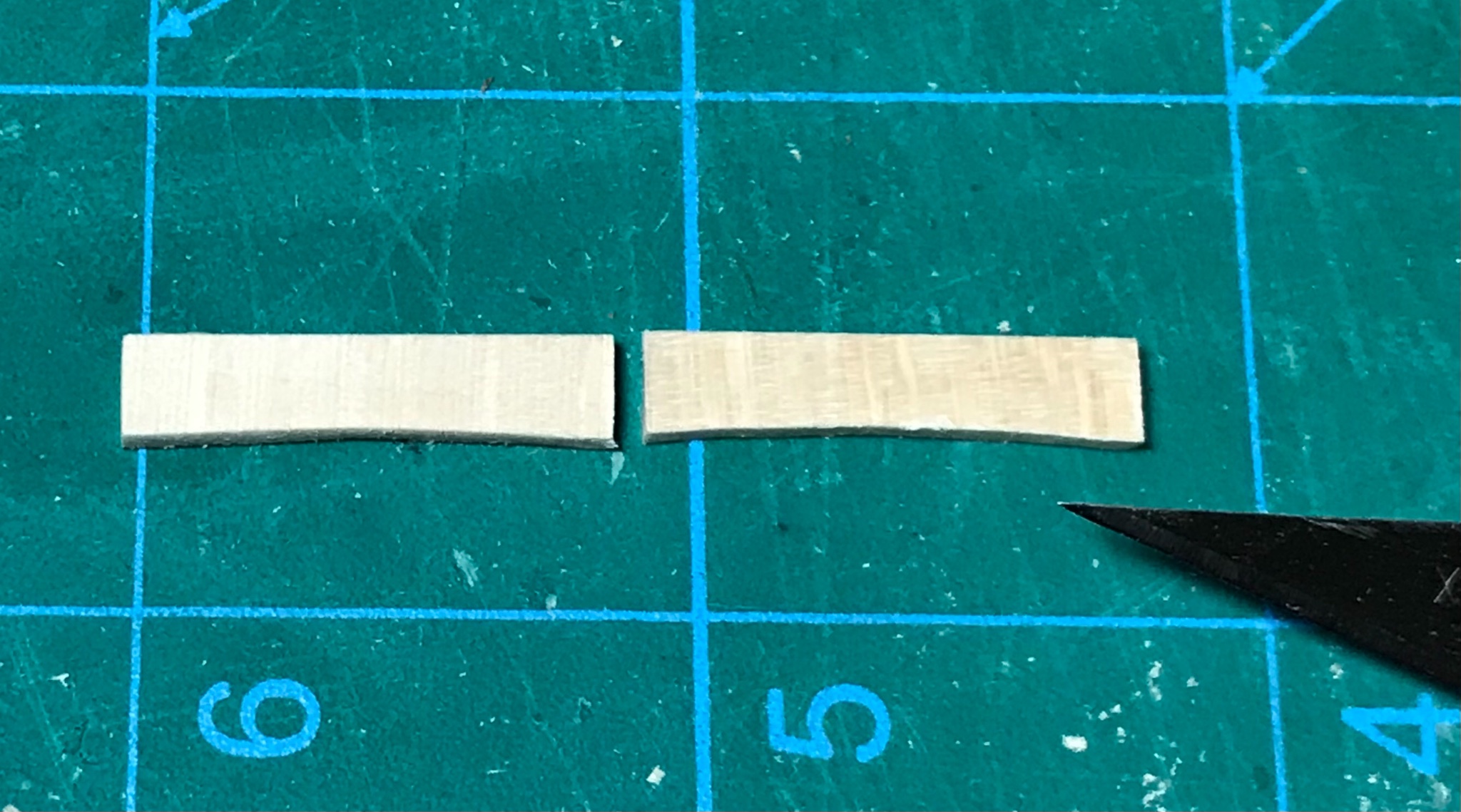
The sides of the coamings that go across the width of the deck need to be filed down to accommodate the camber in the deck. I use a half inch dowel with sandpaper glued to it and round files to help create the curve.
The coamings are glued in placed with PA white glue. I also use a mixture of acrylic wood putty, PA glue, and a little water to make a sealant for the seams. The blue masking tape protects the surface of the deck when I sand everything smooth.


- chris watton, egkb, Keith Black and 7 others
-
10
-
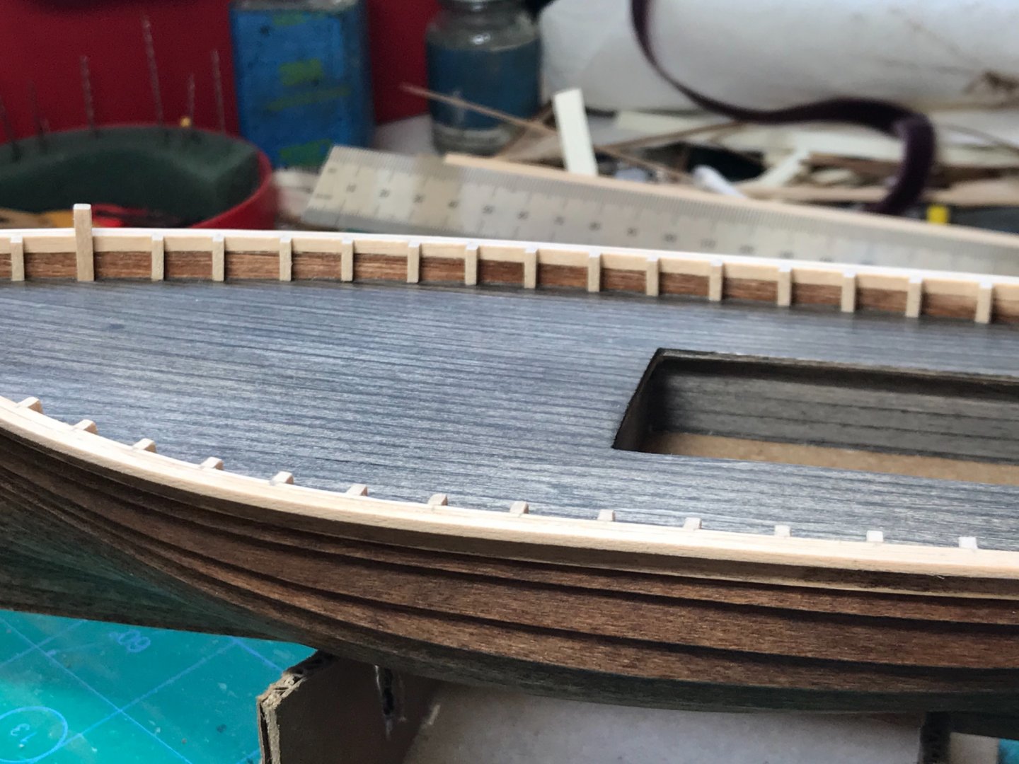
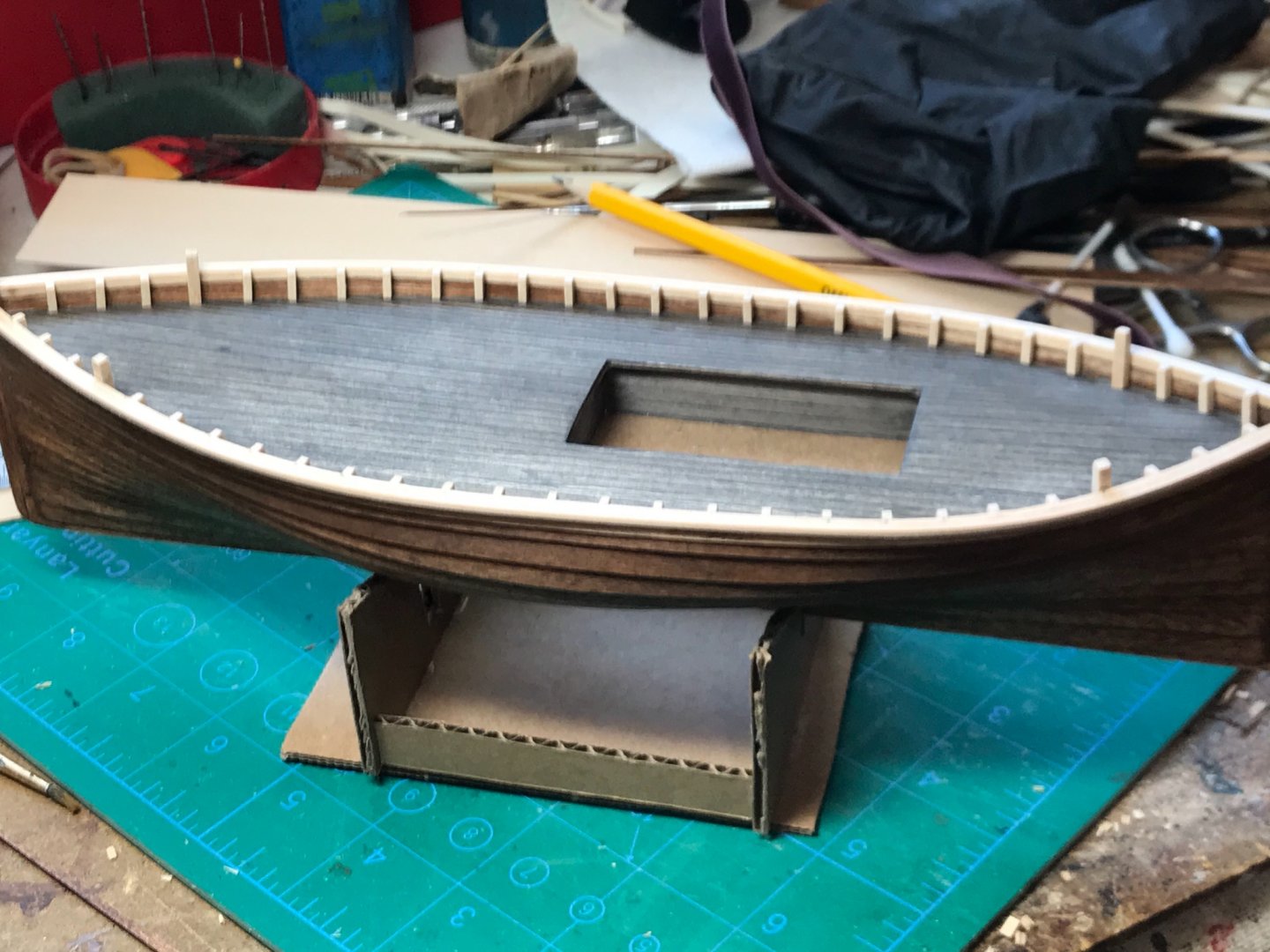
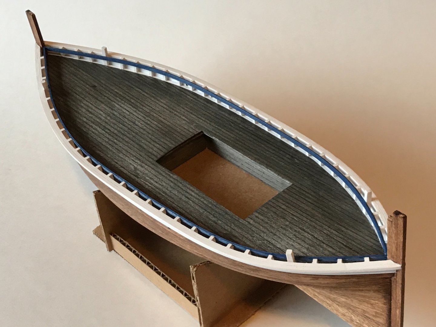
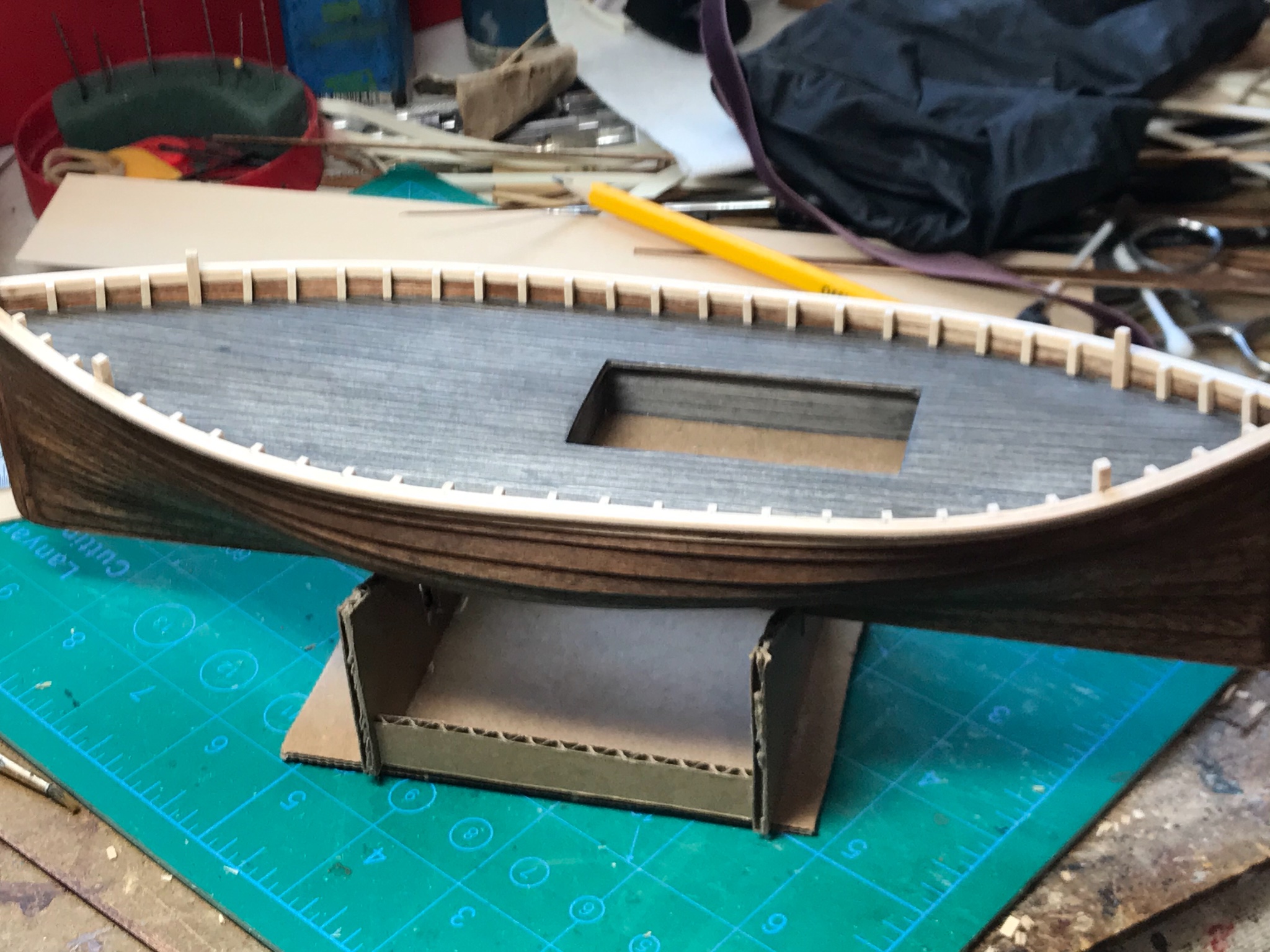
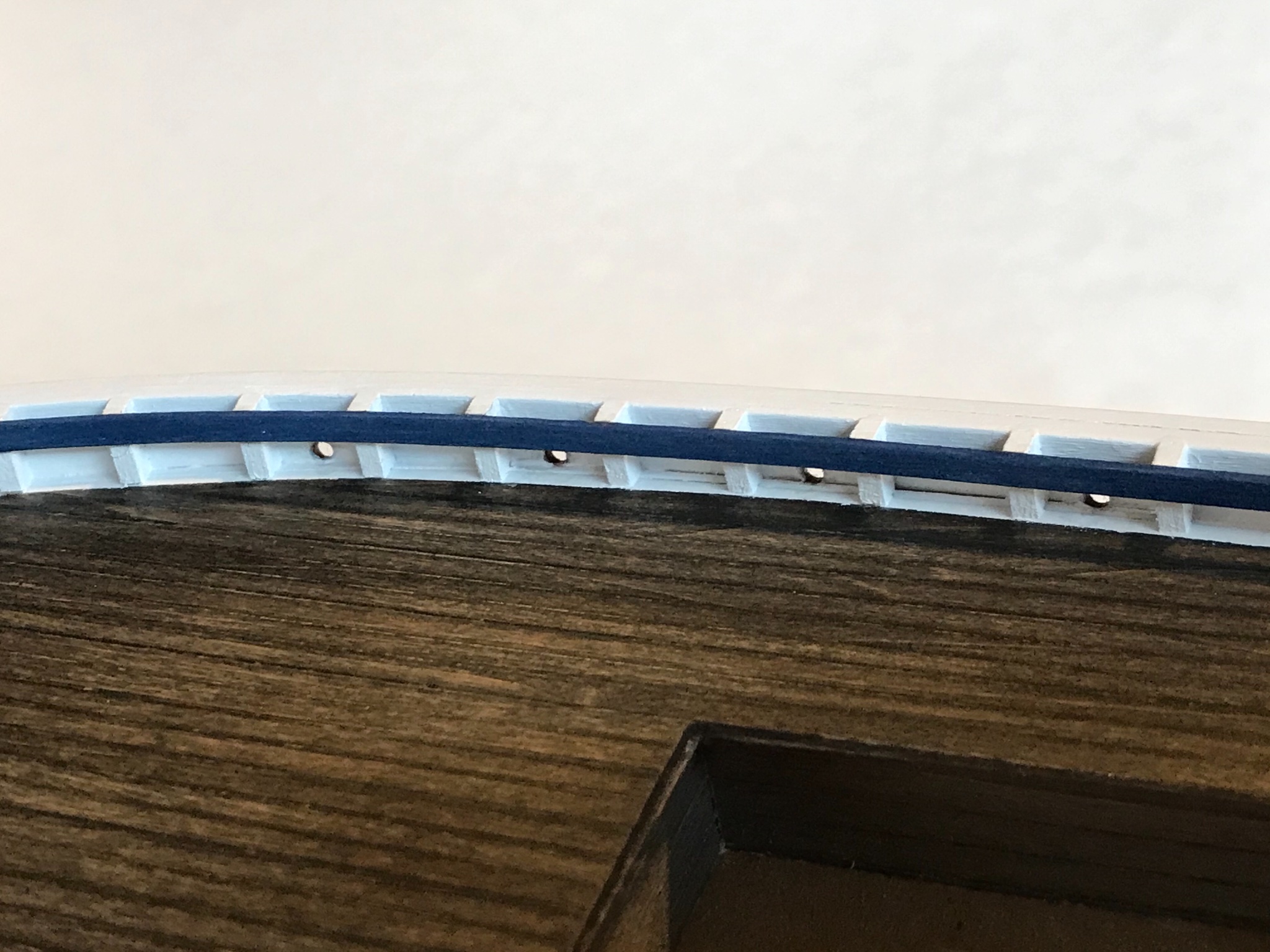
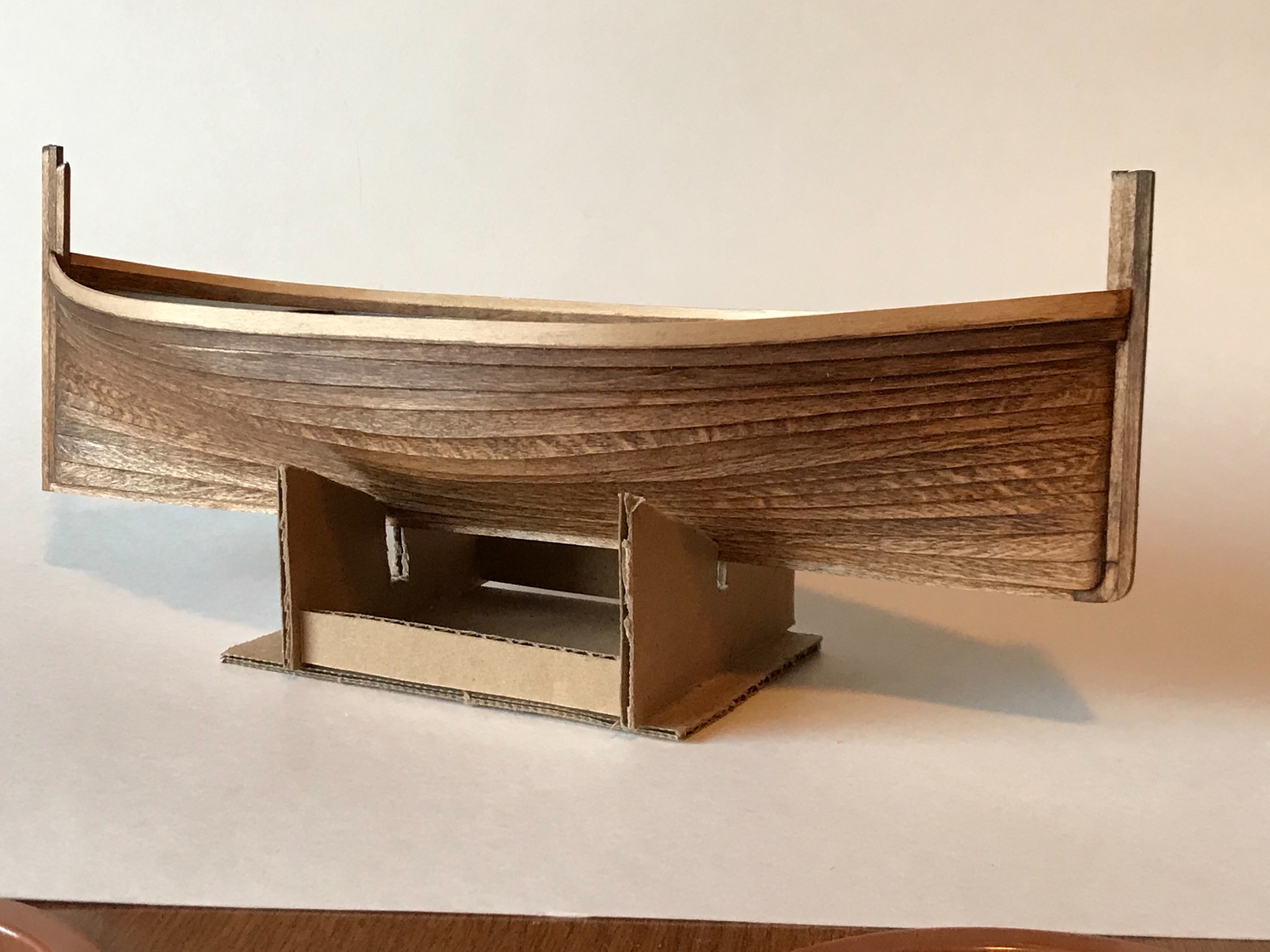
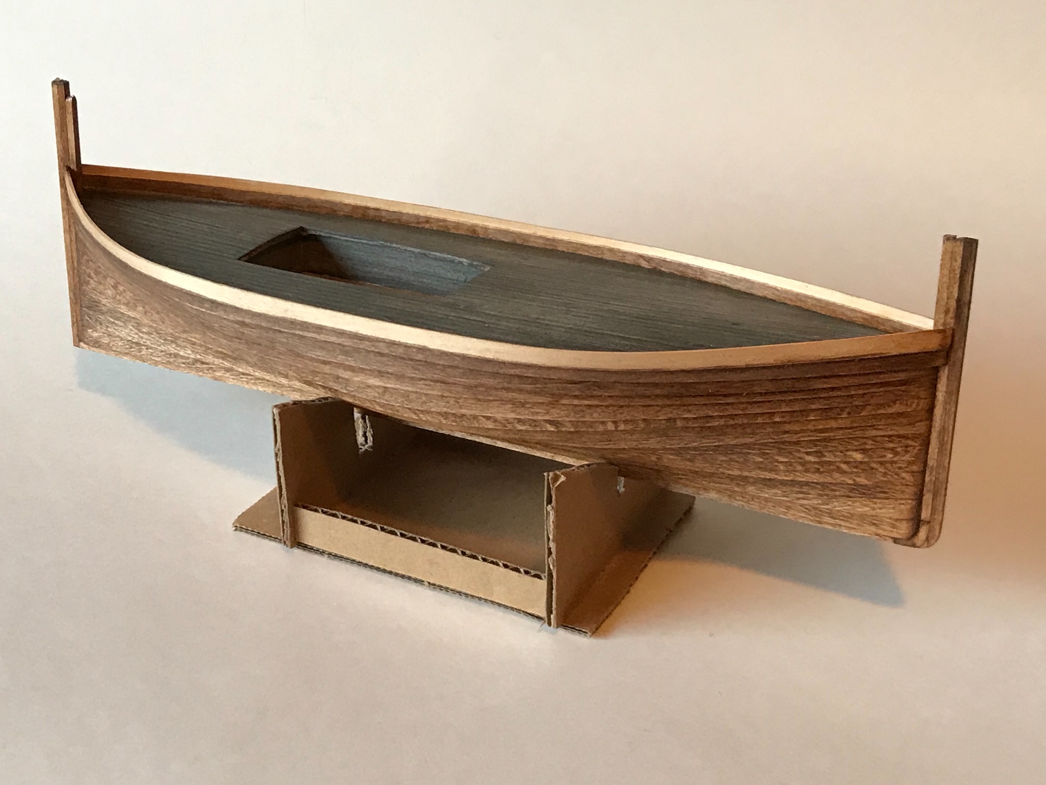
Added a plank along the top of the interior bulkhead to form a flat surface. This eliminated the "step" formed by clinker planking. Then the "false" frames (timberheads) were installed flat along the interior wall, including four taller/thicker timber-heads, presumably used as bollards. Finally, an outer gunwale strip and an inner "bearer" strip were added, and the scuppers were drilled out.
After installing the frames and gunwale, some painting was necessary before the bearer was installed (because I wanted it a different color - blue). The gunwale will eventually be blue too, which should be a nice contrast with the (now) white bulkheads.
Painting was done with an airbrush using Tamiya flat white acrylic model paint. The masking was done with both Tamiya and blue masking tap. It took a few hours to set-up the tape, but this seemed easier and promised better results (maybe) than brush painting. The blue paint was brushed on the bearers before they were glued to the timberheads.

- Roger Pellett, Keith Black, wefalck and 6 others
-
9
-
3 hours ago, longshanks said:
An entertaining build full of useful information.
End result is a fine tribute to these beautiful boats
Kev
Thanks so much!
-
On 1/20/2021 at 4:51 PM, Keith Black said:
GB, that's a swell planking job, nicely done.
Thanks Keith!
- mtaylor and Keith Black
-
2
-
-
2 hours ago, wefalck said:
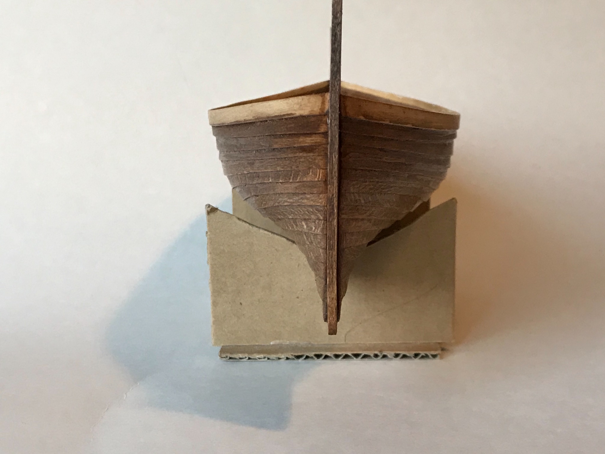
Depending on how sharp the bow (and the stern here) are, the overlapping section of the lower plank would be sharpened out to near zero over a distance of several plank widths - is it that what you did ?
I agree, that clinker-planking can be a bit of challenge, but if it worked, it is very satisfying.
I am beveling the lower edge of each upper plank to near zero for about 5 or 6 plank widths. It seems easier to do it that way (modeling-wise) as the plank is fitted and applied.
- mtaylor and Keith Black
-
2


Fifie by Gbmodeler - FINISHED - Scale 1:48 - Typical late 1800s Scottish Herring Drifter
in - Build logs for subjects built 1851 - 1900
Posted
I think you are right. It's hard to see the finer details in the historic photos I have, and what I installed are more like bolt ropes...