HOLIDAY DONATION DRIVE - SUPPORT MSW - DO YOUR PART TO KEEP THIS GREAT FORUM GOING! (Only 13 donations so far - C'mon guys!)
×


tkay11
-
Posts
1,827 -
Joined
-
Last visited
Content Type
Profiles
Forums
Gallery
Events
Everything posted by tkay11
-
 Thanks, Gabe. The main motivation (apart from developing skills in making plank-on-frame models) was really to learn for myself and give anyone who's interested some understanding of how these ships were built. Almost nobody in my circle of acquaintances has much idea that there's even a hobby devoted to this kind of thing, let alone full builds, so they're quite intrigued, and, as I had guessed, simply cannot see the blunders that are glaringly obvious to my own eye -- and that's exactly as it should be. Tony
- 132 replies
-
- 3
-

-
- triton cross-section
- cross-section
- (and 1 more)
-
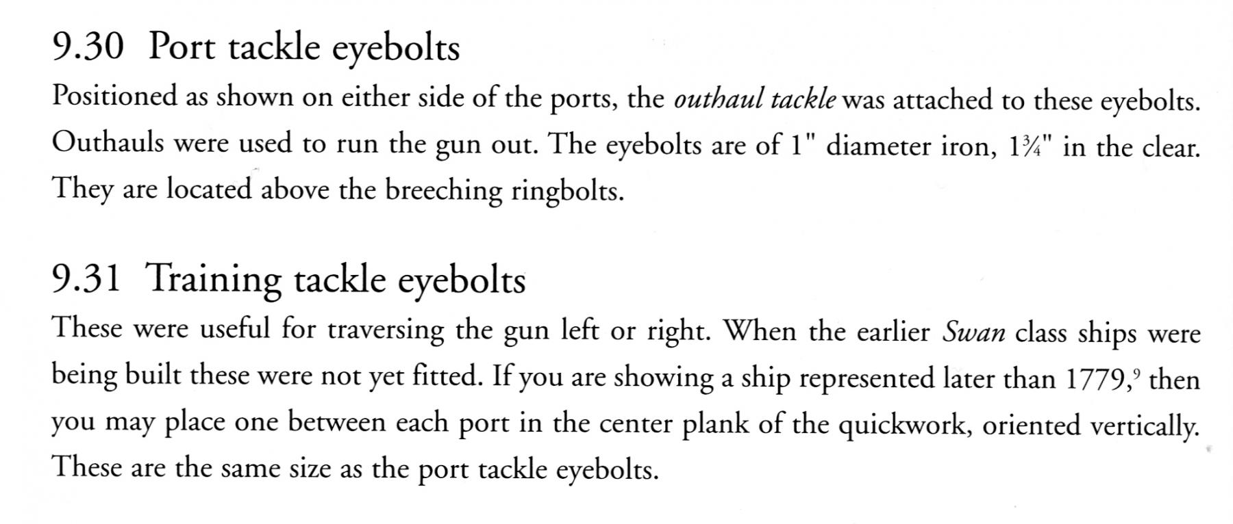
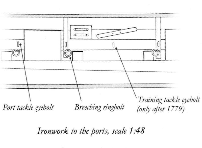
Here's another thought. David Antscherl specifically says that the training tackle eyebolt was only put in after 1779. The HMS Triton cross-section we are building is of the 1773 ship (I think). So unless it was re-fitted after 1779 I suppose it didn't have any training tackle eyebolts at all! In which case I don't have to put them in, and I can discard that version of the plan (GunDetailLayout.pdf) that's placed with the full build drawings. Well, that was an interesting discussion! Tony
- 16 replies
-
- 3
-
-
- Gun tackle
- Triton cross-section
- (and 2 more)
-
Thanks, Anguirel. It's interesting to see Lavery's take on it. David Antscherl provided an illustration which may help others who want to position the bolt for the training tackle: His description is as follows: Tony

- 16 replies
-
- 2
-
-
- Gun tackle
- Triton cross-section
- (and 2 more)
-
As usual, I continue to enjoy your log and the way you approach the build. It is very interesting how different model building can be from real ship building. I came across the restoration of the Pilgrim Brixham sailing trawler, a Cutter-rigged ketch, at http://pilgrimofbrixham.co.uk/history/ In the video of the build on that page it is quite clear that there's a contrast between the visible imperfections on the internal fittings, and the eventual smoothness of the external and visible finish. Also, on the deck and hull planking, I really can't see the treenails in the still photos. Of course, this is a modern restoration, but it made me think about the conventions of the modelling we do. I suppose this is by way of saying that your build is still great even though you worry about the small imperfections such as gaps that have to be filled or colour mismatches fixed. In real life gaps were filled and paint did a great job. Tony
-
Thanks, Pete. Actually, I had been hoping the thread centred on the outlying training tackle. The training tackle bolts are quite separate from the port tackle bolts (according to David Antscherl's Fully Framed Model Vol II, which I should have checked earlier at he discusses them clearly), so at least they co-existed. As to whether the tackle co-existed it'll be interesting to see what the experts say. I would have thought it might get in the way whilst the guns were in normal use and only used whilst training through an arc. As you say, interesting discussion! Tony
- 16 replies
-
- 4
-
-
- Gun tackle
- Triton cross-section
- (and 2 more)
-
Thanks a lot, everyone, for the very informative replies and the link. I had suspected the bolt was for the training tackle, Mark P, so thanks for that detailed analysis. I'd better go out and practise my gunnery now, so that I can get a good feel for it. Tony
- 16 replies
-
- 5
-
-
- Gun tackle
- Triton cross-section
- (and 2 more)
-
Thanks for the amazingly quick replies! Russ: I thought he port tackle went to the rear eyebolt on the carriage. Is that correct? I had been thinking it might just be the training tackle which would only be used when traversing the guns left or right. Anguirel: Would that be attached all the time or only after being run out by the port tackle? Tony
- 16 replies
-
- 3
-
-
- Gun tackle
- Triton cross-section
- (and 2 more)
-
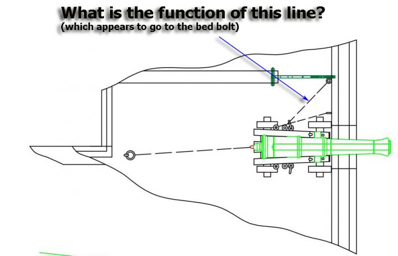
I am preparing to make the guns for the Triton cross-section, but have been puzzled by a line to the bed bolt shown in one of the drawings. The line in question is shown below. I'd be grateful if someone could explain its function. I can't see it in any of the other builds I have seen, so wonder if it is necessary, or illustrative of something only occasionally used. Thanks, as usual, for any guidance! Tony
- 16 replies
-
- 3
-
-
- Gun tackle
- Triton cross-section
- (and 2 more)
-
And best wishes of the season to you too, Dirk, and your enterprising partner! Tony
- 132 replies
-
- 3
-
-
- triton cross-section
- cross-section
- (and 1 more)
-
Thanks, Mark. Even I was surprised at the change a drop of oil makes. Turns it from banal to something even my wife liked! I'll have to try some on myself. Tony
- 132 replies
-
- 6
-
-
- triton cross-section
- cross-section
- (and 1 more)
-
Thanks, Chad and Dirk! I feel slightly ashamed (edit: maybe 'embarrassed' would be a better word) when given such encouragement from those whose work I admire, since I don't think I'll ever produce work that's as beautifully finished and precise -- but it is indeed encouragement and much appreciated at that! And I certainly enjoy learning from you, so keep on building and logging if only for my benefit! Tony
- 132 replies
-
- 4
-
-
- triton cross-section
- cross-section
- (and 1 more)
-
Ooops! I've only just recalled that all this is a re-post of a long-finished build! I've edited comments to suit. Sorry about that! Tony
-
And while I posted the last message, you've already posted your recovery! I'm only just recalling that all this is history! Tony
-
Totally agree about the value of making your own scrapers. I wish I'd done my rabbet like that now I've used a scraper for the waterways. On the tacking down of the templates, I use a water-based glue stick (Pritt stick in the UK) for two reasons: 1. It's easy to put on, and so if an edge lifts off it's really easy just to dab at it with the stick. 2. It's much easier to remove than the contact adhesive rubber-based glues. All you have to do is paint it over with a brush or dab with a sponge. I also agree about the learning you've done. On my previous and first build I found that on average I had to make something twice over before I'd get it right a third time. There are some people here who've even built a near complete ship only to find it was absolutely necessary to start all over again. If you see it as learning, as you've done, then the pain is very much less! On my Triton build I've had to do quite a bit of insertion of wood pieces to make up for over-rigorous sanding but oddly enough that's a skill I've really enjoyed learning. Looking forward to the recovery stages! Tony Tony
-
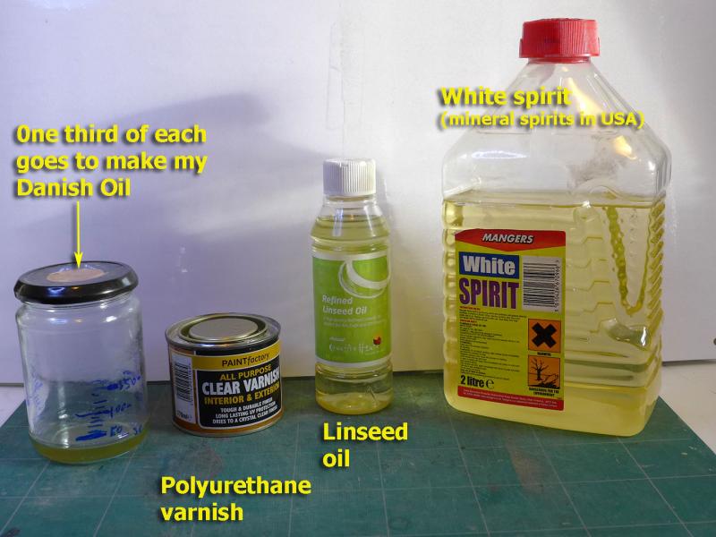
Thanks to various comments (notably Dirk's -- thank you Dirk!), I decided to experiment a bit with oils. I decided in the end to make up my own Danish oil, seeing that I already had the ingredients. I followed the advice given by Bob Flexner at http://www.popularwoodworking.com/techniques/finishing/oil-finishes-their-history-and-use The recommended dosage to start with is one-third of each, so that’s what I mixed. I liked the results, so that’s what I’ll stick with for the rest of the build. I planked just over half the gun deck, along with the lower strakes of the gun deck walls. I then oiled the inside of the lower walls and the two decks -- leaving the outside of the frames and the wall planking above the gun deck. I need to finish the planking of the gun deck walls, sand down the fore and aft section faces, and then I’ll be working on installing the eyebolts for the cannon and making up the gangway brackets. Tony

- 132 replies
-
- 14
-
-
- triton cross-section
- cross-section
- (and 1 more)
-
Very interesting, Dupree. My brother-in-law is going to be carrying over Ed Tosti's two Naiad books for me early in January. Great minds! Tony
-
I really enjoy build logs like this where every step, including problems, is shown. Thanks very much. Tony
-
Thanks for the likes! Dupree: TurboCAD is for me an almost essential aspect of the model as it allows for accurate part making, dimension checking and making all sorts of jigs. As for making mistakes I agree they're an essential part of learning. That's why I try to highlight the ones I make for others to learn from as well. Dirk: thanks a lot for the suggestion. It's a good one, as always. I'd thought about oil but then was worried about putting it on surfaces that were to be glued. Anyway, when I've finished assembly I'll practise with oil as you suggest. I always enjoy learning! Tony
- 132 replies
-
- 3
-
-
- triton cross-section
- cross-section
- (and 1 more)
-
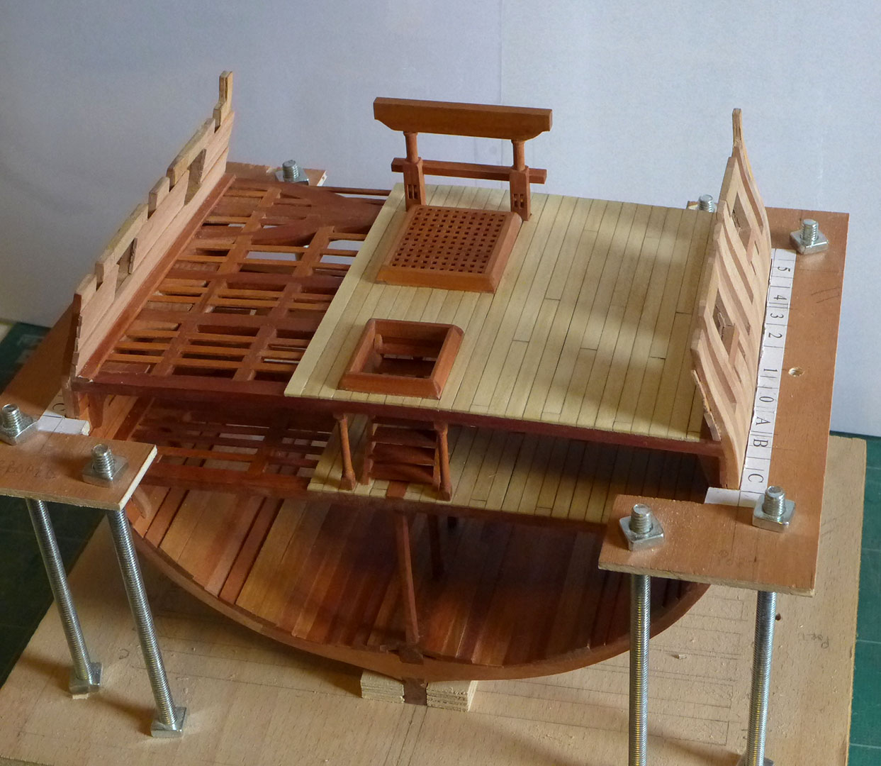
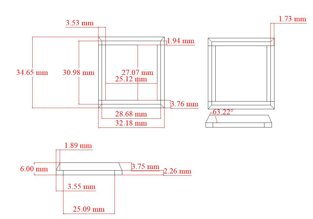
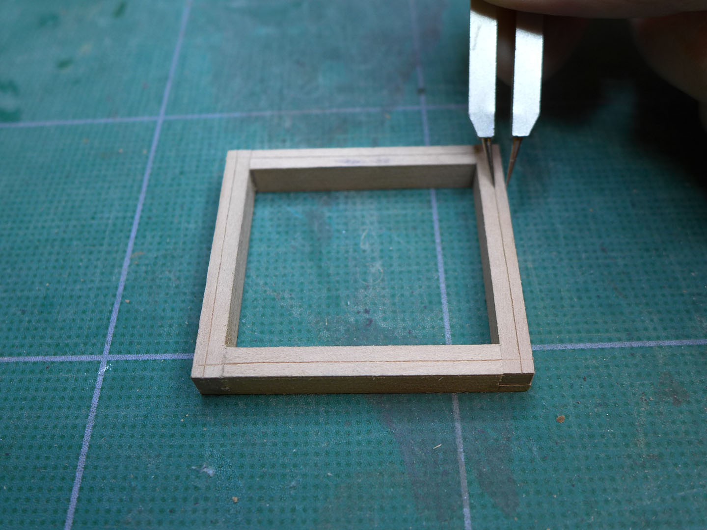
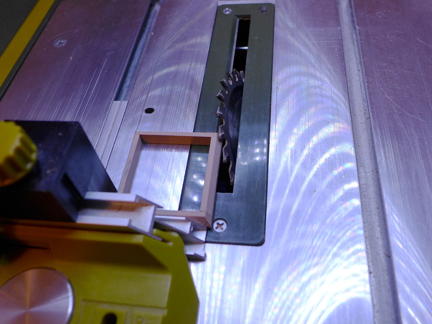
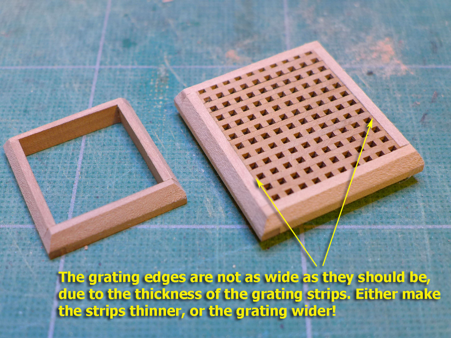
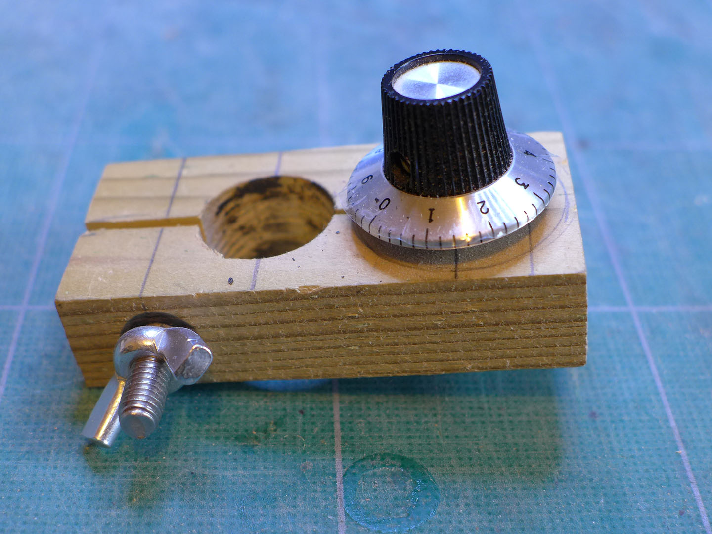
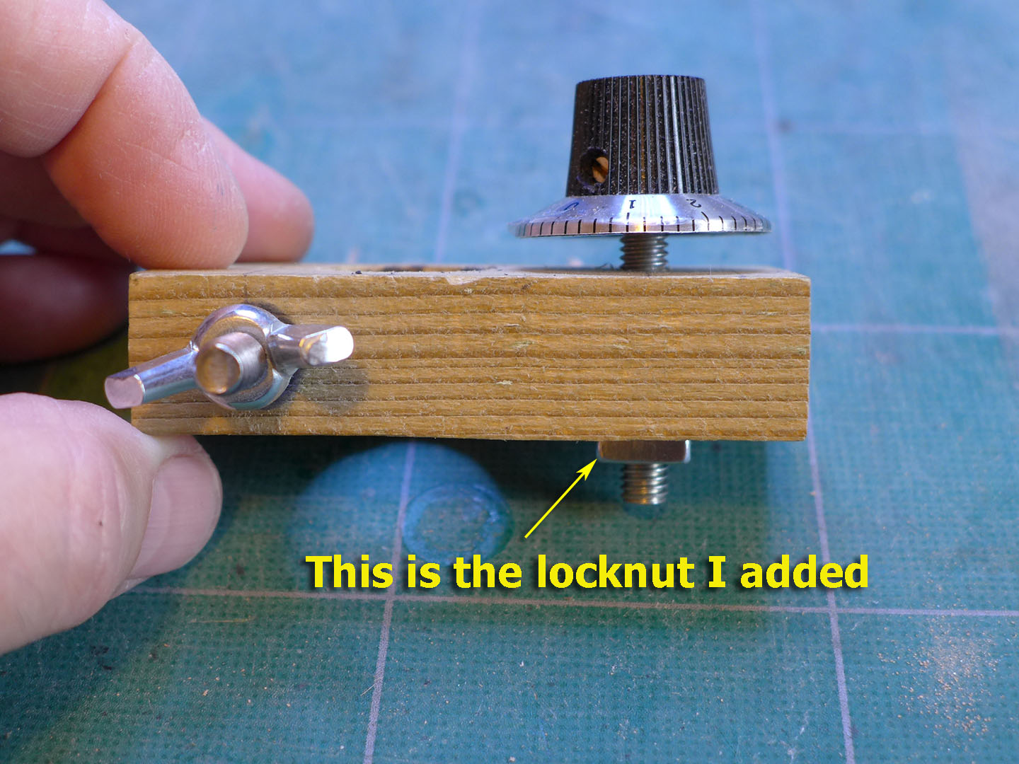
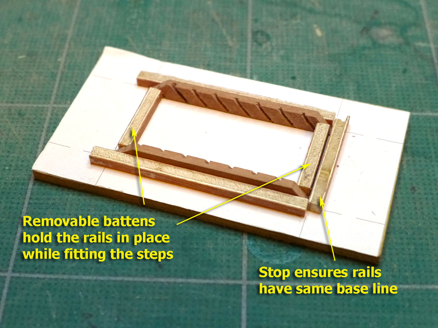
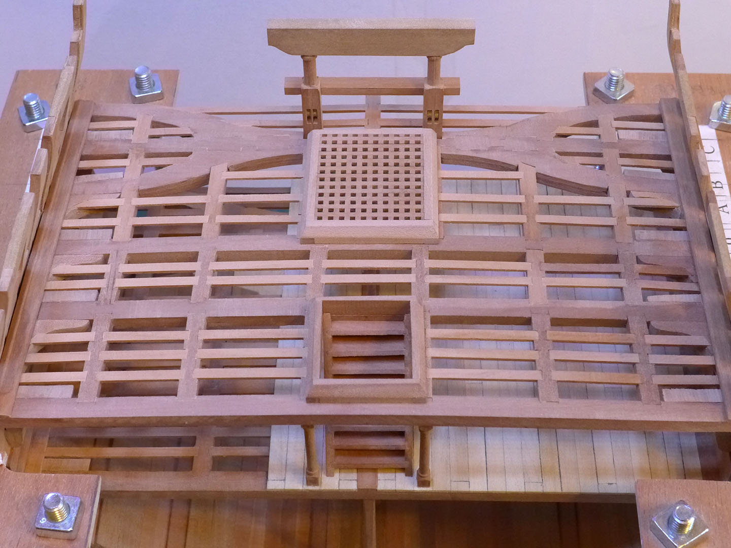
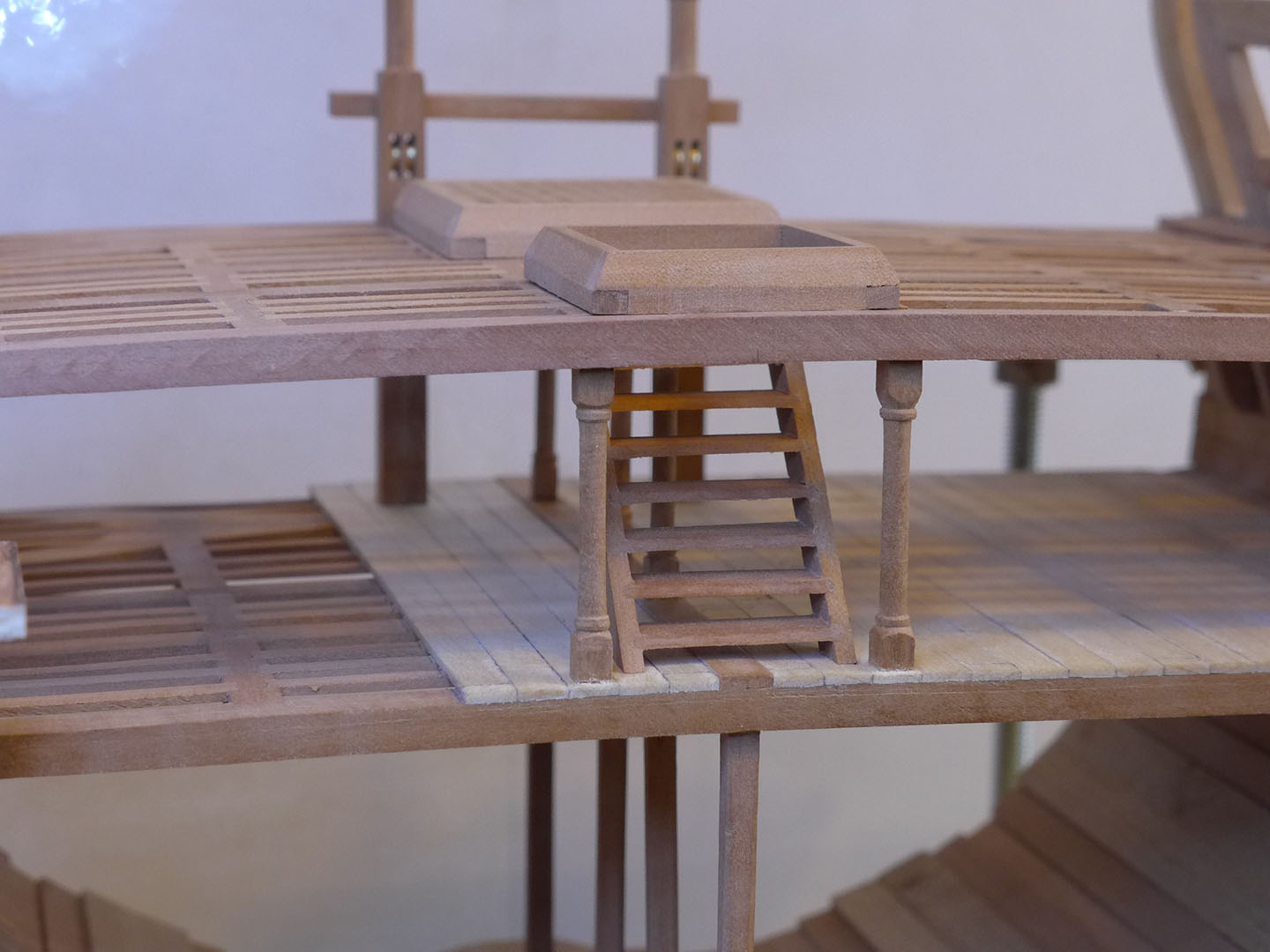
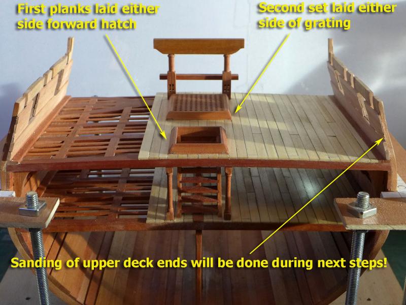
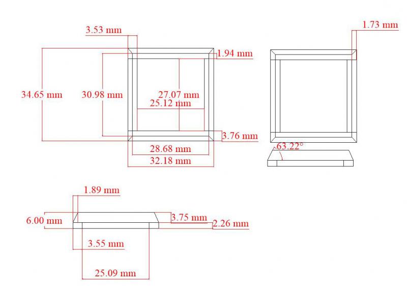
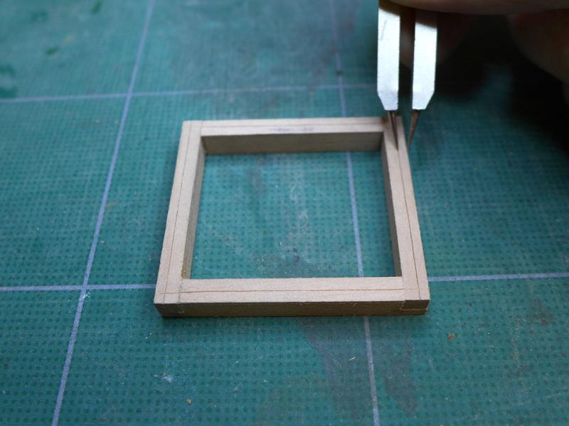
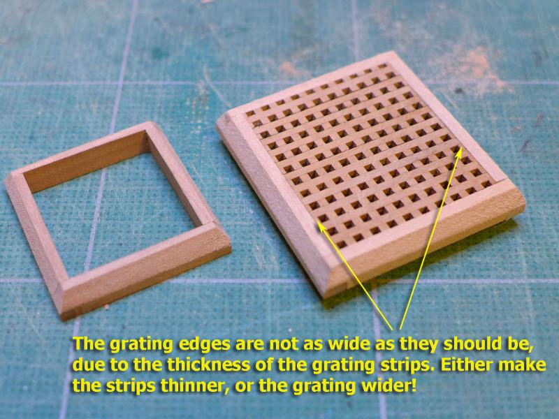
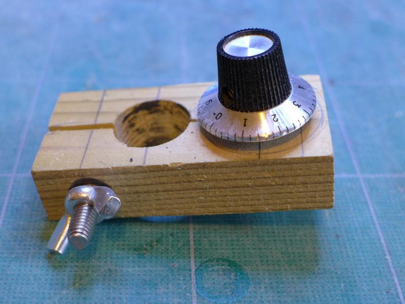
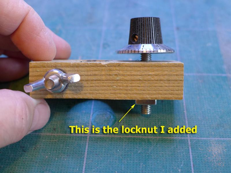
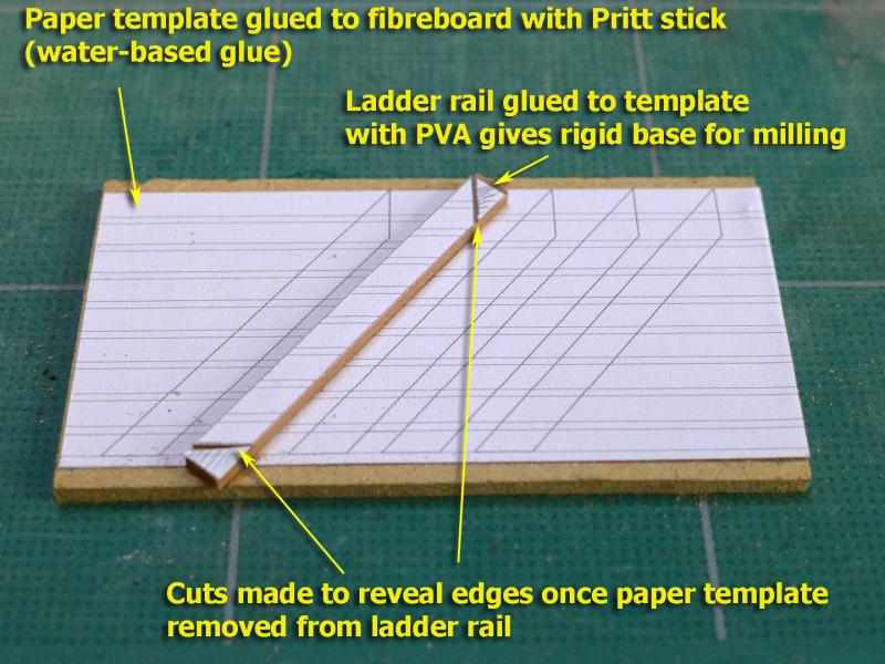
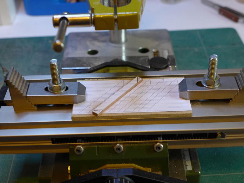
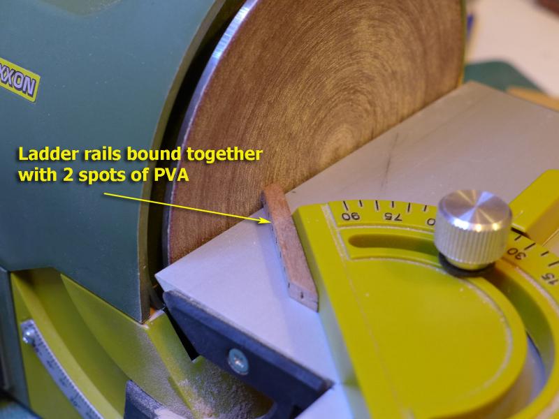
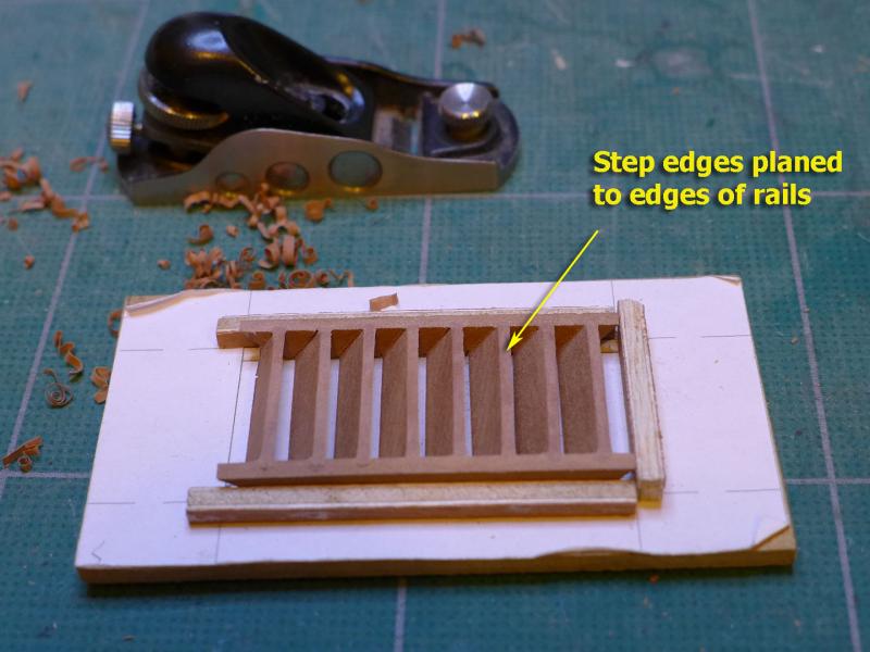
COAMINGS AND GRATING The joints were made as usual with the Proxxon saw. To cut the angles (63 degrees) I first inscribed the top edges by 1.73mm using dividers with the measurement derived from the TurboCAD programme. This then allowed me to use the saw at an angle which has a nicely accurate indicator in degrees. I edged the coaming towards the saw until it cut right at the line. By the way: if you do this, WATCH OUT FOR YOUR FINGERS AS YOU MAY FORGET THE EDGE OF THE SAW COULD BE CLOSER TO THEM THAN YOU THINK! I was wary of this, but thought I’d better mention it in case others might not have thought about it. Having made the coamings, I could now install the grating I made earlier. I now realised that the long edges could not be the same width as the grating battens if they were to fit into the coaming I had made. I reckon I must have made a very slight error in cutting the strips, but thought that I might well make the same kind of error again so I went with the grating as made. You might well note that I've not curved the top of the grating to match the deck camber. My decision was the lazy one -- I followed the plans! As for the base of the coamings, where curvature would come into play, again I was lazy -- the tiny cracks at their base sides will be covered by the planking. One small point to watch out for is that if you stick too closely to the plan measurements it is vital to check these against the actual measurements you achieve on the model. In my case the forward hatch I made came out 0.5mm less wide than on the plans, but as this was not going to affect anything except the width of the ladder, I kept the hatch I made. LADDER I debated a while as to how to make the ladder. Essentially the choice was between table saw, hand saw and mill. I decided the easiest would be to use the modified Proxxon drill stand that I made for the Sherbourne. You can see the design at http://modelshipworld.com/index.php/topic/4539-how-to-modify-proxxon-mb-140-drill-stand-to-act-as-mill/?p=130660. I made a very slight modification to that modification by adding a locking nut below the screw adjuster. This was because I found that vibration during milling made the screw gradually move upwards. You can see this further modification in the following pictures: The next question was how best to hold the ladder rails in place while milling. I made a paper template and glued that to a rectangle of fibreboard using water-based glue (Pritt stick). After fiddling around clamping the rails to the template I decided to experiment and see if gluing the rail to the template would allow a sufficiently strong bond for milling. I used PVA to do this and it worked very well indeed – allowing me to remove the rail easily after milling with full-strength isopropanol, and allowing me to remove the paper templates from the fibreboard and the rails with a damp sponge. An additional benefit of this way of clamping is that it allows an uncluttered view of the rails whilst milling. I could then proceed by clamping the board to the micro compound table. To make the rails equal in height and at the correct angles, I bound them together with a couple of spots of PVA, then used the disc sander for the angles. I was really thankful that the Proxxon sander’s degree marker was accurate! I then made a simple jig for placing the steps. I again used the idea of gluing a template to the fibreboard base, then gluing battens to the template. To keep the rails apart while fitting the steps I made two temporary and removable battens from old plywood. PUTTING IT ALL TOGETHER This allowed me to assemble the coamings, grating and ladder. I can see from the results that I should really spend time sanding to achieve the glassy kind of finish that others have done, but for the moment I’m just pleased that I can make and put together all these pieces! Next I’ll do some planking. Tony


- 132 replies
-
- 21
-
-
- triton cross-section
- cross-section
- (and 1 more)
-
Yes, good idea. Tony
-
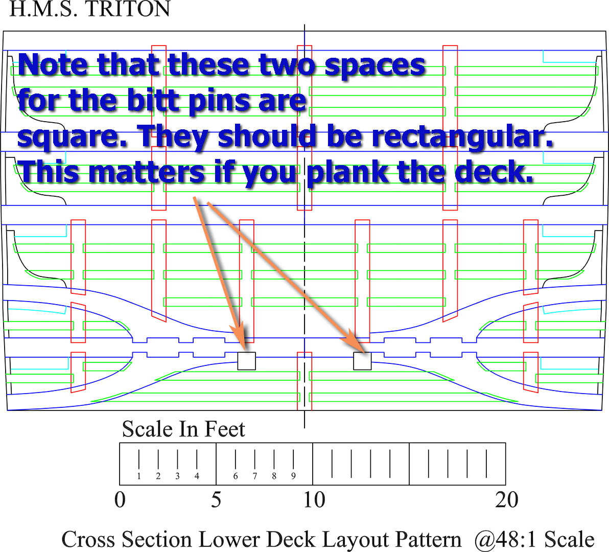
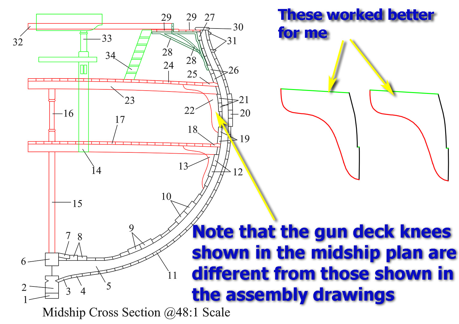
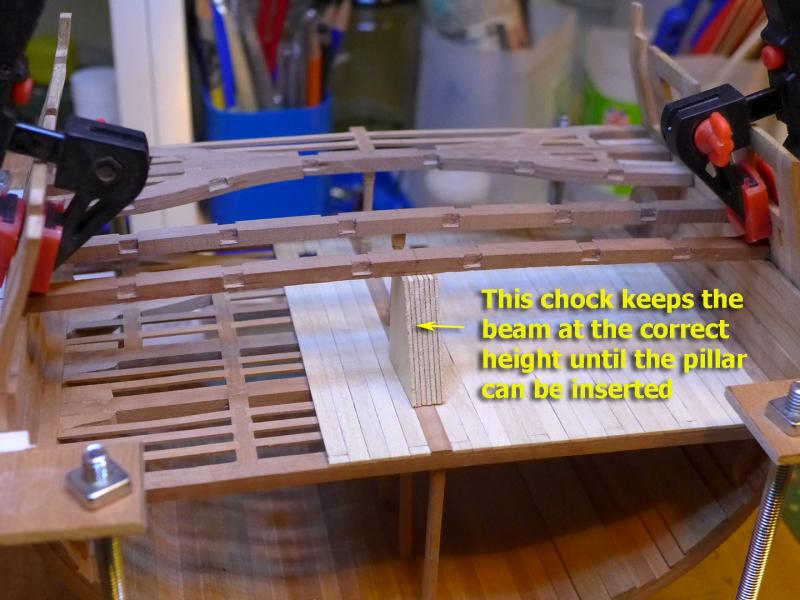
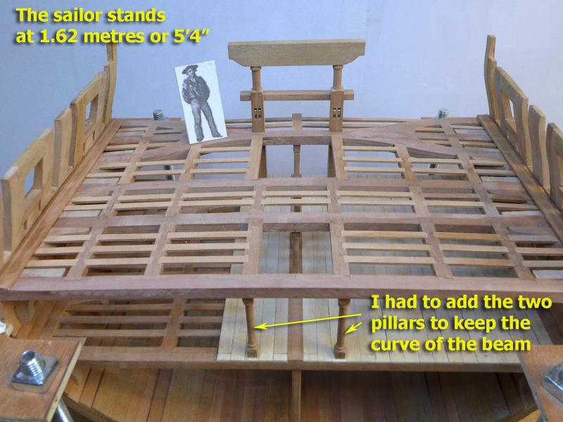
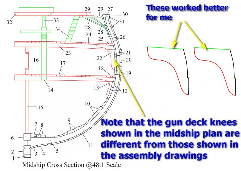
A NOTE ON MEASUREMENTS I thought I ought to mention a couple of possible difficulties for the unwary (i.e. myself!). The first was that I cut sections out of the lower deck for the bitt pins using the plans for the lower deck layout pattern. This shows the bitt pin area at that level as being square, whereas of course by then the pins are not square, but have been shaped into a rectangle. I decided to keep the square holes and keep the bitt pins square, but that is not how they should be! The next thing to point out is that the shape of the hanging knees for the gun deck shown in the ‘midship cross section’ drawing that you can find with the full plans are different from the drawing of two hanging knees for the gun deck you find in the cross-section plans. I started by using the ones from the midship cross section, but found that the more accurate ones were those shown in the cross-section drawings. PUTTING UP THE BEAMS Because I had chosen to bend the beams with heat rather than cut the beams to the correct curvature it became necessary to keep the beam at the correct height with the chock I had used earlier. This allowed me to ensure the beams were cut to the correct length before placing the pillar for each beam. As I like to be reminded of the scale of the model, I took a contemporary drawing of a sailor and sized him to be 5’4” or 1.62 metres high and placed him on the gun deck. The following shows the current state of the model with the waterways in place and the bitt pins placed but not yet glued as I’m still deliberating as to whether or not to paint them. You'll notice that I changed my mind about not adding pillars on either side of the stairs for the forward beam. I had to put them in for the simple reason that the beam did not retain its full curvature after heat bending. Next time I'll follow David Antscherl's advice and cut the beams to the correct curvature! Next up will be the coamings for the forward hatch and perhaps the ladder and the grating coamings for the after hatch. Tony

- 132 replies
-
- 13
-
-
- triton cross-section
- cross-section
- (and 1 more)
-
Great to see another Triton builder! I think the way the wood is sold depends on the supplier. If it's a timber merchant they often ask whether you want the wood planed or not. It looks as though your supplier expects you to plane or re-saw your own wood. Some merchants specialise in small cuts for modellers and generally they will let you have an exact specification. I don't know what country you're from, but if it's the USA then there are loads of specialist hobby timber suppliers that others on this forum will tell you about. Tony
-
Yes, it's quite a sizeable group of cross-sectioneers (and not cross sectioneers) now. That will reinforce the learning for all of us. Tony
-
Mini Mill recommendations
tkay11 replied to StebbinsTim's topic in Modeling tools and Workshop Equipment
Very helpful comment, John. Thanks. Tony -
Mini Mill recommendations
tkay11 replied to StebbinsTim's topic in Modeling tools and Workshop Equipment
I don't have any mill (apart from my modified one) and always pop my head in whenever there's a discussion about mills just to see what's changed over the years. I found the comment by jhearl very interesting bur very hard to assess because in Europe the Proxxon small mill, as has been said, is very popular indeed and used by many master modellers with much expressed satisfaction and the results are there to be displayed on their many web pages. We've also had so many discussions through the years of how the small Proxxon is the only one to offer the ideal high milling speeds for very small cutters or mills in wood -- whilst not being at all useful for metal. There is also a following for the more powerful Proxxon mill/drill set up round the BFW 40/E which similarly has very strong advocates -- certainly by many of the French modellers and by those who want to mill some metal. Then again I hear modellers who use the Chinese-made mills advocating their own brands powerfully. It certainly is confusing to try to choose when presented with this plethora of voices. I suppose it might be a case of people learning the limitations of their tools, no matter how costly or complicated, and finding ways to work with the limitations and their particular needs, then singing the praises of the tool rather than their skill. One day I hope to be able to have enough money to take the plunge and buy one but for the moment I'm still learning how to use chisels and planes. Now there's another set of tools that have voices all over the web decrying or praising particular brands. Tony