HOLIDAY DONATION DRIVE - SUPPORT MSW - DO YOUR PART TO KEEP THIS GREAT FORUM GOING! (83 donations so far out of 49,000 members - C'mon guys!)
×


tkay11
-
Posts
1,829 -
Joined
-
Last visited
Content Type
Profiles
Forums
Gallery
Events
Everything posted by tkay11
-
 ENTRY STEPS AND FENDERS Now that I’m used to making a moulding, I cut the shapes for the steps in a hacksaw blade and made the long outline of the entry steps. After cutting the length, I shaped the sides first by cutting down with a fine saw, then using the saw cut as a base to file away the upper and lower edges of the steps. The fenders were then cut out but I cursed the fact that I had added the sheer rail as cutting the spaces out for the fenders really was fairly tricky. Tony
- 132 replies
-
- 10
-

-
- triton cross-section
- cross-section
- (and 1 more)
-
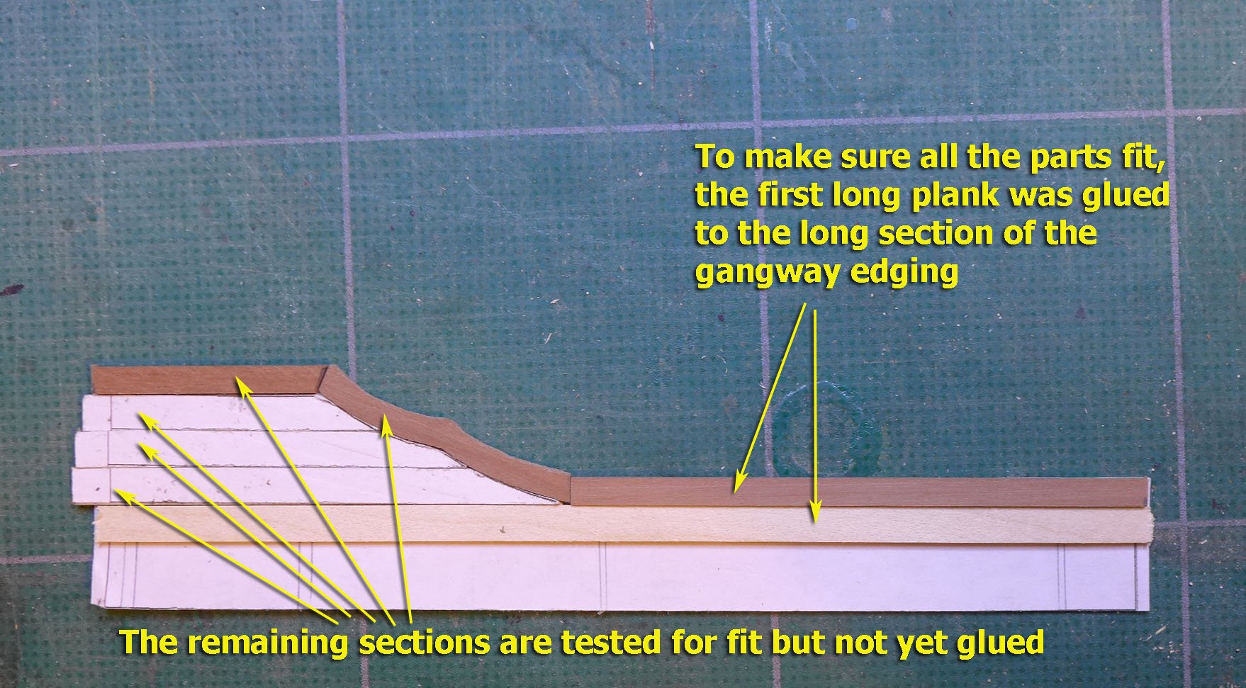
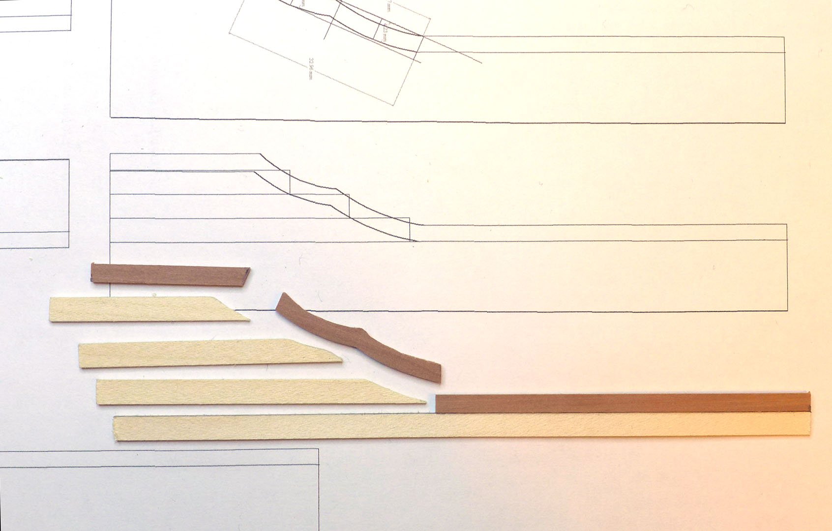
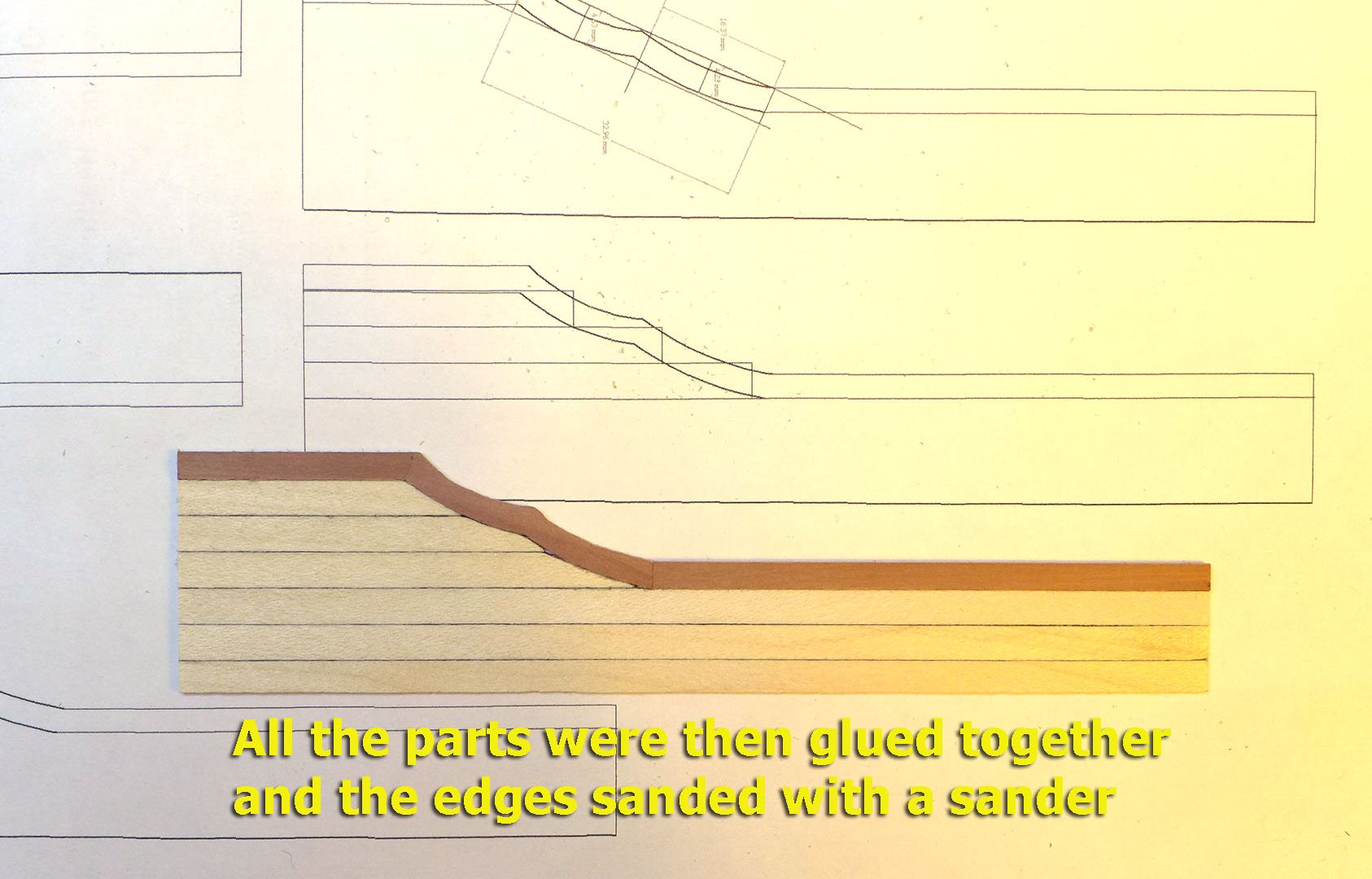
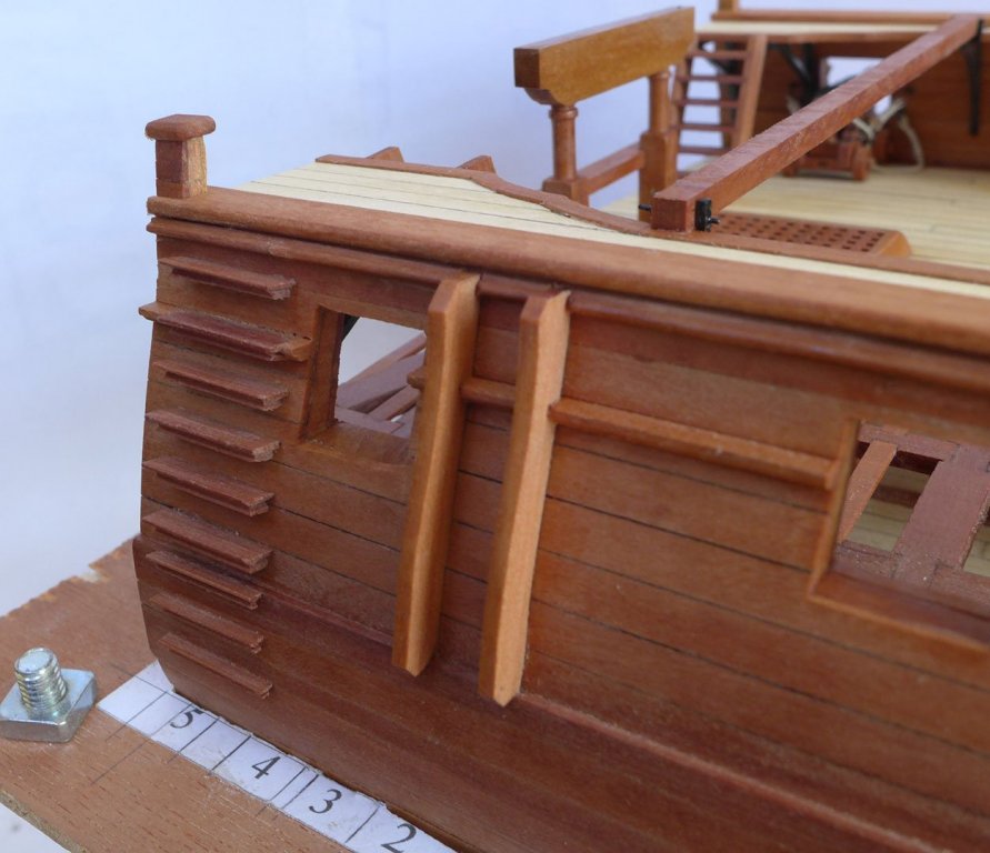
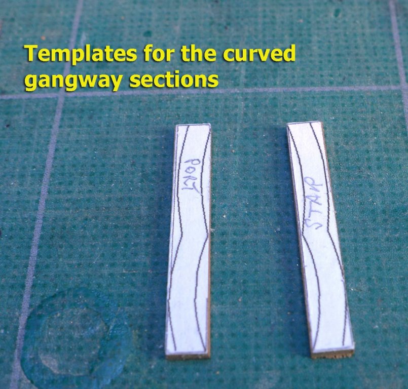
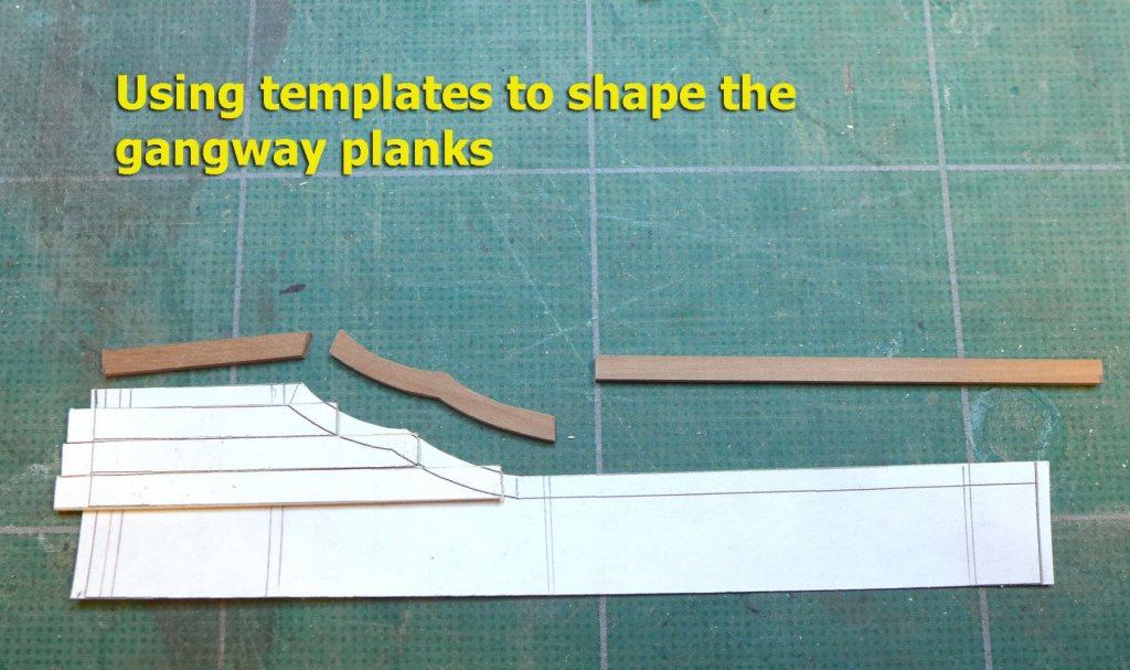
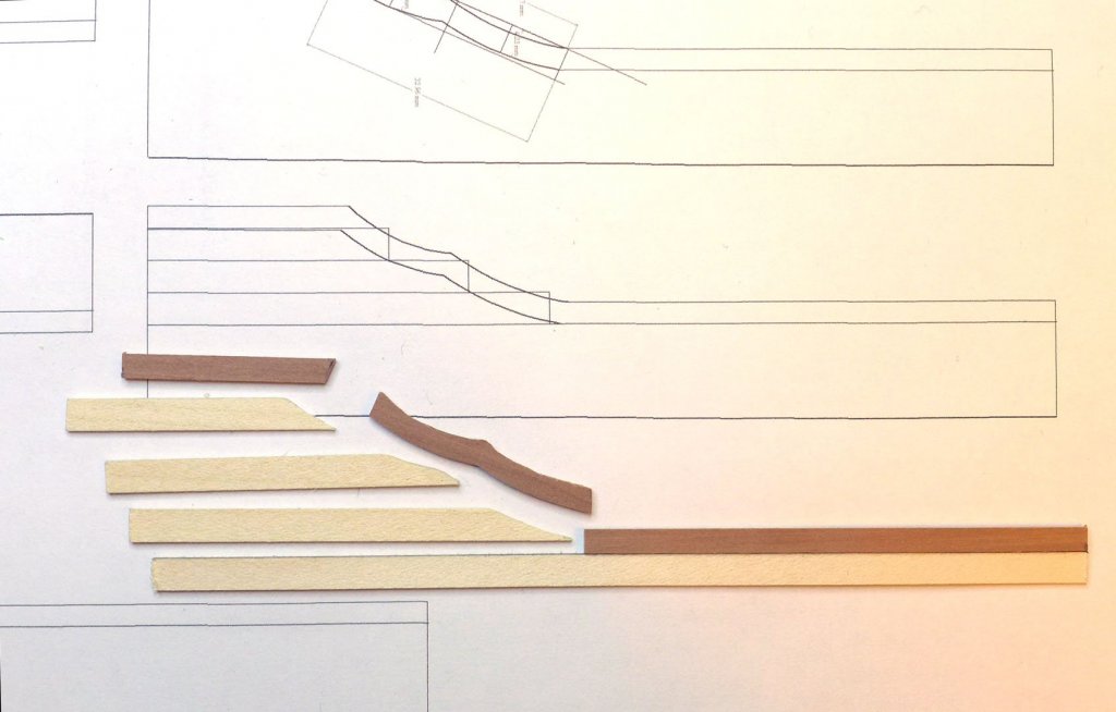
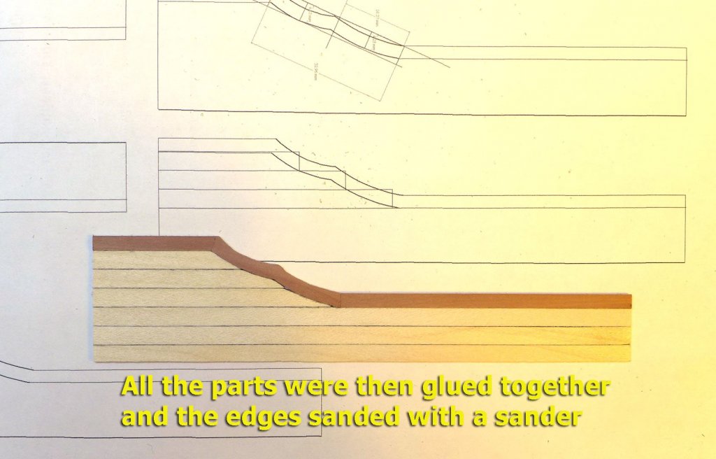
GANGWAY I thought the best way to make the gangway would be to make the entire section separately and then lay it on top of the knees. The tricky part would be to make the curved sections in the middle – which I did by making a template for these. I then used templates to shape the gangway planks The key to the structure is the first long gangway plank, which, when glued to the longer section of the gangway edge, provides the reference for the remainder of the planking and the edges. The parts were then all glued together and the edges of the gangway sanded with the Proxxon sanding machine. Tony

- 132 replies
-
- 8
-
-
- triton cross-section
- cross-section
- (and 1 more)
-
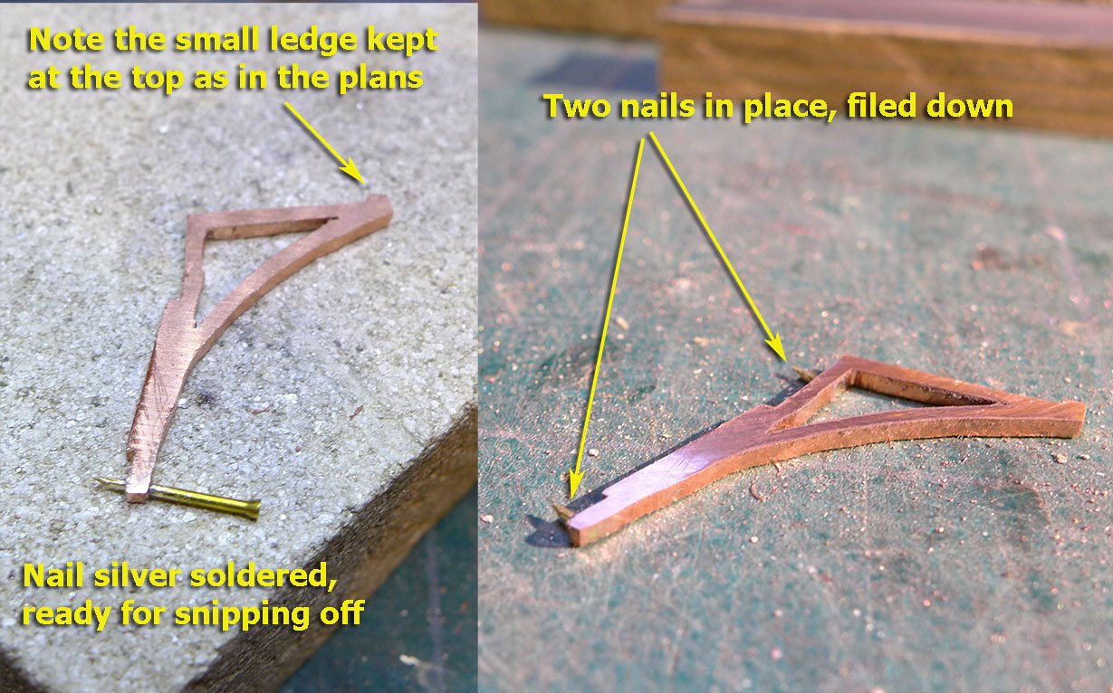
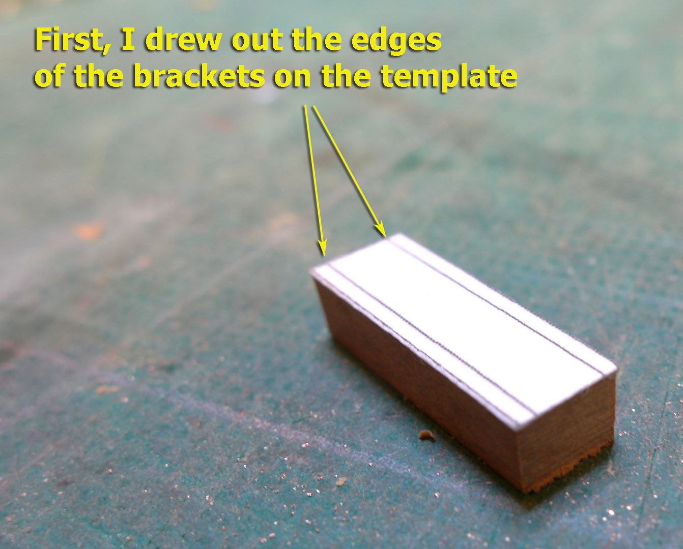
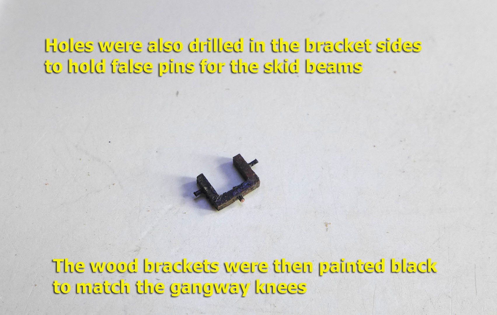
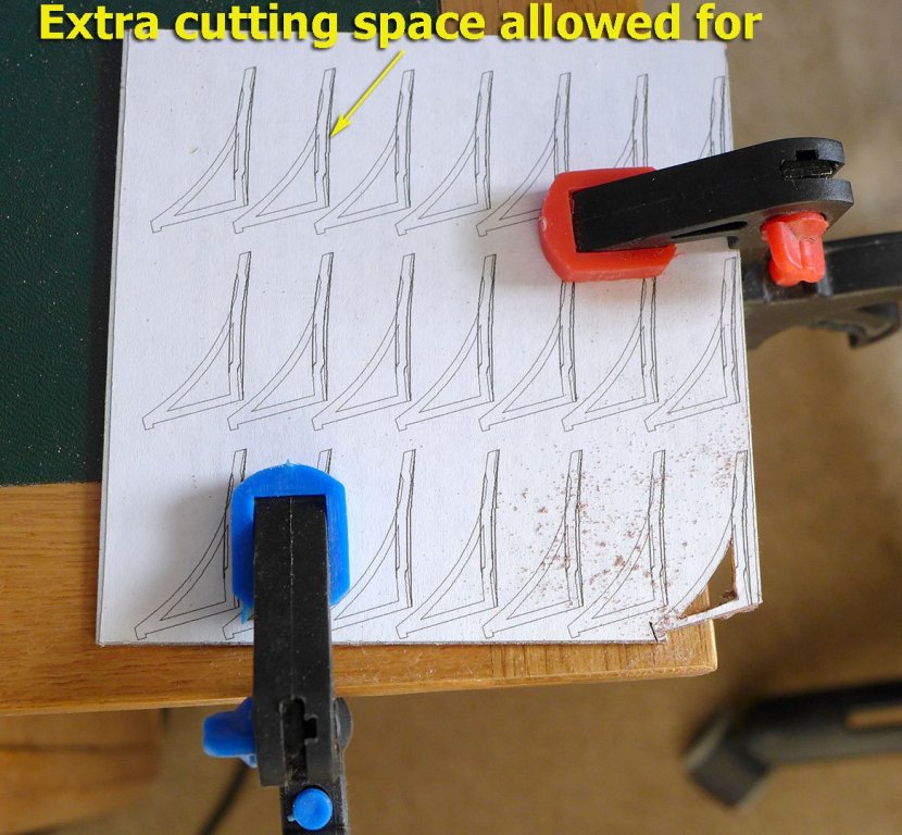
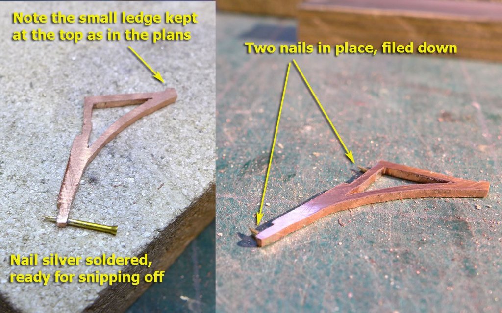
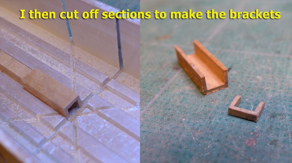
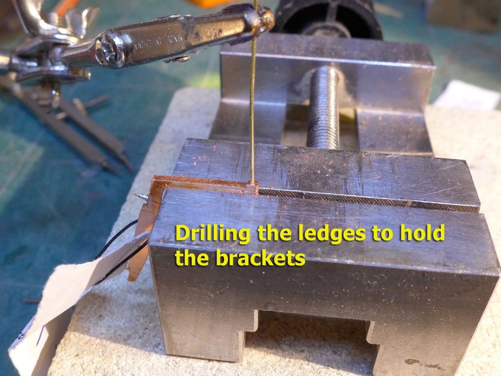
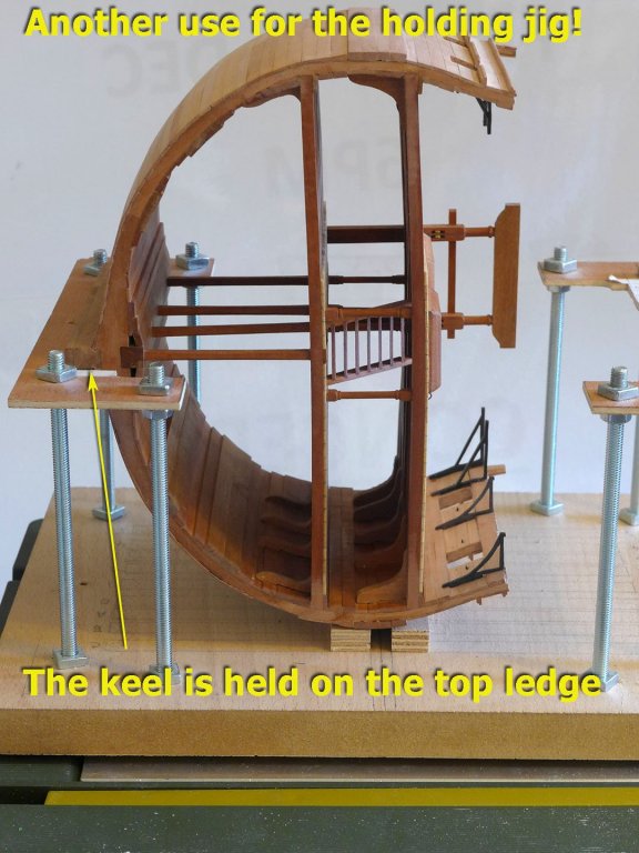
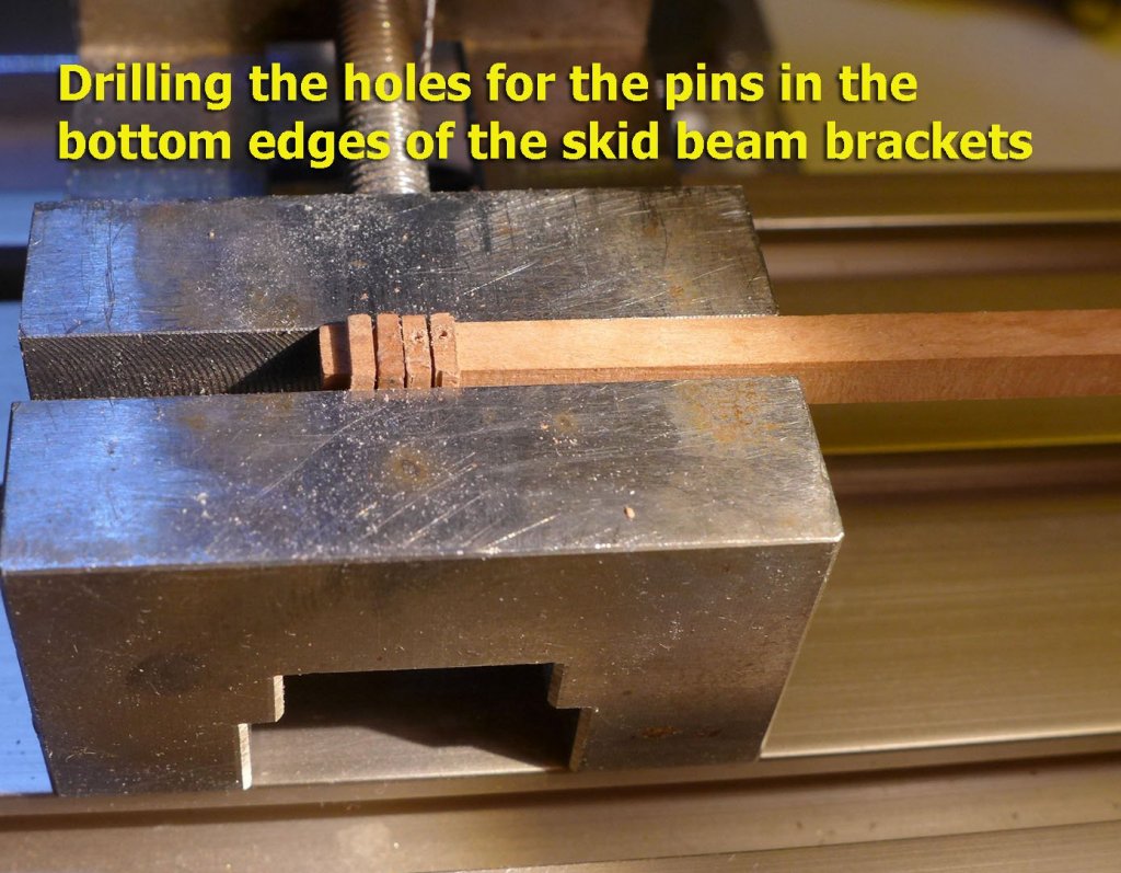
GANGWAY KNEES I bought two copper plates, 1.9mm and 1.3mm thick, so that I could use Grant’s idea [https://modelshipworld.com/index.php?/topic/492-grants-triton-complete/&do=findComment&comment=62850] of cutting the knees from plate instead of constructing them from wood or brass strip. In order to allow for differences between the plans and the build, I made extra room on the templates for the junction between knee and ceiling. I thought it would be a good idea to fix the knees with brass nails. However, later, when it came to fixing them to the ceiling, I found it easier to file them off and glue the knees with rapid epoxy. Grant decided to keep the tops of his fore knees without the small ledges to hold the brackets. I assume he did this so that it would be easier to solder on the brackets for the skid beams. However, the ledge allows for the fact that the bracket edges up to the gangway planking. At first I thought I’d drill holes in the ledges and then fix copper brackets to them with nails and solder that way. However, I then thought of another way of fixing the brackets as I thought that making the brackets with copper or brass was not at all straightforward. This involved milling out a square section of pear, as you’ll see in the following photos. When fitting the brackets, I found myself really liking the fact that I could use my holding jig to keep the section on its side. I then finished off the brackets by drilling holes in their bases to hold the pins that would tie them to the knees, drilling holes in the sides to hold false pins for the skid beams (to give the appearance that they run through the beams) and painting them black to match the knees. Next up: the gangway, entry steps and fenders. Tony


- 132 replies
-
- 6
-
-
- triton cross-section
- cross-section
- (and 1 more)
-
Aaah! You're a real sweetie, Dirk! Thanks. Tony
- 132 replies
-
- 2
-
-
- triton cross-section
- cross-section
- (and 1 more)
-
Yes, it's very satisfying to learn these skills. I was thinking this morning that there's nothing really hard about this hobby: it's more a process of trying, learning from others, learning from your own attempts, trying again until you understand your tools, understand the geometry, understand the materials, and let problems simmer until at some time you think of a solution. Intensely absorbing and challenging. Tony
- 132 replies
-
- 4
-
-
- triton cross-section
- cross-section
- (and 1 more)
-
Thanks, Jörgen, that's very nice of you. But you should have a look at some of the other Triton builds which are very much better done. All the same, these models are beautiful, and, oddly, even my wife uses that word when she sees it from time to time. Part of the reason for doing this kind of modelling is, of course, to enjoy and appreciate the beauty of these ships internally and externally. Tony
- 132 replies
-
- 3
-
-
- triton cross-section
- cross-section
- (and 1 more)
-
Very good choice! And excellent work into the bargain! Tony
-
As you'll have seen from the other Sherbourne builds, the gunports and their heights have always been a problem. Others more knowledgeable may guide you here, but I think that ideally the gunport bottom edge should follow the line of the deck and be of sufficient height so that the maximum and minimum elevations of the gun barrel are not impeded. Some have re-shaped the gunports simply by planking over the bulwark and cutting them out afresh. The ports tend to become more diamond shaped as the rake of the deck increases toward the bow. I think you'll have to work out your own particular solution. It's worth looking at the builds of Kester (Stockholm Tar), Dirk (Dubz) and Gregor, who also have a full discussion about the gunport covers. As for treenailing, they should follow the frame positions and the plank positioning which allows for correct butt placement. You'll see the frame positions (which run vertical to the keel) on the original plans -- again which you'll see on Dirk's and Gregor's build. For planking and how to position the planks, see the tutorials in the resources section on the forum. However, if you're going to paint the hull, you won't need treenailing to be shown. Tony
-
The choice re the tv is easy. There's very rarely anything of interest to see on it. And even if there is, I don't mind if I miss it. But we do have one at home. Our grandchildren watch it in small doses, and in fact I think TV for kids now plays the same role for the imagination as comics used to do for me when I was a kid. But as for me, I haven't read a comic since childhood. Tony
-
Life must come first, Jörgen! It certainly does with me. Like this morning, preparing for a pleasant day with the Triton, but suddenly asked to take care of grandchildren. It's no contest! Tony
-
Nice to hear you're back on the Sherbourne, Jörgen , while you have a respite from Vasa fever. Looking forward to the descriptions of progress! Tony
-
Congratulations, Sjors! It's been wonderful to see the progress over the years, and wonderful to see such a beautiful result at the end. Tony
- 1,616 replies
-
- 5
-
-
- caldercraft
- agamemnon
- (and 1 more)
-
Do you have a picture of it? Tony
-
ancre Le Rochefort 1787 by Niklas - 1:36
tkay11 replied to Niklas's topic in - Build logs for subjects built 1751 - 1800
Very neat work! Tony -
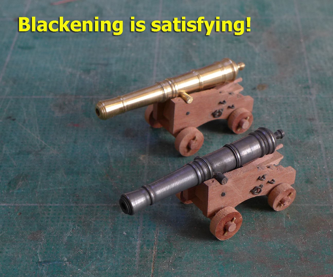
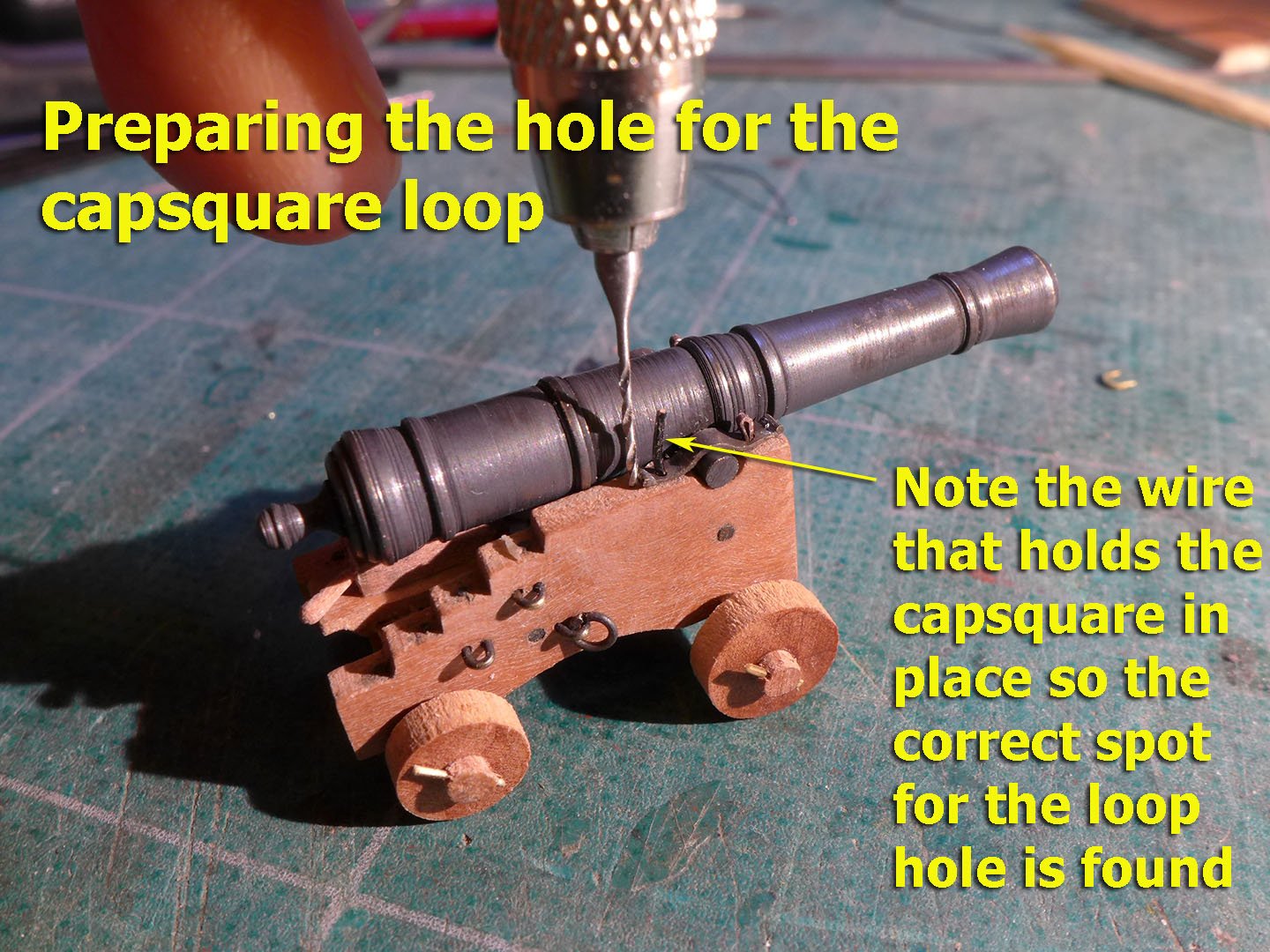
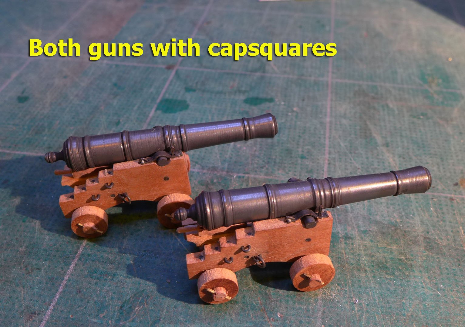
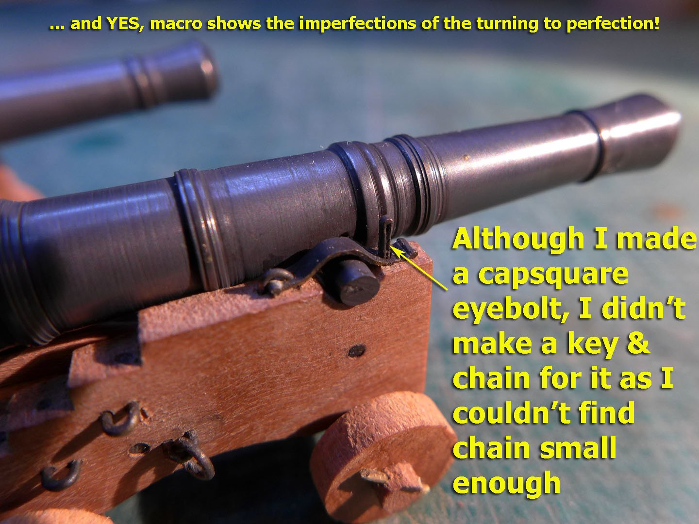
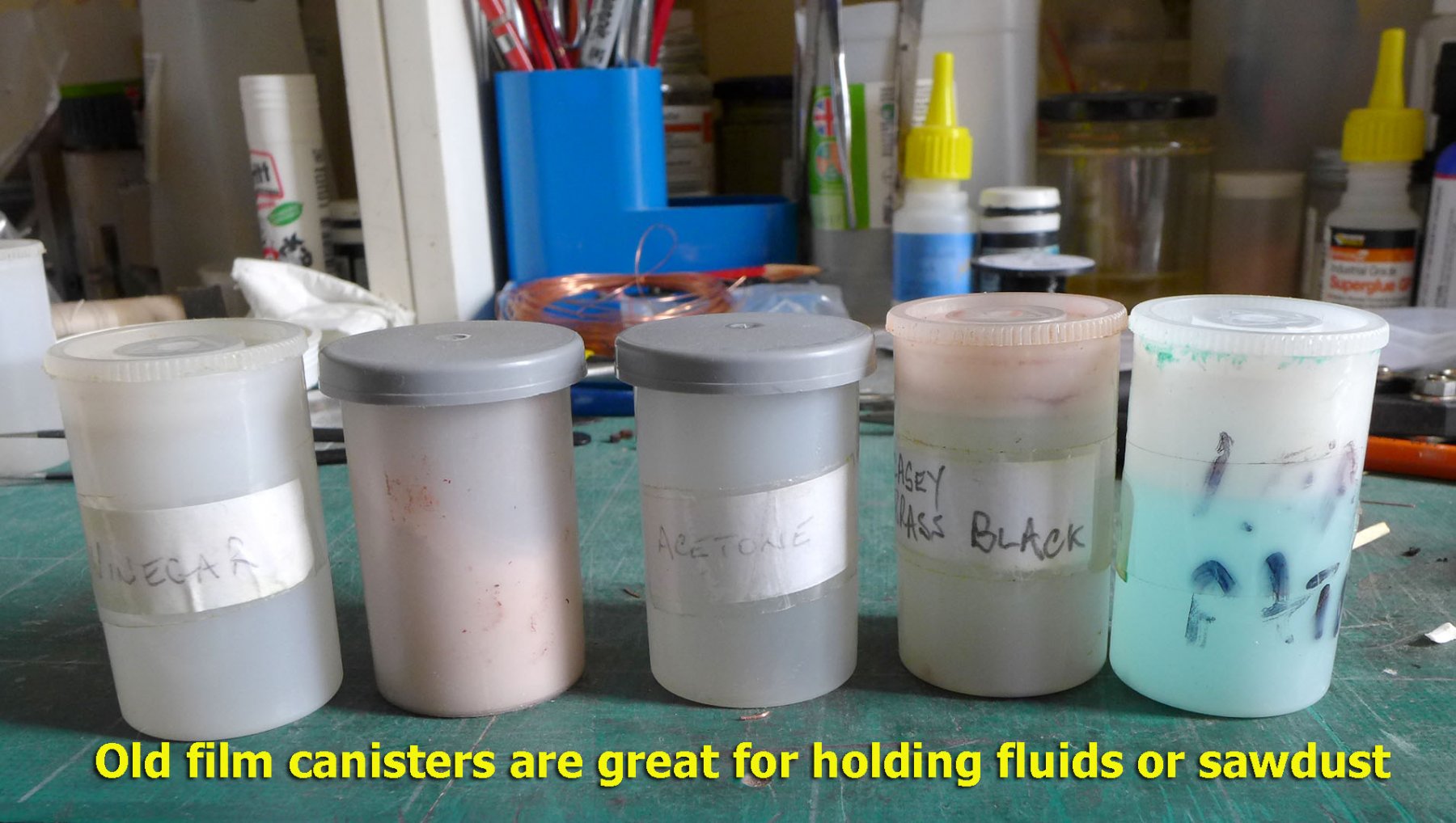
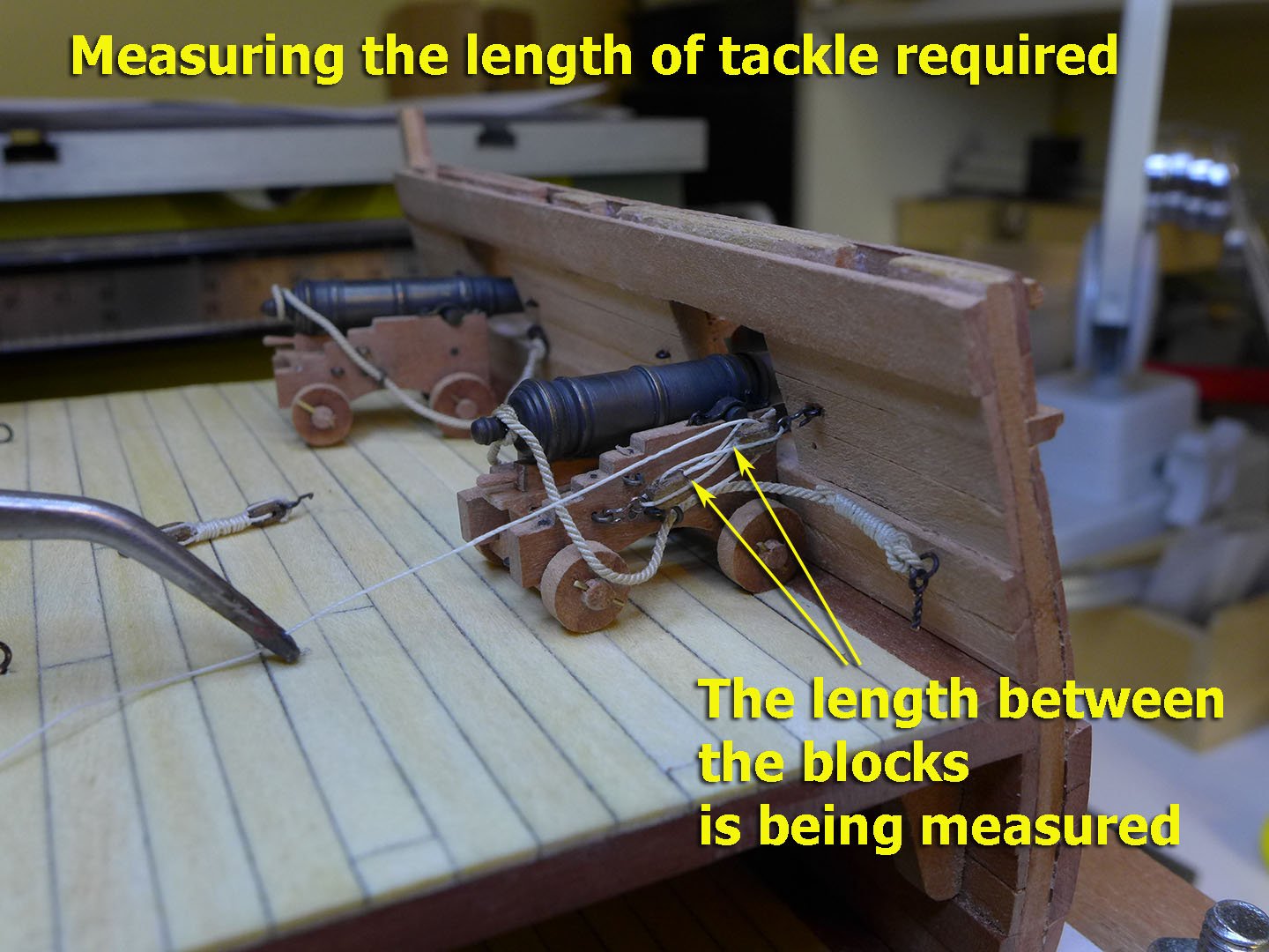
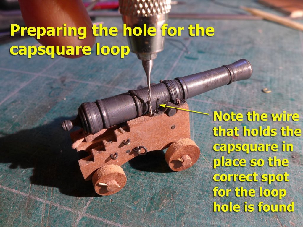
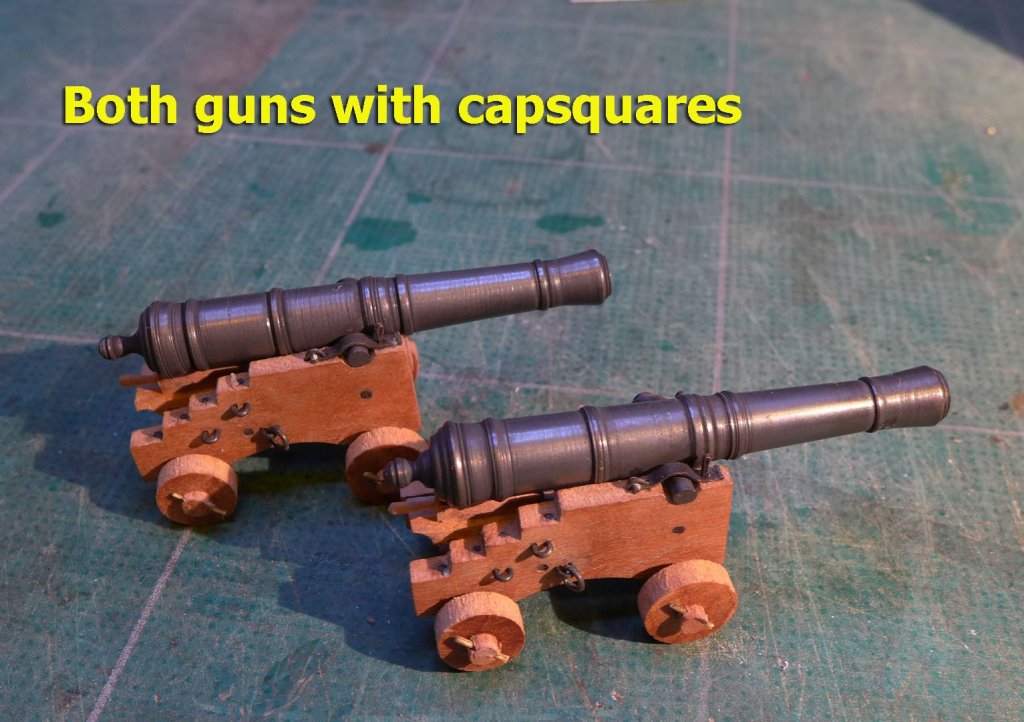
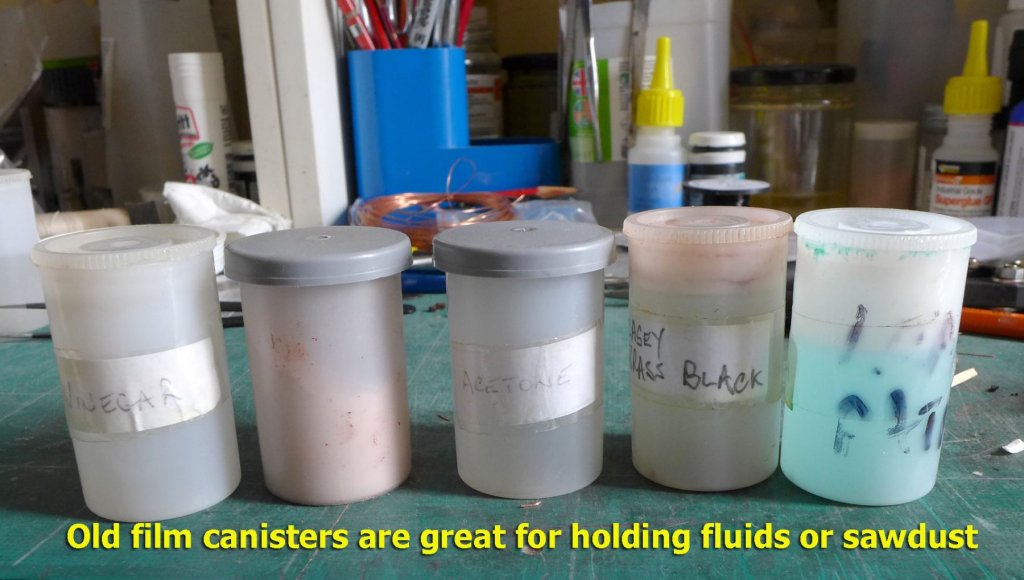
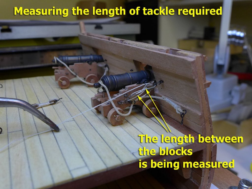
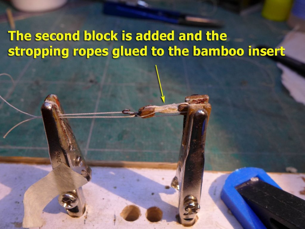
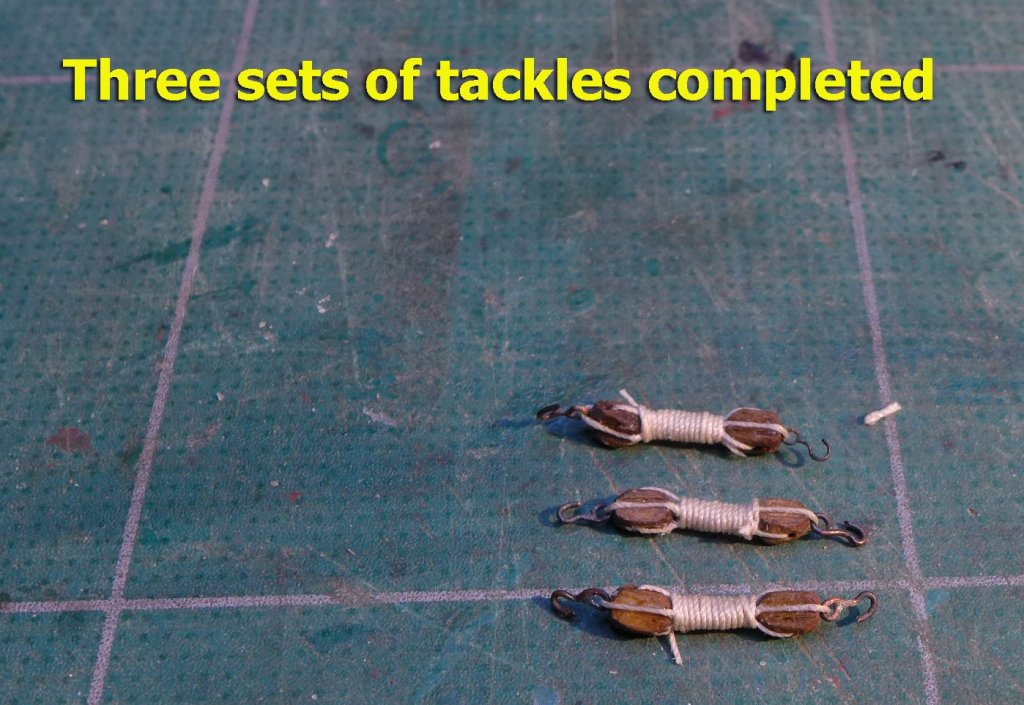
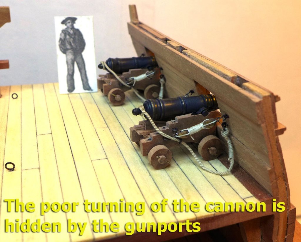
THE GUNS AND THEIR RIGGING I’m still not ready to show what I’ve done with the gangway knees, as I need to finish talking about the guns. First, the turning and the blackening. I haven’t quite achieved the level of finish others seem to manage, but for now I’m reasonably happy, and won’t be doing any more until I do another model. As an aside, I should mention that lots of photographic stores still receive film for processing. My local photo shop has lots of film canisters that they just throw away. So I go down from time to time to collect a handful. They’re great for fluids and sawdust (which I use for filler). I was even able to blacken my guns in film canisters as they are just the right size. Preparing the capsquares was fun. I have already shown the initial preparation of the capsquares in the previous posting. Here I show how I managed to place the rearmost loop. Although I made a capsquare eyebolt, I couldn’t find chain small enough to make the key with its chain. Perhaps I’ll do that another time. “IT IS FUTILE TO DO WITH MORE THINGS THAT WHICH CAN BE DONE WITH FEWER” I reckon William of Ockham (the one born in 1287) must have been a ship modeller, because the phrase above was one he used. He was following many others (probably also ship modellers) who used the same idea in a variety of guises. The reason I remembered this phrase was when I came to prepare the gun tackles. At first I used a variety of strops and thimbles, rigging them fully, but every time when it came to frapping them for stowage the result was lumpy. I eventually, and step by step, reduced the rigging by dropping the thimbles, then dropping the pieces that wouldn’t be seen after frapping. Having decided that, the first thing to do was to find out how far apart the blocks for each tackle should be. This involved rigging the guns in a rough fashion to their loops in the hull and drawing them tightly to the sides. In order that the frapping should be as smooth as possible, I then stripped a piece of bamboo through a drawplate till it was 1mm diameter and glued it between the shortened stropping ropes. The second block was then added and the ropes glued to the bamboo strip. I could then rig the guns to the bulwarks. You’ll note that luckily for me the deficiencies in my turning of the cannon are well hidden by the gunports! So I’ll now be continuing with the gangway knees. Tony


- 132 replies
-
- 14
-
-
- triton cross-section
- cross-section
- (and 1 more)
-
I was at Balliol. My daughter was at Queen's, though. Tony
-
Wonderful to see your work here again! Thanks for the update! Tony
- 121 replies
-
- 2
-
-
- la jacinthe
- schooner
- (and 2 more)
-
Gosh! That was fast! Congratulations. Very nice too! Tony
-
Thanks again for more 'likes'! Gregor: Nice to hear from you. How's the modelling coming along, i.e. Irene, Jacinthe? I've just bought the Petrejus book about the brig Irene on eBay and waiting to see it. Tony
- 132 replies
-
- 3
-
-
- triton cross-section
- cross-section
- (and 1 more)
-
Just want to add my congratulations, BE. Let's hope this is now permanent! Tony
- 366 replies
-
- 3
-
-
- pegasus
- victory models
- (and 2 more)
-
Kenny, very nice progress! I just want to say that it really is worth while learning how to do silver soldering. The equipment is not at all expensive. You just need a simple small pencil torch (about UK£4.50 or less on Amazon now). I bought one of the model I've linked to 4 years ago and it's still going strong. If you buy the larger ones with press button ignition you may well find they're less reliable (I did). Then you need a syringe of soft silver solder paste (I bought mine at the same time for about UK£9 from cupalloys and that too is still going strong). That's the total extra expenditure. I'm sure the prices will be similar or less in the USA. There's a tutorial on the site which tells you exactly how to do it. You'll find that there's a great deal that can be done with this. Also, if you don't want to make the gangway knees with silver soldering, you can also cut out the shapes from copper plate as was done by Grant in his Triton build. I've just done them that way, although nowhere near as nicely. Tony
-
That's very nice of you Pete. But your own build seems to be getting along just beautifully and, dare I say it, much neater than mine! Tony
- 132 replies
-
- 3
-
-
- triton cross-section
- cross-section
- (and 1 more)
-
That's really strange! I have just sent you a personal message asking about the dutch books you mentioned in your build log of the Ostend Shrimper! Thanks a lot for the suggestion. I've just looked online and reserved it from my library! Tony
- 132 replies
-
- 2
-
-
- triton cross-section
- cross-section
- (and 1 more)
-
Thanks very much for the nice comments and likes! It's a joy to receive encouragement from peers who really understand the difficulties, intricacies and mistakes of this hobby and who've all been through the same learning experience. G.L.: You made me laugh out loud when you say 'masterpiece'. I keep trying to explain and show in detail every point at which it clearly is far from being at all masterly (so others can learn from my mistakes), but your comment did make me go to have a look at your Oostends schipje and I can say with full confidence your skills far outweigh my own. I'll be following that with great interest from now on as I have the plans for the Brixham trawler Valerian and I want to build that plank-on-frame. I have not yet found any source giving the framing patterns for those trawlers, so the details you have about the framing on a similar kind of boat are of great use for me. I also admire your drawing and lofting skills -- it's all made too easy nowadays with computer programming with the downside that we lose the thinking behind the drafting skills. Tony
- 132 replies
-
- 2
-
-
- triton cross-section
- cross-section
- (and 1 more)
-
I have just listed my copy of George Bandurek's book "Super-Detailing the Cutter Sherbourne" on eBay in the UK. It's as 'Buy it Now or Best Offer'. If anyone is interested the link is http://www.ebay.co.uk/itm/-/112326241142? I'll let it run on 30-day cycles until it's sold. Tony