DONATION DRIVE - SUPPORT MSW - DO YOUR PART TO KEEP THIS GREAT FORUM GOING!
×


tkay11
-
Posts
1,829 -
Joined
-
Last visited
Content Type
Profiles
Forums
Gallery
Events
Everything posted by tkay11
-

Mini Mill recommendations
tkay11 replied to StebbinsTim's topic in Modeling tools and Workshop Equipment
Very helpful comment, John. Thanks. Tony -
Mini Mill recommendations
tkay11 replied to StebbinsTim's topic in Modeling tools and Workshop Equipment
I don't have any mill (apart from my modified one) and always pop my head in whenever there's a discussion about mills just to see what's changed over the years. I found the comment by jhearl very interesting bur very hard to assess because in Europe the Proxxon small mill, as has been said, is very popular indeed and used by many master modellers with much expressed satisfaction and the results are there to be displayed on their many web pages. We've also had so many discussions through the years of how the small Proxxon is the only one to offer the ideal high milling speeds for very small cutters or mills in wood -- whilst not being at all useful for metal. There is also a following for the more powerful Proxxon mill/drill set up round the BFW 40/E which similarly has very strong advocates -- certainly by many of the French modellers and by those who want to mill some metal. Then again I hear modellers who use the Chinese-made mills advocating their own brands powerfully. It certainly is confusing to try to choose when presented with this plethora of voices. I suppose it might be a case of people learning the limitations of their tools, no matter how costly or complicated, and finding ways to work with the limitations and their particular needs, then singing the praises of the tool rather than their skill. One day I hope to be able to have enough money to take the plunge and buy one but for the moment I'm still learning how to use chisels and planes. Now there's another set of tools that have voices all over the web decrying or praising particular brands. Tony -
Thanks, Guy. I don't think I'll need to adjust for camber at the base as the gratings will fit into the coamings. On the upper surface I'll likely be sanding against a curve. I have the inside of an old cake tin that seems to have the camber needed, but if not I'll probably cut and sand a surface down and lay some sandpaper on it. It's a long way before I reach that though, so I've time to think about it. What would you suggest? By the way, how are you getting on with the full build? Tony
- 132 replies
-
- 3
-

-
- triton cross-section
- cross-section
- (and 1 more)
-
That's really great, Ed. Thanks a lot! I've only built one kit (Sherbourne) and am moving through the Triton Cross-Section -- which I'm enjoying immensely. I'm really tempted to move on to the Naiad after the cross-section, but fear it may be too much to take on without more experience so I may buy the books at least to gain an insight into the techniques used and try to decide whether I need to postpone taking it on and build other fully framed models before doing so. Thanks also for the wonderful build logs you have made and continue to make! Tony
-
Is there a table of contents available for Volume II? Sorry if I missed it but I'm interested in buying the set and just wanted to check out what additional info is provided in the second volume. Thanks Tony
-
Also, in case you don't know about it, there's George Bandurek's book on Super-Detailing the Cutter Sherbourne, which is a much more detailed explanation of his build log with lots of pictures. I may well put mine on eBay and if so, I'll let you know. Tony
- 25 replies
-
- 1
-
-
- finished
- sherbourne
- (and 1 more)
-
I don't know if you've seen Lennarth Petersson's book on Rigging Period Fore-and-Aft Craft, but it provides and excellent guide to a cutter's rigging with very simple drawings. It was invaluable for me as I had no understanding at all about rigging and it seemed a totally mysterious and complex art before I started. If you're good with search engines you might even find it as a downloadable pdf. Otherwise it's not expensive to buy -- especially if you buy a used copy. You can even buy a Kindle edition from Amazon at https://www.amazon.co.uk/Rigging-Period-Fore-Aft-Craft/dp/1848322186. It has a couple of very small errors, but these are pointed out in the build logs. If you do go for more complex rigging, there are some interesting discussions about where to place the belaying points around the bowsprit. Be wary also of whether you're going to position the top mast fore or aft of the main mast. The kit and a lot of people have it going aft, but there are good arguments for it going forward. I went with Petersson and had it forward as it fitted with a lot (not all) contemporary models and it gives good strength to the support of the gaff. In the end it's a matter of opinion, and if you go aft the kit does provide the parts to do that -- going fore means you have to make your own parts. It's a good idea whilst you're looking at the other logs to keep these points in mind and see how others have approached the issues. Tony
- 25 replies
-
- 1
-
-
- finished
- sherbourne
- (and 1 more)
-
Nice progress, Rob. It might be worth thinking about how much rigging you'll be doing. If you're going to go for more than the kit plans, then now might be a good time to think about belaying points. Quite a few of the Sherbourne builders add more belaying points here and there. Of course this won't be an issue if you're sticking with the kit plans. Tony
- 25 replies
-
- 1
-
-
- finished
- sherbourne
- (and 1 more)
-
Mapping pins or drawing pins with an edge worked quite well for me when keeping wood flat whilst bending. Tony
-
Thanks, Christian. I'm much enjoying your Fly -- as well as learning from the build. Tony
- 132 replies
-
- 2
-
-
- triton cross-section
- cross-section
- (and 1 more)
-
Thanks for the comments and likes! I'm beginning to get a hang of the rhythms and the requirements for accuracy of cutting and thinking in the various dimensions. It certainly is a very engrossing and rewarding to be building just from plans, and to keep developing new skills as we go along. Another facet that is interesting is the increased focus on good use of basic hand tools -- saw, scalpel, chisel, scraper, file, compass, ruler, dividers, pencil, sanding stick -- and I really appreciate learning about them. Tony
- 132 replies
-
- 4
-
-
- triton cross-section
- cross-section
- (and 1 more)
-
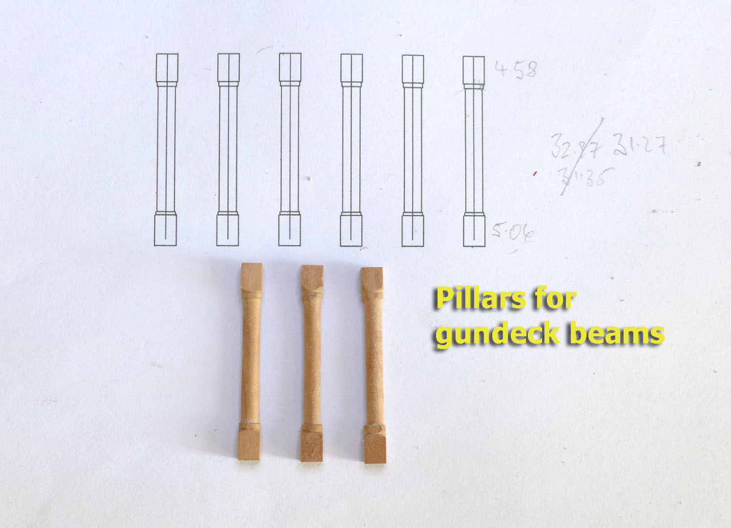
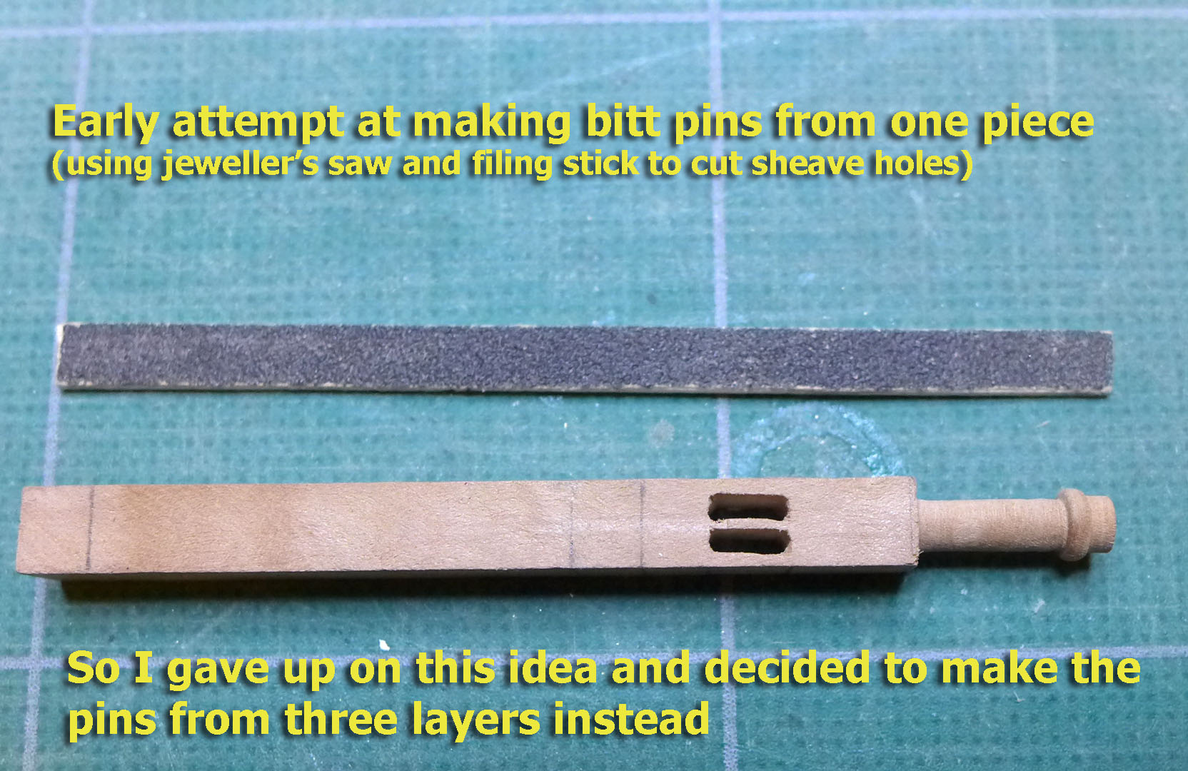
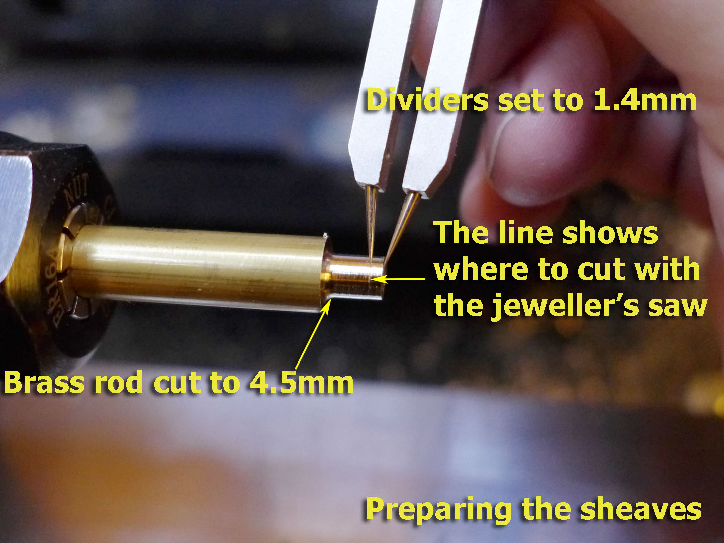
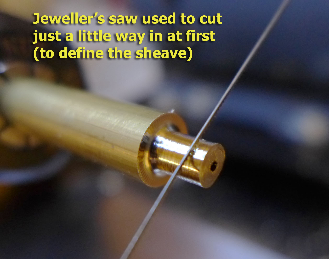
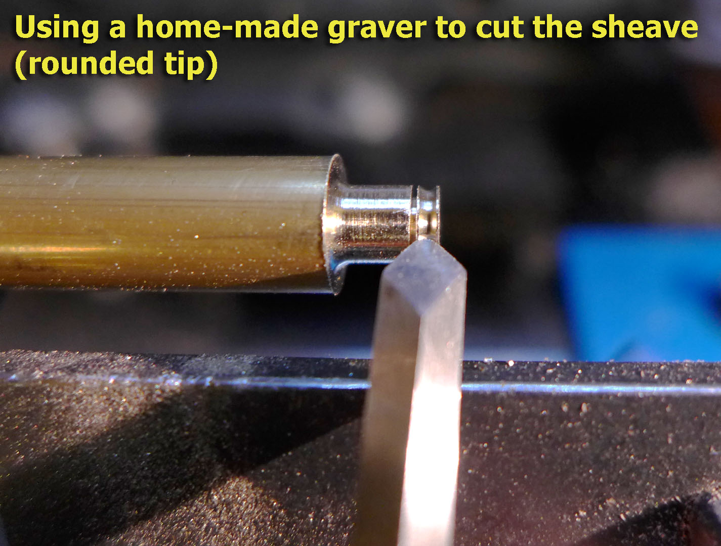
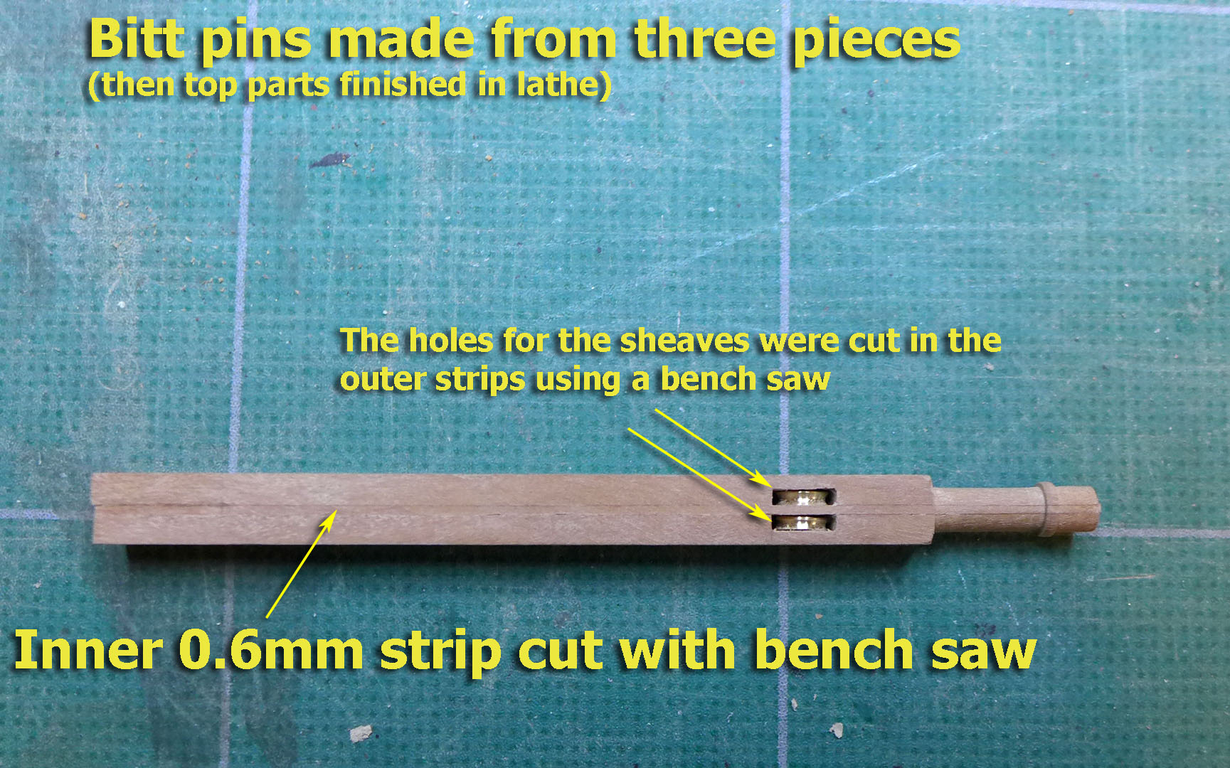
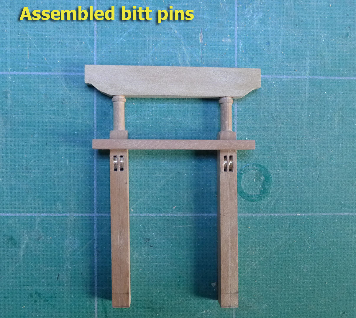
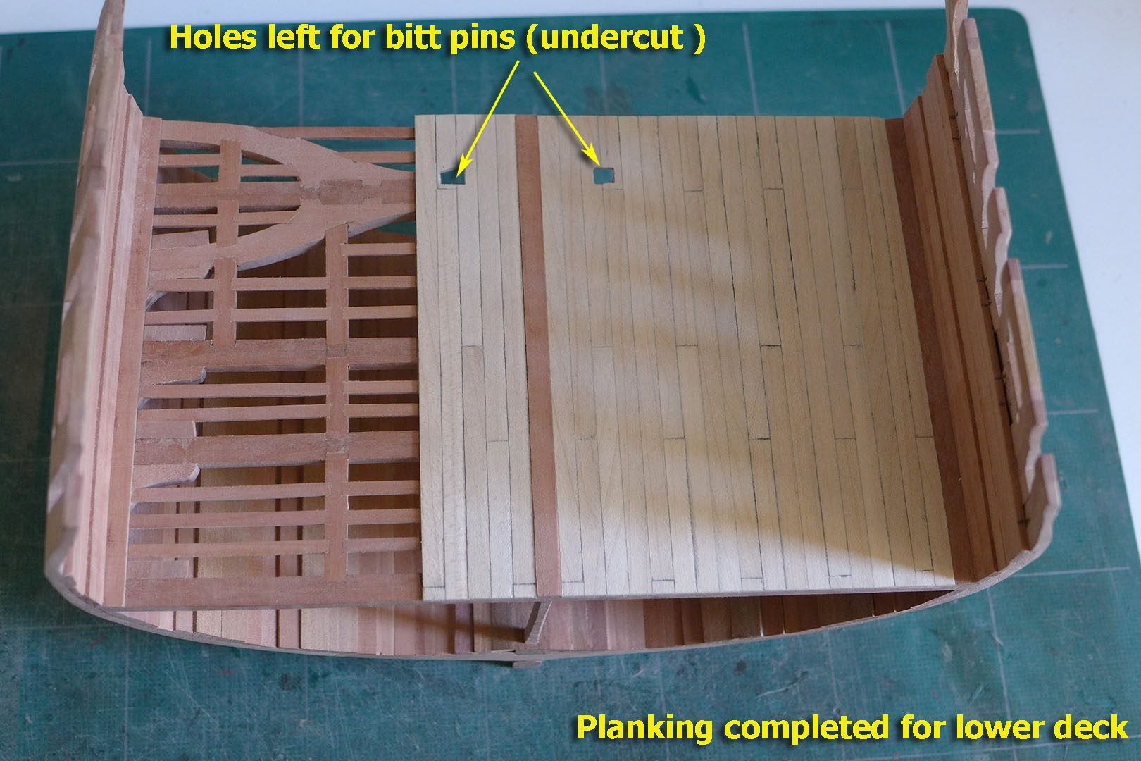
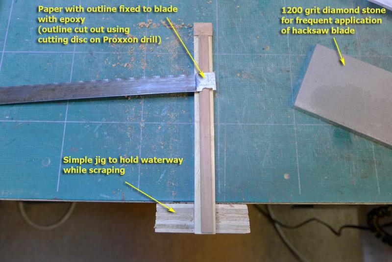
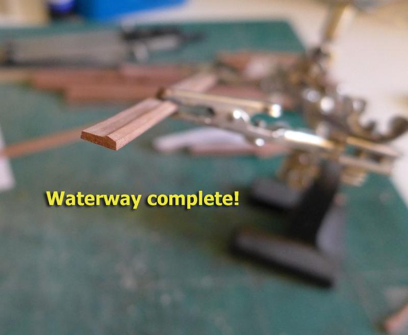
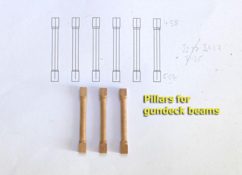
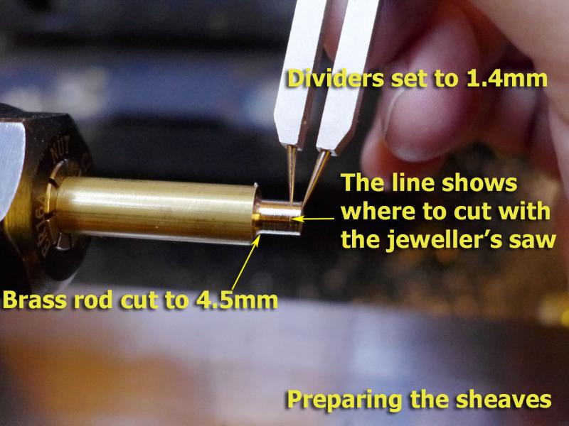
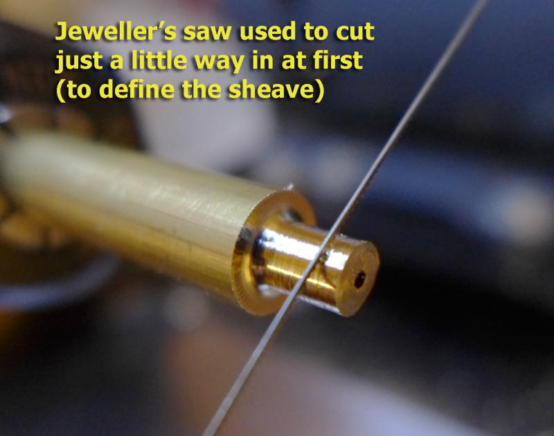
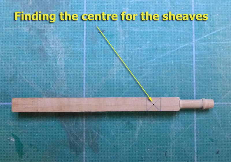
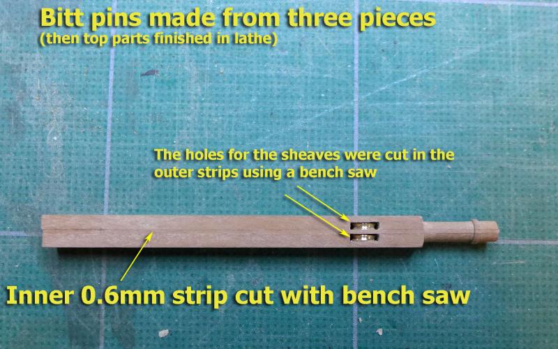
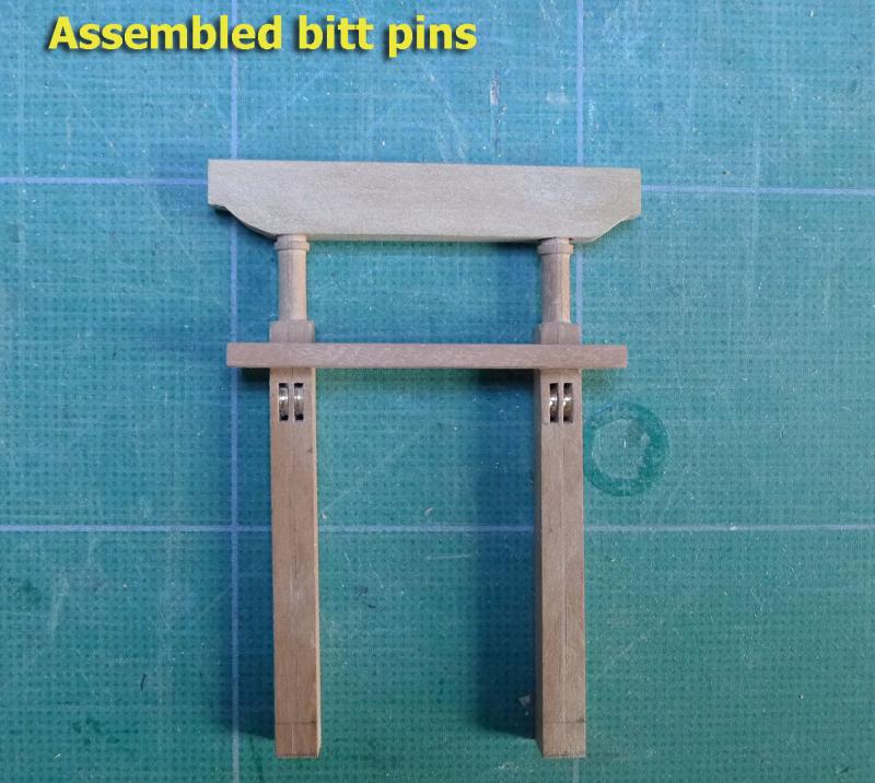
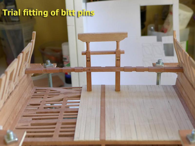
GUN DECK WATERWAYS Having thought about the gun deck waterways I realised I just had to learn how to make and use a scraper as the shape was too complex for the simple use of a saw as I had done previously for the lower deck So I made my scraper and found that it was not that hard to use – especially if I kept the old hacksaw blade edges really sharp by frequent rubbing on the diamond stone. PILLARS FOR GUN DECK BEAMS These were shaped on the lathe as before. I am only using three pillars, and decided to leave off pillars on either side of the steps. BITT PINS I first attempted to make these from single blocks of wood, but found that cutting the sheaves using a jeweller’s saw was too inaccurate. In addition, the mill bits I have are too short to go the full length. So I went the route of making them from three strips, with the central slice cut very simply with the desktop Proxxon saw. The sheave holes were then cut in the outer strips again using the bench saw. The sheaves themselves were cut in brass rod using one of my home-made gravers. I used dividers to establish the width of the sheave, then a jeweller’s saw to define the outer extent. After then cutting the groove in the sheave it was a simple matter to cut the sheave off the bar using the jeweller’s saw. Next up: putting together the beams, carlings, ledges etc for the gun deck. Tony


- 132 replies
-
- 17
-
-
- triton cross-section
- cross-section
- (and 1 more)
-
Great feeling, isn't it, as it grows more and more like a ship! Nice progress. Tony
- 25 replies
-
- 1
-
-
- finished
- sherbourne
- (and 1 more)
-
Great to have another cutter on the block. Looking forward to your build. As you've seen, there are lots of builds you can refer to. The Sherbourne is very similar to the Lady Nelson in construction, so have a look at Gregor's, Dubz's and Stockholm Tar's builds for some really fine work and hints. I learnt a lot from them, as well as from very many other builds on this forum. Tony
-
Thanks, Eamonn. What was more interesting is that due to some unknown nautical connection of the owners of the racecourse, or even perhaps simply because of the connection with saddles, the USA Camptown races came to be known as Doo-dah days. Delighted to tickle the Irish love of the arcane and often lost treasures of true knowledge. Tony
- 1,039 replies
-
- 2
-
-
- ballahoo
- caldercraft
- (and 2 more)
-
According to Herr Stiffl in his book "Phledersroppimbanken" in the 2nd edition of 1348 I believe he called it a Doodah although it was unclear which language he was writing in at the time. It was later taken up in the phrase 'dead as a Doodah'. Tony
- 1,039 replies
-
- 2
-
-
- ballahoo
- caldercraft
- (and 2 more)
-
Thanks, Mark (and Carl and G.L. for the like). I really am conscious that making mistakes now and learning how to deal with them is laying up a nice hoard of experience for future builds. The trouble for the method for the waterway is that it will only work for a near straight run, as on the cross-section. For long curved runs round the full length of a ship I suppose I'd have to go the scraper way, and I have yet to learn how to do that. I might well practise the scraper method for the gun deck waterway. Tony
- 132 replies
-
- 4
-
-
- triton cross-section
- cross-section
- (and 1 more)
-
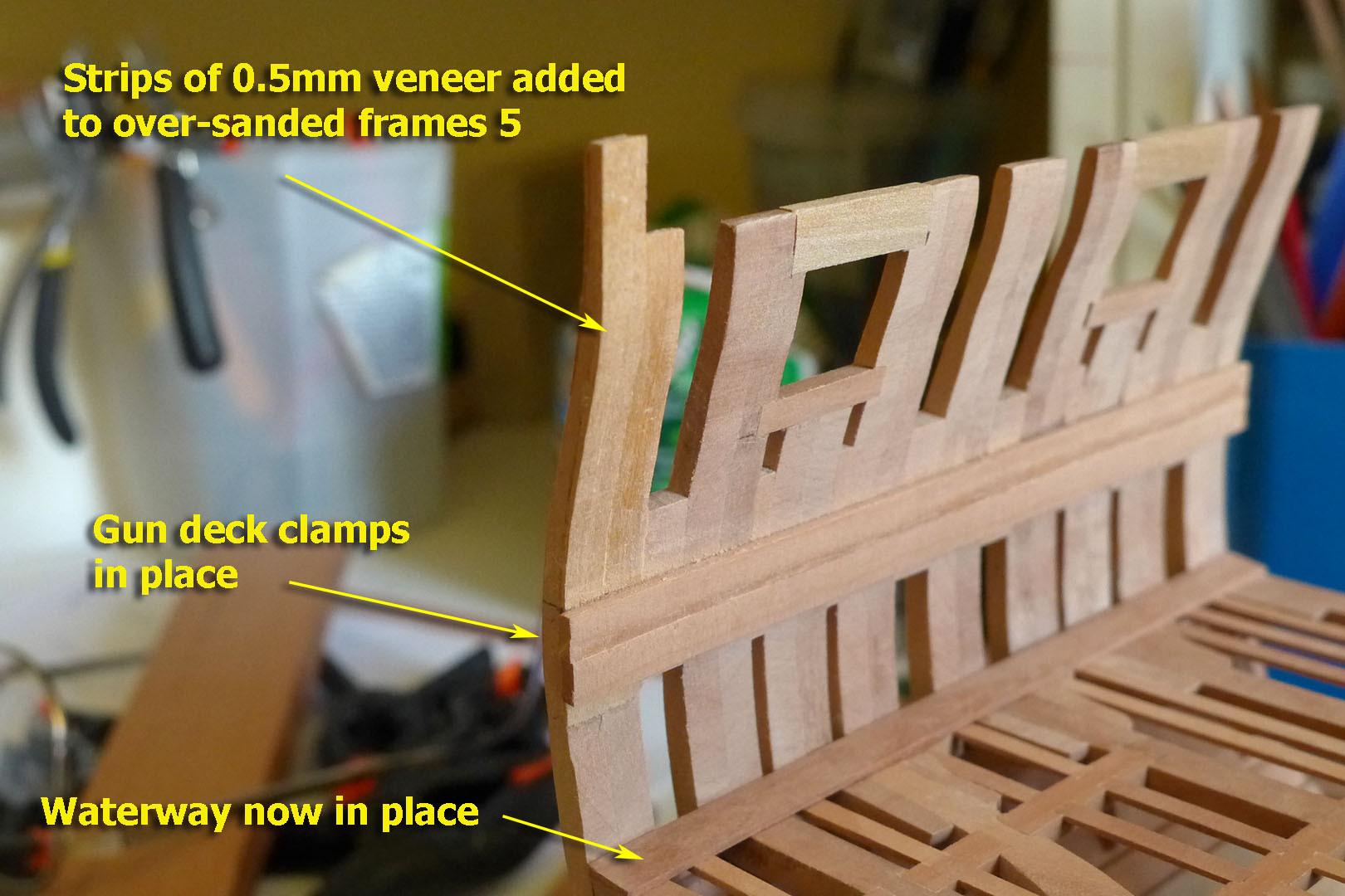
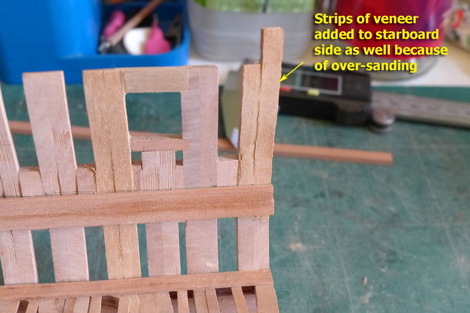
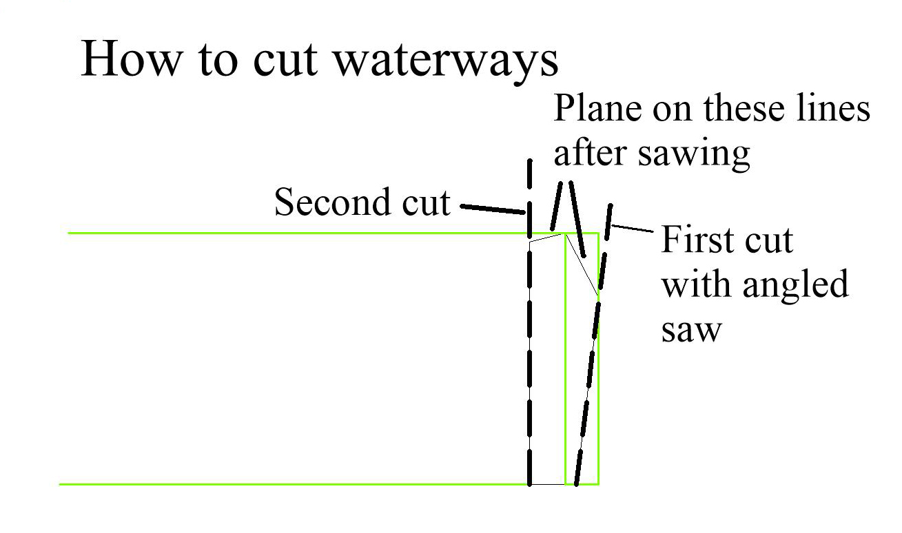
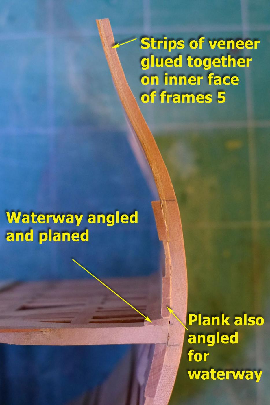
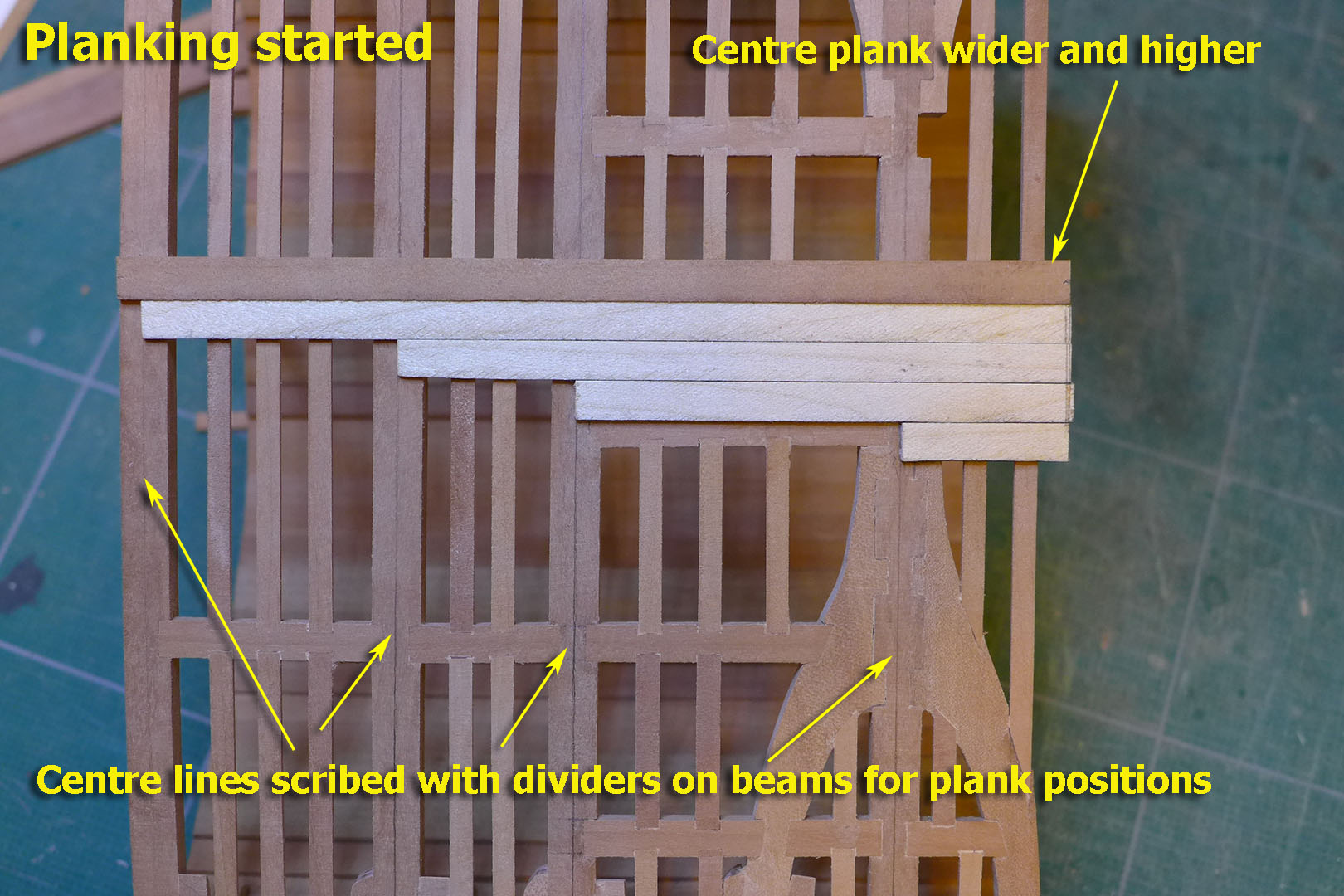
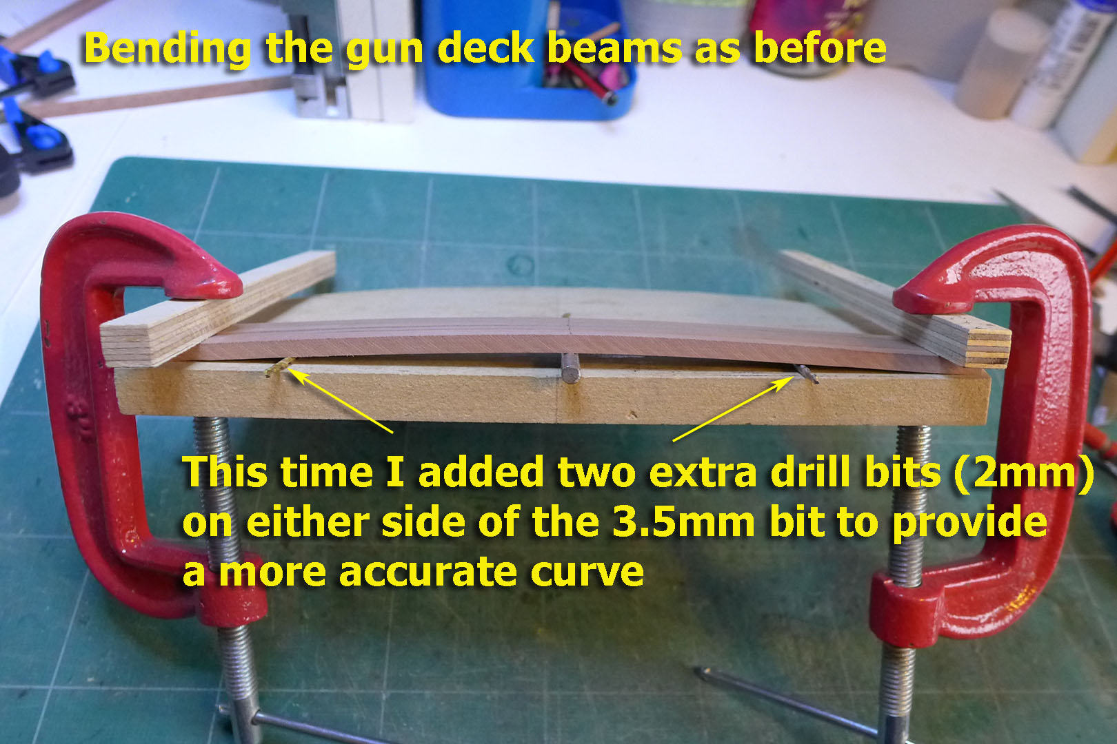
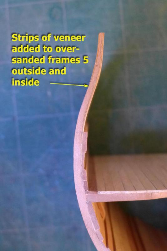
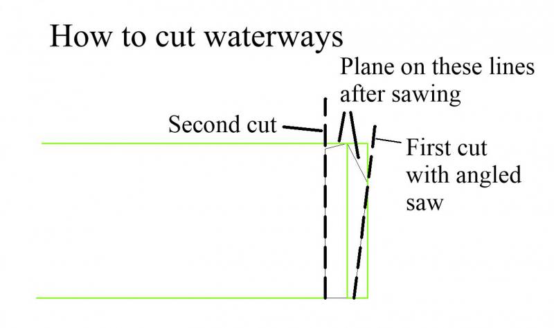
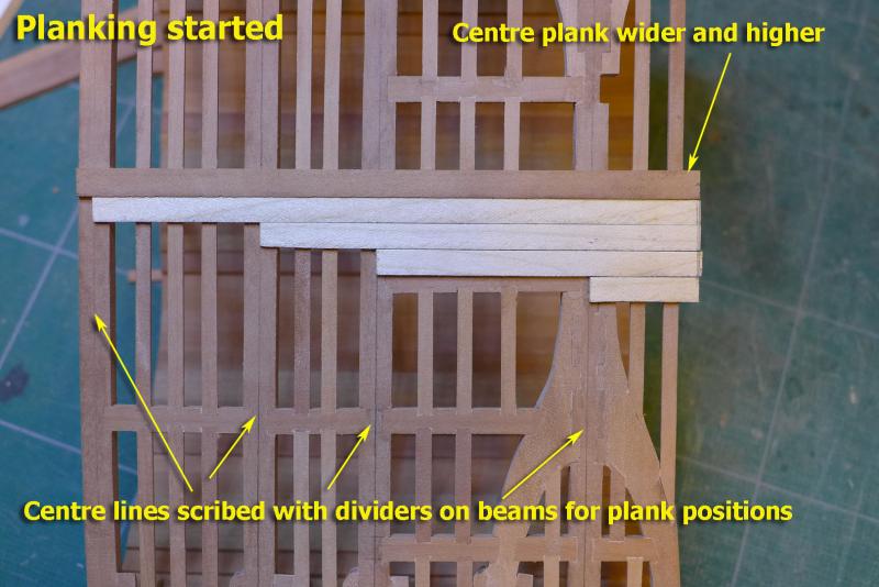
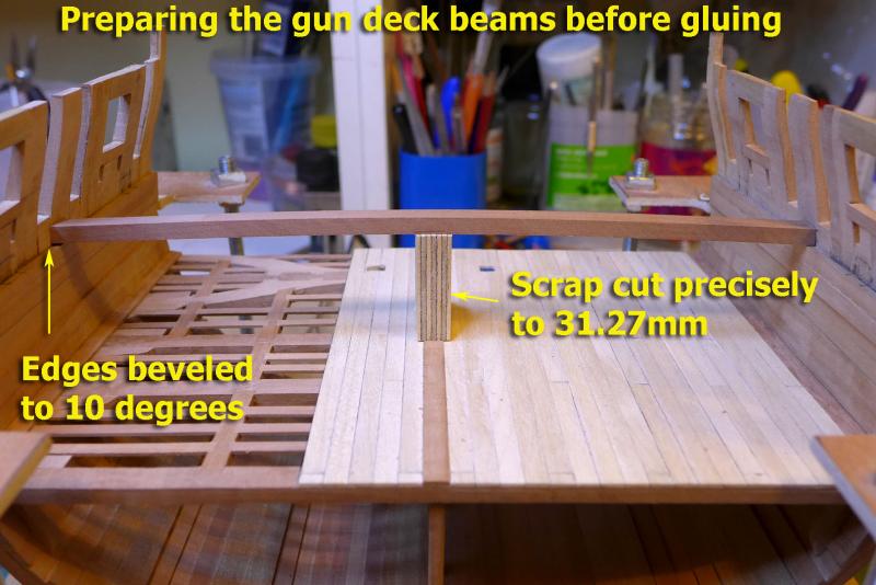
Fixing my mistakes I’m really glad I didn’t start all over again after finding I had over sanded the frames 5. It gave me an opportunity to learn how to fix them. I just layered them with 0.5mm veneer that I had left over from my Sherbourne build and sanded to the widths of frames 4. A lovely little exercise, albeit not perfectly done! Waterways Back to the next steps, or rather planks. I puzzled a bit as to how to cut the waterways, but eventually decided to use my saw as it can be angled. The following diagram shows how I set about making the cuts (actually there was a slight variation in the final angles, but the diagram shows the principles I used): Lower deck planking I’m leaving just under half of the lower deck un-planked as is common practice. The planks that are partially over the other half are to allow for the stairs and possible pillars (I was undecided at the time of planking as to whether to add pillars to the side of the stairs, but after a recent discussion on the forum I reckon I’ll leave them out as there was no clear decision as to whether they should be there or not, or whether they were movable). One thing mentioned by David Antscherl but not shown on the plans is the larger central plank that supports the gun deck pillars. So I decided to add that. I scribed lines along halfway marks of the beams to place the butt ends of the planks. Preparing the gun deck beams As before I used the sliding device to measure the width for the beams at each beam station and bent them across a drill bit. This time the central bit was 3.5mm and I added a 2mm bit on either side to provide a more accurate curvature. (The lower deck beams tended to be straight on either side of the central curve after I had used only one drill bit). Again I used the old hair dryer at full blast for two sessions of 10 minutes and then left the clamped beams overnight in the airing cupboard. I then bevelled the edges at 10 degrees to fit the angle of the sides, and cut a scrap piece of plywood to the exact height needed in order to test fit the beams. Next up is the preparation of the hanging knees and the lodging knees for the gun deck. Tony


- 132 replies
-
- 11
-
-
- triton cross-section
- cross-section
- (and 1 more)
-
Just on the topic of using dry heat, I took the following shot of plank bending being done over an open hearth at a ship-builder's at Essaouira in Morocco a couple of years ago. That's a fairly thick plank, now with a very nice curve. It's lying on an iron bar, which probably acts a bit like the hair curling tongs, though I think this one wasn't borrowed from his partner. Tony

- 29 replies
-
- 10
-
-
Yes, I agree, Mark. It seems either way is legitimate. Thanks for the input. I'll save myself some grief and leave them out. After all, this is not going to be a showcase model, nor even one to be preserved. I'm just learning some basic skills, and having fun with that. The cross-section is a really low-cost way to acquire the skills and not worry too much about mistakes -- of which I've made quite a few already, as I did with the Sherbourne. Tony
- 7 replies
-
- 3
-
-
- Triton cross-section
- pillars
- (and 1 more)
-
Thanks for those remarks. I'd studied Uwe's build, and he's one of those who left stair well as in the plans -- without pillars. Jud: yes, I can see the structural reasons, and thanks for filling those out in more detail. Very interesting about the possibility of them being removable. I was just puzzled why some put them in, others don't and they're not in the plans. Maybe they're shown when the pillars were removed! Tony
- 7 replies
-
- 3
-
-
- Triton cross-section
- pillars
- (and 1 more)
-
Ah, well, lots of views but no replies. This gives me the message that there's no answer to this one, that it's up to me to decide. I'll go without the extra pillars then, as they're not on the plans. I think the deck may still not fall in. I hope I got the message right! Tony
- 7 replies
-
- 2
-
-
- Triton cross-section
- pillars
- (and 1 more)
-
I've seen that some people put pillars under the aft beam on either side of the steps whilst others leave them off as they're not in the plans. Could someone give guidance as to whether the pillars should be there or not, and, if they are supposed to be there, advise as to their positioning. My inclination if the pillars are there would be to place them touching the steps on either side since that might be better structurally, it would give more space on either side, and would give people something to hold on to as they leap down in haste. As usual, all advice gratefully accepted. Tony
- 7 replies
-
- 1
-
-
- Triton cross-section
- pillars
- (and 1 more)
-
Good progress, Rob. I like the brass cannon. I agree about the difficulties with the walnut trucks. The kit walnut is very flaky and difficult to get to a nice finish, so it's good to see the result you've achieved. Tony
- 25 replies
-
- 1
-
-
- finished
- sherbourne
- (and 1 more)
-
That's a very nice compliment, Christian. Thanks. From my point of view it was very much more pleasurable than doing it with a scroll saw. The lack of noise was a very important part of that! Interestingly, it doesn't take that much longer either. The scroll saw is a keeper, though, for the times when a lot has to be done. I think that it's not so much any particular skill that I have, but the little jig that I used that I saw on a YouTube video about how to use a jeweller's saw. That long thin line down the middle really does help keep the saw vertical. I don't have the link any more, but I'm sure a search would find it. Thanks also to those who've been sending me their 'likes'! Tony
- 132 replies
-
- 5
-
-
- triton cross-section
- cross-section
- (and 1 more)