HOLIDAY DONATION DRIVE - SUPPORT MSW - DO YOUR PART TO KEEP THIS GREAT FORUM GOING! (83 donations so far out of 49,000 members - C'mon guys!)
×


tkay11
-
Posts
1,829 -
Joined
-
Last visited
Content Type
Profiles
Forums
Gallery
Events
Everything posted by tkay11
-
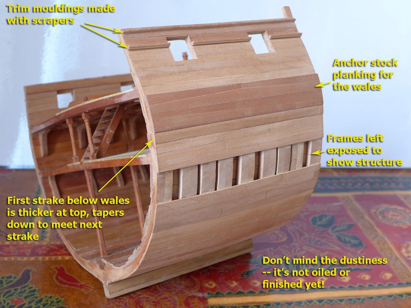
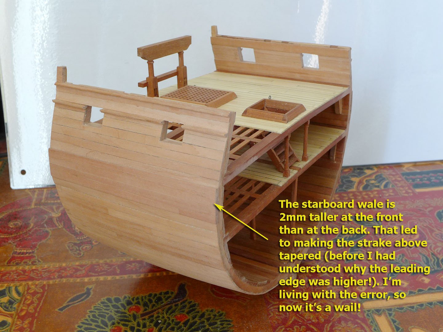
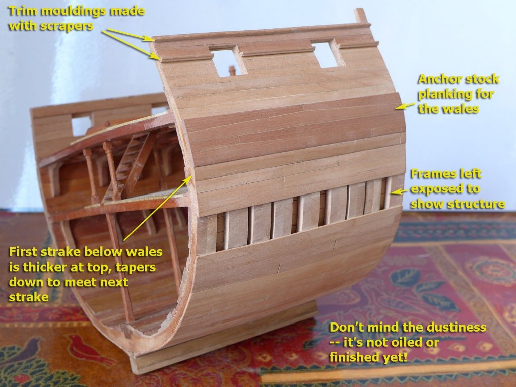
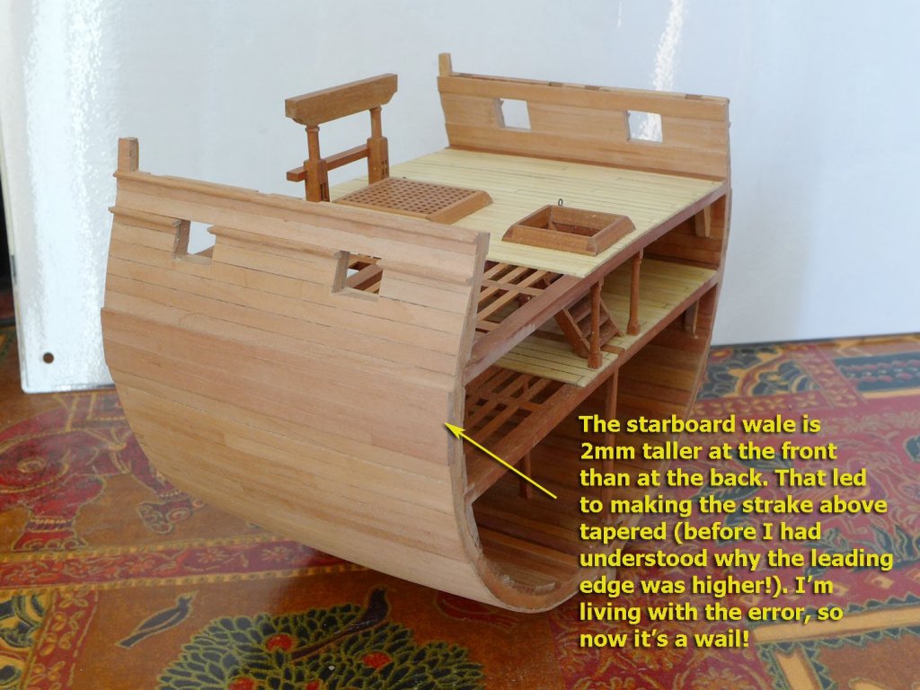
 PLANKING THE OUTER HULL I thought I’d have a bash at anchor stock planking for the wales. This proved to be a bit tricky without making a special jig from metal. I did try using a sander, but in the end the method I used was to paste a template on to wood and sand that down using a sanding stick. It would be far better with a jig, of course. Perhaps next time! Having prepared the planks, an important question was how to place them so that the butt ends would lie over frames. So I used TurboCAD to superimpose the planking outlines layer on the frames layer and move it until the ends covered the frames. This worked fine for the port wales. And on the port side the planking went easily enough. I decided to leave a section unplanked just to show how the hull was structured. It also was fairly straightforward to make the trim mouldings using an old hacksaw blade tempered over the gas hob to red heat and cooled slowly before cutting with a grinding wheel and filing. Unfortunately when it came to planking the starboard side, I found that the forward end of the wale was about 1.5mm higher than the aft end. At first I thought it was to do with the curvature of the hull as I thought I had measured the position for the wale fairly carefully. In this blissful ignorance I started the planking above the wale by trimming the immediately next plank to suit. It was only a little while later that I realised that I had not cut the top strake of the wale correctly, and it was in fact at an angle. Rather than unglue everything (I’m getting really short of wood) I decided I’d live with the mistake. After all, I reasoned, I’m not going to be showing this model to anyone, and I’m only using the exercise to learn. Seeing as I’d learnt from the port side, I reckoned I’d be all right for any future builds. Lessons learned! I followed David Antscherl’s book on the Fully Framed Model by making the plank underneath the wale to be 4” tapering down to the 3” of the planks beneath. So I’ll now be continuing with the gangway knees and placing the guns. Tony
- 132 replies
-
- 15
-

-
- triton cross-section
- cross-section
- (and 1 more)
-
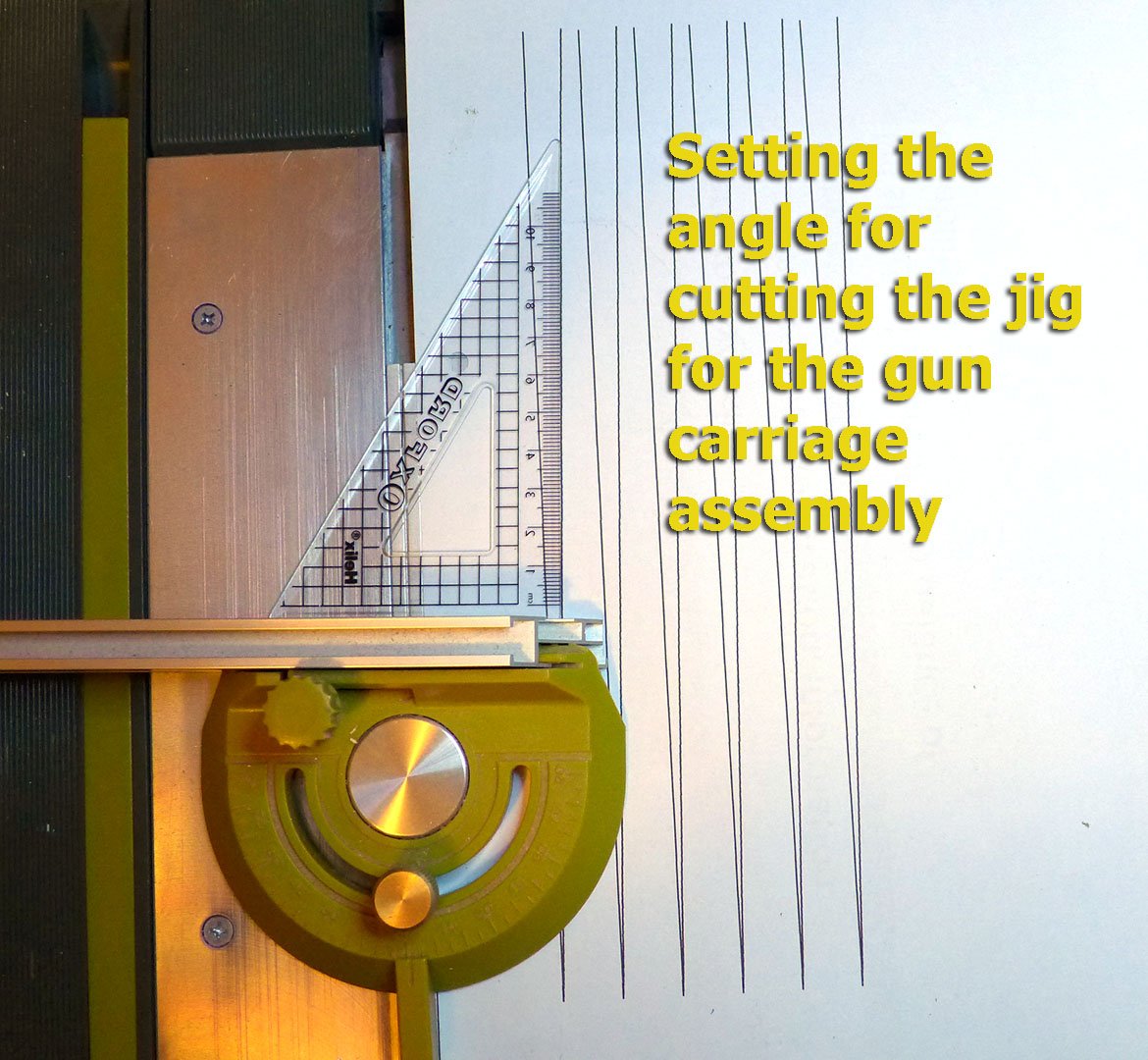
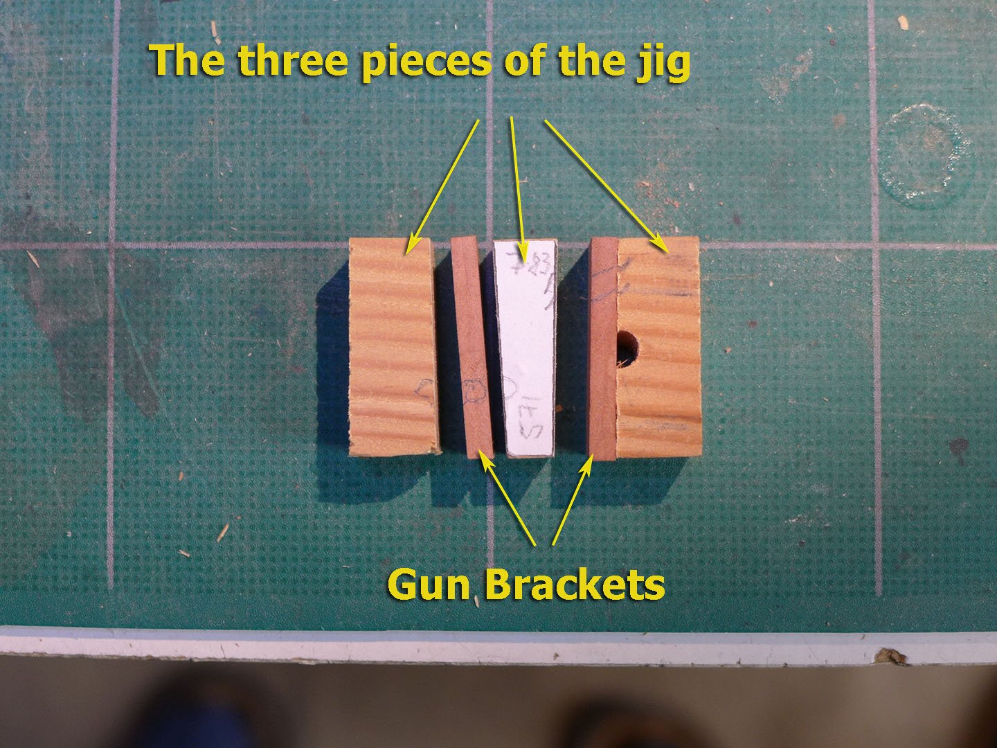
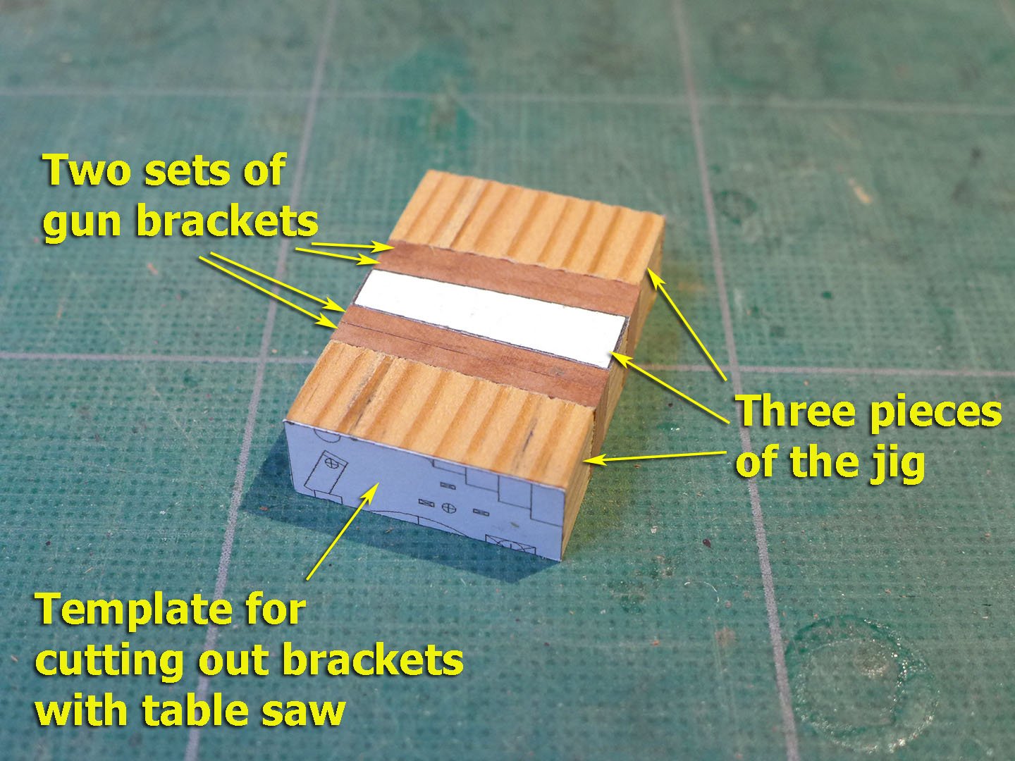
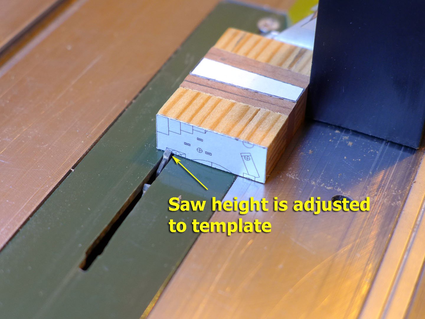
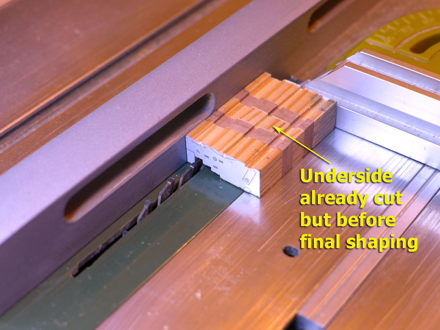
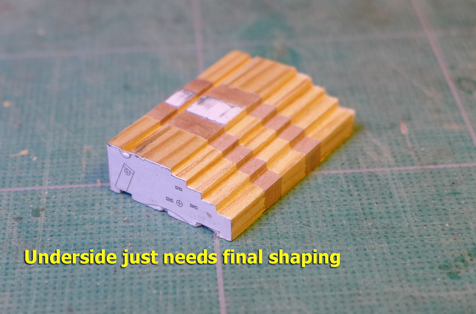
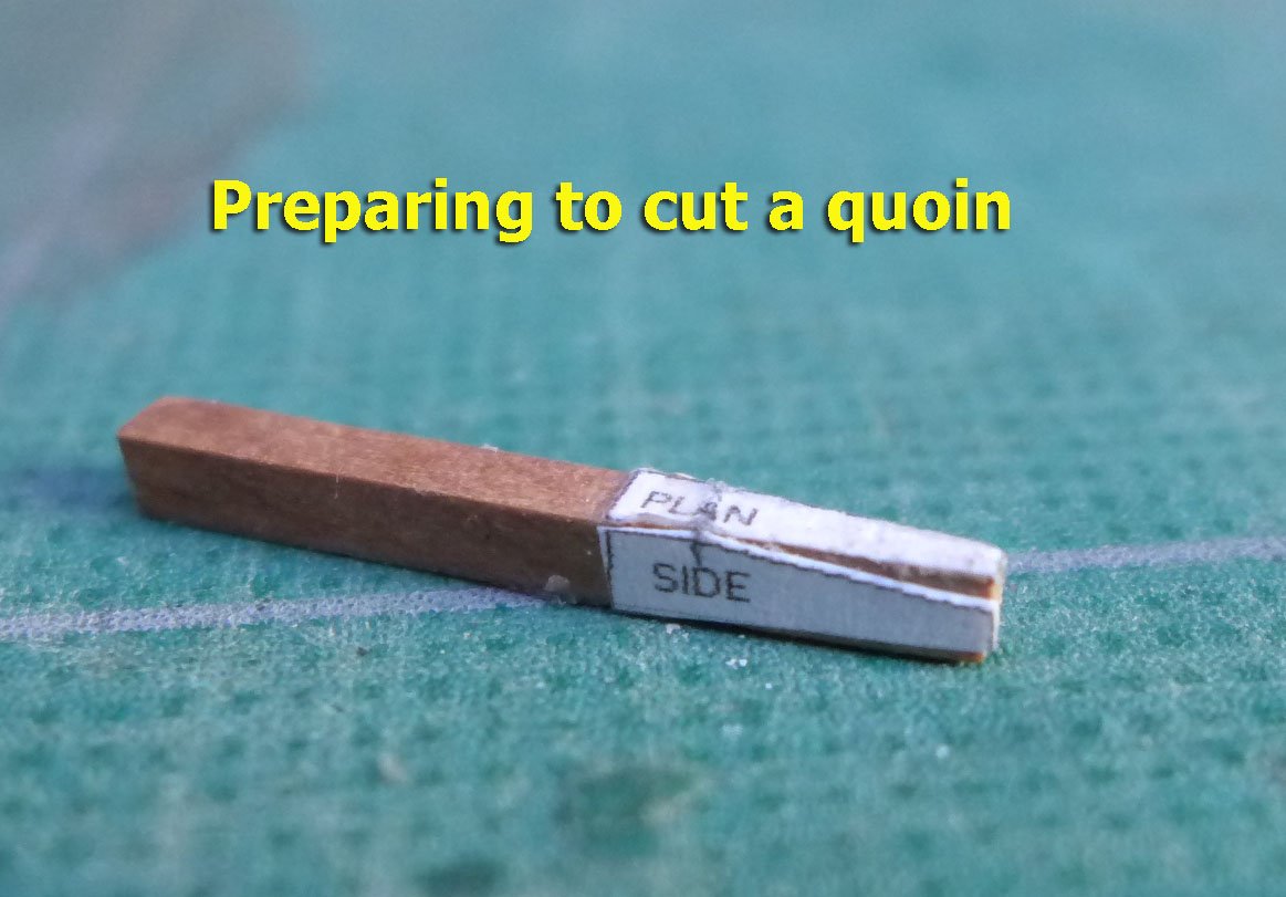
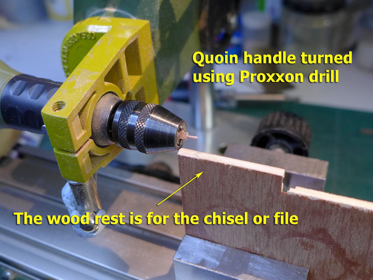
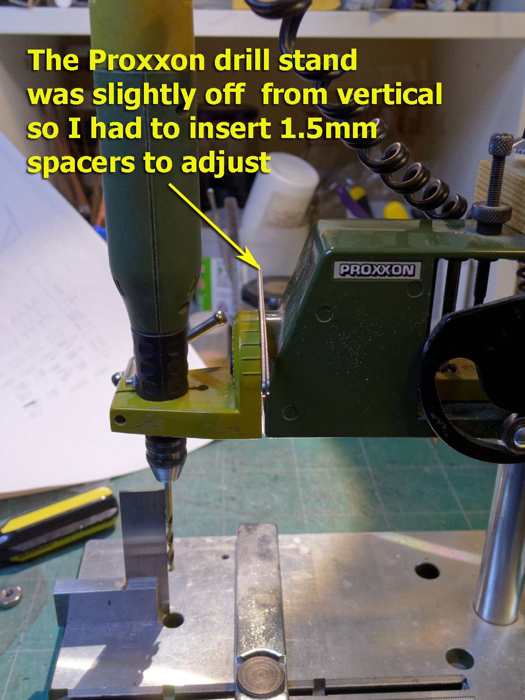
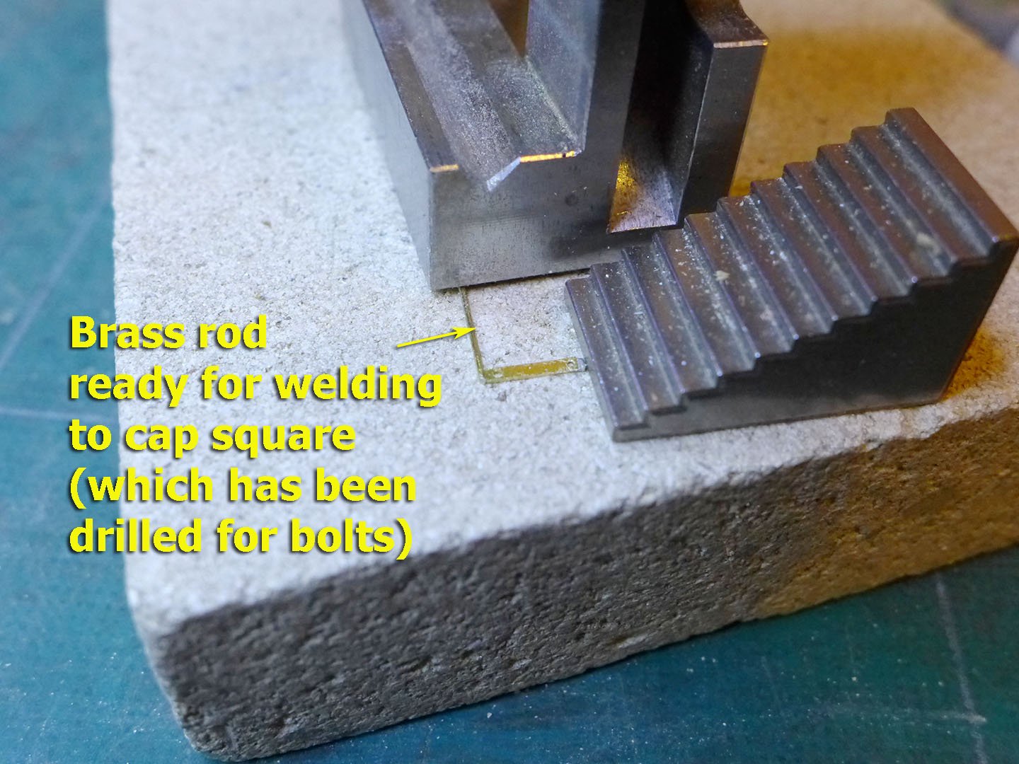
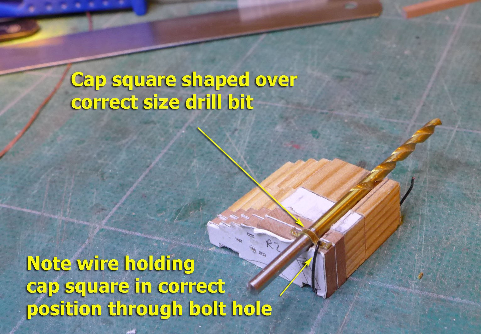
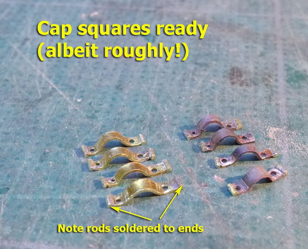
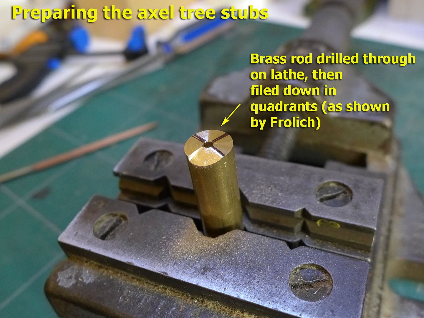
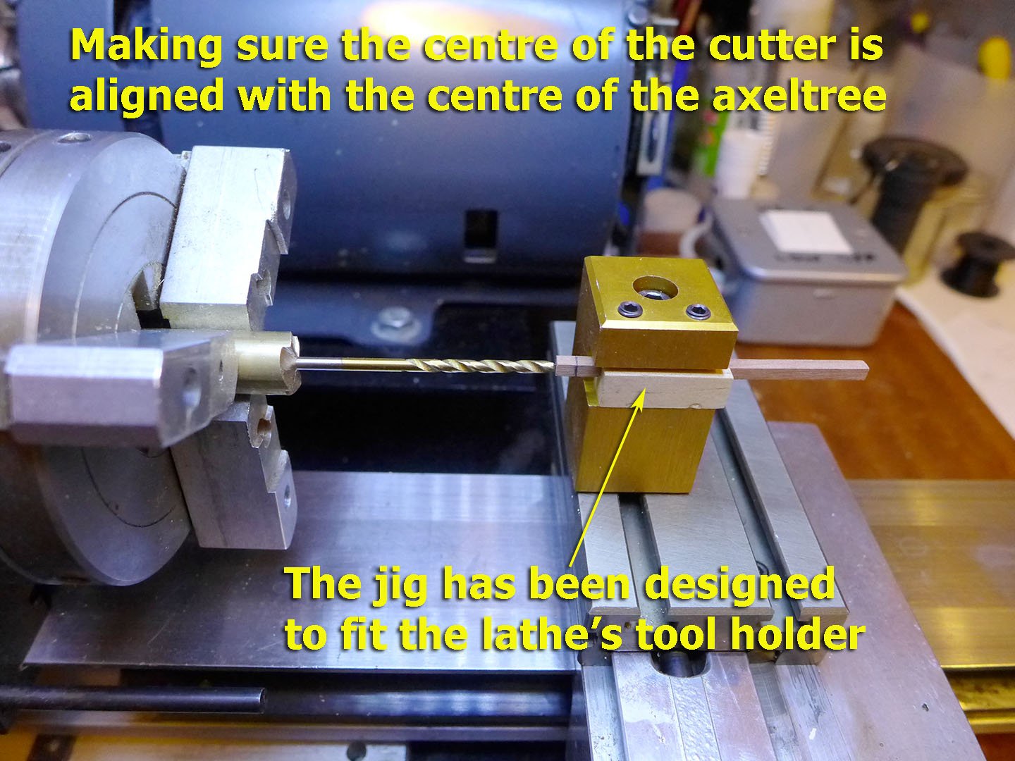
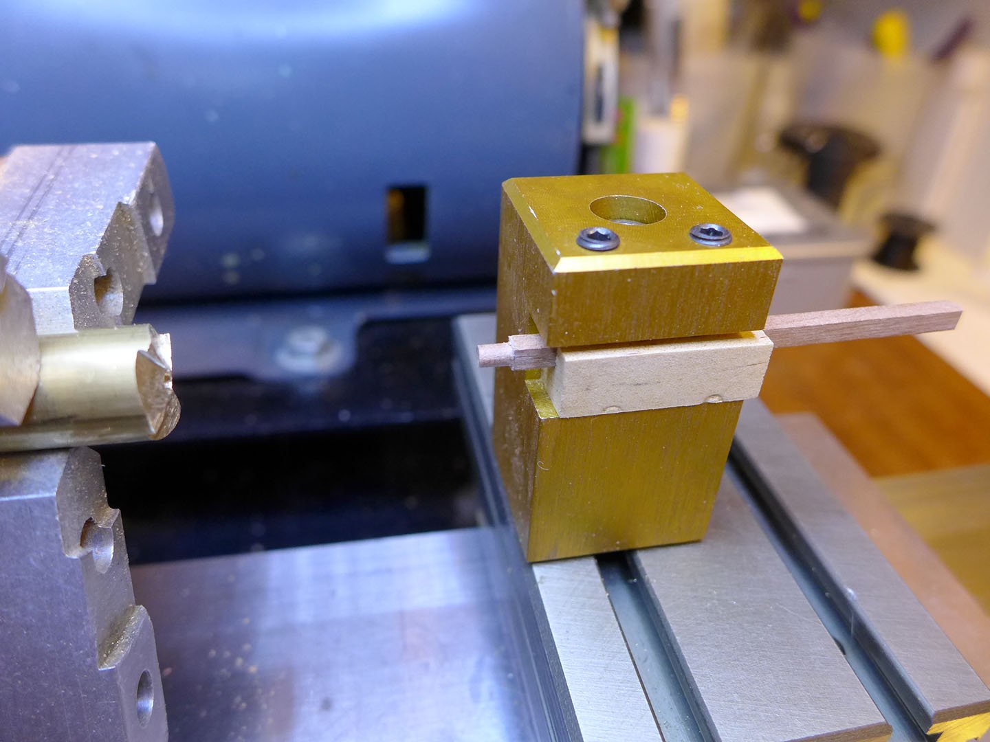
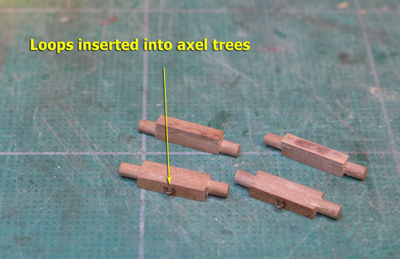
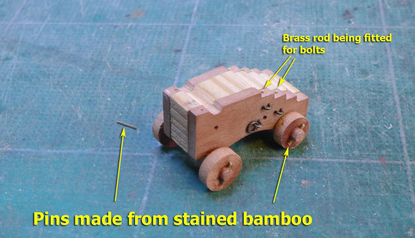
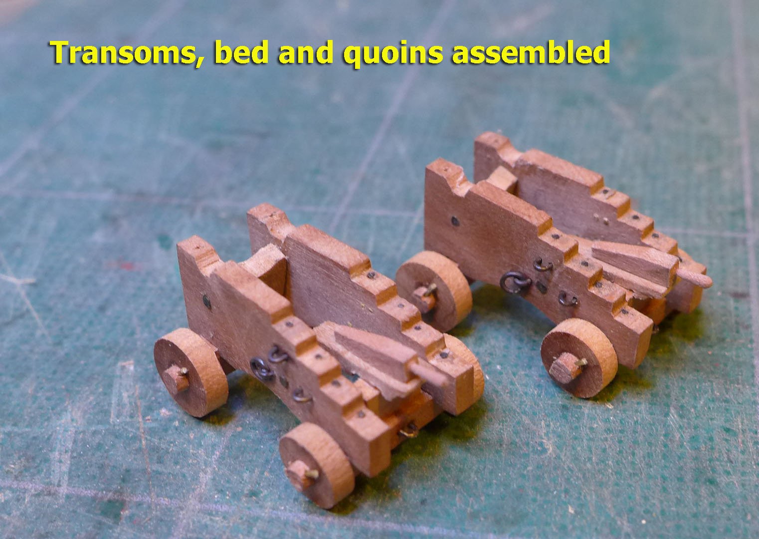
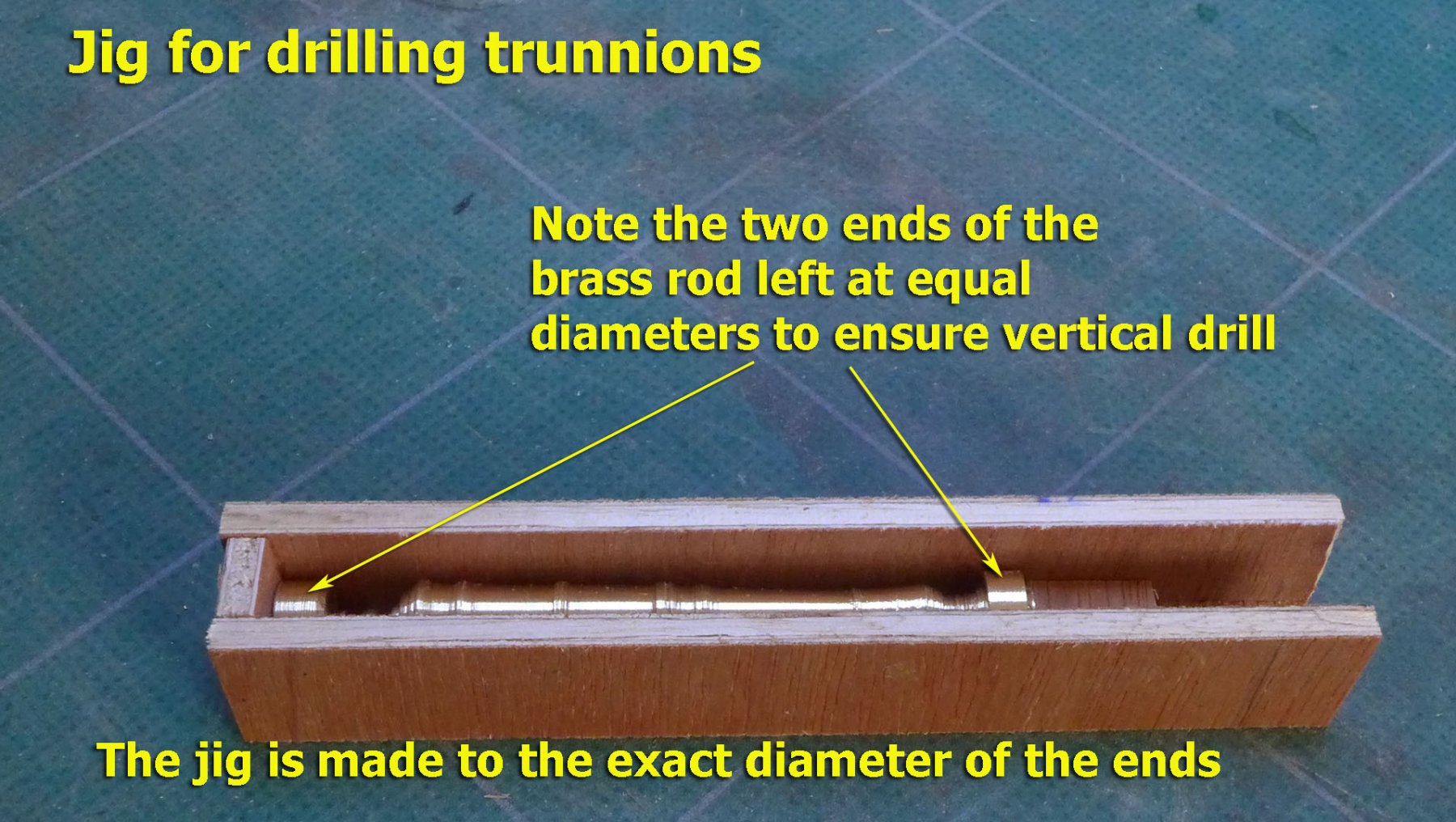
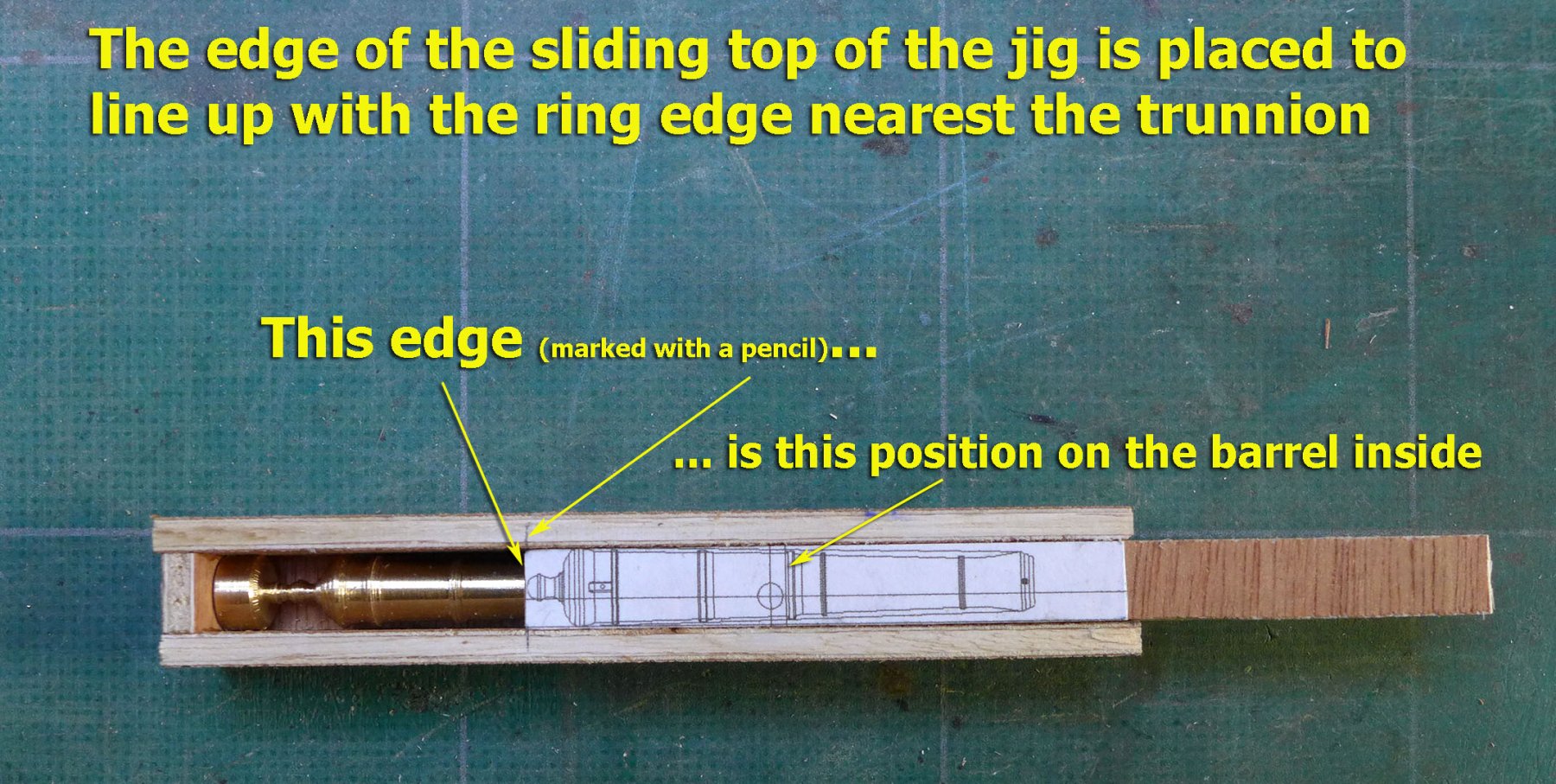
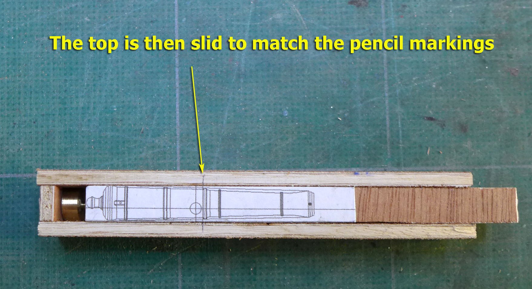
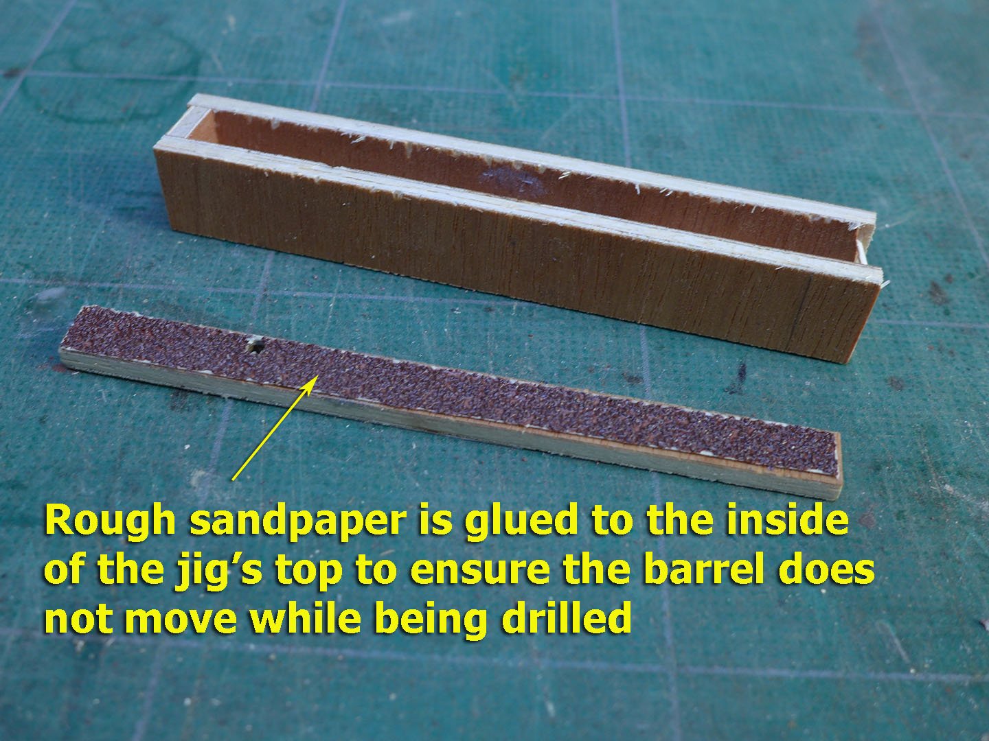
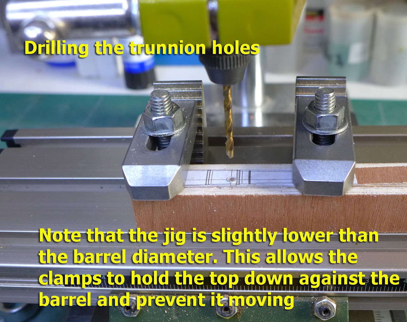
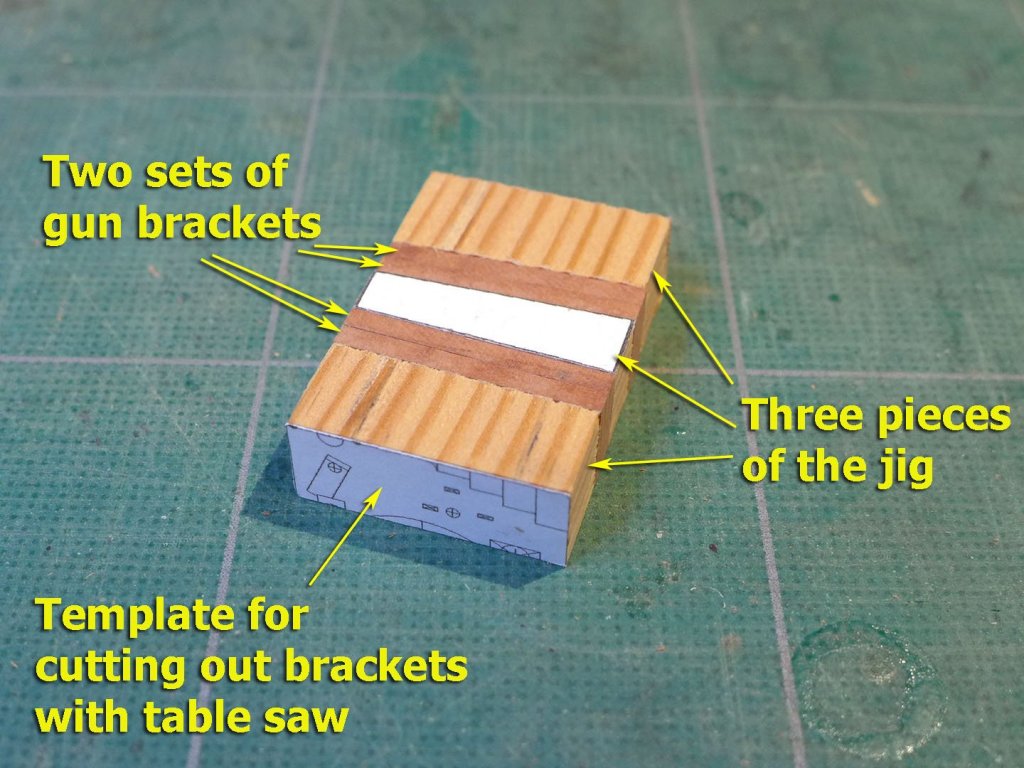
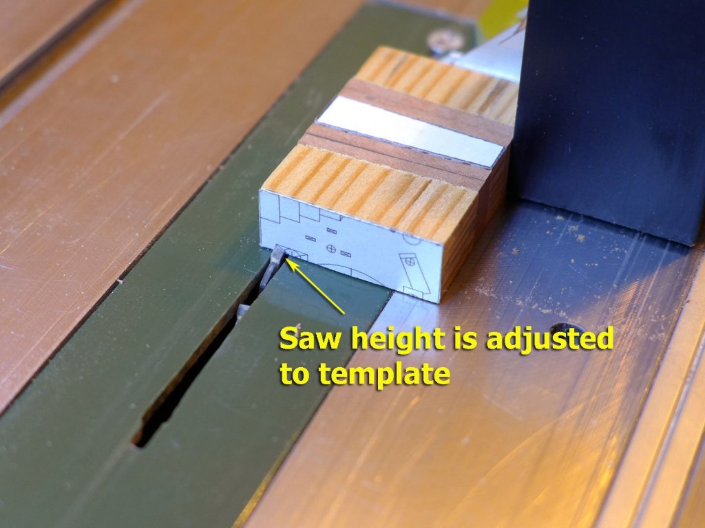
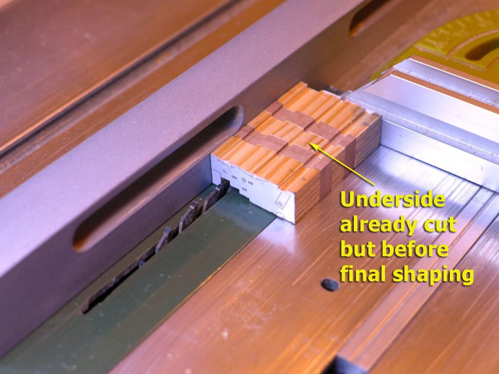
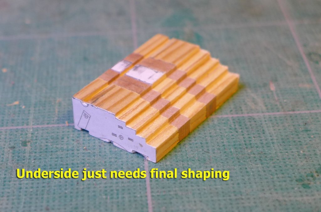
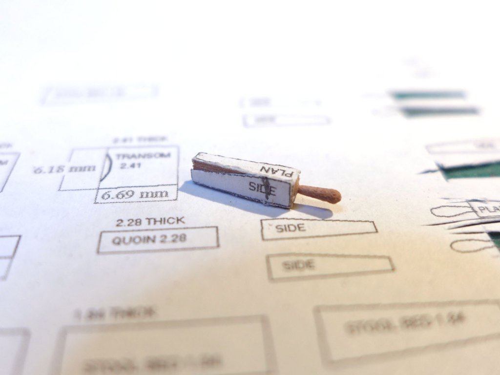
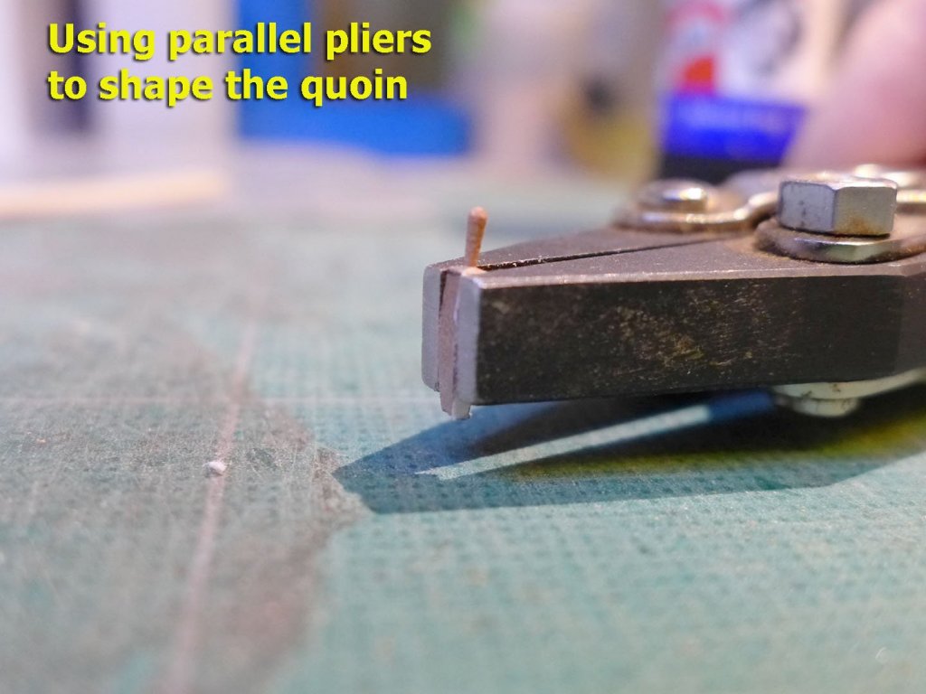
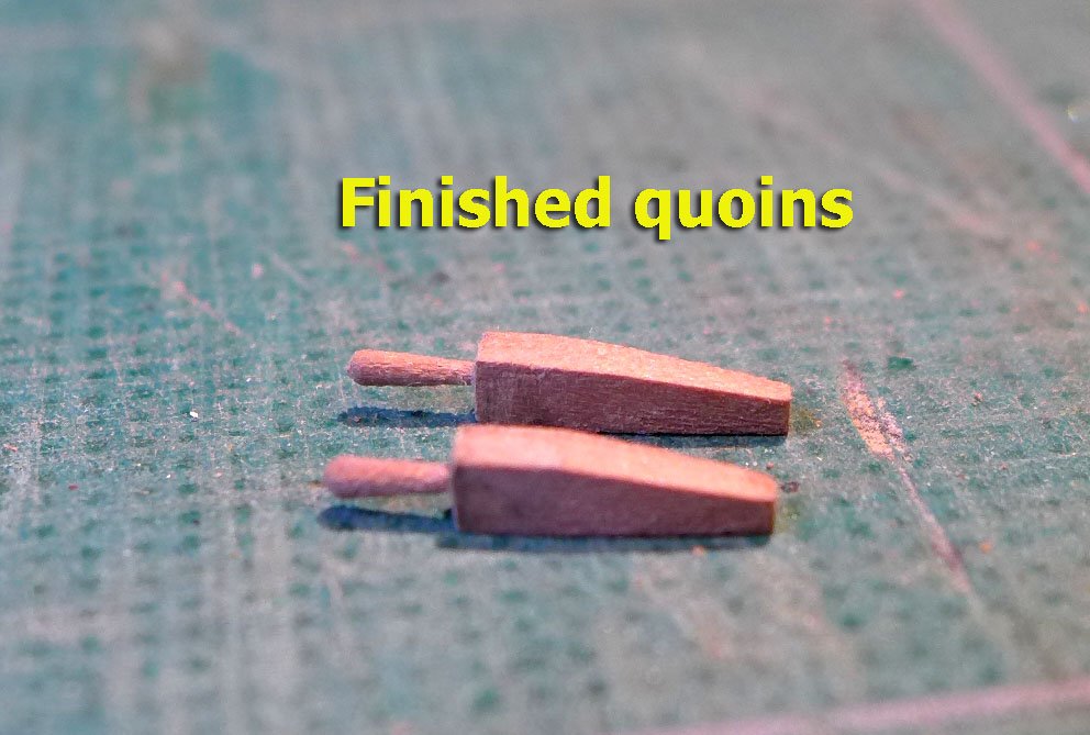
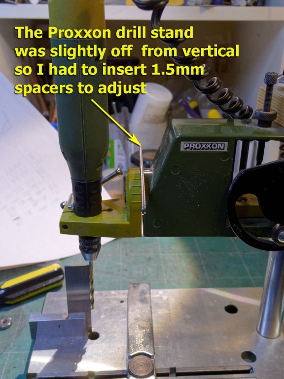
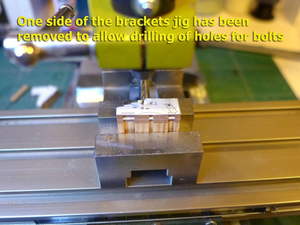
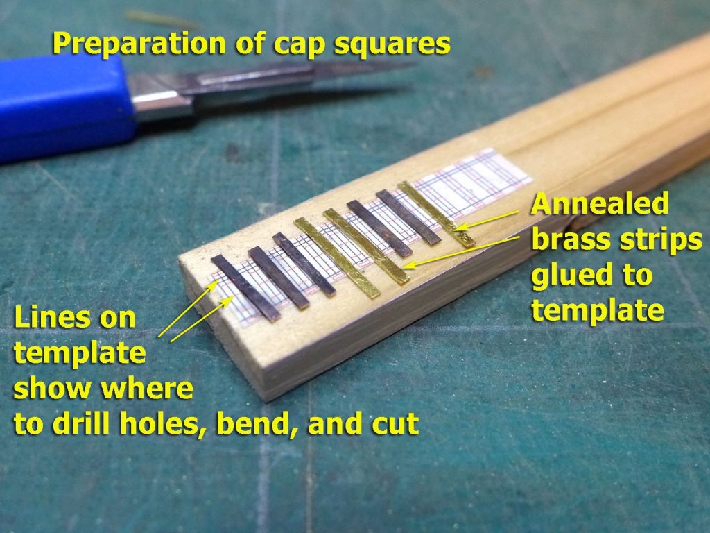
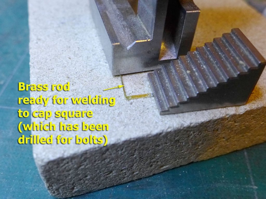
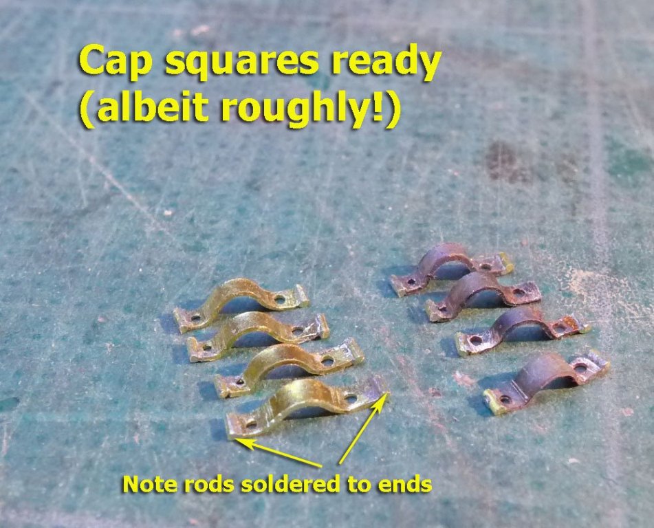
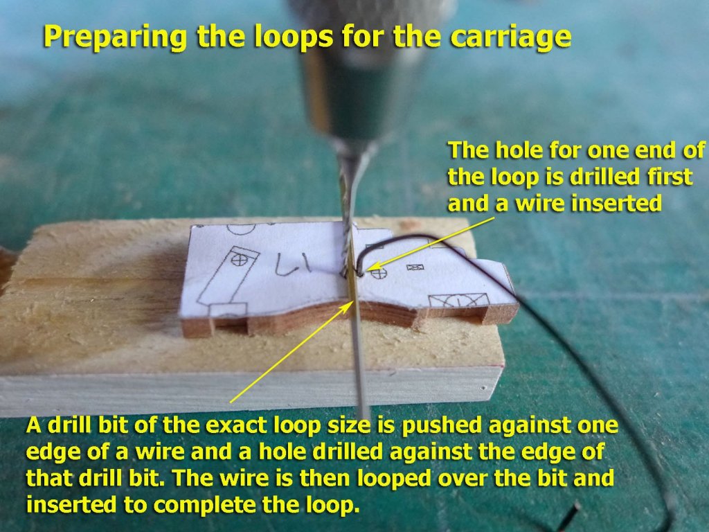
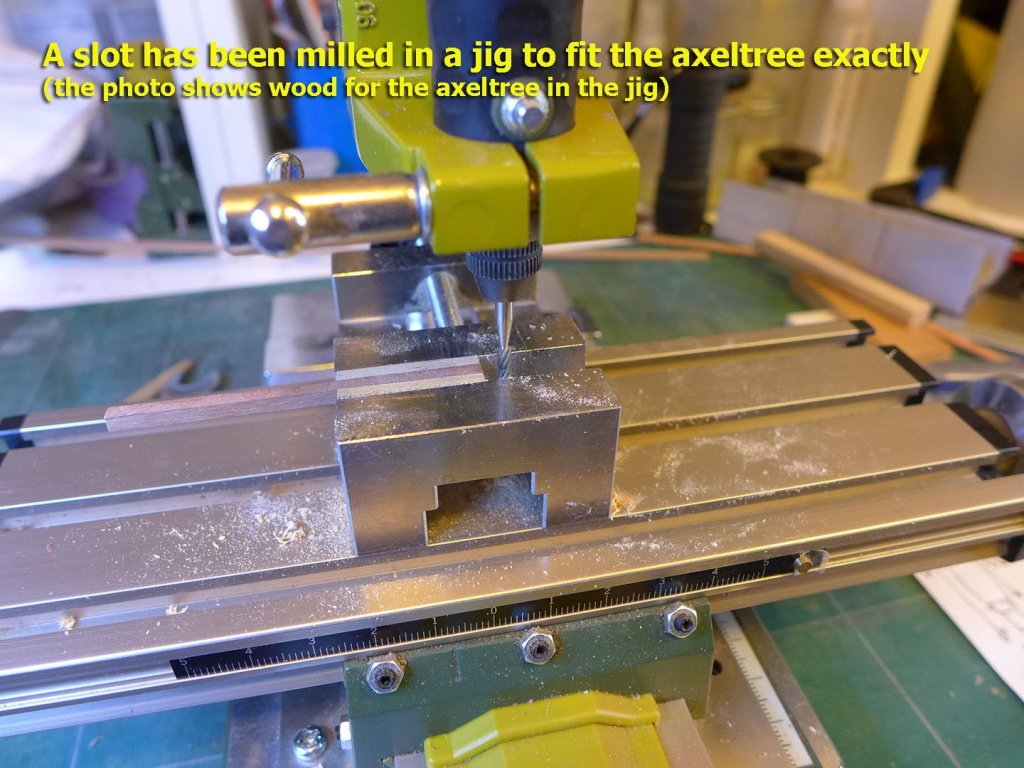
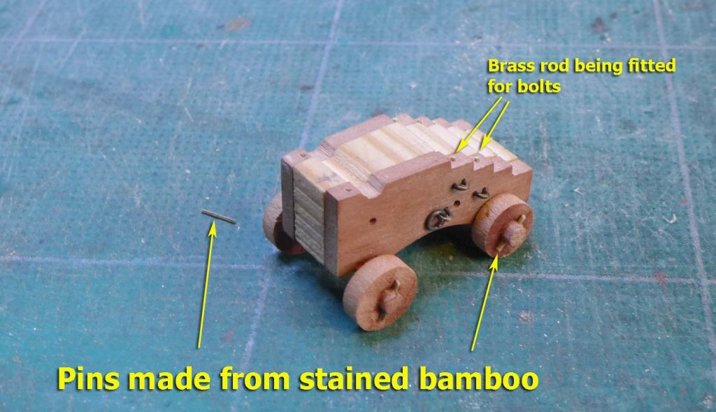
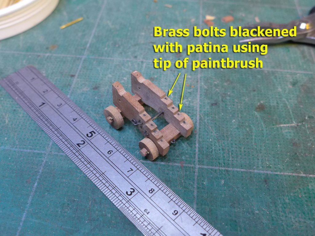
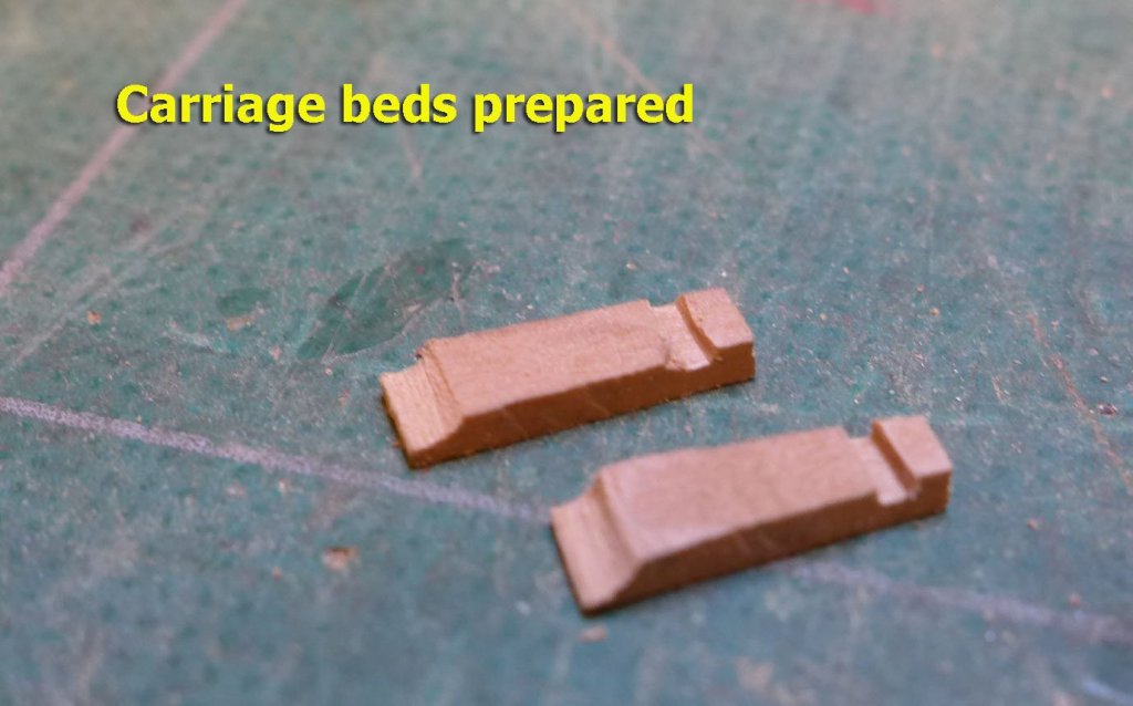
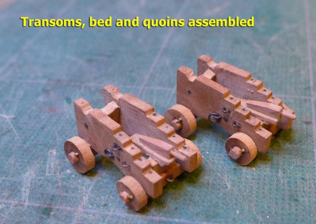
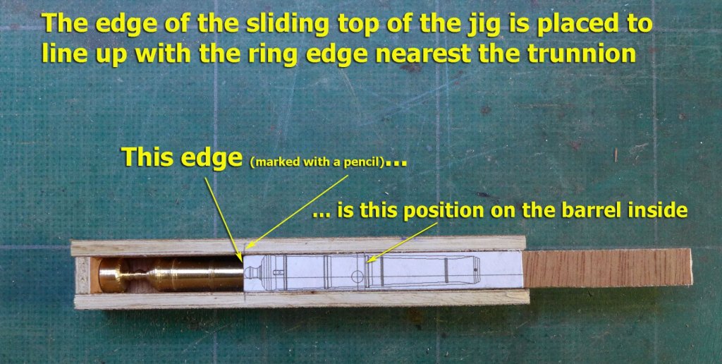
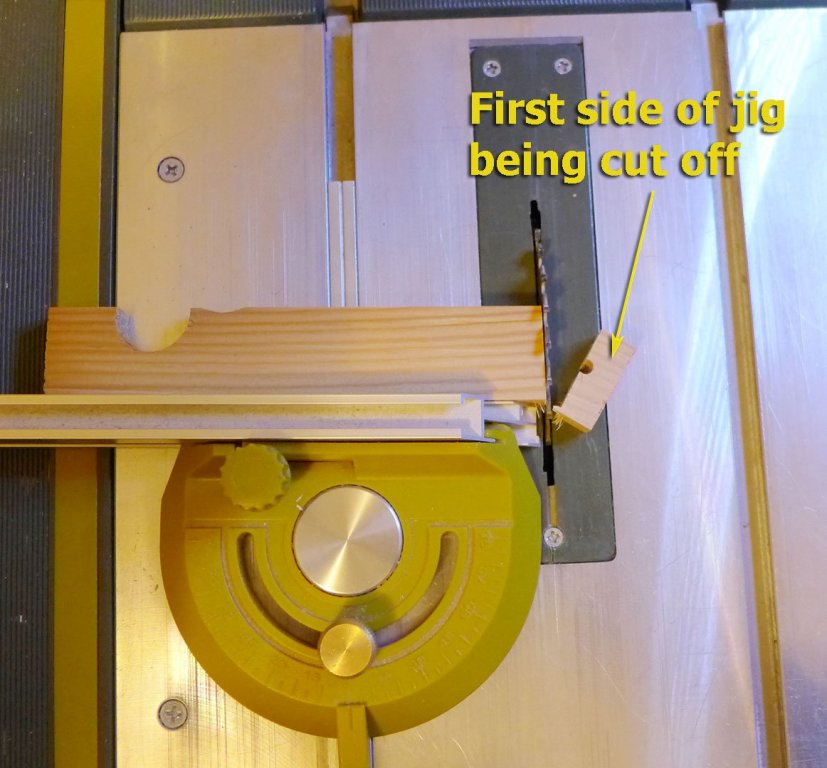
A ROUNDABOUT WAY OF DOING THINGS I ended the last part of my log with the statement “I need to finish the planking of the gun deck walls, sand down the fore and aft section faces, and then I’ll be working on installing the eyebolts for the cannon and making up the gangway brackets”. Well, it became a bit more complicated than that. I did start by planking the gun deck walls, but then worked on the gun carriages in the thinking that it would make more sense to fit the bolts once the guns were done. Then, once the carriages were done, I reckoned I’d need to place the gangway knees so that I’d be clear about the placement of the bolts. That drew me into a discussion about where the aft guns would be rigged to since the gangway knees cover exactly the correct position (according to the plans) for the bolts for the gun rigging. So I made the knees following Grant’s Triton build, but then reckoned that it might be better to complete the outer hull planking before working on the inside – in the belief that with all the handling of the outer hull any more done on the gun deck and gangway might well suffer. So I did the planking. And then I realised that unless I documented progress in my log, the task of writing it would become too big and bothersome. So although I’ve completed the gangway knees, I’ll just concentrate in this section of the log on the guns and the hull planking. THE GUN CARRIAGE BRACKETS Having had experience with the small cannon in the Sherbourne, I wanted to avoid the problem of drilling holes through the brackets when they are not parallel to one another. So I made a jig, as documented in the following photos. First was getting the angles right for the jig. To save time, the jig allows for several pairs of brackets to be cut at once. I’m only making two guns, so there’s more than enough room for the jig. Setting the height for the table saw was simple using the template I’d made with TurboCAD. QUOINS Using a simple template and making the handles with the Proxxon drill being used as a lathe was quite simple: DRILLING THE BRACKETS FOR THE BOLTS When it came to drilling the brackets, I decided to double check the verticality of my drill stand, as I’d noticed that when making blocks there seemed to be a very slight deviation. There was. It was small, but enough to be a problem. Luckily, the solution was the simple addition of a 1.5mm wedge into the stand as shown in the following picture: And with that corrected, I then unglued the outer part of the brackets jig, placed another template on the side, and drilled away. CAP SQUARES I fiddled around a bit with black paper to make the cap squares, but finally thought it would be better if I could make them from brass. My efforts didn’t turn out nearly as well as those of the experts around here, but I still enjoyed the process of learning. LOOPS FOR THE CARRIAGE RIGGING Instead of using simple bolts for the loops, I decided to use David Antscherl’s measurements for the loops and make some loops of my own. This was far simpler than I expected, using 0.5mm black-coated copper wire as follows. TRUCK STUBS I decided I’d try out Frolich’s method of making the truck stubs. This involves making a cutter from brass rod, and cutting in a lathe. TRUCKS It was easy to turn the trucks on a lathe and then cut them off with the table saw. The pins for the trucks were made from bamboo strips passed through a drawplate and then stained. The vertical bolts were then added as brass rod and then blackened with lead patina using the tip of a paintbrush. CARRIAGE BEDS AND TRANSOMS The beds and transoms made and fitted. DRILLING THE TRUNNIONS IN THE CANNON I thought I’d try a more accurate method of drilling the trunnions than the one I used for the Sherbourne. First off was to cut the cannon whilst leaving both ends of the brass rod at the same diameter. This would mean any vertical drilling would be easy. So after turning the brass cannon on a lathe, I made a box to the exact diameter of the outer stubs. I then made a cover with a template of the cannon that would fit just inside the top of the box. The height of the box was made a little smaller than the diameter of the cannon stubs, and a piece of sandpaper fitted to the inside of the lid: that would ensure that when clamping the jig the cannon would not roll round whilst drilling. I used as a marker the edge of the reinforce ring nearest the trunnion. I’ll show the assembled guns in a future post, but my next section will deal with the planking of the hull. Tony


- 132 replies
-
- 14
-
-
- triton cross-section
- cross-section
- (and 1 more)
-
Sorry, Grant, but I've only just caught up with your log and seen the issues you raised in post #169, viz: "The things I need to think about that I came away with were: Deck furniture issues with the boom pin rail and windlass and position of pretty much everything, the first model showing the companionway forward under the boom and facing aft with different grate/light positions. One question here is the second model showed 3 additional hand-cranked small windlasses, what are those and were they common? Topmast forward of the mainmast. Two sets of braces for main and top square sails. Only I don't understand why there are two sets, why not just run them forward to keep them clear of the spanker boom? Seems overly complicated to run them to two places." The first issue has been answered as the Trial shown in the picture had an experimental drop keel. In relation to the topmast, there was some discussion of it in the Sherbourne build logs by myself, Dirk (Dubz), Kester (Stockholm Tar) and Gregor -- as there was over a lot of other historical details to do with cutters. I made my own choice of putting it fore of the main mast not only because it was placed that way in a number of contemporary models and paintings, but also because it makes a lot of mechanical sense -- seeing that the mainsail rigging and all that weight now comes off the lower and larger mast. It might well be worth going through the logs I have mentioned above because the discussions also cover many of the points of interest you are likely to come across in the Lady Nelson. However often the decisions are personal, as the original NMM plans were either inadequate (e.g. gunport hatches, rigging) or hard to distinguish. In any event those NMM plans did at least point to a number of inaccuracies of the kit (companionway, windlass). And the kit pieces are often too gross for comfort (pumps, tiller, belaying pins, cannon). I'm only a novice (Sherbourne was my first build, and I'm still working on my second) so I'm sure others with greater knowledge will provide better answers. For the rigging, I would strongly recommend Marquardt's Eighteenth Century Rigs and Rigging, which can be obtained quite cheaply. It is a very good companion to Petersson, which is excellent for clarity and general understanding, but has a few errors of its own. I see that, just as for the Sherbourne builders, you've had your share of woes with the gunports. Some people ignore the cutouts in the kit bulwarks and make their own with planking cutouts after first assaying positions and heights with card cutouts of guns on carriages. Tony
- 714 replies
-
- 4
-
-
- lady nelson
- victory models
- (and 1 more)
-
Nice to know of another OU person on the hobby. I look forward to your build log. Don't hold back on the questions as you come across difficulties -- there's no such thing as a stupid question on this forum and you'll receive lots of help. Tony
-
Thanks, Ed. The two volumes are already with me and I've been studying them. They're helpful not only for what I'm doing now, but will certainly be of use for my next model (probably Le Rochefort) and then, quite probably, the Naiad. Tony
-
Thanks, Anguirel and Druxey, for your thoughts. I was looking at the possibility of the knee itself. I can see from TFFM that before 1780 it was more common for the knees to be made of wood and the knees would take the bolts, but in these plans of the 1773 ship they're made of iron so I thought that it might be difficult to put the bolts through them. I don't think the stairs will get in the way if I put the bolts the other side of the bracket, but I can see it's a bit crowded. I'm just turning the cannon right now, so I'll have another look when the guns are assembled. I am concerned that if the bolts go wider at one side there might be some imbalance when the guns are fired -- though in this particular case these guns will never fire and the ship would have sunk well before that being without a stem, a stern and half its planking. Tony
-
And a very nice evening for me to watch the progress! Tony
-
Ancre publishes the rigging and sail plan for €18. It's written in French, but I don't think that's an issue with understanding the plans. You can find it at http://gerard.delacroix.pagesperso-orange.fr/Chaloupe_greement/plaquette.htm. The plans were being given away free with the Rochefort monograph for a while, but I think that has now stopped. Tony
-
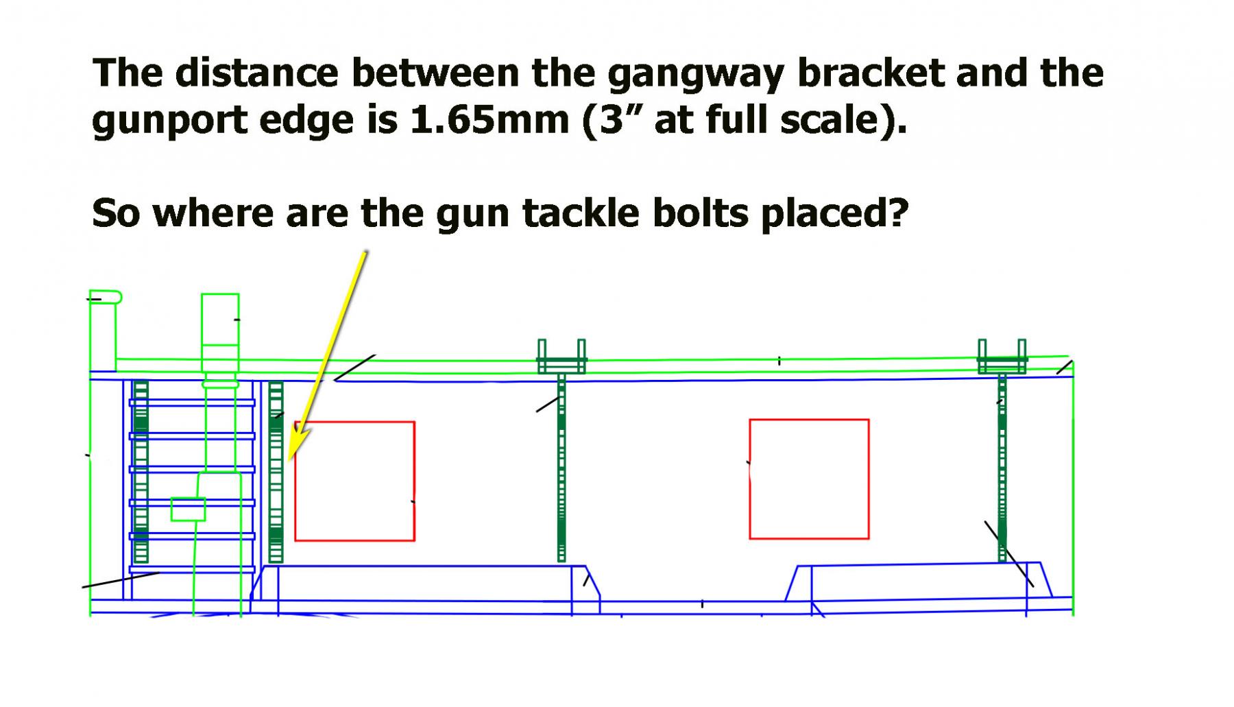
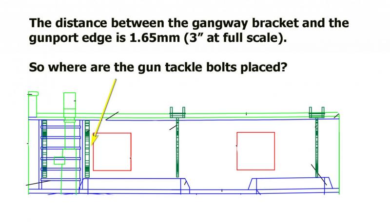
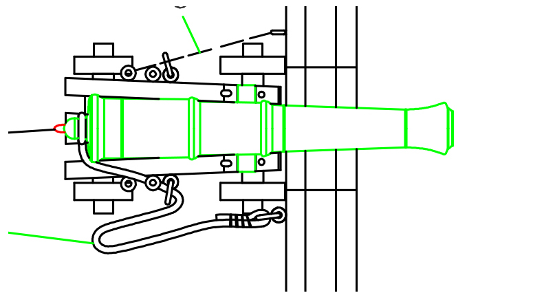
I've been puzzling where to place the two gun tackle bolts aft of the rearmost gun on the cross-section. The plans for the gun tackles clearly show that the bolts be placed at 3.17mm and 4.35mm respectively (at 1:48) from the edge of the gunport, but the aftmost gun bracket placing means there's only a 1.65mm space between it and the gun port. The bracket itself is 2mm wide. I suspect that the bolts would therefore have to be placed on the other side of the bracket, a bit wider than indicated by the plans, but I thought I'd better check with the more knowledgeable here before drilling for either bracket or tackle bolts and rings. Thanks as usual for any help! Tony
-
Michael Mott Designed Third Hand
tkay11 replied to BANYAN's topic in Modeling tools and Workshop Equipment
OK. Just found the plans for the wood version as well as the other concept drawings. Thanks, Michael! Tony -
Michael Mott Designed Third Hand
tkay11 replied to BANYAN's topic in Modeling tools and Workshop Equipment
Are there plans available for Michael's tool? I do see how it could be done, but plans would be a great help! Or are they on another thread that I've forgotten? Tony -
There is no problem with seeing any of the models that were in the Science Museum. All you have to do is email them with a list of the models or model types that you would like to see and they will send a spreadsheet with the details of everything you asked for including the places where they are stored and their full provenance. You then send them an email specifying the places you'd like to visit and they will arrange an appointment for you to visit that place. I have now done that with their storage units in Blythe Road and at Chatham (as documented in several previous posts). What's more, when you're there, the curators will spend the entire time with you should you wish to discuss the models. In general they give a 2 hour time slot but you can request more. You are free to photograph as much as you like. The huge benefit of this is that you can be as close to the model as you wish although they don't really like you touching the models. So there's no glass screens through which you have to photograph. I find this an amazing service. What's more it's entirely free, and that includes free entry to Chatham should you find models stored there that you want to see. Tony
- 3,618 replies
-
- 10
-
-
- young america
- clipper
- (and 1 more)
-
I did use Hubert's idea a lot for my Sherbourne, but then I settled in the end for making the seizings by hand. I found the CA could sometimes crack in the middle of a seizing after a day or so as well as leaving a glossy or speckly appearance. I also found that making the seizings properly was in the end just as quick as using the CA method. That said, however, I did find that making very small thimbles of various sizes by wrapping thread round a drill bit and covering with CA was a very useful way of doing it and I'll probably continue to use the method for that purpose. You can see examples at http://modelshipworld.com/index.php/topic/335-hmc-sherbourne-1763-by-tkay11-finished-–-caldercraft-–-scale-164-a-novice’s-caldercraft-sherbourne/?p=420952 Tony
-
One thing you might consider for future builds is that quite a few don't put the stem, keel and sternpost on until the first (or even the second) planking is done (at least in this kind of double-planked kit). That way you avoid damaging those parts, the sanding of the bearding line is easier, and you can figure out the rabbet more easily. I too didn't learn that until after the fact! I don't know the extent to which the Lady Nelson builds are similar to the Sherbournes, but the approaches to the transom on the Sherbournes was very variable. I'm not sure that the curvature needs to be the same across the whole width, but which ever way you do it bevelling is going to be part of it. Tony
- 714 replies
-
- 3
-
-
- lady nelson
- victory models
- (and 1 more)
-
You're absolutely right. It's unavoidable -- even if you didn't post a log. But it's also highly enjoyable. One of the problems is that some decisions have to be made early on in the build as changes can't be made later. Belaying points, mainstay holes, windlass, pumps, gratings, cannon rigging, horses and transoms are among the many cases in point. The other thing is that not only are you learning from a set of plans, but you also raise questions in your log to which answers are supplied by others and which you will probably find hard to ignore. You have already been driven to having a peek at what some books (e.g. Petersson) may have to say about aspects which are left very unclear in the plans. Then you'll probably find yourself unsatisfied with the rough look of particular aspects of the kit (e.g. the cannon, the pumps, the tiller, the rudder, the transom) and find out how they may have looked in reality. All this information still allows you to do it 'your way' in terms of the decisions you make about which way you want to go given your skills, tools, and level of accuracy you wish to maintain, as well as which of the original varieties of cutter mods you wish to make. You're finding out exactly what so many others have found (e.g. myself) when starting a kit -- notably that you don't want only to follow the kit instructions without further exploration and questioning. One reason why so many start a kit and then give up is that they don't think that questioning may help them through their build, and that is the beauty of this forum -- everybody wants to help each other, as well as to learn from each other. And this learning is part of the fun. Tony
- 714 replies
-
- 6
-
-
- lady nelson
- victory models
- (and 1 more)
-
I posted pictures of my visit to the NMM at Chatham to see particular models of cutters. You can see these at http://modelshipworld.com/index.php/topic/10370-18th-and-early-19th-century-cutter-models/?p=310186 It's worth going through the build logs of cutters on this site as most of them will provide interesting discussions on a variety of historical details of cutters, including the positioning of the companionway doors, bells, and so on. There are also others who have posted pictures of contemporary models in American museums. By the way, it's worth noting that even the books have mistakes -- Petersson, for example, has a couple that were discussed, so the discussions really are useful. It allows you to make your own informed decisions, since quite often there are multiple answers for the multiple configurations. Tony
- 714 replies
-
- 4
-
-
- lady nelson
- victory models
- (and 1 more)
-
I don't know the Lady Nelson model and I haven't looked in detail at any of the other build logs for the Lady Nelson, but looking at the pictures it looks like the companionway is the aft-most structure on the deck. Tony
- 714 replies
-
- 3
-
-
- lady nelson
- victory models
- (and 1 more)
-
Very nice progress. I don't really think the over-engineering is the issue since the filler blocks play a useful function if you want to mimic the planking that would have been laid on frames. The bulkheads don't represent the frames, so what some people do is to fill the spaces and then draw lines where the frames would have lain so that the planking can be laid according to the frame positions. That may be overkill rather than the over-engineering that might be seen from a structural perspective. In relation to gouging out the deck below the hatches, I found that matt black paint couldn't be distinguished from matt black space with the hatches in place. Tony
- 714 replies
-
- 3
-
-
- lady nelson
- victory models
- (and 1 more)
-
Gregor did a nice re-make of the stem to drill the extra holes. I never bothered as it was beyond my skill level at the time. As for thimbles, you can make them in a number of ways. A lot of people just use micro brass tubing. I made some of mine that way, and others from winding thread around a rod and then fixing it with CA. But then I didn't bother to shape them exactly as the originals. Tony
- 714 replies
-
- 4
-
-
- lady nelson
- victory models
- (and 1 more)
-
Really nice explanations of your process and build. Are you going to stick to the three holes at the top of the stem for the forestay as per the kit advice, or put in 5 as it would have been? If you have Petersson already, you'll have seen this, but I'm raising it now as it's the perfect time to drill those two extra holes. Tony

- 714 replies
-
- 8
-
-
- lady nelson
- victory models
- (and 1 more)
-
Very nice, Rob. I particularly like the colour scheme. Congratulations! I'm looking forward to the next build. Tony
- 25 replies
-
- 1
-
-
- finished
- sherbourne
- (and 1 more)
-
It's a nice ship to build, Jay, and you're off to a great start. If you haven't done so already, it's worthwhile to have a good look at the logs of the Lady Nelsons, Sherbournes, Cheerfuls and other cutters which are very similar and give lots of good suggestions for historical accuracy, rigging details or modifications you may want to make. I don't think it's a rite of passage to produce the build log. I think the idea is more to give people the opportunity to post their own progress and ideas -- firstly to help others who want to do the build, and secondly to discuss problems or questions they find as they arise during the build. The great usefulness of each log is that no two builds of the same ship are ever identical (just as no two ships of the same type were ever completely identical) and there is a huge variety of approaches to making the same pieces (even if you try to stick rigidly to the suggested approaches in the kit and use only their supplied pieces), so there's plenty of leeway to come up with your own way of doing things. Everyone also brings their own particular previous history, experience and tools to their builds. So each build is also unique in that additional way. There are approaches from almost every walk of life -- including carpenters, lawyers, engineers, dentists, doctors, archaeologists, anthropologists, readers of marine history, bus drivers, bankers, sailors, and 12 year old students. It's these aspects that can make build logs so interesting, especially when the builder gives great detail about their methods of construction and reasons for their choices. What is not so interesting is to see a build log just with pictures of final results, where the comments are just full of 'oohs' and 'aahs' and 'likes'. I look forward to seeing your own approach, expecially given your own skills and experience you bring to it. Tony
- 714 replies
-
- 12
-
-
- lady nelson
- victory models
- (and 1 more)
-
You have a great build going, so I wouldn't worry about being hesitant. I would imagine most people on the forum appreciate the detail of each step so they can see the techniques and tools used. This helps a great deal of us not only learn how to build, but also build up an armoury of ideas so we can tailor our own techniques to the resources, tools and time we have in our own models. Seeing the finished piece certainly allows 'oohs' and 'aahs' of praise, but you'll probably find greater comment and discussion if you don't worry about having it totally correct before posting. I've certainly learned a lot more as a result of being detailed in my logs about each step and each mistake. Tony