tkay11
-
Posts
1,824 -
Joined
-
Last visited
Content Type
Profiles
Forums
Gallery
Events
Everything posted by tkay11
-
 Thanks, Mike. I do them for other beginners like myself who are probably just as puzzled as I am at several stages of the build and who find pictures easier to think from than words (as I do). But I'd like to return the compliment as I very much appreciate the detail you put into your own logs. Tony
- 132 replies
-
- 4
-

-
- triton cross-section
- cross-section
- (and 1 more)
-
Yes, good idea Mike. Thanks for the tip. Interestingly I applied the same concept to a beam I cut 0.3mm too short. I glued on an old shaving and then sanded down gently for the correct fit. I'll be doing more of that in the future! On reflection I could have done that with the hanging knees, and I reckon I'll do that for the aftmost hanging knee adjoining the beam arm. And Brian: Thanks for the compliment! Tony
- 132 replies
-
- 2
-
-
- triton cross-section
- cross-section
- (and 1 more)
-
Thanks again, Carl and Dirk. As to the epoxy, Carl, it may be just my imagination, but I have the belief that it provides a stronger bond and I use it where I think there may be greater stresses than normal on a joint -- particularly when handling the whole model while sanding or whatever. I have found that while I concentrate on one particular action I quite often find I'm bending another piece out of its place, or, as I found with the frames, breaking them apart at the glue joins. I found that when I used epoxy those frame joints did not come apart again -- it was only those glued with PVA that did so. Of course I am quite ready to be corrected about the relative merits of PVA and epoxy so please do fire away! Tony
- 132 replies
-
- 3
-
-
- triton cross-section
- cross-section
- (and 1 more)
-
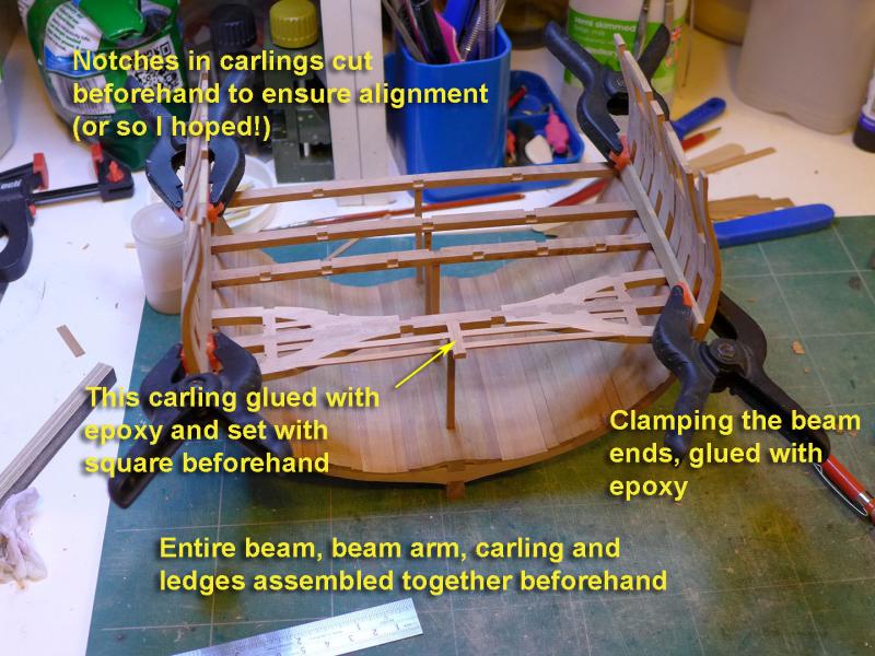
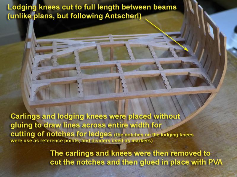
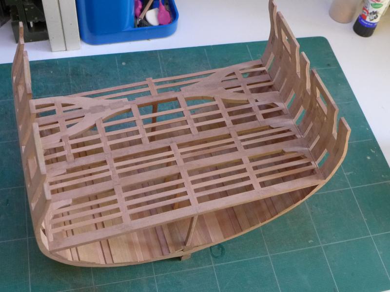
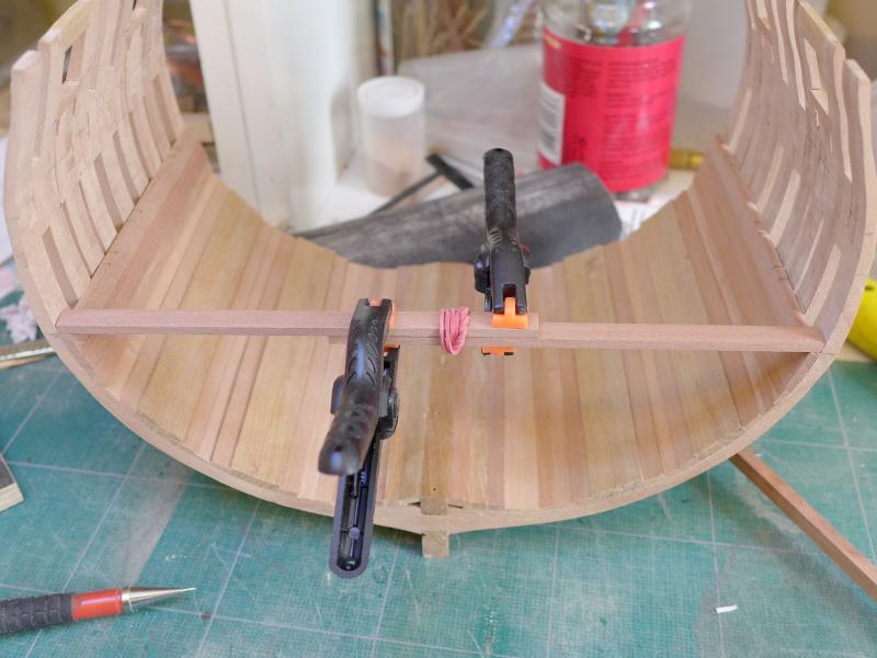
So practise I did, and I still have a way to go before the notches are perfect, but the nice thing is that the lower deck gives practice for the gun deck which will be more visible! Getting the beams on I thought it best to make the entire aft beam, beam arm, carling and ledge assembly before gluing the beams to the hull as I thought it would be too difficult to place the arms, carlings and ledges afterwards. That pesky little aft-most carling which will have no support at its aft end was epoxied in and trued up with a square beforehand as well. Once I had done that, I glued the beams to the hull with rapid-setting epoxy and held them down with the simple clamping arrangement shown in the photo. Lodging knees I then had a look at the lodging and hanging knees. It was immediately apparent that making the hanging knees fit perfectly was going to be a challenge well beyond my capability. So I had a read of Antscherl’s book on the Fully Framed Model, and he suggested that it was quite as likely for the lodging knees to cover the entire distance between the beams – unlike the current plans where the knees do not do so. If I were to make the lodging knees cover the full distance, this would make the construction of the hanging knees more easy as I’d only have to cut the pattern in relation to the planking below the beams. So that’s exactly what I did. Notch placement for the ledges In order to have the notches for the ledges between carlings line up across the width of the section, I placed the carlings in their notches and only then drew the lines across them from knee to knee using the position of the notches on the knees as reference points (and using a pair of dividers as markers). I then took down the carlings and cut the notches for the ledges before gluing them in place. After all this, placing the ledges was fairly straightforward. Of course there are lots of errors and slight misalignments, but as I said above, it makes for good practice for the gun deck. The next challenge, though, is to work out how to make and cut accurately the hanging knees for the lower deck. Onwards and upwards (to the gun deck eventually, that is)! Tony
- 132 replies
-
- 16
-
-
- triton cross-section
- cross-section
- (and 1 more)
-
Proxxon Micro Planer DH40 - owner feedback??
tkay11 replied to rtropp's topic in Modeling tools and Workshop Equipment
The best thing to do is to send an email to Proxxon. Whenever I have a question I write to Proxxon in Germany (in English). They always reply quickly and are very helpful. Tony -
I went with 8 3-pounders rather than 6, more to fill the ports! There was lots of discussion about this in MSW1.0. Lots of discussion too about whether to fit gunport lids. Some of those discussions are in a few of the existing logs. The kit barrels are too large for 3-pounders and the carriages not at all to scale or correct proportion, so if you're after a truer representation you have to make your own. There are plans in the resources section for an Armstrong 3-pounder. Tony
-
I forgot to add that you'll probably find that no two cutters are alike. They varied not only from decade to decade and type to type, but also from yard to yard and from owner to owner. Even more, you'll probably find that no two models or paintings of any cutter are exactly alike. It might be that if everyone stuck rigidly to the kit parts and the kit plans then you'd get some similarity, but even then you might find variations in sails, rigging etc. You'll note, for example, that the Trial was exactly that -- a trial ship (testing a lowering keel) built 27 years after the Sherbourne. So it had its own unique characteristics. This adds up to a general statement: you can choose what you want to do, at a level that's comfortable for you, with tools that you are comfortable with, with a level of detail that pleases you, and above all doing it in a way that keeps you happy while you accumulate skills and knowledge. Tony
- 69 replies
-
- 2
-
-
- lady nelson
- victory models
- (and 1 more)
-
I took a lot of pictures of cutter models when I visited the National Maritime Museum at Chatham. I had asked to see the ones in their collection and they brought the models out to show me in their warehouse. They moved the Trial to their collection there, and I included pictures of that as well. These pictures are far more detailed and close up than the ones you can see on the NMM website. You can see the pictures of the various models in my posting '18th and early 19th Century cutter models', and lots of discussion about the details in my build log of the Sherbourne. You'll also see lots of great discussion and in-depth analysis in other builds of the Sherbourne by Kester, Dirk and Gregor (each of whom did much better research and building than I was able to), as well as similar analysis in Chuck's build of the cutter Cheerful. If you search for 'cutter' in the forum discussions you'll find a wealth of knowledge and insight that will help you should you want to improve on the accuracy of the kit. Tony
- 69 replies
-
- 2
-
-
- lady nelson
- victory models
- (and 1 more)
-
ancre le rochefort by cabrapente
tkay11 replied to cabrapente's topic in - Build logs for subjects built 1751 - 1800
Wonderful work! Thanks so much for keeping up the detailed postings. They show what an interesting model this is. I have had the plans for a while now but am still learning my basic framing techniques before I start. So I hope that one day I'll be using your log to help me. Tony -
Thanks, Christian. Let's hope it continues to do so! I see lots of complexity and challenge ahead. Looking forward to it! Tony
- 132 replies
-
- 2
-
-
- triton cross-section
- cross-section
- (and 1 more)
-
Thanks for the likes, everyone! These, along with many, many cups of strong tea, will sustain me in my search for notch nirvana. It's possible several pages on the art of practice, failure and practice again will follow. I sure am glad I didn't start all over again as I can foresee that there will be several points along the way at which I will contemplate exactly the same. Tony
- 132 replies
-
- 3
-
-
- triton cross-section
- cross-section
- (and 1 more)
-
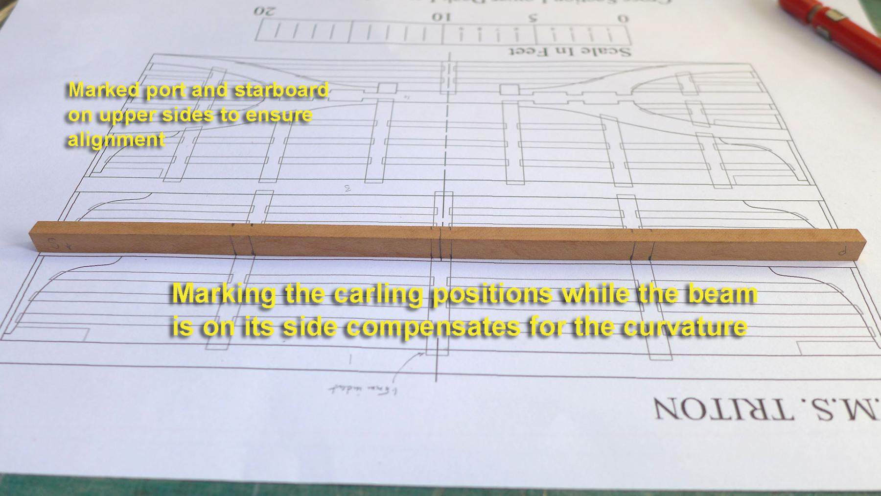
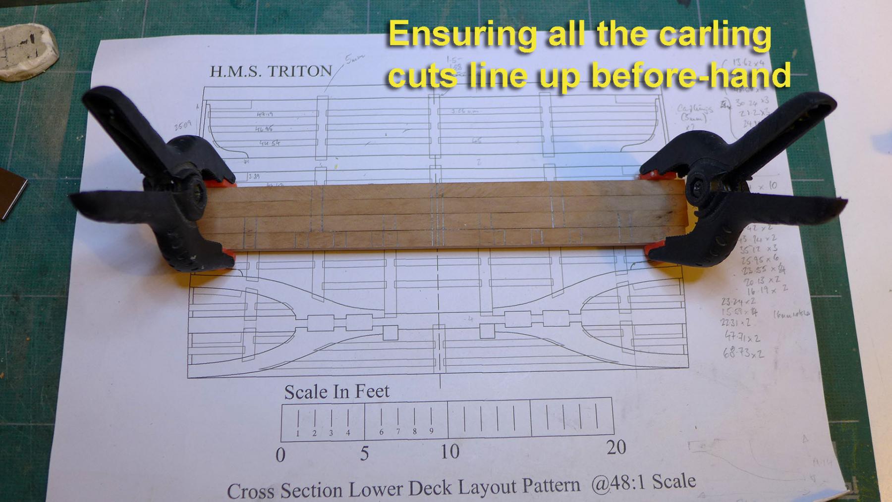
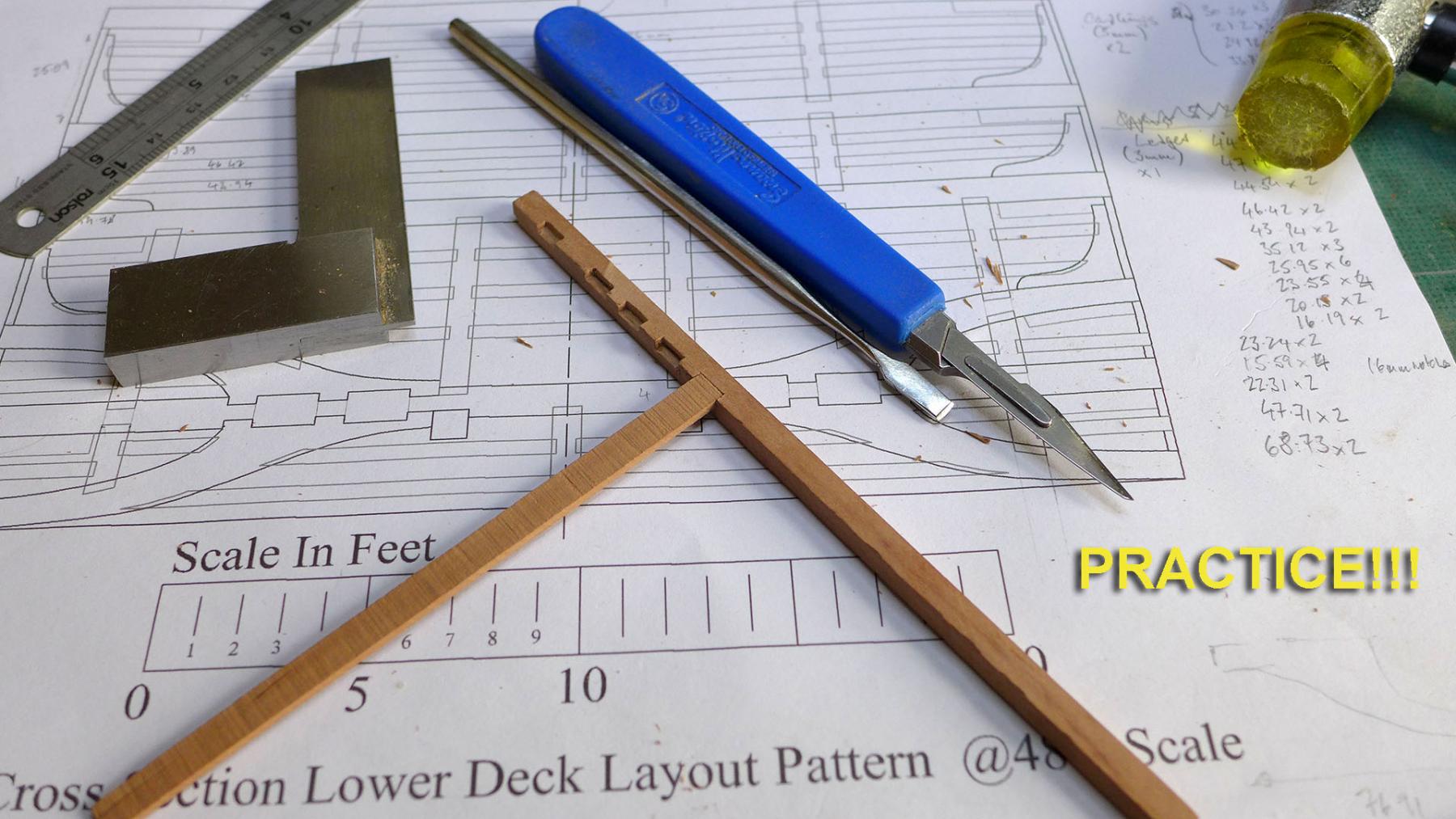
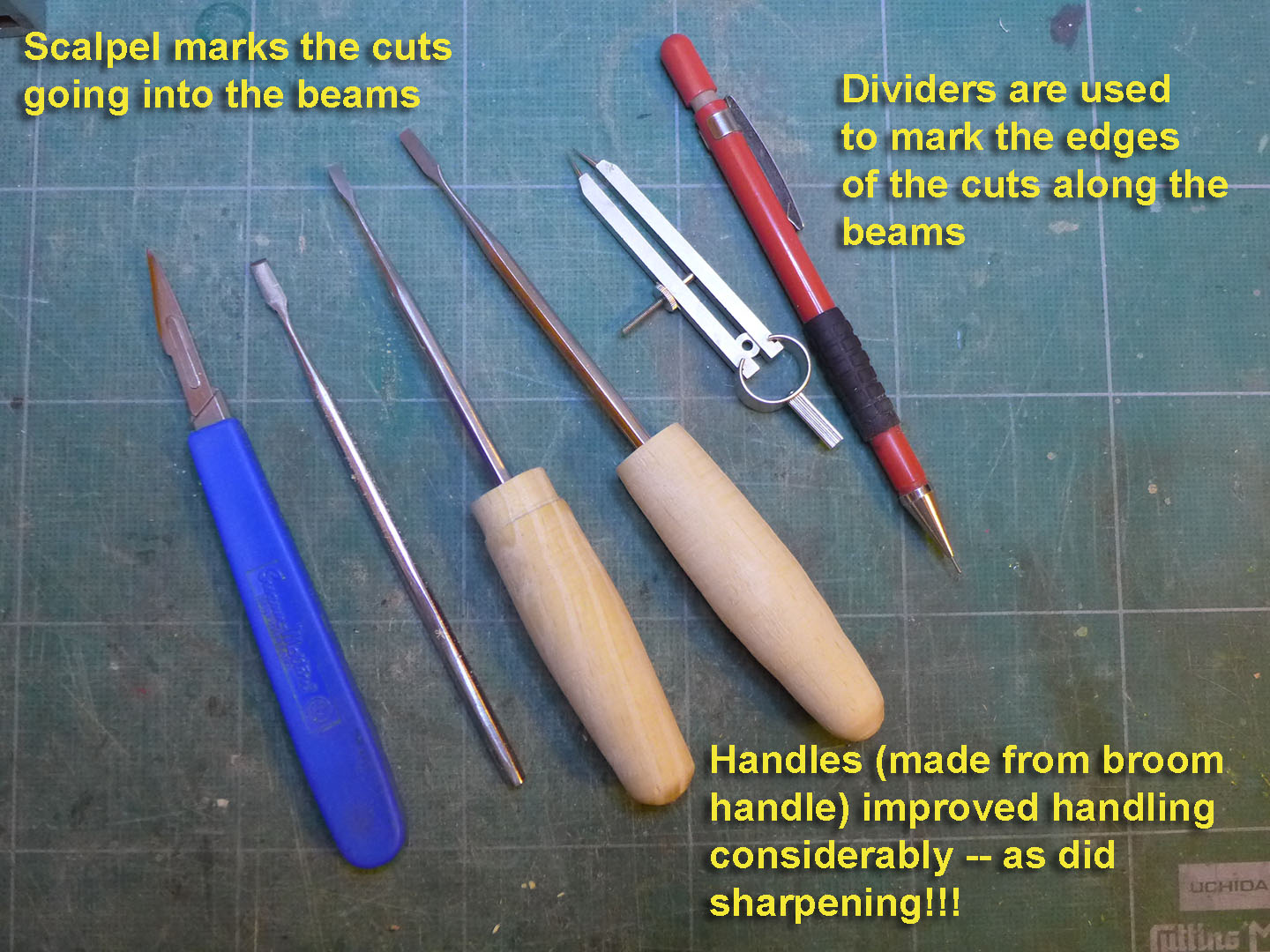
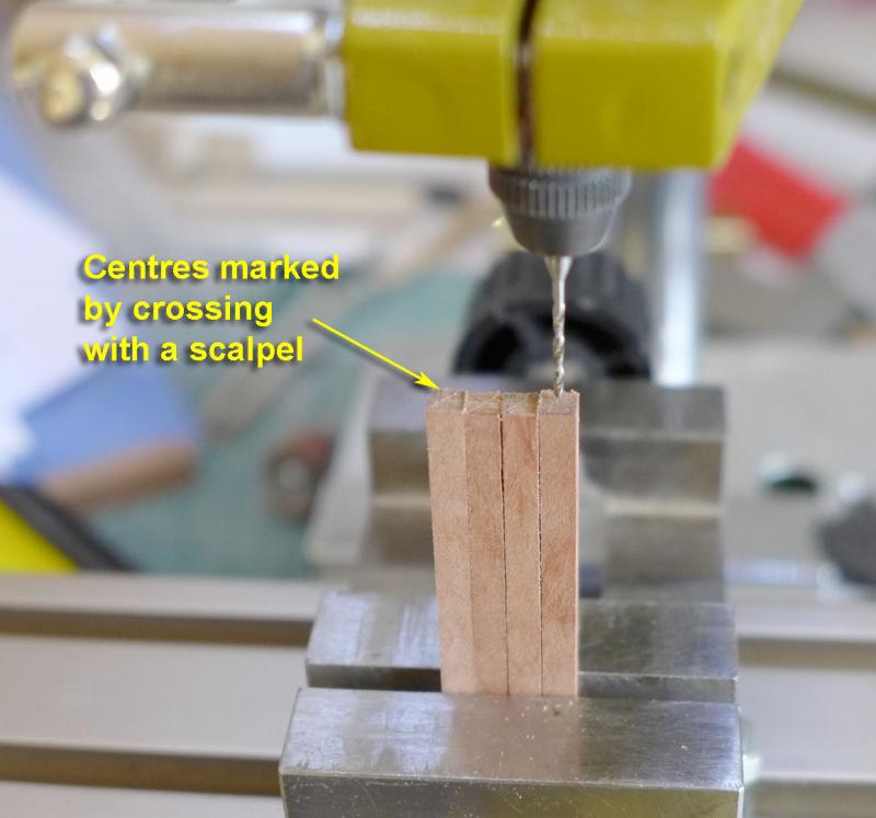
Marking the beams for cutting notches Once the beams were curved correctly, I placed them on the deck clamps and measured the centre points over the keel with a set square. To ensure I replaced them correctly and to allow for variations of width from the centre line, I marked each beam on its upper surface with a ‘P’ and an ‘S’ to mark Port and Starboard. I then took the beams down and marked the positions where cuts were to be made for the carlings and the arms. I had noted that many cut the notches for the carlings while the beams are fixed to the clamps, but I could not figure out a way of doing that which would be accurate. Some of those who build the cross section claim that they cut the notches while the beams are fixed because that allows for the curvature of the beam. However, I thought that simply placing the beam on its side on the plan would allow accurate placement of the cutting marks while compensating for the curvature. Once the beams were roughly marked out, I then clamped them together to ensure that all the marks aligned. The need for lots of practice!!!! Once I’d done this, I realised that making the lattice of beams, carlings and ledges would require considerable practice in cutting notches accurately. So I set to with a scalpel and some mini-chisels I bought off a stall for £3. I used a set of dividers in association with the scalpel to mark the edges of the cuts. You can see some of the practice in the following photo: I quickly learnt: a.) that my chisels needed to be much, much SHARPER! b.) that I’d need to make handles for the chisels to allow me to have a good firm grip. So I went back to the trusty broom handle and fashioned a couple of chisel handles. I then spent a lot of time sharpening the chisels on 600 grit and 1200 grit diamond stones, and boy, did that make a difference!! (For those in the UK who are interested, I bought these from ArcEuroTrade for about £6 each. They really are worth it!) I’m now almost satisfied that I can cut the notches accurately, so I’ll be doing that for the next several days – and probably re-doing them as I make mistakes! Tony


- 132 replies
-
- 12
-
-
- triton cross-section
- cross-section
- (and 1 more)
-
When I was cutting bulkheads by hand, I preferred a jeweller's saw with a very fine blade to the slightly larger type of coping saw you show in the picture. That allowed me to cut really close to the line. As a result, using a drill-driven sanding drum like yours took less time and therefore less noise, but equally demanded really careful handling to avoid over-sanding. However, I found cutting so many pieces by hand tiring and when a nice low-cost re-furbished scroll saw came up on eBay I seized the opportunity and bought it. The sanding issues remain, but it's a whole lot quicker and less tiring now. You might find that it's better to buy a larger drum sander for your drill as you could then rotate it at a lower speed with less noise and greater accuracy. I've been contemplating doing that myself. Tony
-
Thanks again, Mark. I think I'll just go with the half and half idea. I have a feeling I'm being far too obsessional! Tony
-
Thanks, Mark. I also use the drawings direct from the pdfs when cutting, but I just can't see where on the drawings the carlings and ledges are shown in cross-section, i.e. height or depth. I can see length and breadth, but not height. So I assumed half the beam height for carlings (about 2mm) and half the carling height for ledges (about 1mm). I can't see that it matters, but thought I'd ask just in case there is a 'correct' answer. Tony
-
For wood glue, just soak it in isopropyl alchohol (isopropanol). It's easily available at chemists and eBay. I keep a 500ml bottle handy for all the mistakes I make. But you probably don't need to re-do. As has been said, it's just the first planking and sanding and filler does most of the job when mistakes are made. Some people see the first layer of planking as a kind of exercise to get to learn about planking. Tony
- 69 replies
-
- 1
-
-
- lady nelson
- victory models
- (and 1 more)
-
Just a quickie: am I right in assuming that the height of the carlings is about half the height of the beams, and that the height of the ledges is about half that of the carlings? (I'm working on the lower deck, but assume the dimensions would be the same for the gun deck). It's just that I can't see any heights referred to in the plans, and I thought I'd better make sure! If you want to give me the dimensions in full scale inches, that's ok as well! Thanks in advance for any input. Tony
-
I wouldn't be too disheartened at this stage, Patrick. Most of us have had similar experiences and it's likely either to be easy to re-do, or to work around -- especially as this is only the first planking and will be covered up. Photos will help enormously as that will allow others to see where the problem lies and what suggestions or advice to offer. Tony
- 69 replies
-
- 3
-
-
- lady nelson
- victory models
- (and 1 more)
-
How to cut a limber board
tkay11 replied to tkay11's topic in Building, Framing, Planking and plating a ships hull and deck
Thanks, druxey. I had thought about doing it with the saw (as I do have a tilting arbor) and could see how the first face might be cut. However I thought it might be hard to cut the second parallel face over the full length to the exact width as it would require careful juggling with a stick holding it down. And after that I thought that the final flat on the lower surface would prove even more difficult. However, I can see that this might be something to practise and perfect! Tony -
Although I managed to make a limber board for my Triton cross-section, I remain unhappy with the method I used as it wasn't as precise as I wished. The method I used was simply to angle a disc sander and sand the parallel sides without cutting the bottom flat part (I thought that at this scale the lack of a flat part would not be very noticeable). I therefore thought it would be nice to find out from the experts how they approached doing this. The picture of the cross-section is: All contributions most welcome as I'm bound to be doing this on future builds! Thanks Tony

-
Yes indeed, Dirk, I know you'd have started again. In fact I thought of you and Mark when I made my decision. No regrets. None. Not at all. Well, maybe a teeny weeny bit ... I hope you've recovered after your Confederacy agitations. For a moment I thought we might be seeing more of the Sherbourne build. As for your learning about the Triton, well, I reckon most of the others who've done this have lots more to give. I'm still in awe of some of the Triton cross-sections. All the same, thanks a lot for continuing your encouragement -- it means a lot! Tony
- 132 replies
-
- 4
-
-
- triton cross-section
- cross-section
- (and 1 more)
-
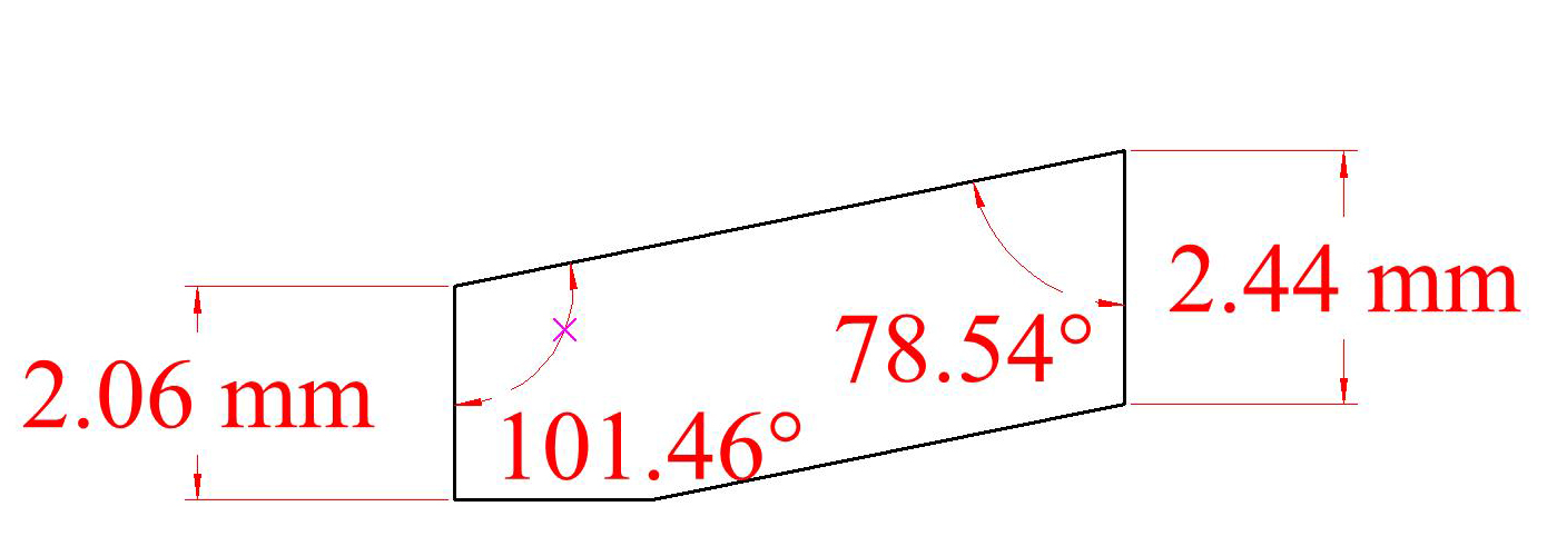
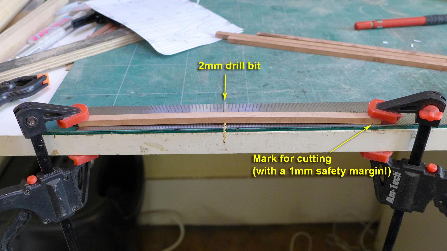
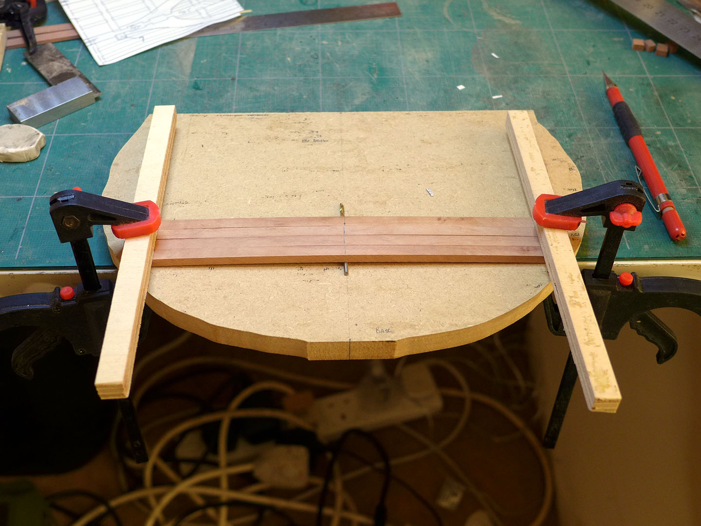
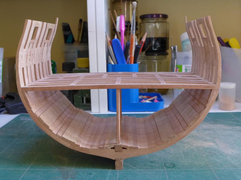
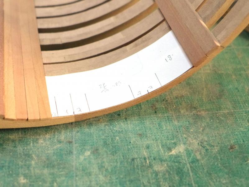
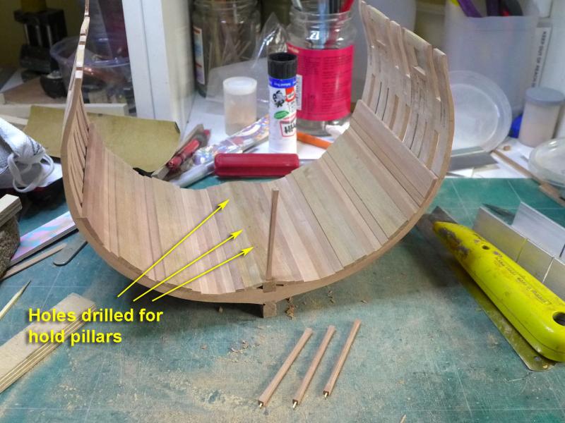
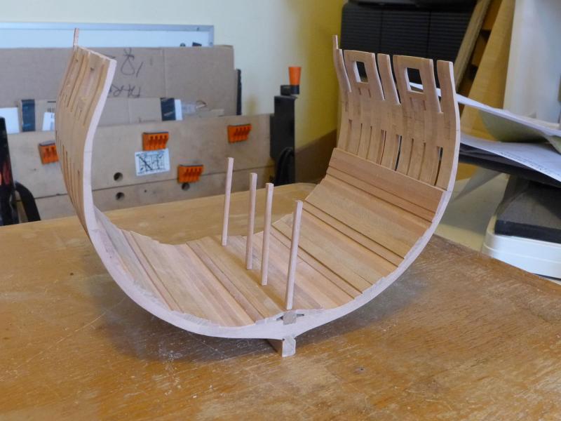
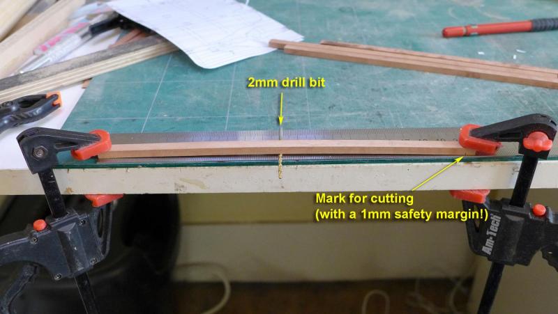
After clarifying for myself what I mean by a ‘learning exercise’ (focus on learning the basic techniques more than attempting a beautiful finish) I decided to continue with the build, albeit with the imperfect frame sanding. Also, as before with my Sherbourne build, I am using this log not only to clarify my own thinking, but also to help other newbies like myself should they come across similar puzzles and questions to the ones I find as the complexities arrive at each stage. Part of this decision was not to make removable limber boards, and to avoid treenails. I thought that doing these precisely is beyond my skill level at present, especially as I’m still struggling with how I might make the angles on the limber boards more precise. Pillars in the hold These I made to scale of 6” square, with a tapered chamfer starting from 8” above the platform and within 6” of the beams as shown by David Antscherl in his book on the fully framed model. Also following his advice, I made 1mm dowels for the pillars and drilled corresponding holes in their bases and on the keelson. (You'll see the finished pillars with the chamfered edges later in this post). Planking After fitting the first 4 strakes outside the limber strakes, I fitted the lower deck clamps. In order to ensure they were at the correct height, I added another platform to my height jig and measured off the height at all four edges. I thought it best to measure out the spaces rather than use the planking shown in the plans, so I used a simple paper template to mark between the lower deck clamps and the bottom strakes. This showed that the thick stuff would not be able to lie exactly over the centre of where the first futtock joins were, although it hit exactly over the centre of the second, upper set of futtock joins. I then checked the setting of the hold pillars Lower deck beams I made up the beams to their actual size (rather than oversize) as I’m bending them with a jig. First of all I measured the width at each beam’s position using an idea from David Antscherl’s book. I then marked the beams for cutting by measuring them after bending them over a 2mm drill bit. The actual height I measured in the CAD programme was 1.97mm, but I thought this would be within the margins of multiple errors. I then transferred the cut beams to the following jig for bending: I am in the process of heating them with a very old hair dryer at occasional intervals over the next few hours until they achieve a stable bend: So the learning process continues, as I am sure it will continue to do so for a very long time! Tony


- 132 replies
-
- 12
-
-
- triton cross-section
- cross-section
- (and 1 more)
-
Tools and techniques used in the 18th Century
tkay11 replied to tkay11's topic in Modeling tools and Workshop Equipment
Another great resource! Thanks a lot, Bob! I've already downloaded and started reading! Tony -
Tools and techniques used in the 18th Century
tkay11 replied to tkay11's topic in Modeling tools and Workshop Equipment
Thanks a lot, Wayne. I'll follow through! Tony -
Tools and techniques used in the 18th Century
tkay11 replied to tkay11's topic in Modeling tools and Workshop Equipment
Very interesting, Wayne, and thanks for the thoughtful reply. What is 'MM' and how do I obtain the articles? Tony