tkay11
-
Posts
1,829 -
Joined
-
Last visited
Content Type
Profiles
Forums
Gallery
Events
Everything posted by tkay11
-
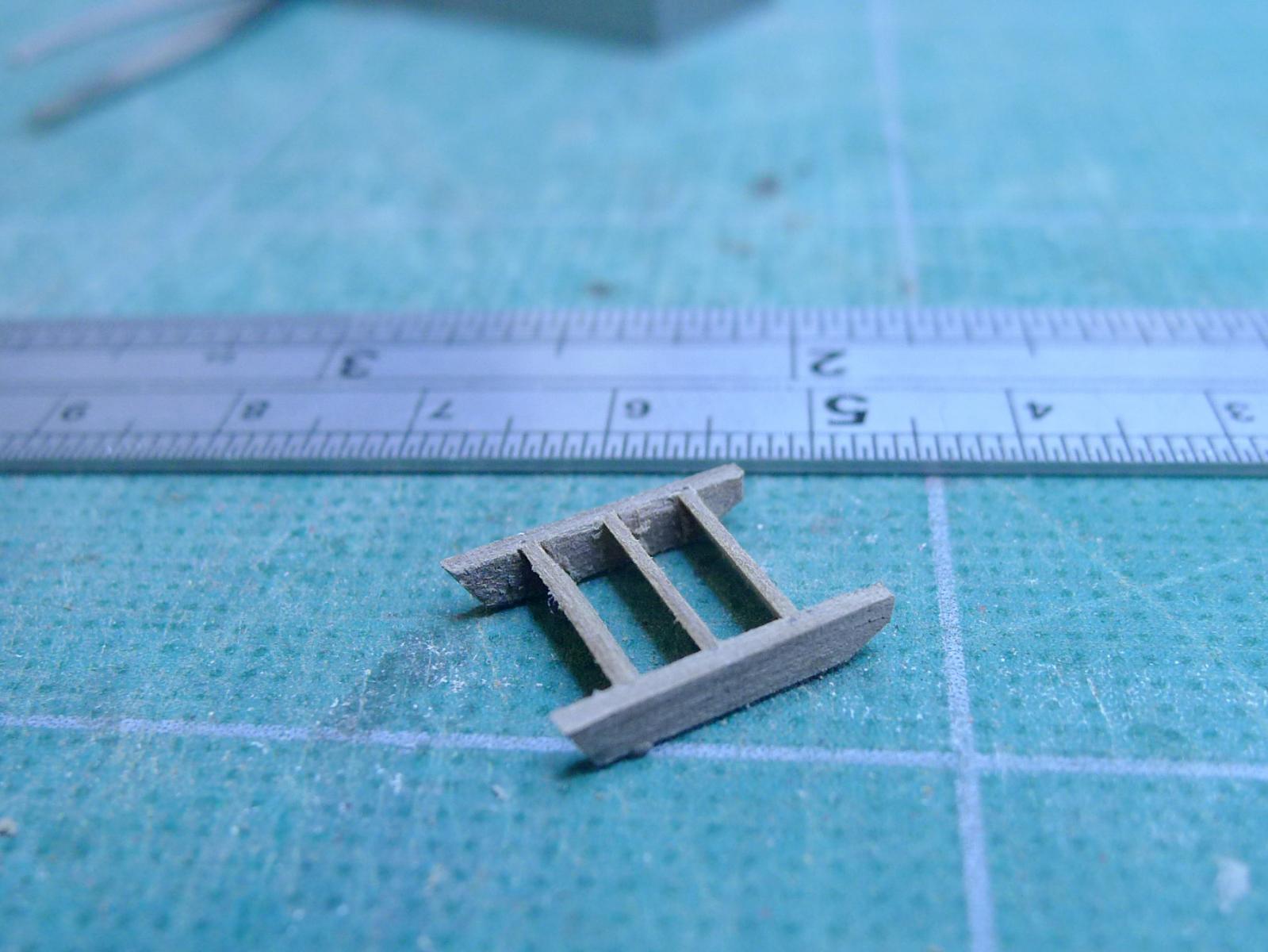
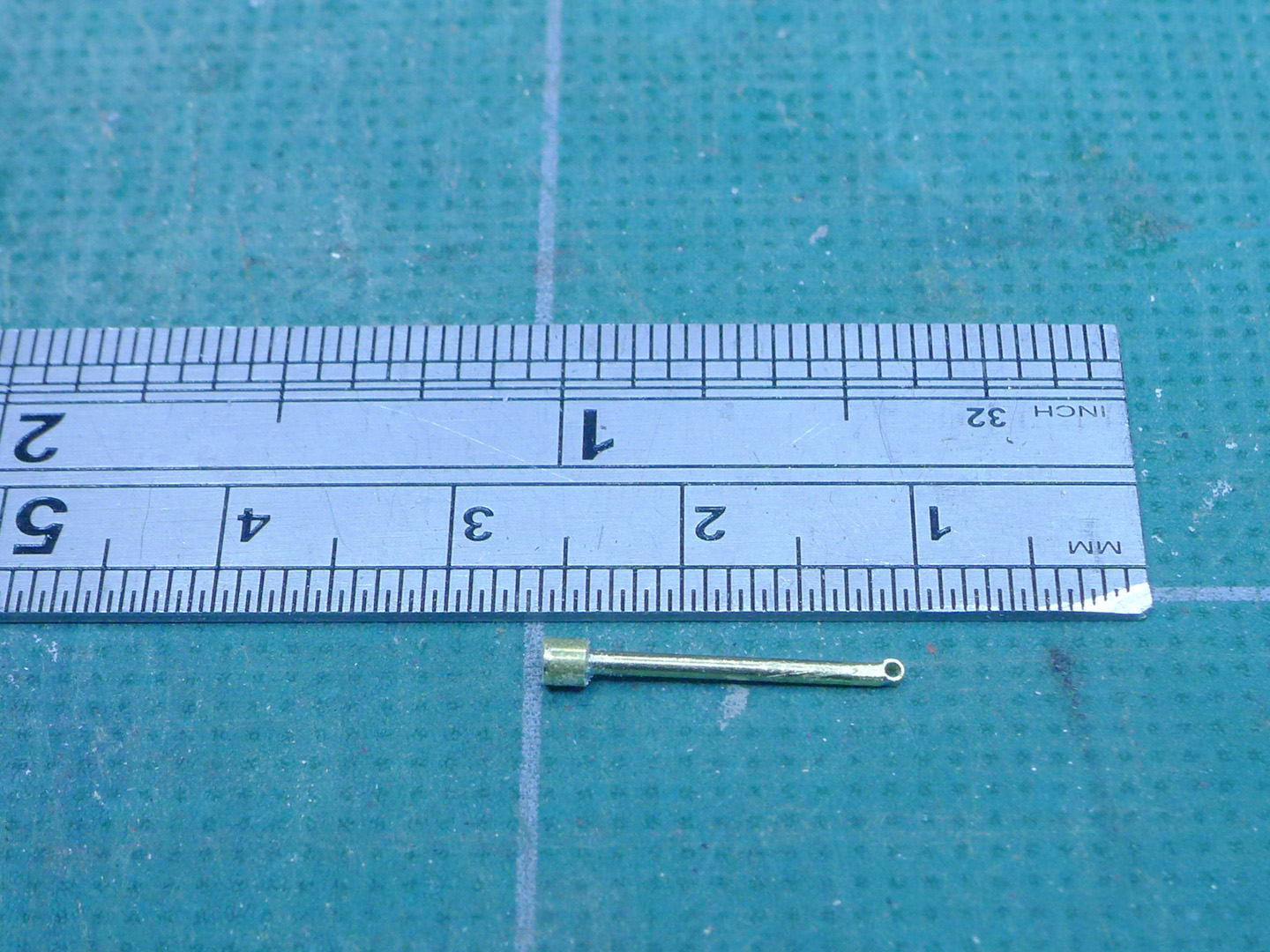
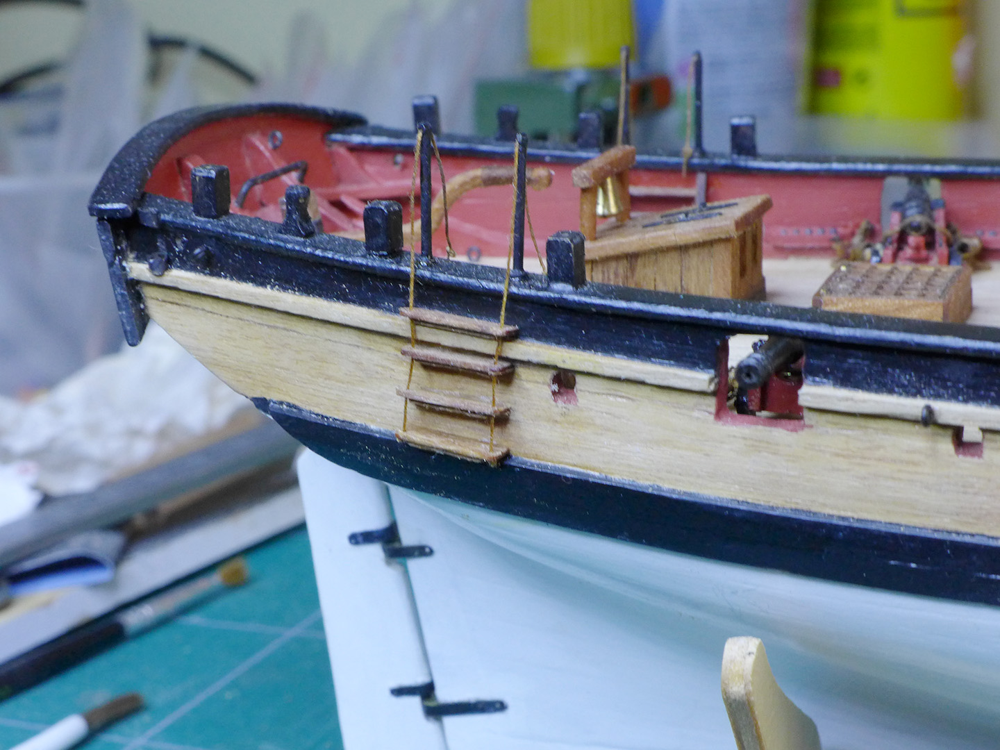
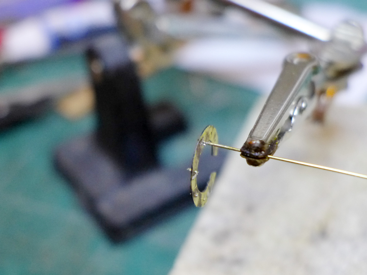
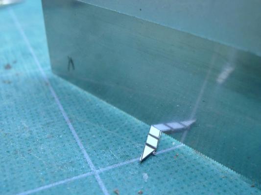
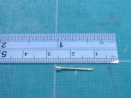
 Entry ladders Next up were the entry ladders. Not much to comment on here (apart from the very crude workmanship which I am afraid marks me well out from all other Sherbourne builders). The inner steps were made by pasting a plan made in TurboCAD onto a strip of wood, then cutting at the correct angle. A razor saw was used to cut the joints for the steps. My first attempt at the stanchions was to turn boxwood on the lathe, but they were rather ungainly compared to brass. So I made the stanchions from a simple brass rod topped by a brass tube which was silver soldered. The base was another brass tube, also silver-soldered. The stanchions were set into the rails.with epoxy adhesive. You’ll note that I decided to put the ropes through the steps rather than letting them hang loose. Tony
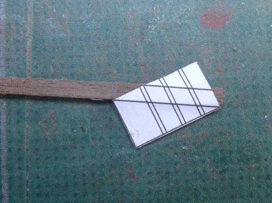


- 269 replies
-
- 8
-

-
- Caldercraft
- First build
- (and 3 more)
-
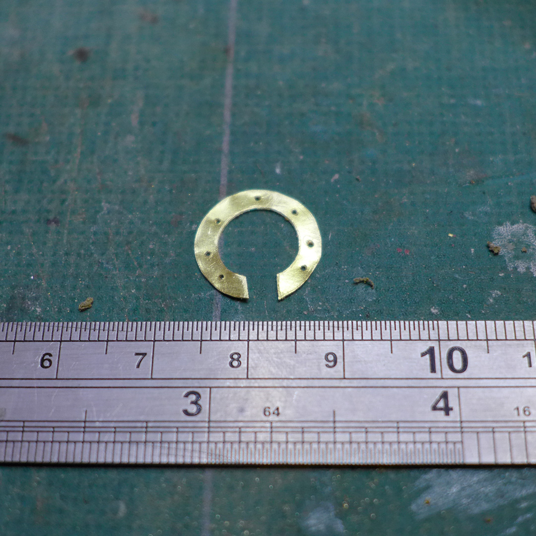
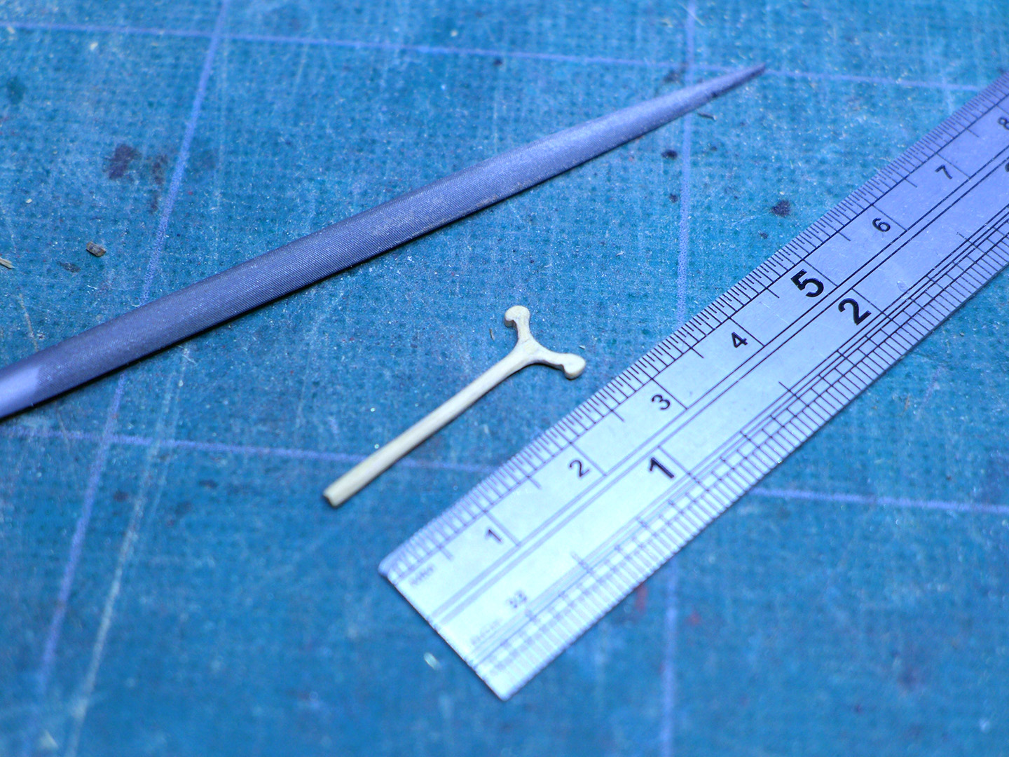
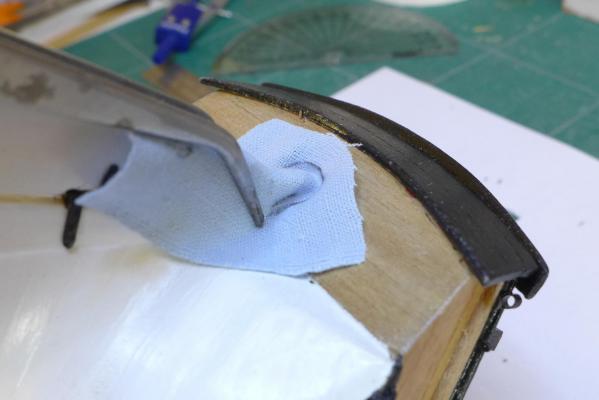
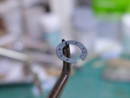
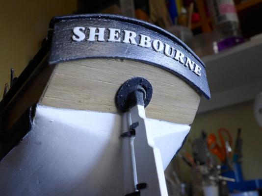
Rudder coat Following many others, I decided I’d try to fix a coat on the rudder. I started by holding some cotton over the rudder and its hole with some self-gripping tweezers. This allowed me to make a rough outline for cutting. I then glued some brass sheet to a strip of wood, and, after drawing the correct diameter circles with a pair of dividers, cut it away with a jeweller’s saw. I then drilled holes for the retaining bolts. Brass rod was then pushed through the holes, silver soldered and cut off flush on one side. On the other side the rods were filed down to an even height to represent the bolt heads. You’ll note I stuck the kit’s letters on the transom for the ship’s name. They’re ugly close up, but at normal viewing distance they’re tolerable. Tiller It was clear that the tiller I had made previously was too long and too low to be usable with the captain’s companionway so close. So I made a new one that was both shorter and s-shaped so that it would be on level with a person’s elbow. Tony


- 269 replies
-
- 9
-
-
- Caldercraft
- First build
- (and 3 more)
-
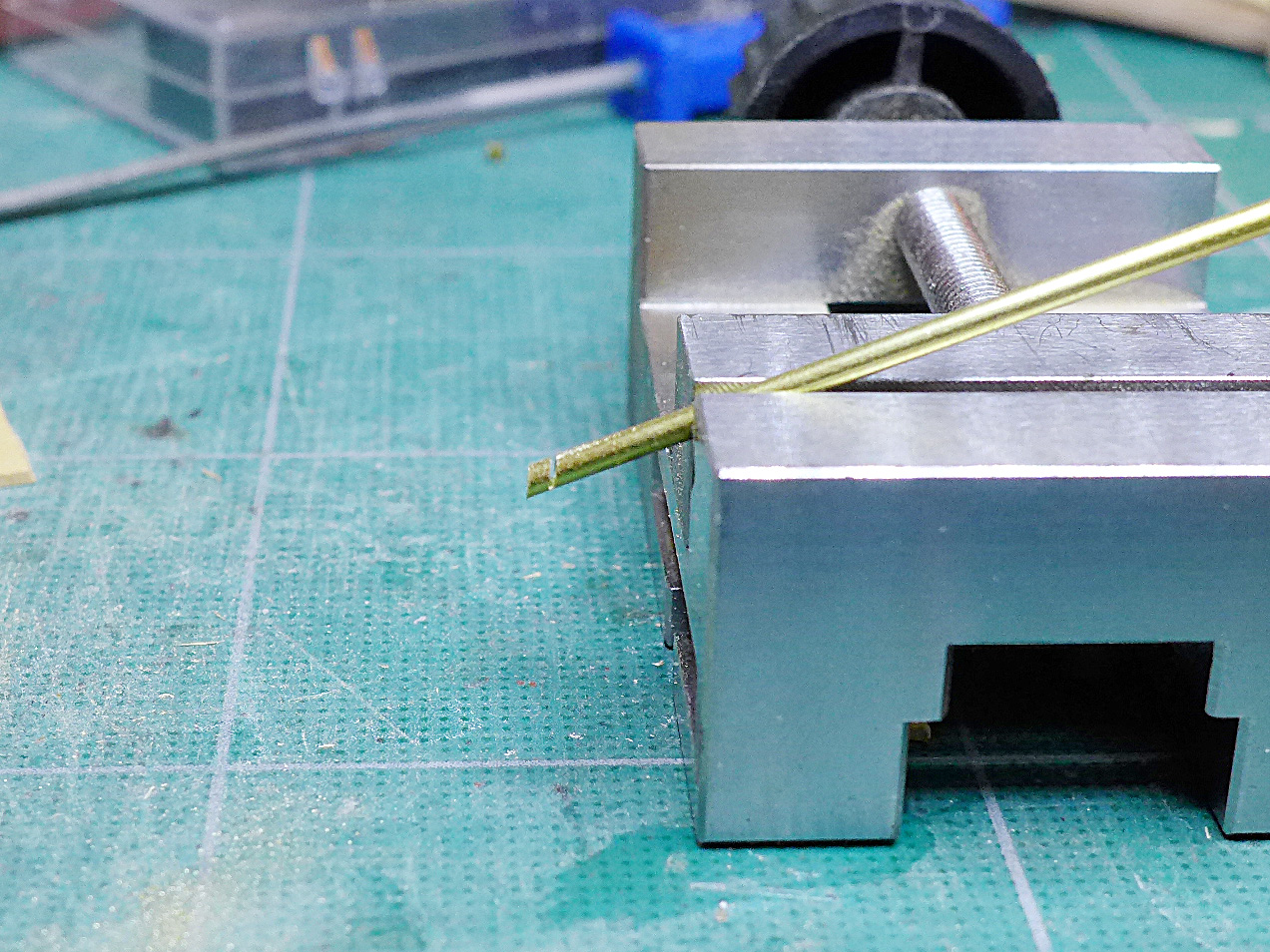
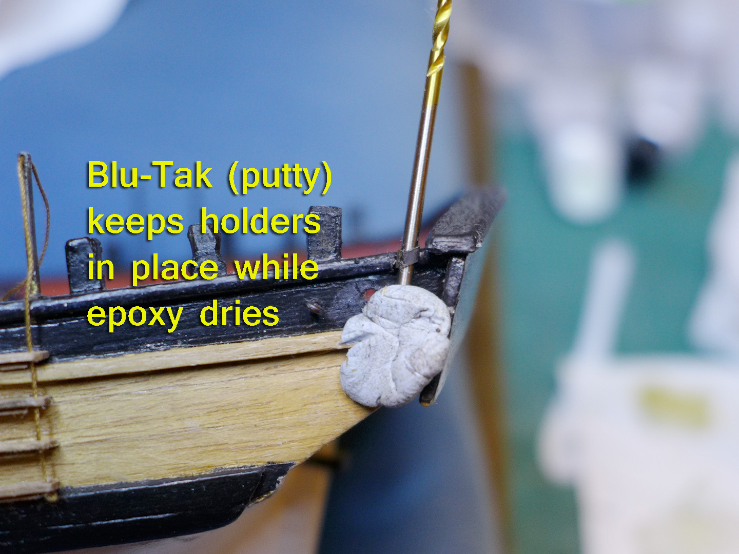
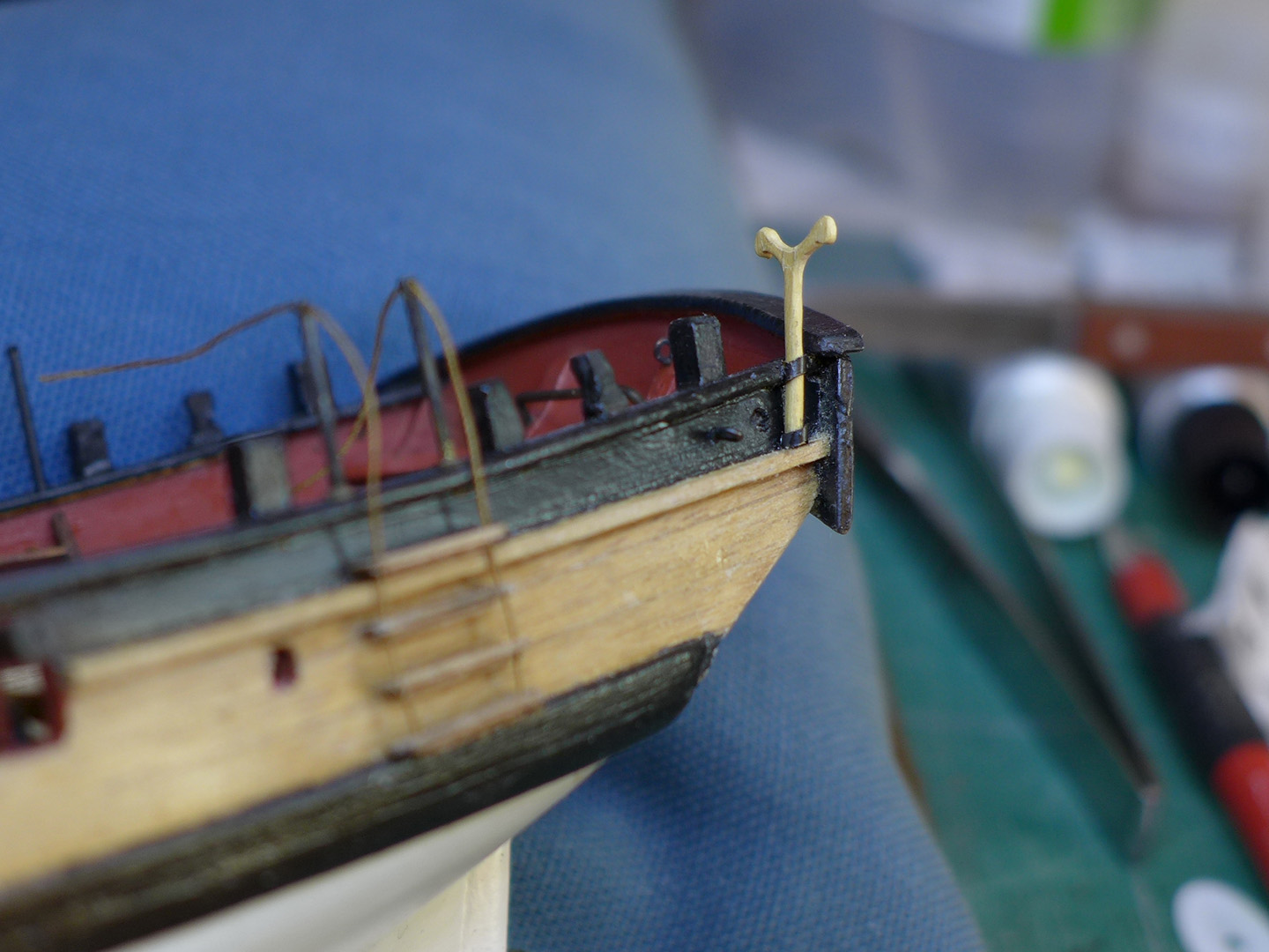
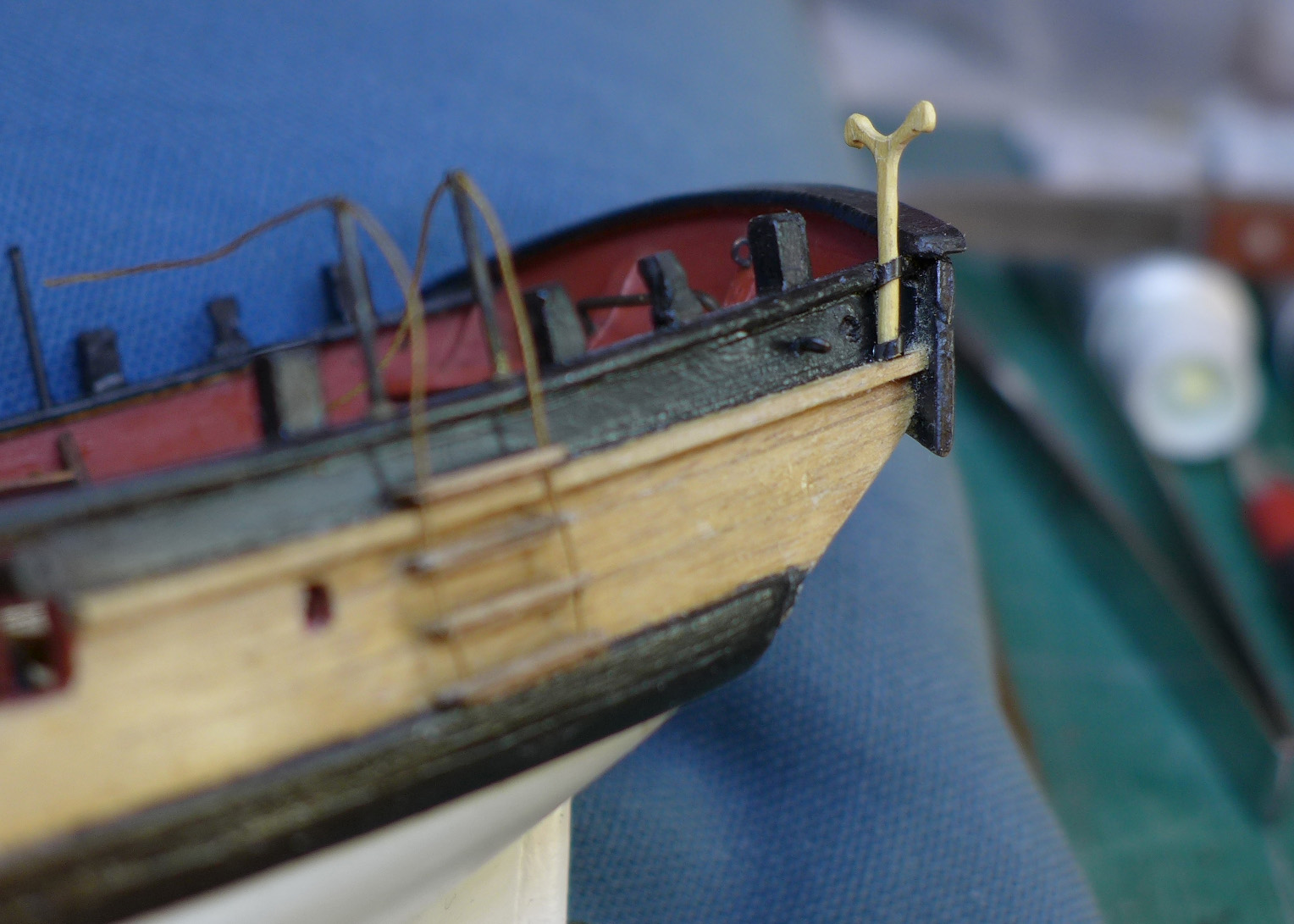
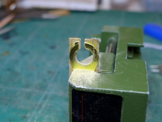
Boom crutchAfter studying the plans, and asking a question about it in the thread ‘Is this a boom support and how is it fitted?’ at http://modelshipworld.com/index.php/topic/7051-is-this-a-boom-support-and-how-is-it-fitted/?p=207835, I decided to make one. At first my idea was to make a stick and add a curved section to the top. This proved impossible. So my next step was to carve it out of a single sheet of pear. I started by drawing an outline to the dimensions shown on the plan. This also proved impossible as the pear simply snapped every time I cut out the outline. However, it worked with boxwood. Then there was the need for holders for the support. Following Chuck’s modelling of the Cheerful, mentioned in the post about boom supports mentioned above, I decided to have holders on either side of the stern, allowing the boom support to be placed on either side according to where it decided to have a little rest when it was tired. I made these holders out of brass tubing. Then glued them to the bulwarks with epoxy and kept them in place with a drill bit and Blu-Tak (a kind of oily putty). Tony


- 269 replies
-
- 6
-
-
- Caldercraft
- First build
- (and 3 more)
-
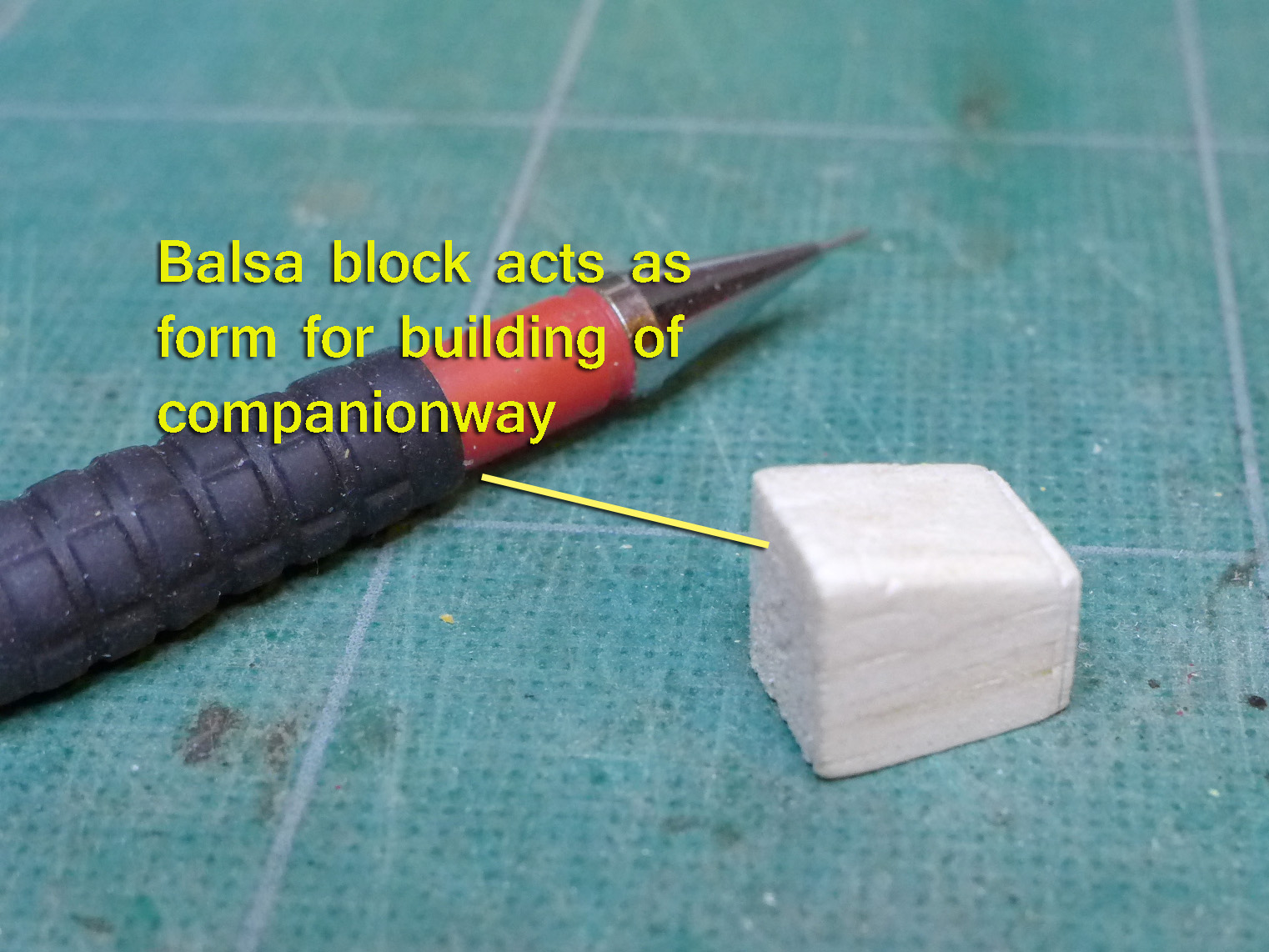
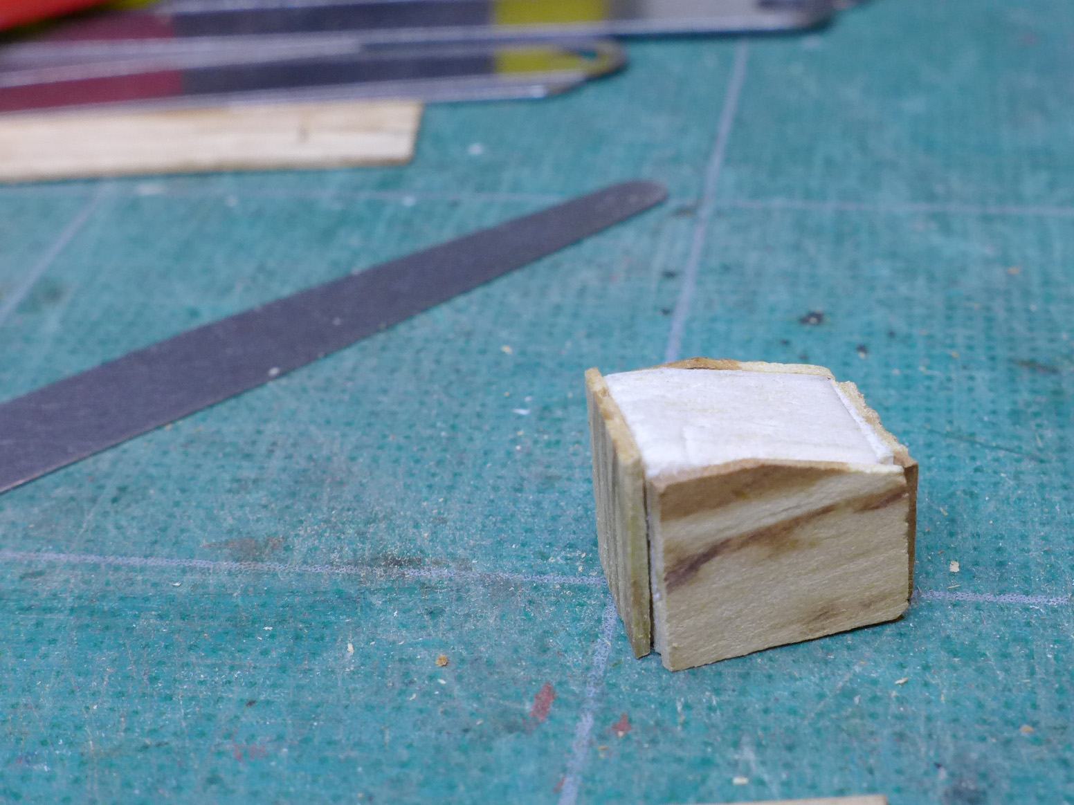
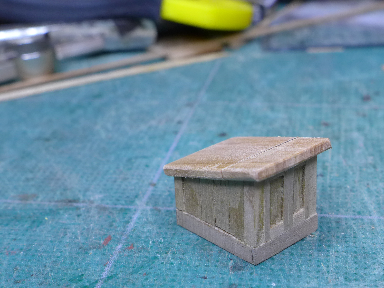
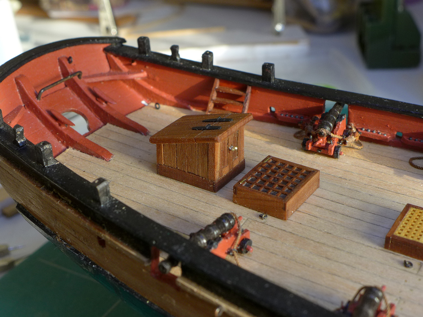
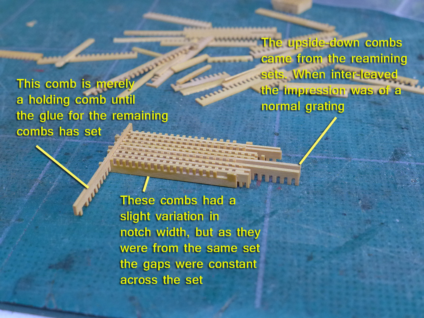
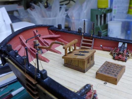
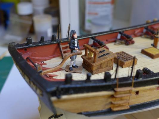
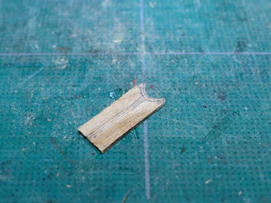
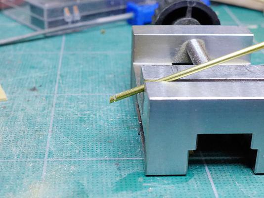
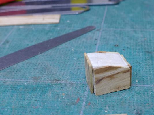
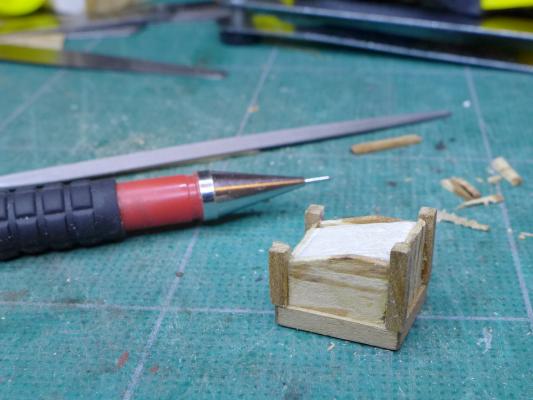
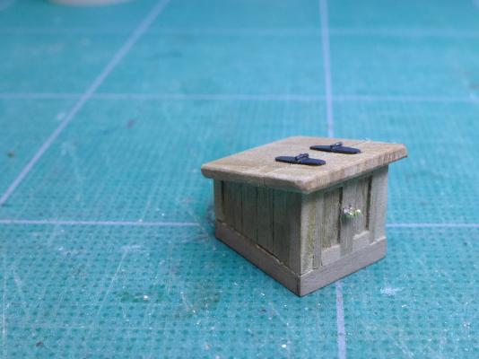
Captain’s companionway I’d been looking at the plans and decided I’d scrap my long companionway, build a captain’s companionway to the height it is in the plans and place it aft, by the tiller. This left me with a dilemma. If I placed the doors of this companionway facing forward, it would leave small room for people moving in and out since the next hatchway is only 2 feet in front. If I had the doors opening to the rear, they would be getting in the way of the tiller. I didn’t think of making them open sideways – partly because the plans show a line on the companionway going side to side, which seemed to me to indicate the roof opening in the fore/aft direction. In the end I decided I’d have the doors opening forwards. I reckoned 2ft was still room to get in and out, and the doors certainly opened comfortably into that space. To build this I drew up some plans in TurboCAD, then made a block from balsa wood to act as the form around which the walls would be placed. I used pear wood from pen blanks that I bought on eBay. The hinges were made of a strip of brass with a 0.5mm brass rod placed across the middle. The whole assembly was then finished with linseed oil. After all that I decided to add the ship’s bell to the roof. This would be in a handy position for whomever was at the tiller. I made the uprights from some pear strips with a wood lathe. The bell I had to buy (an Amati fitting) as I don’t have means of turning brass at the moment. You’ll see the completed bell later in the log in the following posts. Second companionway Although the next hatch forward is shown in the plans as a normal hatch, I couldn’t resist keeping the glass-covered companionway I had previously made to fit this position. I had put so much effort into building it that I decided to give those down below light as well as some protection from the elements. Naughty but nice. Remaining hatches re-made This left the remaining hatches aft and fore of the main hatch. I had made them with the kit gratings, but since I had remade the main hatch with much smaller gratings to be in line with the likely real size, the small hatches looked incongruous. So I remade those using some of the combs I had not used in making the main hatch. In doing this I stumbled across a very handy little ploy that overcame the fact that some of the combs were not evenly spaced – several of them had slightly widening gaps as they moved along the comb as a result of my not being too careful with the saw. However, by taking the combs in the batches from which they were originally cut, I could then just interleave the remaining combs upside down and the overall appearance was of a correctly-spaced grating. The assembly was then covered with dilute PVA, cut to size and placed in coamings. You will see the pictures of these remaining hatches later in the build log where other aspects of the deck furniture are shown. Tony


- 269 replies
-
- 6
-
-
- Caldercraft
- First build
- (and 3 more)
-
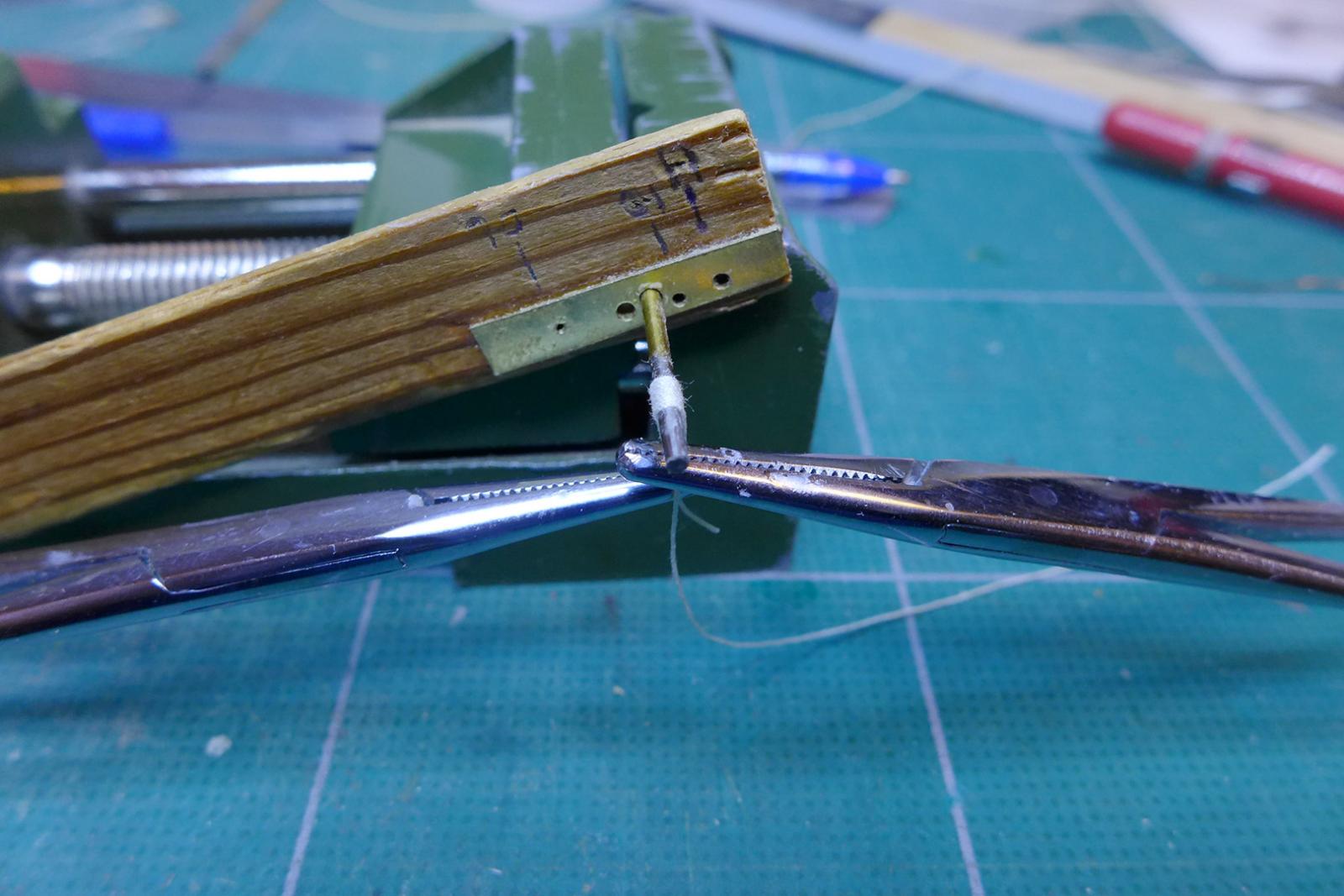
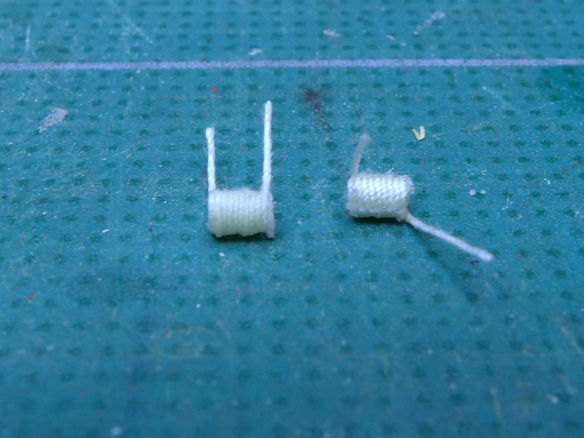
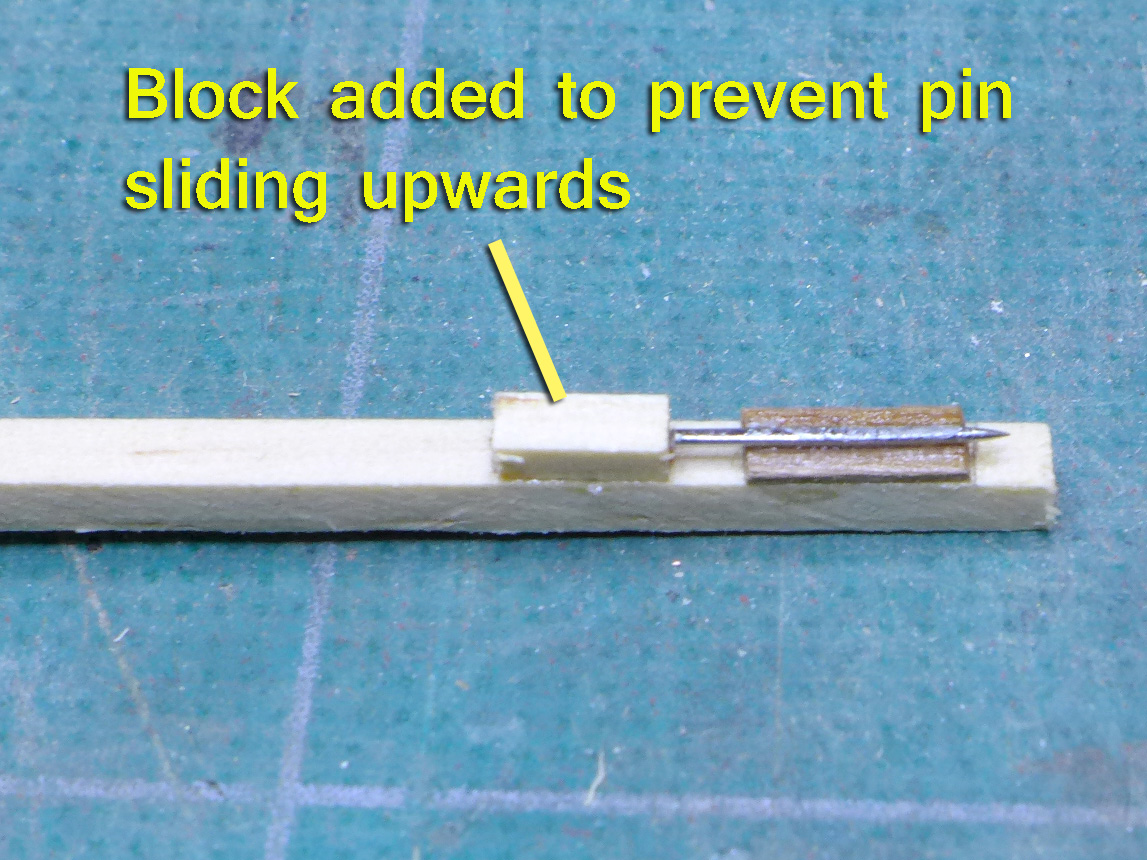
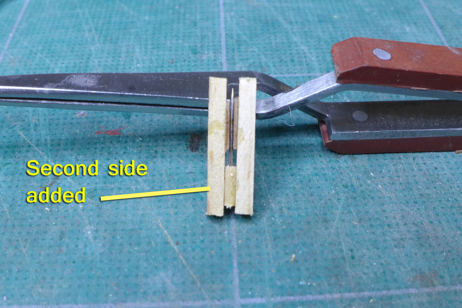
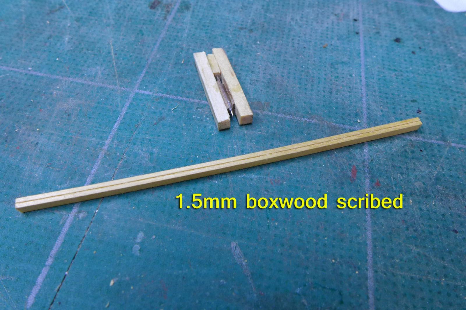
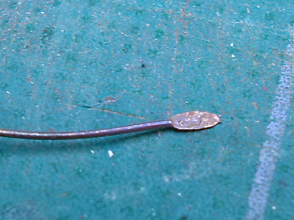
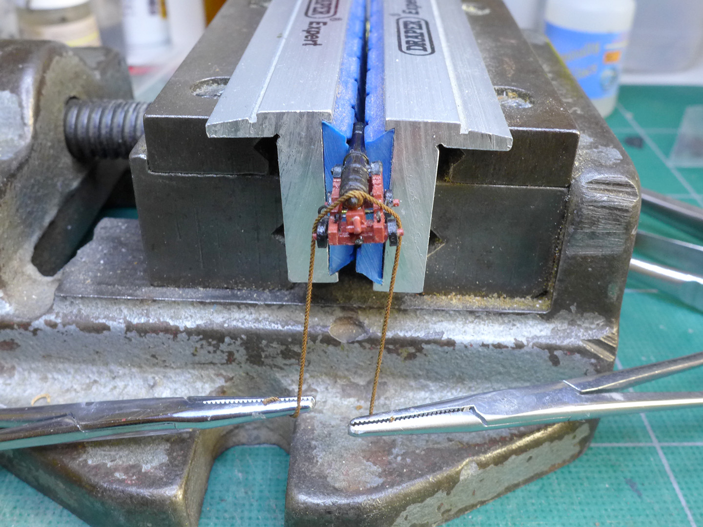
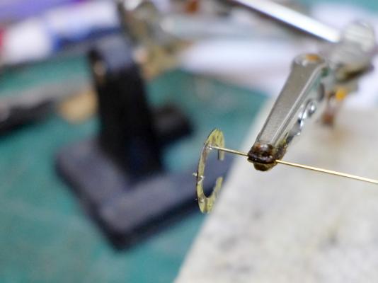
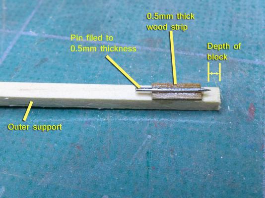
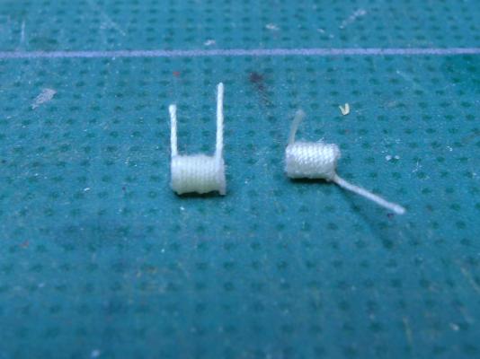
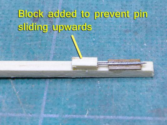
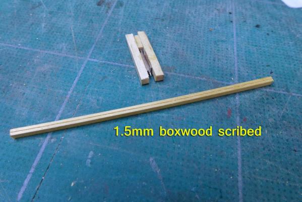
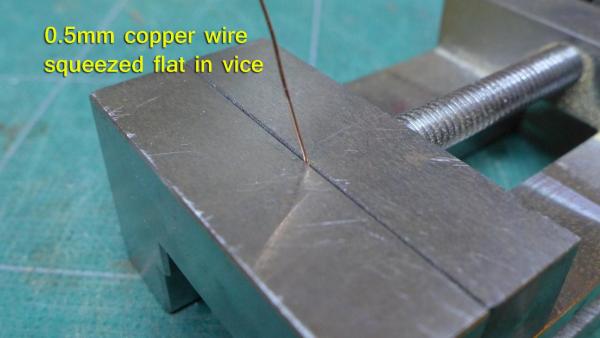
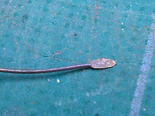
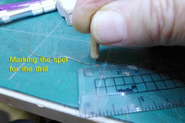
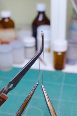
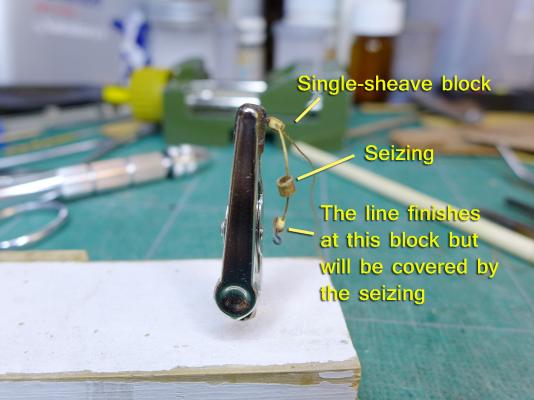
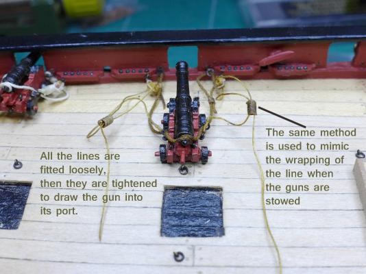
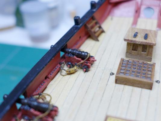
Cannon 1. Shot The first problem resulting from my making the cannon to the scale of 3-pounders was that the shot I had put in the shot racks was clearly too large. So I searched around for 1mm shot that could be painted black. Black plastic ones guaranteed to be exactly 1mm are very expensive. Steel ball bearings proved useless as I couldn’t get them to take black. I ended up getting 200gm of 1mm steel carbon pellets from eBay. It’s the type that’s used to fill soft toys. It turned out that the stated 1mm was a bit variable, so although the shot is now roughly the right size, I failed in achieving symmetry of placement in the shot racks (which also had to be re-made – as you’ll notice in several of the pictures in the rest of the log, which appears over the next few postings). I now realise I didn’t try gun blue on the steel ball bearings, so that may be worth a try in future. 2. Seizings For the rigging of the cannon, first thing to do was prepare the seizings. In this I followed the idea from the late Hubert Sicard in wrapping line around a drill bit and holding it in place with two forceps/haemostats whilst glue was applied. The drill bit was coated with beeswax for each seizing made. I used CA glue at first but eventually shifted to using diluted PVA glue which is far kinder to the thread, leaves it a bit flexible, takes up stain, and does not discolour the thread. 3. Blocks Again because of the smaller size of the guns, I found that the blocks with their hooks I had originally made were too long to fit between the rear-most eye on the side of the cannon and the eye in the bulwark. Furthermore, if I stuck with the double-sheaved blocks, the smallest I could make them to take 0.25mm thread made them still seem enormously wide compared to the guns. This posed quite a challenge which I tried to get round in two ways: a. using only one single-sheaved block attached to the bulwark. This I justified in thinking that the lighter cannon might have been pulled back using only a single sheave pulley. I also thought of using one block only, with a line going straight to the hook that attached to the rear of the gun carriage. I reckoned that when I wrapped the line round the blocks it would be hard to tell that there were one or two blocks there at all. This was the first approach I used and did this for all 8 cannon. This is similar to the approach that some people use. Thus George Bandurek put two blocks on a wire and wrapped the line around the whole assembly. Others have carved a small length of wood to the dimensions of two blocks linked by their ropes and then wrapped line around that. However, although that was relatively successful, I reckoned I should have another try at doing it in keeping with the proper rigging. b. So I tried making the blocks and hooks even smaller. I stuck to the idea of having single-sheaved blocks, but this still required several stages. The first was to find a way of marking the blocks out. I followed Frolich’s suggestion of making a scribe. At first I couldn’t think how to do it as he seemed to suggest just sticking pins in wood, and the smallest pins I could find were too wide to be used as scribes with a depth stop. Eventually I cottoned on: I filed down the sides of the pins until they were the correct width for the sheave and then sandwich them between leaves of wood against an end stop. You’ll see the process in the following pictures. With the smaller block came the need for a smaller hook. I squeezed a 0.4mm piece of copper wire in a vice, then drilled a 0.3mm hole through the flattened end. Finished off by curving the remaining wire to a hook shape and cutting off. I could now strop the blocks. At last I could rig the cannon. First the breeching tackle. This I made up to 0.5mm diameter using the ropewalk I had made from an old shaver. Then the ropes could all be attached. Note that I dyed the lines with walnut dye first. The lines are attached to the bulwarks and the cannon, but left loose. This allows the lines then to be tightened until the gun is firmly against the bulwark, at which point it is glued to the deck. Note also that I allowed the line in the rearmost block to terminate at that block, rather than link it to the foremost block. This was simply because that line would not be seen when the blocks were wrapped for stowage. Tony


- 269 replies
-
- 5
-
-
- Caldercraft
- First build
- (and 3 more)
-
Thanks, Kester. I probably just need more experience with stains! Anyway, I also need experience with different woods, so I am not going to be too upset at forking out for the pear. It'll come in handy for my next build should I ever get to it. Tony
-
Lovely work as usual, Kester! I'm glad you, Gregor and Dirk are so far ahead that I can keep on picking up tips. I like the finish on your mast. Did you use the kit wood and stain, or is it different wood? And if it's stained, how did you do it? I tried staining mine with all sorts of finishes (walnut stain, oak dye, linseed oil, incredibly thick tea (with and without ferric acetate made from steel wool and white vinegar) -- but they all came out blotchy, no matter how many applications. I've ended up ordering pear for the mast, boom, spars and bowsprit. I saw Gregor used maple for his bowsprit. Tony
-
Thanks very much, Gregor. I must remember to look at zu Mondfeld's book more often and more thoroughly! I'm still on the bowsprit. I was clinging on to the idea that I could stain the kit wood. After various experiments, including dyes, stains and tea (with and without using steel wool dissolved in white vinegar/acetic acid), as well as finishing with linseed oil, I have finally decided that I can't continue with the kit wood nor with birch dowel as both simply are too blotchy (or too light in comparison with the rest of the wood on the ship) with whatever combination I have tried. So I have just ordered some pear. So there's plenty of time yet before I get to the shrouds -- and I am going to rebuild my ropewalk and make a serving machine before doing that. I was happy, though, to experiment with putting a sheave in the bowsprit. That went really well. So I'm ready now for the final version. Oh -- the reason I haven't been doing my log is that I wanted to get all the different deck fittings finalised and in harmony before posting. I have been through so many iterations of windlass, belaying pin racks etc that I thought it would be silly to post and then show all the undoings and redoings. Tony
-
I really like the acrylic sea. A most pleasurable build to have followed. Many thanks! Tony
- 226 replies
-
- 1
-
-
- ballahoo
- caldercraft
- (and 1 more)
-
Nice work! just wondering how you blackened the ball bearings, or were they black already? I tried steel ball bearings for my own 1/64 model, but couldn't blacken them. Ended up using 1mm shot which unfortunately was variable in size. Others have used coloured plastic balls, but they are very expensive. Tony
-
Thanks a lot, Gregor. I like the fact that you did add a pin rail, but immediately behind the stem. Very crafty (I hadn't noticed it before). I'll now study this and come to grips with it all. As to the windlass -- yours is definitely better than mine, but I've much enjoyed making it. I see that the blocks holding it to the bulkheads don't reach the deck in your model -- in mine they drop to the deck, but I wasn't sure about it. I'll leave mine as is. I'll start posting all the updates on my build soon, but there'll be little interest for you. The main differences are: (1) my boom crutch -- I've placed holders for the crutch on either side of the the stern -- as a result of Chuck's Cheerful. (2) I've threaded the ropes for the steps into the ship through the steps themselves. (3) You'll also see the compromises in rigging the gun tackles I tried as a result of the 3-pounder carriages being smaller. (4) I altered the rear companionway to be in line with the plans, and added the ship's bell to its top. (5) I've shortened the tiller considerably and given it an S shape (because of the position of the companionway on the plans). (5) I've left out the fife rail in front of the mast and left room instead for the galley pipe). Thanks again for the considerable help and advice you continue to give! Tony
-
I've been going over your log yet again, Gregor, and now that I'm almost ready to start the bowsprit and the rigging, I have an intense interest in the belaying plan. You have said you considerably modified your old belaying plan, so I am wondering how you have changed it. In particular I would like to know how you have placed the points for the jib inhaul and outhaul, the topsail yard braces, the foresail downhaul and the lower yard counter-braces -- all of which have the special belaying rack forward of the windlass on Petersson's plan. Now that I have made a windlass along the lines of yours (i.e. as per the original plan), the only option would be to attach a rail on either side of the pawl if I were to continue with Petersson's idea. However that would mean a real crowding of the deck space between the pawl and the stem. As a result I am trying to cut searching in the darkness of my lack of knowledge and understanding, and instead asking for the simple solution that I am sure you would have found! As usual, I'll be very grateful of any ideas! Tony
-
I have the Phantom practicum as a pdf file. I don't seem to be able to attach it to this post so I've uploaded to DropBox at this location. If Chuck or anyone wants to put it in the forum space they're welcome. I'll remove it from DropBox in a week or so. Tony
-
I've collated all the 77 videos available on YouTube of the Australians' visit to Dr. Mike. The complete list (with the titles in Russian) is at https://www.youtube.com/playlist?list=PL5wX2_PJGI8sxN_zzXNTWaZ9qi-U_9Zp7 I've used Google translate to compile the list in English with links but I find I can't paste the sheet without losing the formatting, and I don't seem to be permitted to attach Word or Excel files. So if anyone wants this list, you can download either the Excel or Word files from DropBox at https://www.dropbox.com/sh/rx2ygepydpn2kja/AAD5j9X6QiKpQp_MhWU4Fcxla?dl=0 Tony
-
Useful tip, Gregor! I'll make sure I have the bobstay installed strongly before getting on to the main mast. I'm shortly to start work on the bowsprit, having almost completed the deck (I'm working on doing the windlass as a hexagonal one as per the original plan and your own model -- an idea which may or may not come to fruition). Thanks Tony
-
Thanks, druxey. In fact I've fitted both a horse and a crutch. I followed Chuck's idea of two crutches in the sense that I placed holding rings for the crutch on both sides of the ship, but just one crutch which can be removed and placed on either side depending on which side the boom feels like resting when it's hanging around in port. This also means that it can be stowed away quite easily when not in use. I have no idea whether this is accurate historically, but it would have made sense if so (I think!). The crutch in the photo is plain boxwood at the moment, but I'm trying to figure out how best to stain it as my walnut stain seems to give a blotchy appearance on boxwood at the moment. You can see the horse just out of focus in the background. Tony

-
Thanks, Christian. Sorry to have pushed this off topic. 0.1mm is what I can do as well with my Proxxon saw, and I'd expect that from a supplier. My feeler gauges are in 0.1mm increments. That's why I put the column for expected cutting tolerance on the right in my post #232 above to one decimal place, or 0.1mm. The differences from the conversion appear small, but I was worried that over a long distance between bulkheads or for the planking or, as Chuck says, between bulkheads and former, those small differences might make a problem. I have become used to seeing differences of less than 0.1mm on my own model, but that is at 1/64 scale, and it might be less problematic at 1/48. As a complete novice and having no experience at all of how it might play out I thought I'd still ask. However, Chuck has given me the solid advice: "Following the plans will do the trick...when you adjust any wood sizes...think about what you will need to adjust on the plans....but it may not even be needed". And as Nigel has said, in the UK, at least, there is still stuff off the shelves in inches. Apologies to Chuck for posting on his log -- I just thought this discussion might be useful for Europeans and others who work in metric as well and who are intensely interested in this great project. Tony
- 1,051 replies
-
- 4
-
-
- cheerful
- Syren Ship Model Company
- (and 1 more)
-
And of course if the planks are too thick that allows for good sanding! Very grateful, as always, for your help and thoughts. Tony
- 1,051 replies
-
- 1
-
-
- cheerful
- Syren Ship Model Company
- (and 1 more)
-
Thanks, Chuck. I don't think I was expecting you to do the conversions! It's amazing that you are doing all the work you do -- let alone re-adjust your whole plan to accommodate a question like this! I was just wondering how we'd do it in practice. I know it is a simple matter of multiplying by 25.4. I think I was just asking that if we did have it in mm, or since my saw is calibrated in mm, whether cutting to the nearest single decimal point would have enough cumulative tolerance over long distances to have no problems in building. The following is the conversion for the sizes you posted which shows the very slight differences if I was to ask for cuts in mm, or to cut it myself: ins dec ins mm nearest mm for cutting purposes 0.025 0.025 0.635 0.6 1/32 0.03125 0.79375 0.8 1/16 0.0625 1.5875 1.6 3/32 0.09375 2.38125 2.4 1/8 0.125 3.175 3.2 5/32 0.15625 3.96875 4.0 3/16 0.1875 4.7625 4.8 7/32 0.21875 5.55625 5.6 1/4 0.25 6.35 6.4 3/8 0.375 9.525 9.5 I think the best thing for me will be to wait till I get the plans. I can then estimate whether these slight differences will accumulate or not. I can see that it might well be possible and easier to order wood cut to inches, so I'll have to find out. Although currently I have no concept of what quarters, eighths sixteenths and thirty-seconds look like, it'll be good for me to learn, given that so many plans that are available are in inches and feet. Sorry for asking again, and thanks for taking the time to respond. Tony
- 1,051 replies
-
- 4
-
-
- cheerful
- Syren Ship Model Company
- (and 1 more)
-
Chuck, I'm sorry to ask this again, but looking at your list of wood sizes ordered, they are all in inches and fractions of inches and I'm having another wobbly. In the UK I'd be ordering thicknesses of wood in millimetres. If you just have one layer of planking, and we stick to the plans, wouldn't that make the thickness rather crucial? Similarly, if the bulkheads, or frames, are given a certain spacing, wouldn't that have some impact on the length and/or the positioning of cut-outs for ports etc? In my own amateurish build of the Sherbourne, the instructions and plans were based on 1mm thicknesses of planks. Without thinking too much about it, I did the 2nd layer of planking with 0.5mm wood. This led to a difficulty when it came to matching the thickness to the wales (although I can't quite remember what that difficulty was since I obviously managed somehow!). I also can imagine that changing the thickness of the bulkheads and the keel from inches to mm might end up in some confusion. We can't order in fractions of a millimetre, although we can order 0.5 and 0.6mm fairly easily. So when we look at the plans, how would we factor in the necessary conversions? Are the plans giving original measurements or do you think that the differences would be so small as not to make any difference to the construction at this scale? I really hope I am not missing something blindingly obvious here, but I seem to remember a discussion in MSW 1.0 about problems of converting plans from inches to metric. I think this involved the sizes of the frames rather than anything else. Please ignore and allow others to berate me if I am really being dense! This may be one of those occasions when the dislike button can be pressed! Tony
-
Chuck, this may be a daft question, but for those of us that work in metric, will there be any problem when it comes to using your plans to build our own Cheerfuls? Tony
- 1,051 replies
-
- 3
-
-
- cheerful
- Syren Ship Model Company
- (and 1 more)
-
Thanks very much, Gregor, that helps a lot! Nicely made! Tony
-
Well, it looks great to me! But I'm nowhere near starting the rigging yet as I'm still debating the placement of the aft companionway, its direction and its height. So I look forward to hearing when or if you change the arrangements round blocks for the jib halliard. I'm interested in the boom crutch you've placed at the centre of the transom. I'm trying to fashion one out of wood at the moment, and I was thinking of putting it into a socket that is replicated on port and starboard as the plans suggest that kind of placement to me. Is yours made from brass (something I've also considered)? It would be nice if you could post a picture showing its placement and say how you made it, as I might change my own plans as a result! Thanks again for demonstrating (as have Kester and Dirk) the potential of this nice kit. Tony
-
Thanks, Kester, for continuing to explain what you do, why, and how you do it -- great tips for the likes of myself, and a lovely build to boot. Tony
-
Thanks, Kester, and good points. It's nice that putting your ship's boat above the main hatch also hides the other hatches to some extent, and because it is a lovely model in its own right distracts from pedantic probing (such as mine) as to the plans! If I were to place my own ship's boat in the same position it would, on the other hand, draw attention to its crude build. Ah well, stuff to ponder on -- along with all the other pondering I am up to at the same time concerning other aspects of the model. It's gradually coming together, though. Tony
- 6 replies
-
- 1
-
-
- Sherbourne
- tiller
- (and 1 more)