EJ_L
-
Posts
2,246 -
Joined
-
Last visited
Content Type
Profiles
Forums
Gallery
Events
Everything posted by EJ_L
-
 A huge congratulations on a well built model! I've enjoyed following along on this build and indeed it has been very inspirational to my own RL build. Display her proudly, (once you get that help to mover her to a case) and I look forward to watching your next build!
- 786 replies
-
- 3
-

-
- Royal Louis
- Finished
- (and 1 more)
-
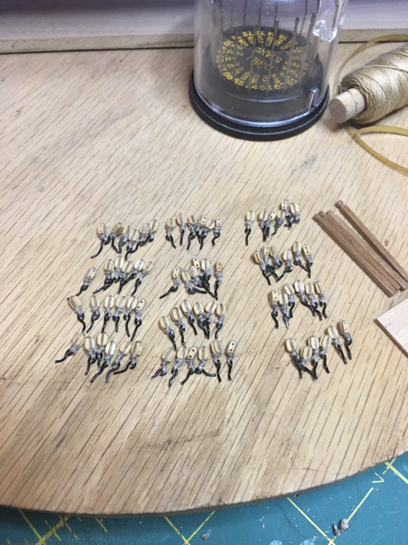
Work is slow right now on the ship, lots of life things getting in the way, but I am still getting some stuff done. Stropping blocks for the gun tackle. These are going on the upper gun deck where they are exposed in the waist.
-
I cannot be certain that S.o.t.S. was this way, but my understanding is that the forward chase cannons and the two foremost broadside cannons were the same gun just shifted to different ports as needed. The reason is that with the foremost broadside guns in place, there is no room for the chase cannons to recoil or be returned inboard to reload. Looking at the picture of all of your chase guns in place, the outer two chase guns would recoil into the leading broadsides. Depending upon how you want to display her, you could leave them all in place as it is much more dramatic, (I have done this on mine) despite functional accuracy. My other suggestion would be to leave the two foremost broadsides out and have all four chase guns in place. This arrangement while more accurate also adds two view ports to see some of the details under the forecastle. I am honestly uncertain as to how the cathead arrangement works on this vessel. Very curious though.
-
I love this display! Phenomenal job! The amount of detail you have worked in to this model is amazing and the quality top notch. I can, (and do) spend a lot of time looking at each picture taking it all in. I've said it before, a true inspiration!
-
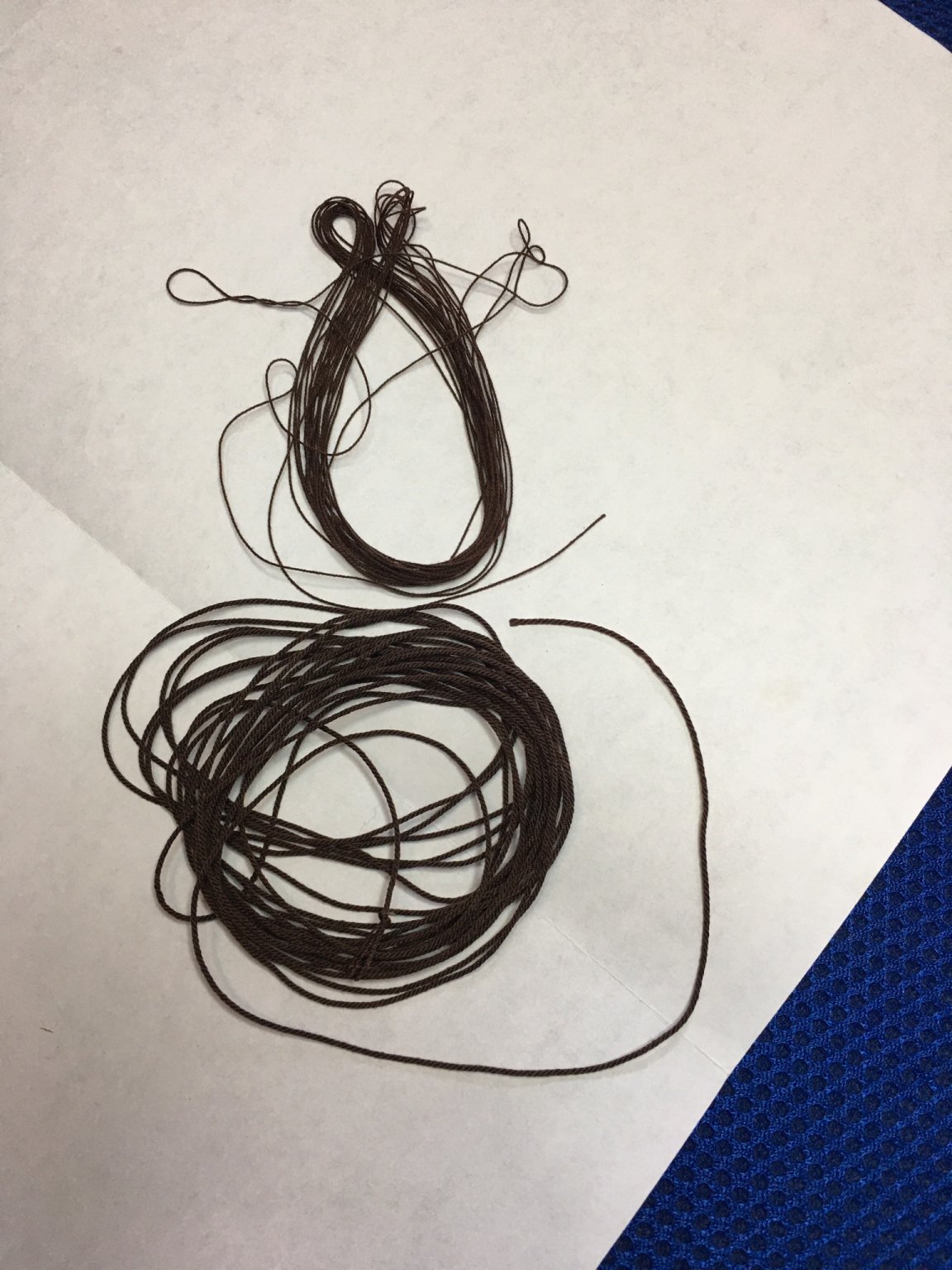
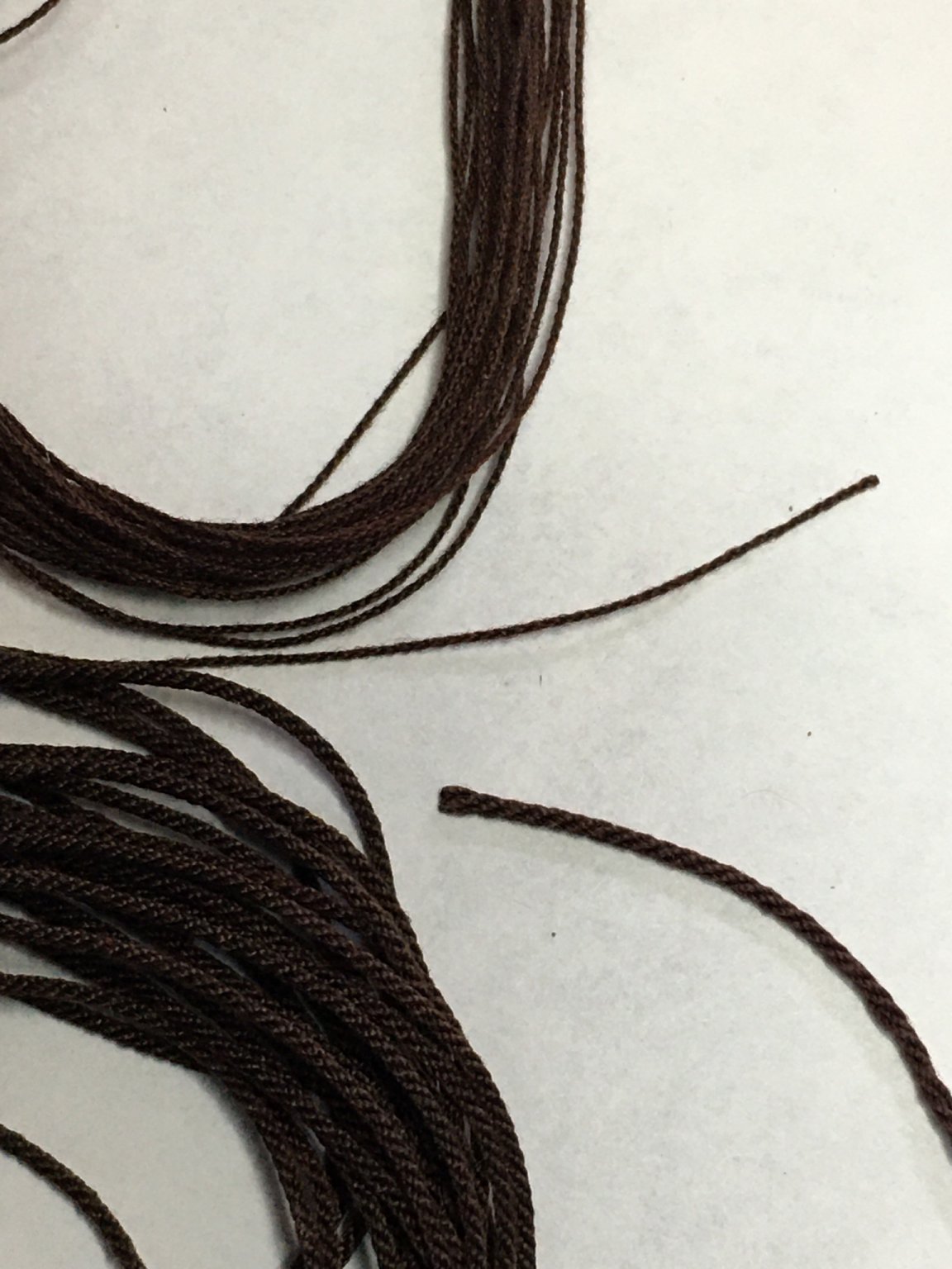
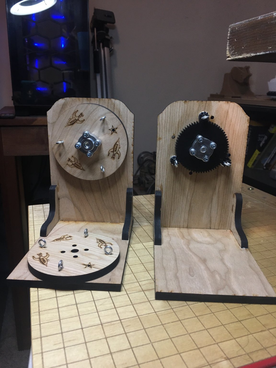
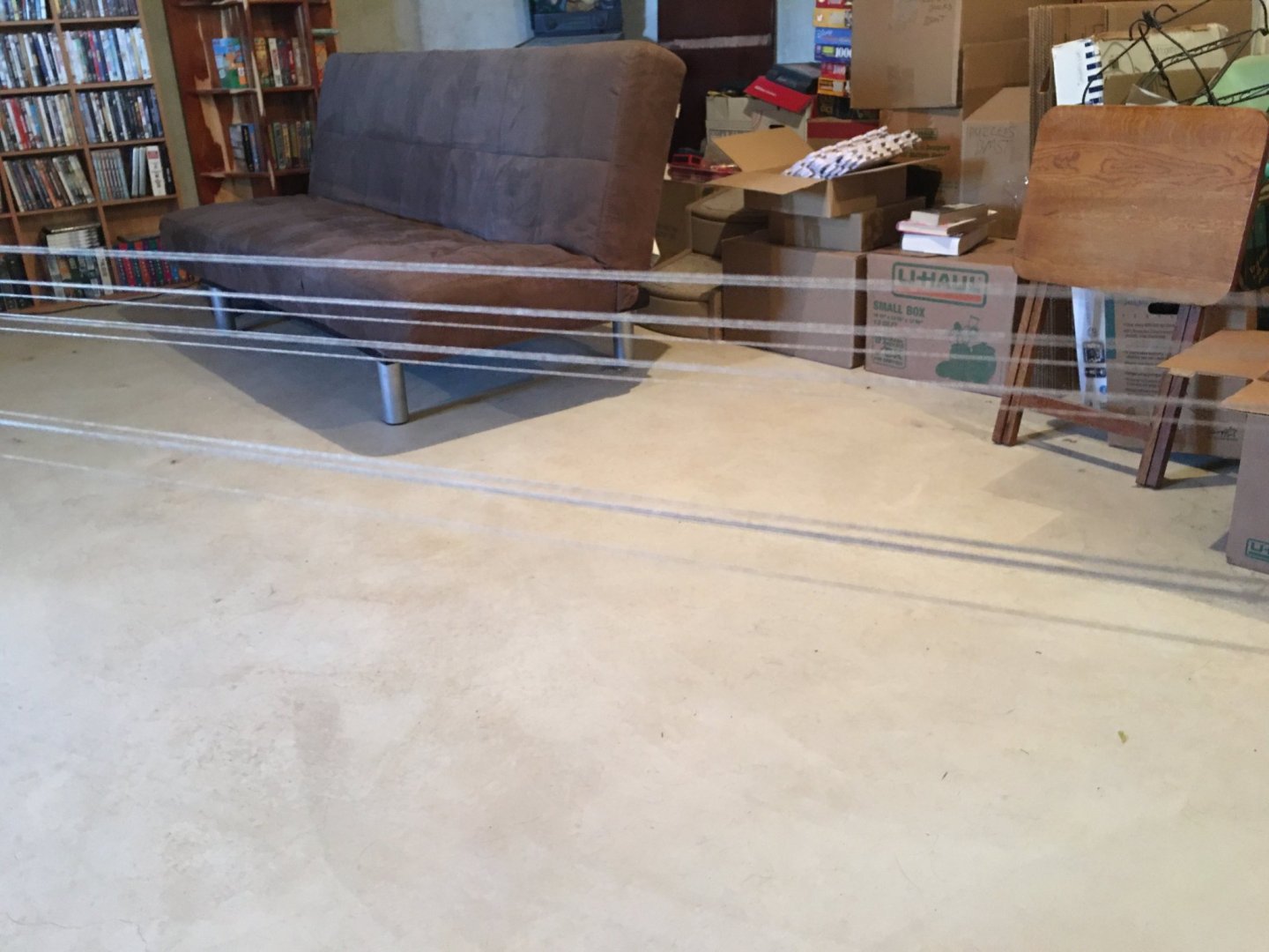
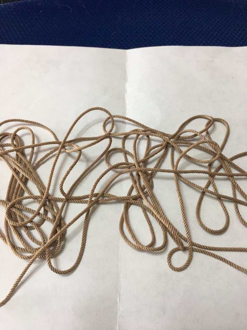
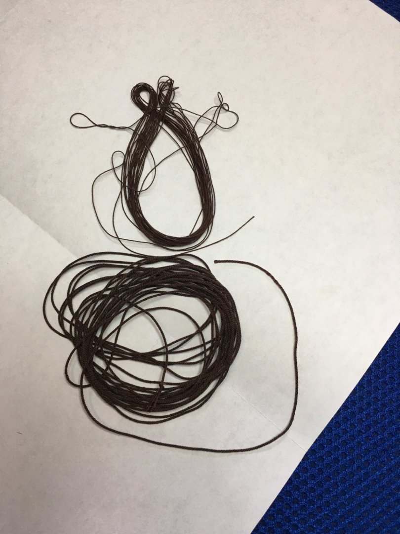
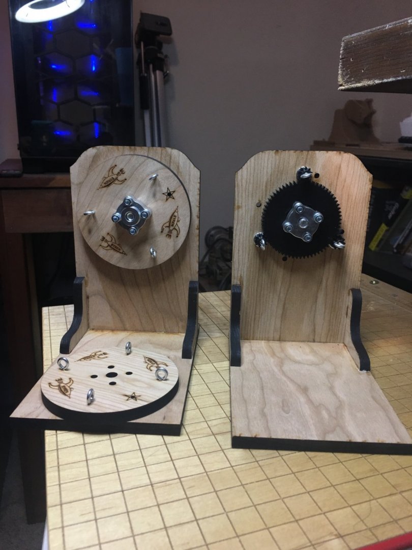
Success was had on another 20' length of rope, this one .080" or ~ 2mm diameter. Will likely be used for anchor cable on R.L. This required 4 threads of the Mara 30 size thread for each strand and 4 strands, for a total of 16 threads being stretched. Start to finish took me about 45 minutes, most of which was initial set up. I tie my threads one at a time. It is time consuming and I may look into finding or making a bracket of some sort that can hold multiple spools of thread so I can tie off multiple eyelets at once. For ease of access, I start at the lowest eyebolt then move to the rear most, foremost, and finally top so I am not trying to work over the threads. Once they are all tied on, you will have something that looks like this. it is a good idea to trim any overly-long threads so they do not tangle in the gears. Short tails, 1" or less are fine however. When tying, you want to try to keep even tension on the threads, but with poly thread, it is a bit more forgiving. Apologies for the fuzzy pictures, really need a second person helping to do this, but as you can see in the picture, my bottom 4 threads has one that is far away from the others especially compared to the gaps on the ones in the middle. The middle ones will be fine as they twist up, but the bottom I would tighten. Note: If a thread slips from your fingers before it is tied off, it is a good idea to pull the thread fully out of the stretched ropes back to the eyebolt and then re-stretch. Otherwise, you risk having the thread become tangled around the other threads from when it shot from your grasp. This happened to me a few times. Time to twist. In a counter clockwise rotation, twist the threads, allowing them to tighten merge into one strand so that there are 4 strands. Even if you are only doing a 1 thread per strand lay, you still need to do this step only rotate the drill clockwise for single threads and C.C. for multi-threads. Time to combine the strands. Rule of thumb here is whichever way, (clockwise or counter) that you twisted the threads, twist the strands. Start slowly, hand spin the first few rotations to see that everything is following as it should. You can see the center of the line merging together. The lay is not very tight yet, but all the strands are going in the correct direction. Time to add speed. Run the rope walk till the lines become tensioned properly. I recommend watching Chuck's YouTube videos as this is easier to show then write, and honestly it takes practice and experience to learn, of which I am still figuring out. I tend to over tighten. The line should look even and tight with only an inch or two free in front of the eyebolts on either end. I moisten the rope with water on my fingers while it is stretched out. Beeswax can also be used. This helps to set the threads and eliminate the "fuzzys" (technical term) that threads can develop. Hold tight to the rope before cutting so it does not shoot off across the room, tangling itself up. If laid up right you should get something like this once free. The only loose ends should be the 1-2 inches where the strands were tied to the eyebolts. The rest should remain a tightly laid up rope. If you end up with something of this nature when you release the tension on the rope and allow it to recoil, this means it is over-twisted, a comon and easy to correct issue. Under-tension results in the rope fraying and falling apart. Over-tension is easily fixed by running your fingres repeatedly down the length of the rope, allowing it to unwind til it lays limp and untangled. Rope after I worked the over-twists out. Next up, I lightly coiled the rope around my spread fingers to make a gentle coil that will lay nicely on the oven try I use to bake at 350 for about 4 minutes. Watch it closely as time varies with oven and you do not want it to melt. Remember this is poly-rope not cotton. Once out of oven, and cooled, (Do not grab rope immediately. It was in a hot oven, it will be hot.) it should lay like natural rope and is ready to be wound onto something or coiled and placed in bag for storage. I wrap mine around plastic bobbins and have them sorted by size and color on hooks. The pass/fail test is at the end, though if it did not unravel when cut from the eyebolts, chances are excellent that it is fine now, is if you take a sharp knife and cut, the end should be clean with no fraying. This one is good! Good luck to all, and I hope this helps!
.thumb.JPG.cd674b3d483bcfa2d6cdc08e31583e95.JPG)
.thumb.JPG.2cc5c8a6aaa0b627a19a2ad59a65c510.JPG)
.thumb.JPG.da2ceb6ba67beeeb2e3411437b53ae88.JPG)
.thumb.JPG.e27c8110f89f1f81be00d4f89fc1520b.JPG)
.thumb.JPG.ae8094030b04d39663f490c90abef338.JPG)
.thumb.JPG.d09dd50fb7523be66080b69b4b2b99a0.JPG)
.thumb.JPG.cc9bd34700ebc475689d528817c6fff4.JPG)
.thumb.JPG.2546c3e47a985fe1f6c697223385773b.JPG)
.thumb.JPG.5ca1b1f7c23d1fdad30d55dff1d5e420.JPG)
.thumb.JPG.ceb95ac688281a6bec675c7bddb29801.JPG)
.thumb.JPG.b0677a48a86e86fd86eff480b5df06cf.JPG)
-
I would imagine that all the ropewalks come with their own sets of pros and cons, I do not have experience with other ones so I cannot speak to those beyond what I have read. Set up is by far the worst part of the process. The distance does not make much difference that I have seen thus far. I'm sitting at about 21-22 feet between the two ends and that yields about a 19-20 foot length of rope. I am tempted to go further as I have a hallway I could run down to give me a little over 30 feet, but the 20 I am at now is comfortable. Also I read Chuck's warning that he had tried a 40+ run once and decided that was too much and had not done so again (or at least not written about it). It would be nice to make really long runs, my back yard I could easily get nearly 200 feet in a straight run, but Kansas winds, even on a calm day, would make this a nightmare, plus I doubt I could successfully keep the tensions even on the strands and would likely need the corded drills as I doubt the batteries would hold up for the amount of spinning that would be required. If my plans work out, I am going to try to make up some large diameter rope to see how multiple threads on a 4 strand lay up. I've done the smallest and a medium so I am curious on the large sizes. I will try to remember to take more step-by-step photos to share as this really is a good skill to have for any ship builder.
-
Thank you all very much! I am using Chuck's rope rocket from Syren and his recipe for a polyester rope made of Gutterman Mara thread. I have attached the pdf from his log to share. I bought the thread from Wawak.com. I did have to change the color for the lighter rope as I could not find the one he recommended of 2899, so I went with 696 which I can post a picture of later. The dark brown in the pics above is the same 868 in Chuck's recipe. It really is an easy skill to learn. Watch Chuck's youtube videos about it. It really is that simple. The hardest parts are determining the amount of twists applied and that is only learned through doing. I over-twisted both ropes initially, indicated by the ropes wanting to curl up on themselves. This was easy to undo by simply pinching the rope between my fingers and running them down the length of it allowing it to unwind until it laid naturally. Honestly, I struggle the most with tying the individual strands to the eyebolts as the lighting in my basement where I have the most room is horrible right now. The entire process takes me about 15 minutes to lay up the ropes and that is with a lot of start/stop time double checking things and just being slow as I learn. Then there is another 4-5 minutes of bake time to set the rope at the end after it has been cut free of the ropewalk. I have only made the two ropes so far though I will be making more likely this upcoming weekend as I need to get some in the running rigging color for the gun tackle. I am curious to see how the larger ropes lay up. These were only 3 and 4 strand ropes with 1 thread per strand. The larger ropes use multiple threads per strand and require a little more work on the initial twisting but I do not think it will be much harder of a process just more time consuming set up. I will be glad to keep sharing what I have learned, and highly encourage you all to try it. While rigging is far from simple, making the ropes themselves actually is. Chuck Passaro Rope Recipe.pdf
-
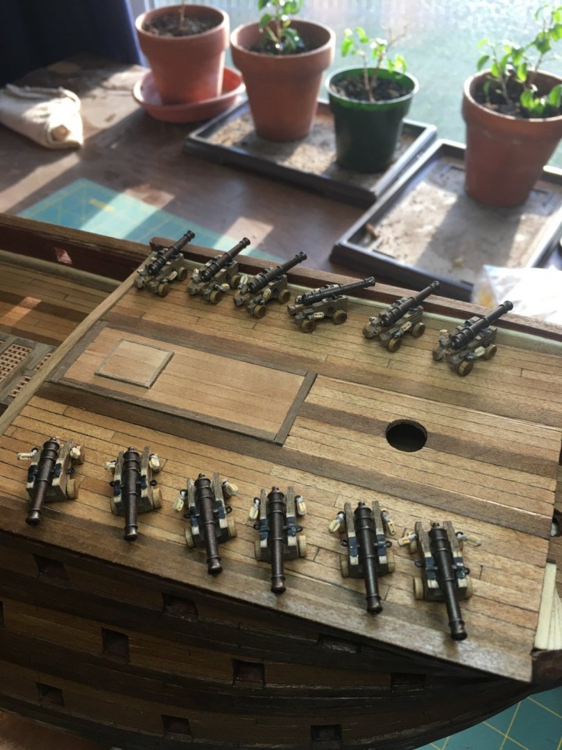
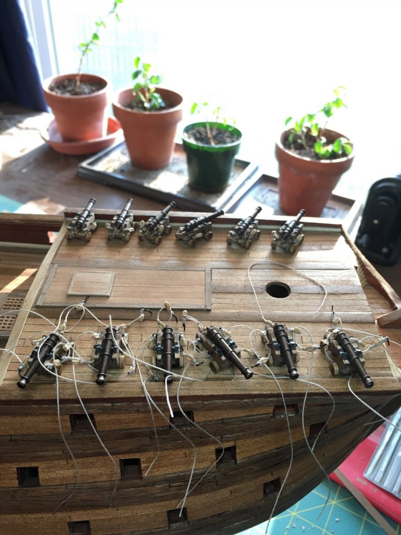
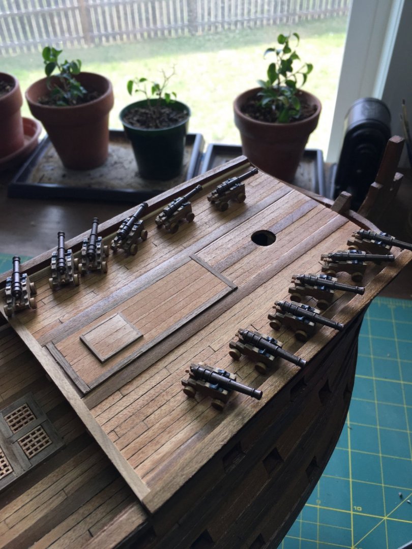
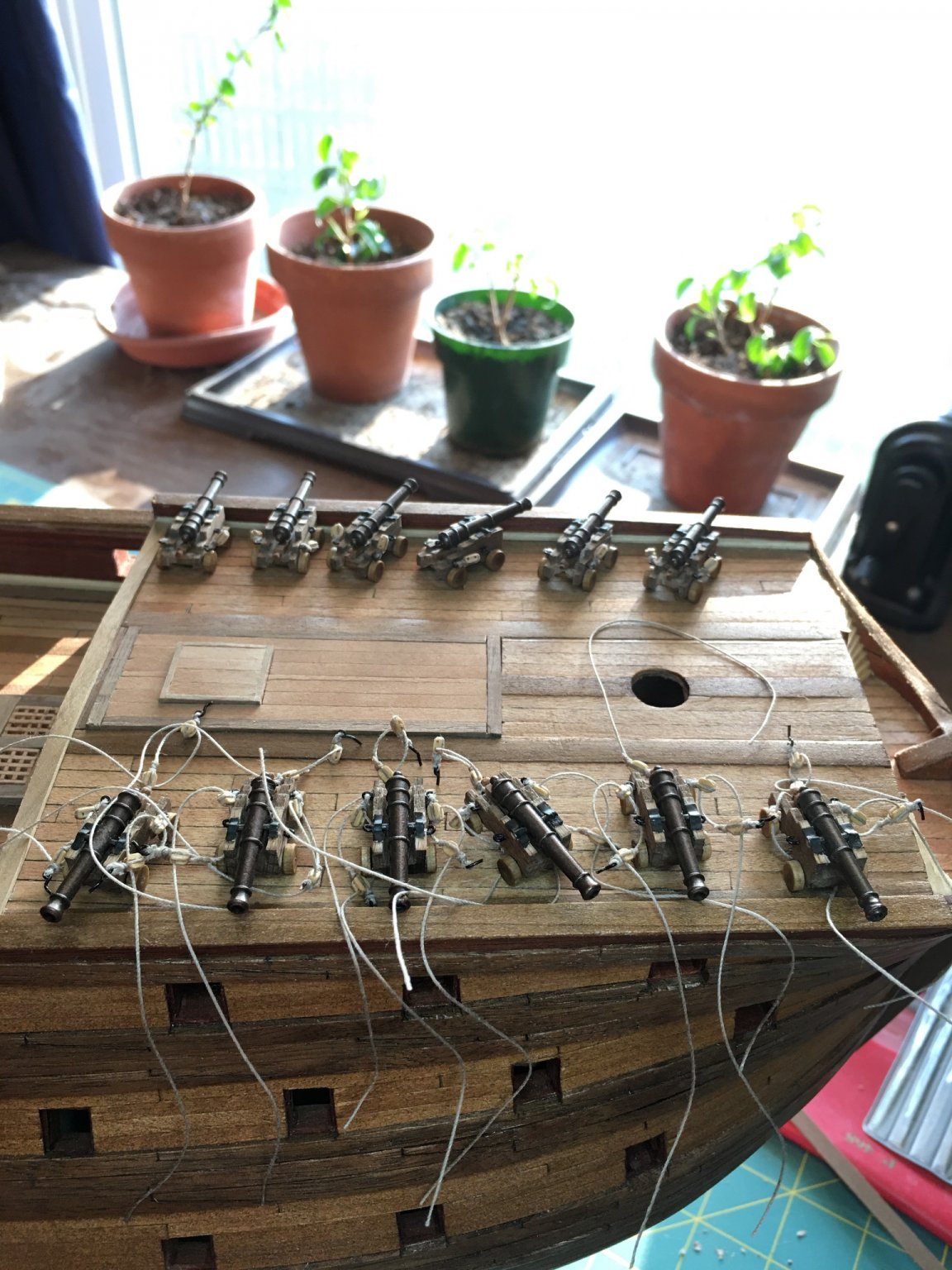
I have not had a lot of time for ship building lately but I have not closed down the shipyard. I have managed to assemble the canons for the upper gun deck that will need to be rigged in place before the ladders to the forecastle and quarter deck can be installed. I had to order more blocks for the gun tackle which should be here early this week. I did find time to finally try my hand at making my own rope. Made up 20 foot lengths of .018 and .035 inch ropes today and am fairly happy with how they turned out. Took some time getting used to the setup on the first go but by the second, I was moving much faster and the whole process is surprisingly easy and not that time consuming.

-
Great idea using the belaying pins as temporary clamps to hols the lines in place. I had not thought to do that but will likely give it a try. That is always one of my fears is securing a line too soon and needing to free it from glue to readjust.
- 786 replies
-
- 3
-
-
- Royal Louis
- Finished
- (and 1 more)
-
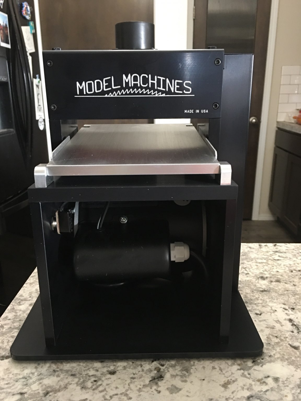
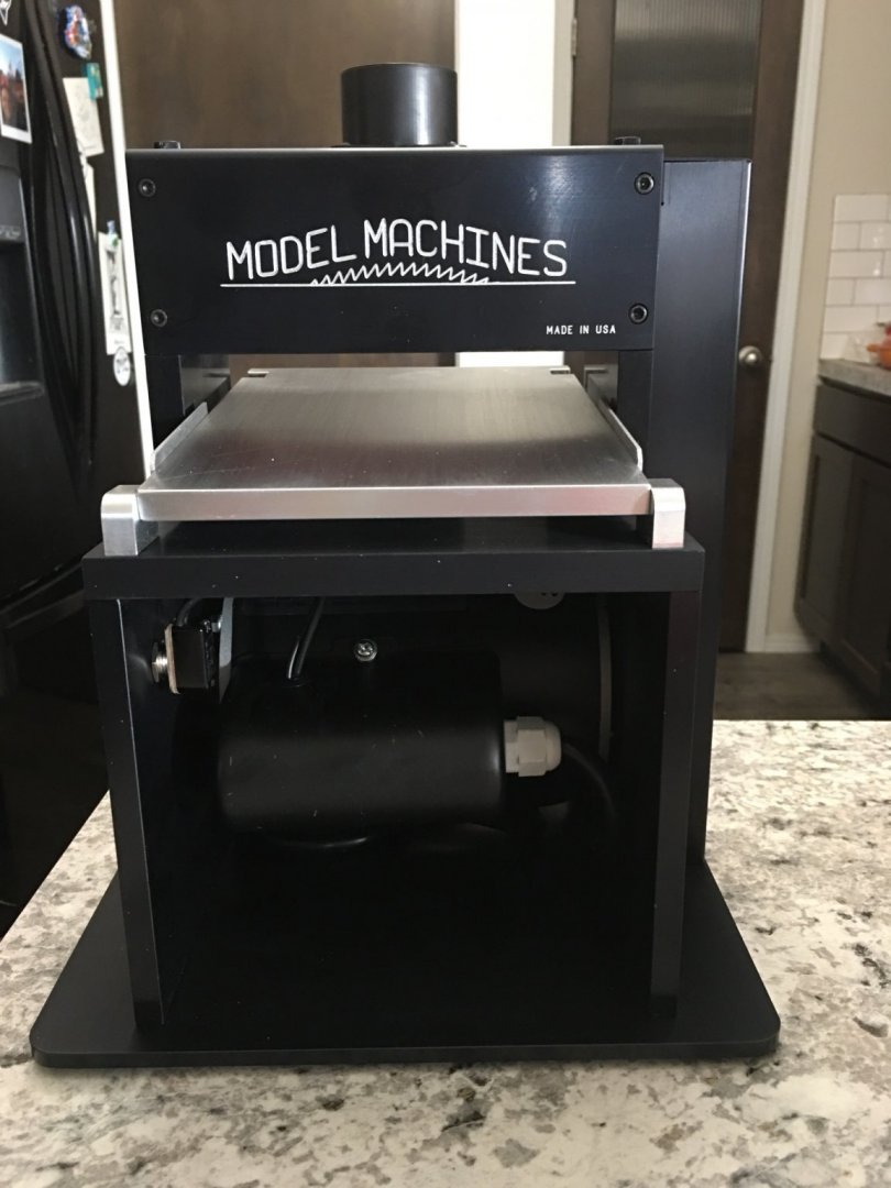
Bought myself a birthday present in the form of a Byrnes thickness sander to add to the shipyard. Been wanting to get one for a while and finally pulled the trigger. No more uneven planks!
-
Le Soleil Royal by Nek0 - 1/72 - Marc Yeu
EJ_L replied to Nek0's topic in - Build logs for subjects built 1501 - 1750
Congratulations Marc!! May you, your wife and little Julia have a blessed and happy life!- 208 replies
-
- 4
-
-
- le soleil royal
- 104 guns
- (and 2 more)
-
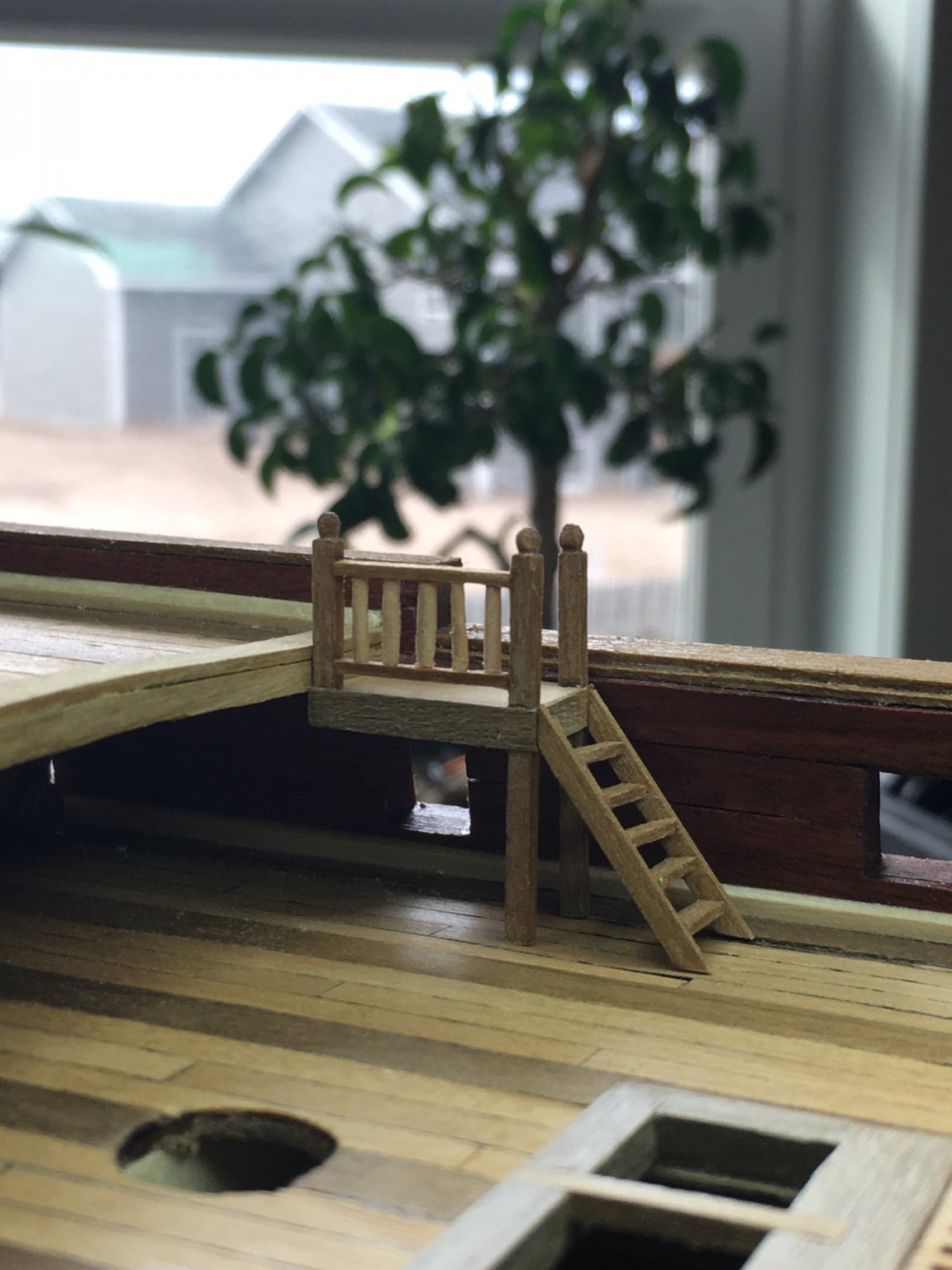
More work on the quarter deck ladders and handrails. The open spaces between the posts will be filled in with carved styrene.

-
Great recovery on the oversized gammoning holes. Those plates appear to be natural parts that should exist there. She is looking fantastic and congratulations on finishing the standing rigging!
- 786 replies
-
- 2
-
-
- Royal Louis
- Finished
- (and 1 more)
-
Beautiful work as always. On the issue earlier on the ratlines or other access to the mast heads, I was reading in the book, Historic Ship Models, by Wolfram zu Mondfeld that prior to the 17th century, and later depending upon the type of ship, ratlines were not common use. Instead, a narrow rope ladder was hung from the mast head and let fall along the mast for sailors to climb. It could be easily swung clear of masts and sails for both square and lateen rigged sails. If you are looking for an interesting detail to add, this might be one that would be simple enough.
- 222 replies
-
- 1
-
-
- reale de france
- heller
- (and 1 more)
-
Thank you OC for the nice words and to all for the likes. Wow! Pictures can be cruel and/or helpful depending upon how you view things. In this case, I've noticed just how crooked my steps are! Fortunately as nothing is secured on the ship yet it will be easy enough to correct. Going to have to see what shifted though and try to catch it faster on the next set. With those steps, my sailors would be thrown overboard with ease! Haha!
-
Bravo Marc! I think one of the things I love the most about watching your log is not just the ship building but the lessons in critical thinking a strategic planning. You provide such an in-depth look at the how and why of each component, looking at them from both the form and function as well as the artistry. Through your rationalizations, I have found myself better understanding both model ship construction but also details of ship design and function that I really had not thought of as they are often completely ignored on most models. Example, the drains for the seats of ease in the Q.G.s. There is a wealth of knowledge already here and to think, there is still a long way to go till completion!
- 2,699 replies
-
- 3
-
-
- heller
- soleil royal
- (and 9 more)
-
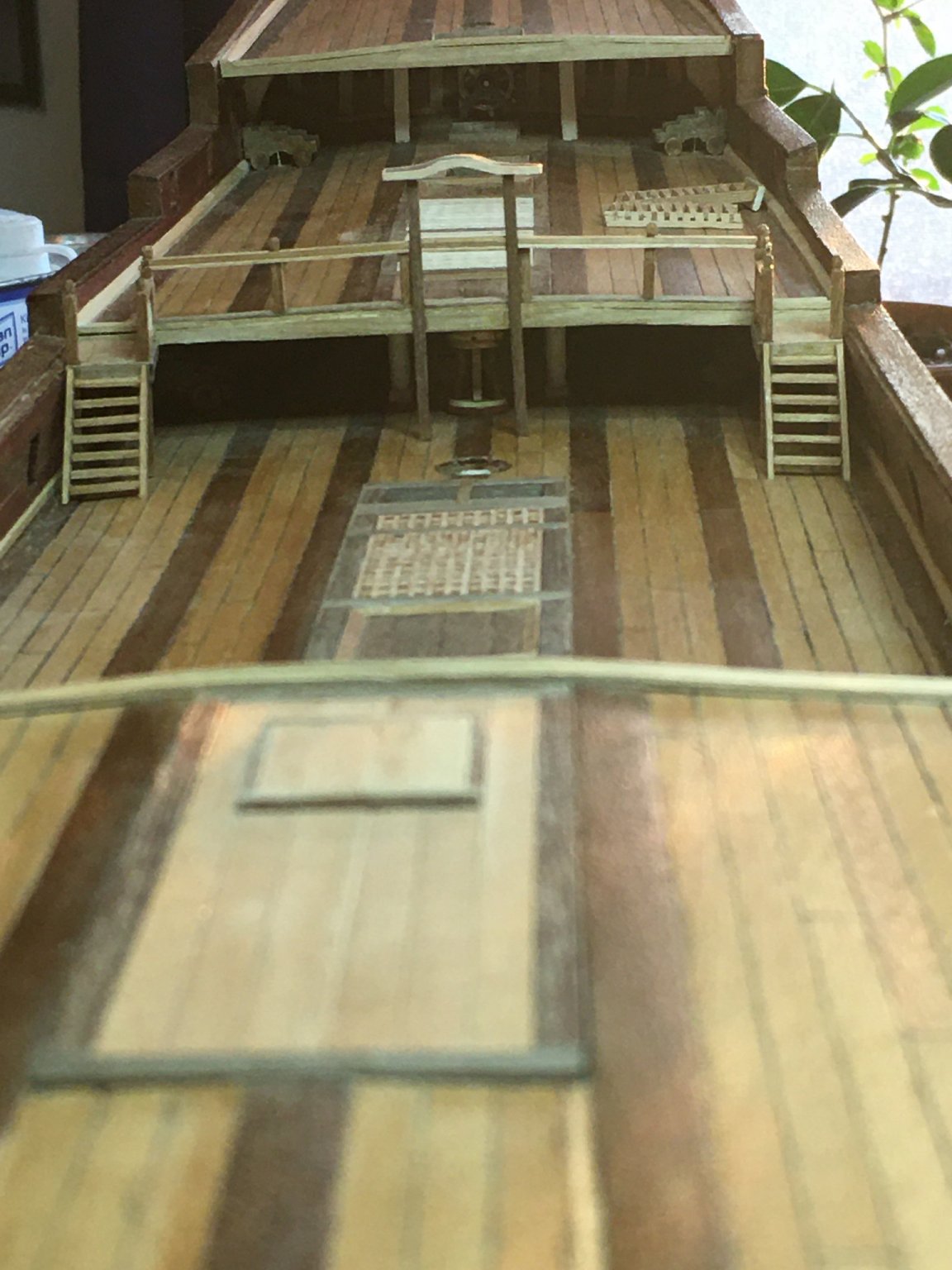
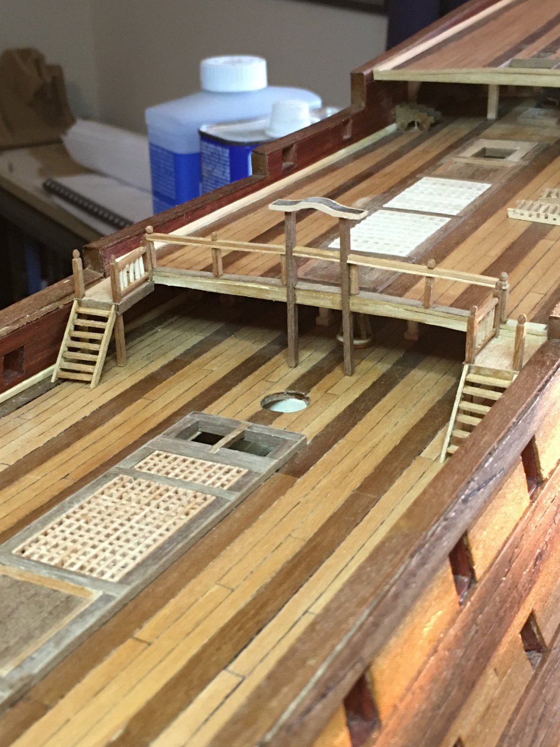
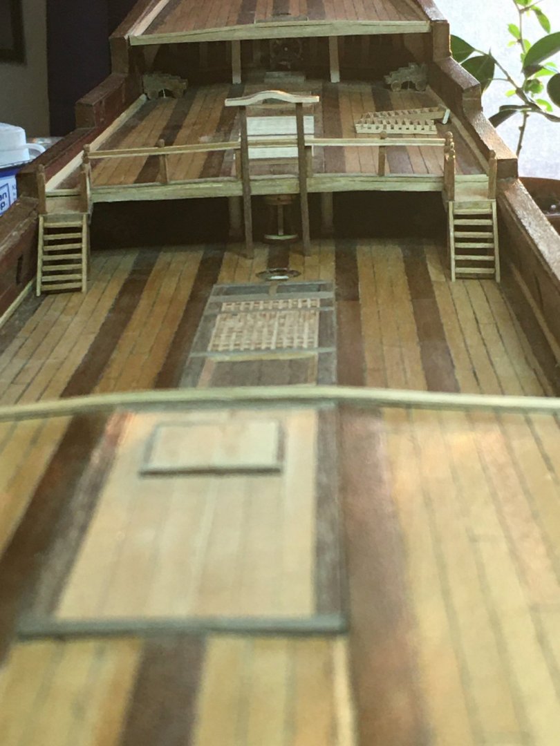
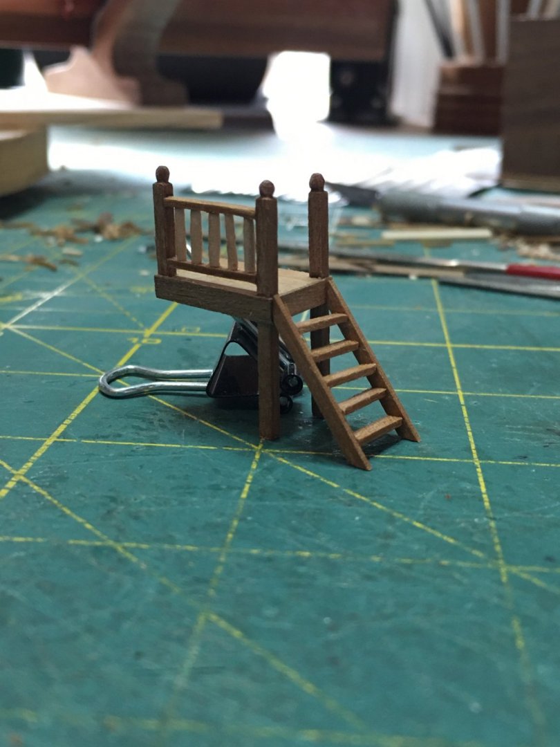
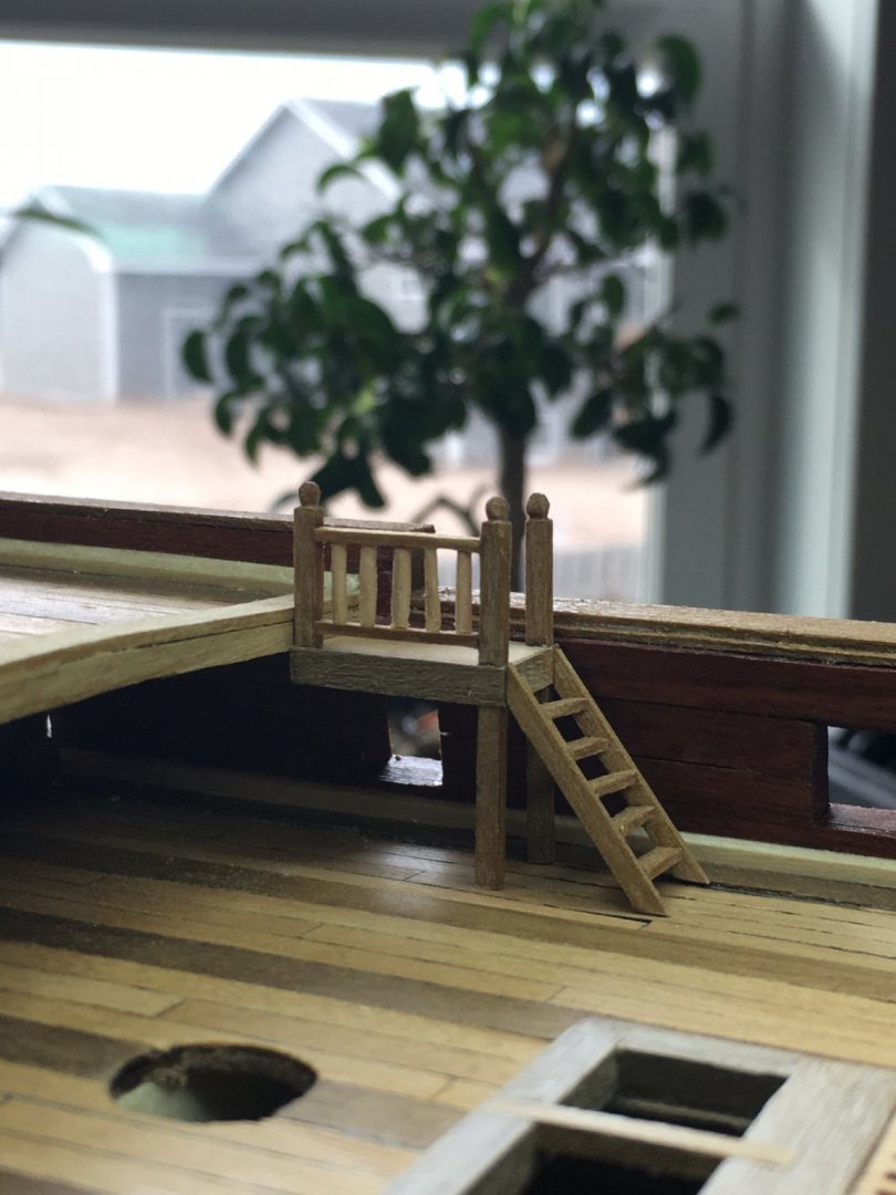
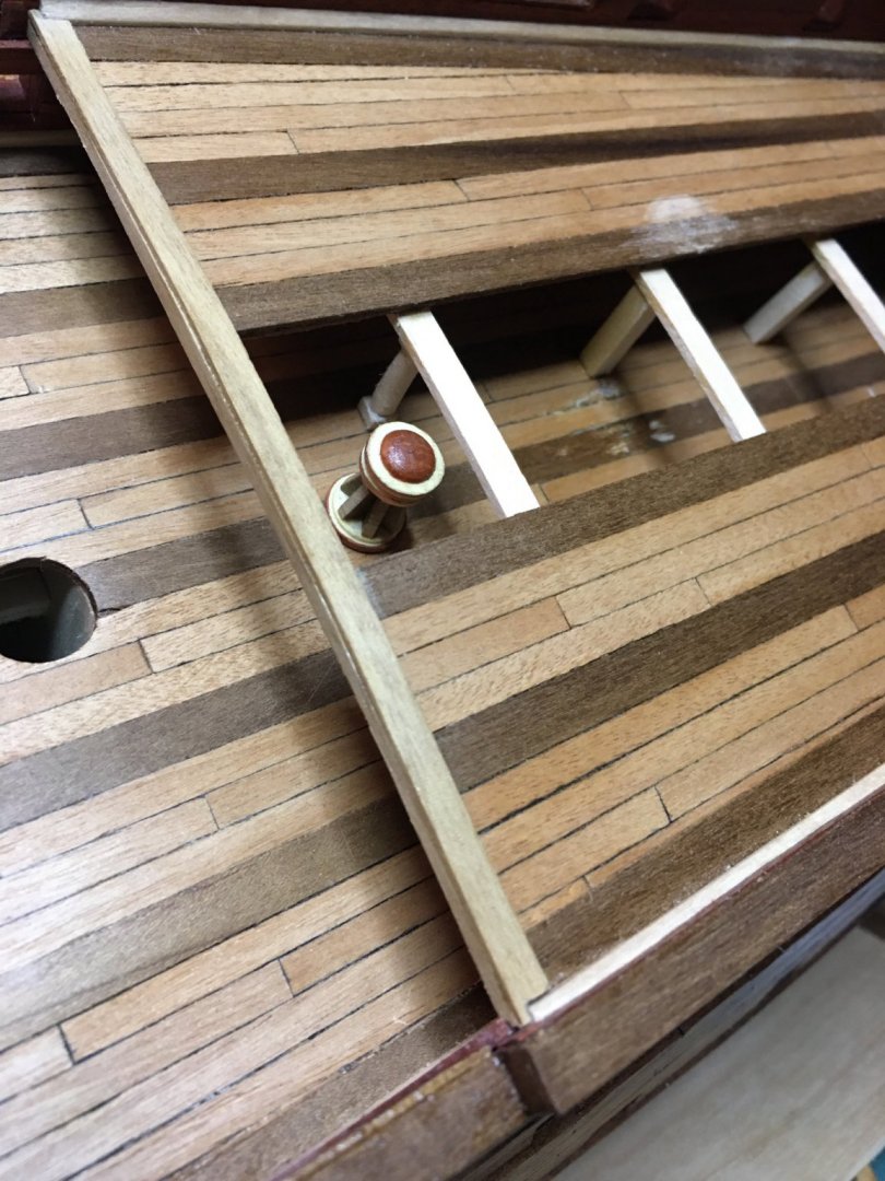
Work on RL has been slow lately, a lot going on that is occupying my time, still some progress to show. While I am figuring out how to make better gratings as I am not happy with the current ones, I started building some of the misc. structures. First up are the ladders to the quarterdeck. These came n cast metal pieces, which don’t look bad really, but I prefer to replace them with wood. I have one set nearly done and another just lacking the ladder to the platform. These will not be glued I. Place until after I fit the canons beneath.
-
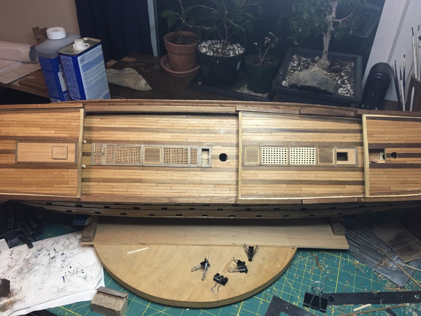
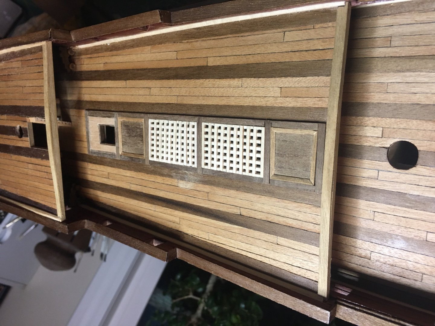
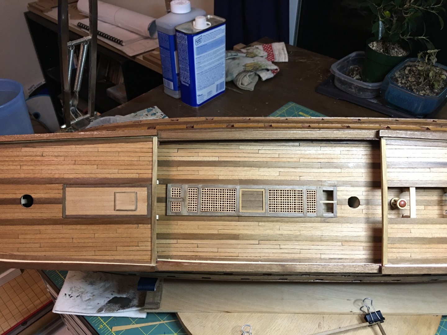
Some more work on the hatches, coamings and grates. I have not glued or applied finish to any of them yet as I’m still adjusting but things are coming together. I did not get a chance to do much with gratings, the weather finally cleared up and heading out to ride my trike as well as doing some repotting of my bonsai trees took precedence. The ones in place now will all be replaced at some point in the near future though as I’m not happy with either set. I am also starting to look at how I will create the ladders. For spacing purpose, I built one of the kit supplied ones, but they have the same badly pre-cut parts as the gratings and do not make good looking ladders. So those will be custom built as well. Need to make a new template though. I seem to have lost my old one... My other distraction arrived last week as well; the Syren Rope Rocket. I got it assembled and have begun learning to use it. Will post results once I have something to show. I have never made rope before, for any reason, and am looking forward to learning a new skill.
-
Welcome back! Errors and mistakes happen even on the best models. You said the only words that matter on a personal hobby, you are proud of your creation. It is a great model. I have used it for reference for my own RL build many times and I am certain others have as well. Push through and finish then display her proudly!
- 786 replies
-
- 2
-
-
- Royal Louis
- Finished
- (and 1 more)
-
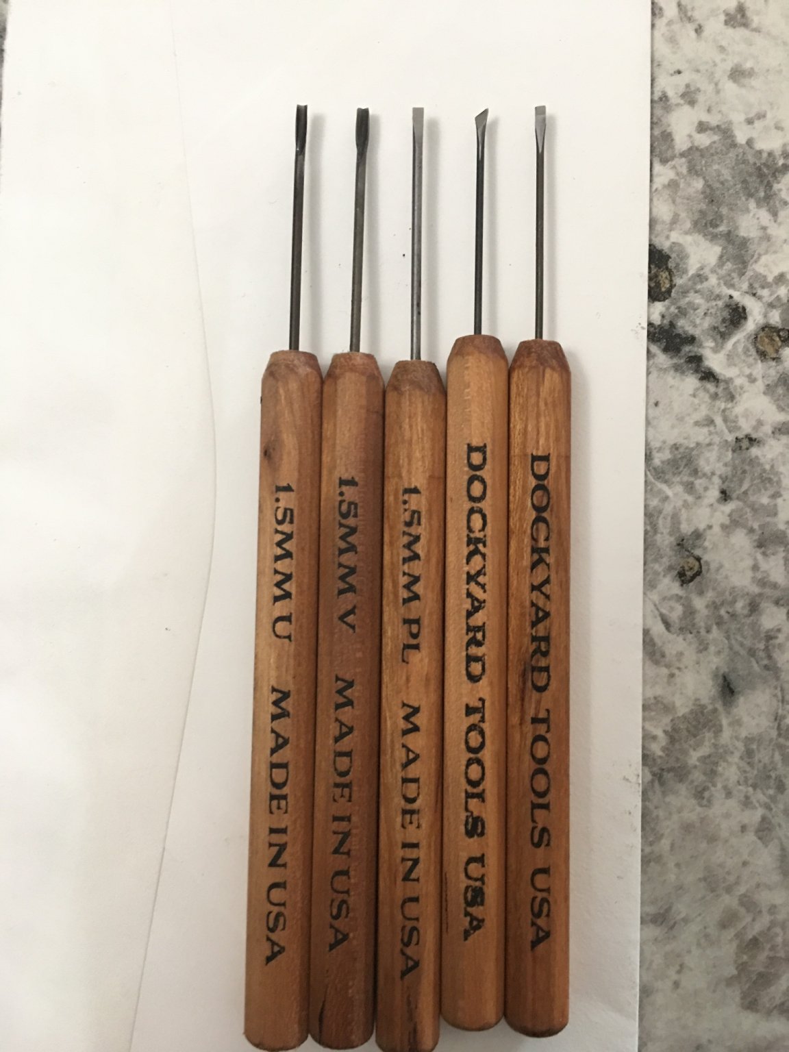
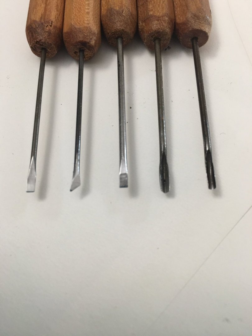
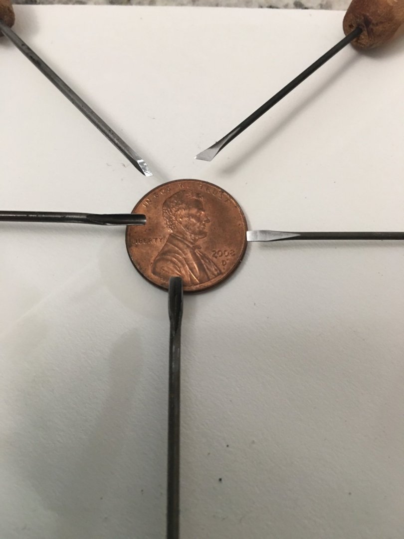
Still debating the capstan issue and other things... Going shopping for some lumber to practice making gratings on this weekend. See where that gets me. On another note, I did receive my new micro carvers today! Now once I’m ready to resume carving decorations, I have a few new quality tools to help me out.

-
Hmm... An interesting conundrum. It does appear that the deck is more solid without a removable access on the Musee de la Marine which would make more sense to me. However, the pictures of the Quinze model which shows gratings immediately behind the capstan change my theory that they would not place a capstan on that section. I would have thought that a capstan would generate too much torque and stress on the framing that they would not be we suited to sit over the thinner hatch cover pieces compared to the more solid main deck framing and planks. Perhaps the framing and planking at the capstan was thickened and reinforced, (something that is hard to tell on a model). The Quinze pictures could be suggestive of this as the deck appears to be more solid and of a darker color, something that was often noted as representing thicker planking in models as it is nearly impossible to tell otherwise. It could also be simply aged wood and coloring combined with distortions in the photo and my own reading too much into it... On the stove pipe issue on the Quinze model, it is my understanding that the galley stoves were more typically located on the middle gun deck, not the upper. This has been another confusing point on my own model as the plans call for a small room (presumably the galley) to be built under the forecastle. I built this room as it could be either the galley or another small storage space. In either case, it would be easy for the stove pipes to pass though it and still leave most of the space functional for other uses. On the Quinze model, the galley stove could reasonably be placed on the middle deck and the pipes run up through a grating on the upper deck to the forecastle deck had they been modeled. Stove pipes are not uncommon to not see on historical models. I would think that they may often times have been overlooked as a non important detail to the modeler, or broke off and lost over time.
-
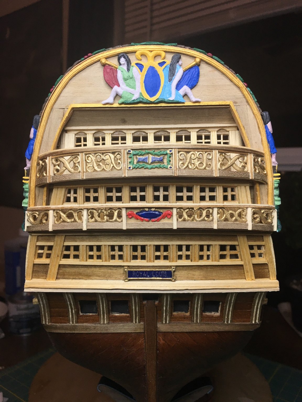
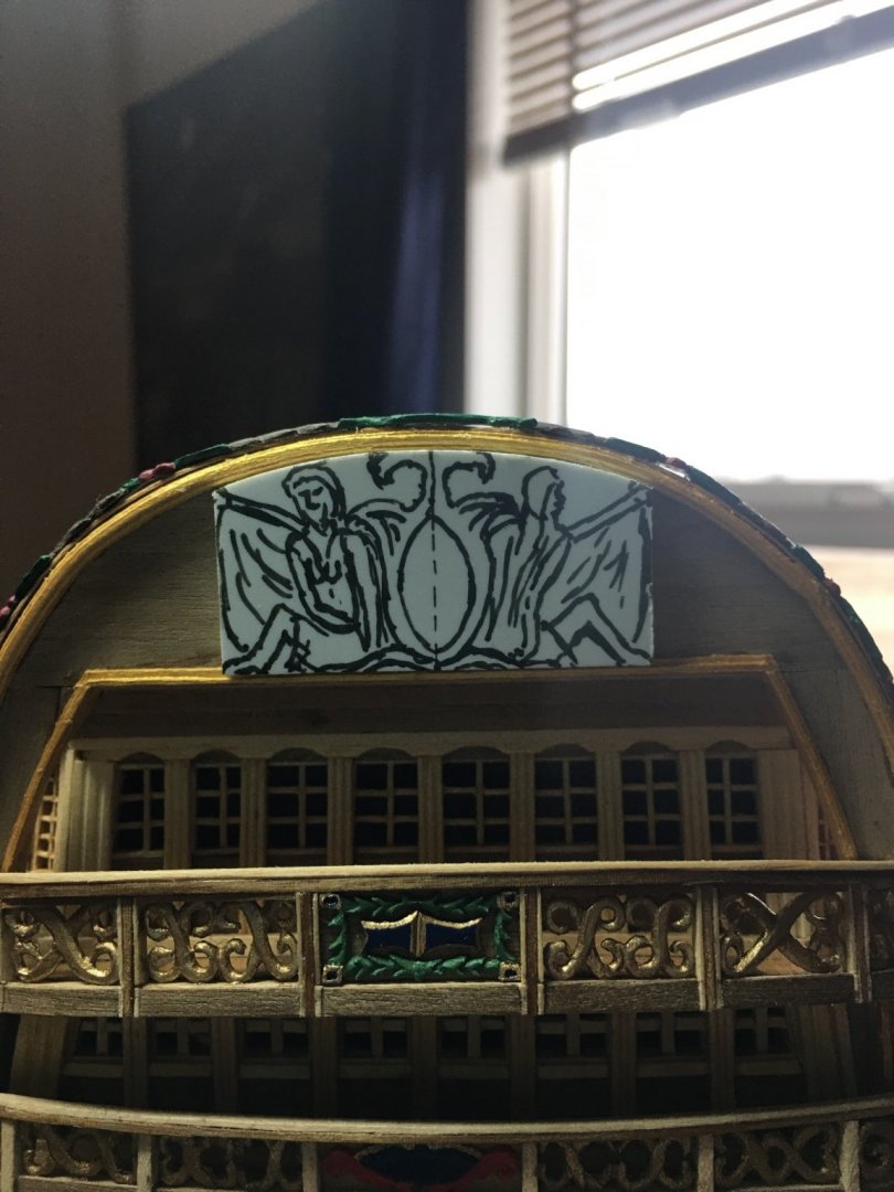
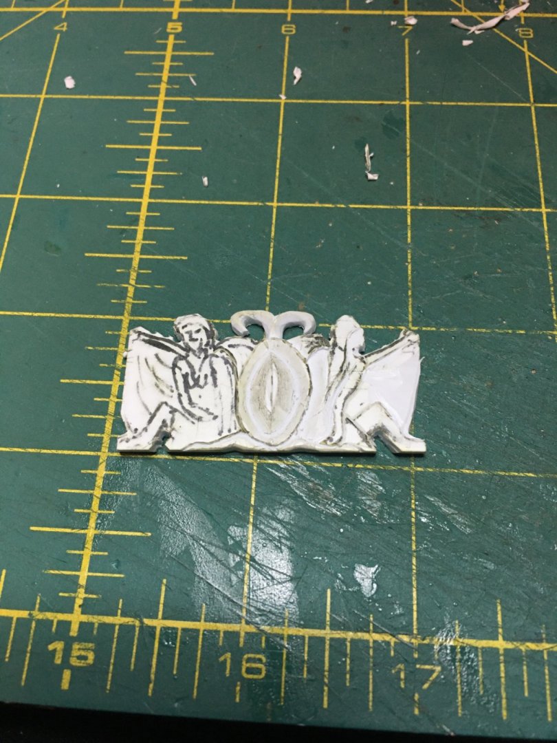
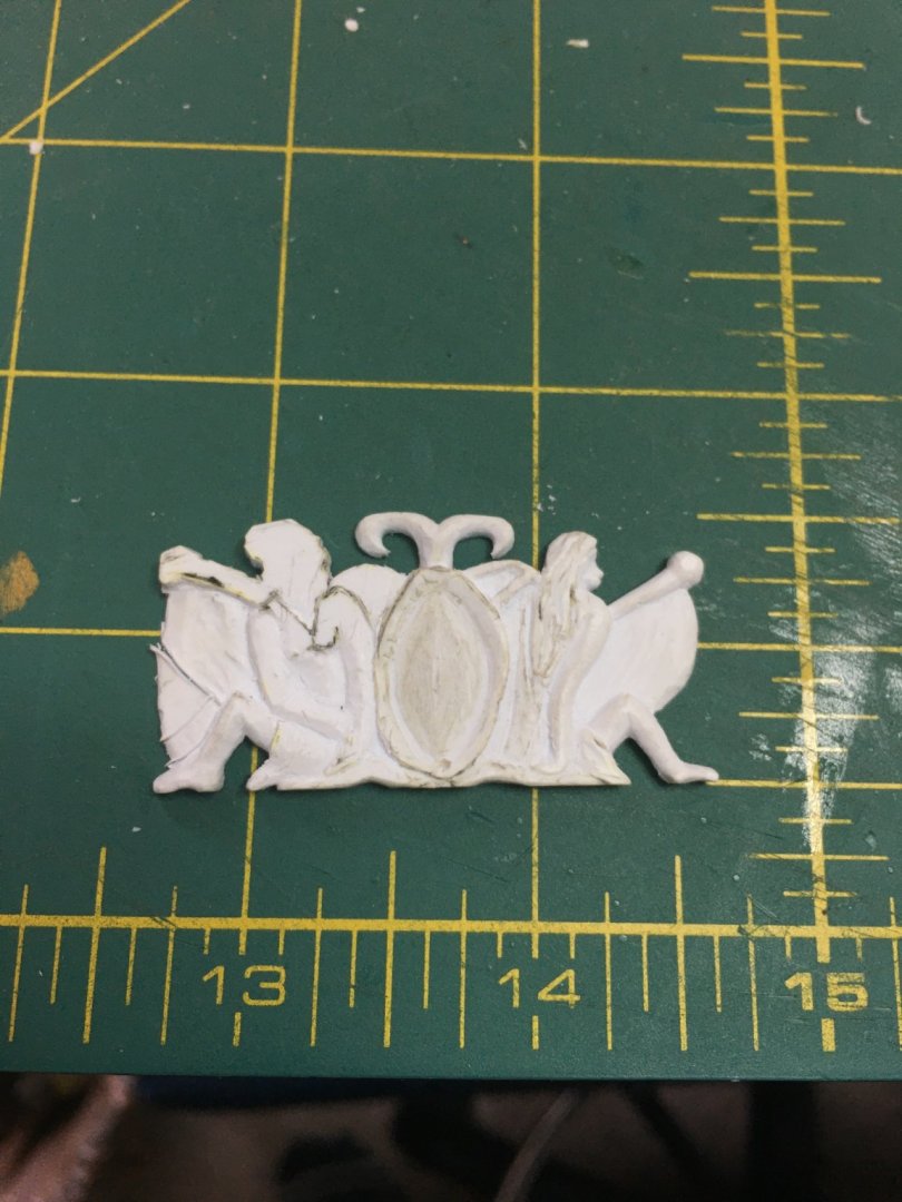
A couple more carvings added to the frieze brings it to near completion. Paint touch ups and some glue and it will be done. Not the best picture I know. I will try to take some better ones soon. I have stopped working on carvings for the moment. I finally broke down week before last and ordered some nice micro carving tools from dockyard tools but due to that wonderful winter storm that buried and froze a bunch of us out here in the middle, they have been delayed. I’m hoping they arrive later this week. While I wait on the tools, I decided to work on the gratings and coamings. I built the set for the main deck and while I am okay with the coamings, the kit supplied gratings are not very good. I am thinking I’m going to try to make my own gratings to replace these. Never done that before so yet another chance to learn a new trick... On the forecastle, I had some design questions that I could not get definitive answers and so I took best educated guess. The kit plans show the forecastle having a removable section of deck much like the hold gratings amidship. It also shows the galley funnels emerging through the smaller square and it has a capstan on the larger section between the funnels and the foremast. I accepted the galley funnel access easily as that access would make repairs and service much easier. I can also get behind the larger access hatch for a few reasons. While uncommon to have a hatch on the forecastle, it was not unheard of and on larger ships, I would think it a good thing. Loading/unloading of the bow would be easier to undertake and venting fresh air down below decks would also be enhanced. R.L., at least this version is a late 18th century ship. During these years, the ship design was much more understood with more practical and less experimental designs being used. With that line of thought, I decided to keep the access hatches on the forecastle, though I did reduce them in elevation to sit just slightly raised above the deck to help with water control. The item I found myself against was installing a capstan on the forecastle hatch cover. I combed through every book I have on ship models to try to find an example of any vessel that had to be mounted in that position. I found none. Now, where the confusion likely lies is that a ship of this size would have had two capstan. One would be a large, likely double capstan abaft the main mast and the other a single abaft the foremast, below the forecastle on the upper deck. Also another reason for the removable hatch cover above it on the forecastle. Ropes could then be led through the hatch to blocks and pulleys on the deck and then to the capstan. Hidden capstans are no fun on models so we have the deliberate and understandable reason by the model manufacturer for moving it up a deck. The other reason is that while I could not find a forecastle mounted capstan, the do exist in that area, just not on the forecastle deck. Main decks nearly always had a capstan or wench typically placed abaft the foremast though sometimes a winch would be forward the foremast. Used primarily for anchor duty, it would be easy to mistake the placement of this item as many people associate the catheads with the raising of the anchor ropes when that is primarily done below decks where the rope enters through the hawse holes. On later vessels, the anchor chains would often come aboard on the upper deck before descending back below decks to storage. I may be wrong about all of this, (Would not be the first time) yet I think my reasoning is at least sound for my decisions on the model. In any case, I relocated the kit provided capstan to set abaft the main mast on the upper gun deck. I used the kit piece with minimal detailing as it will not be easily visible once the remaining gratings are in place over it. More for my satisfaction in knowing it is there. Similar to the ship’s wheel on the quarter deck. On a final note, yes, I did leave the coamings squared off and raised above the deck. I know that French ships traditionally had curved coamings and gratings that abutted nearly level to the deck but I have also read that by the late 18th century, most vessels had switched to squared coamings raised above deck. I cannot say for certain what R.L. had. Nothing is glued yet on this model. My intent as of time of this writing, is to see what it will take to make a cambered grating. The coamings are easy enough. If I can manage to create decent gratings, then I may change to a cambered hatch. If not, then I will stick with the square. I do not feel that either is fully right or wrong, just aesthetics really. If this was a 17th century model, then a cambered grating for a French vessel would be correct. Enough ramblings for one evening. As always, thank you all for stopping by!

-
Wow! Excellent job on that tide line and the moss/algae even high up. The crusted buildup reminds me of the docks in the fishing communities back home in Louisiana. I think that will look great with the water lapping alongside. More and more amazing with each update!
-
I feel your pain! Working with construction drawings daily, translating between flat paper and real life construction has become second nature. That being said, buildings are typically and simply, a series of cubes, right angles, parallel and perpendicular lines. As long as you can envision x,y & z dimensions, it is relatively simple to take a flat drawing and make it 3D. To my constant frustration, ship building is not as simple. Yes, the x,y&z dimensions still apply, but rarely is anything square, parallel or perpendicular to another item. Even when they are, the many curvatures of hull, and decks, varying angles of mast rakes, and often the reference picture we are using itself, is an artistic rendering of the ship at sea making the entire vessel angle in bizarre directions. Subtleties abound that frequently cannot be well portrait on flat surfaces therefore making us unaware of them until we try to fit that straight edge against a piece that is curving in three different directions. All of this places me in awe of the ship builders of the era. These men were nothing short of geniuses in their fields. Today, we cannot construct a rectangular box without dozens, sometimes hundreds of architectural and carefully engineered drawings, schematics and specs, where these people built towering ships often larger than some of the aforementioned buildings, that not only floated, they sailed in rough seas and withstood bombardment from enemy canon fire. All of that was without modern CAD programs and engineering. The plans used then, if any, were barely more that what we would call a cocktail napkin sketch. It begs the larger question of how much have we truly evolved...
- 2,699 replies
-
- 9
-
-
- heller
- soleil royal
- (and 9 more)
-
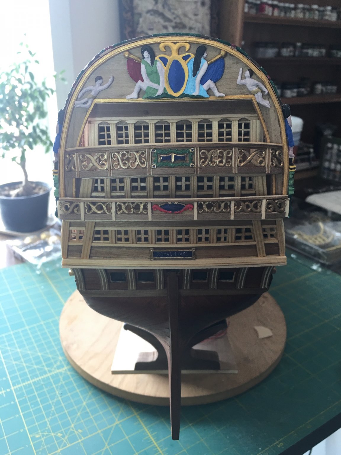
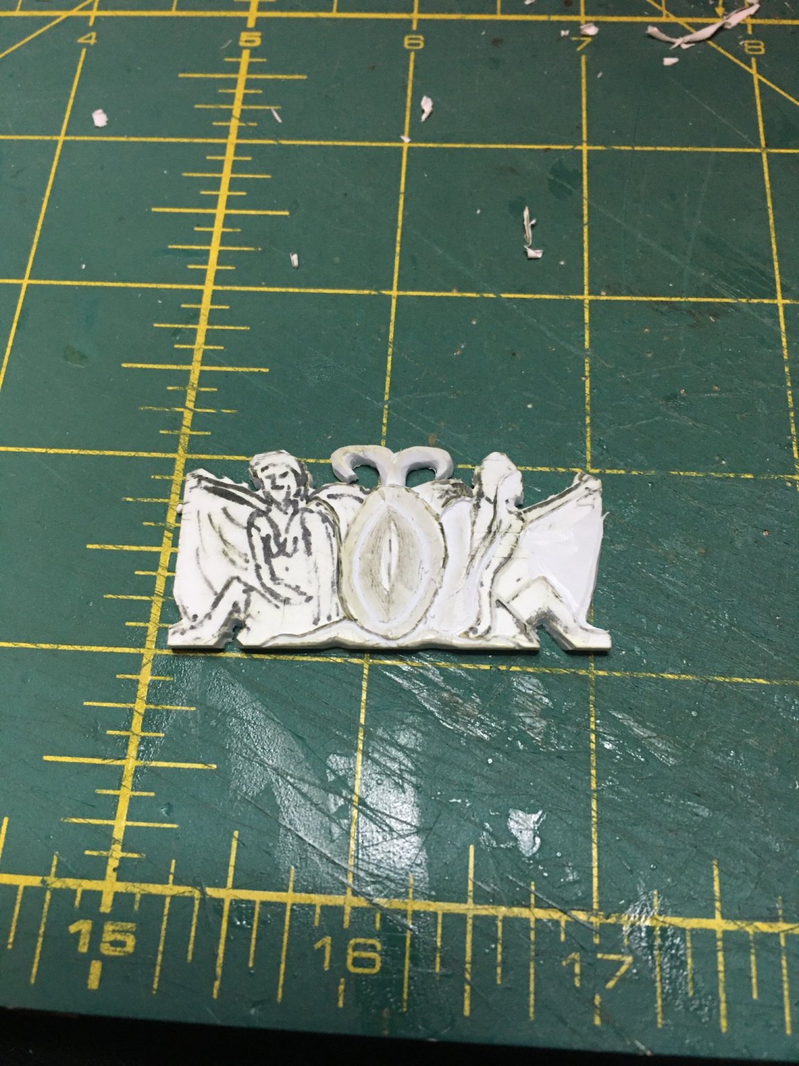
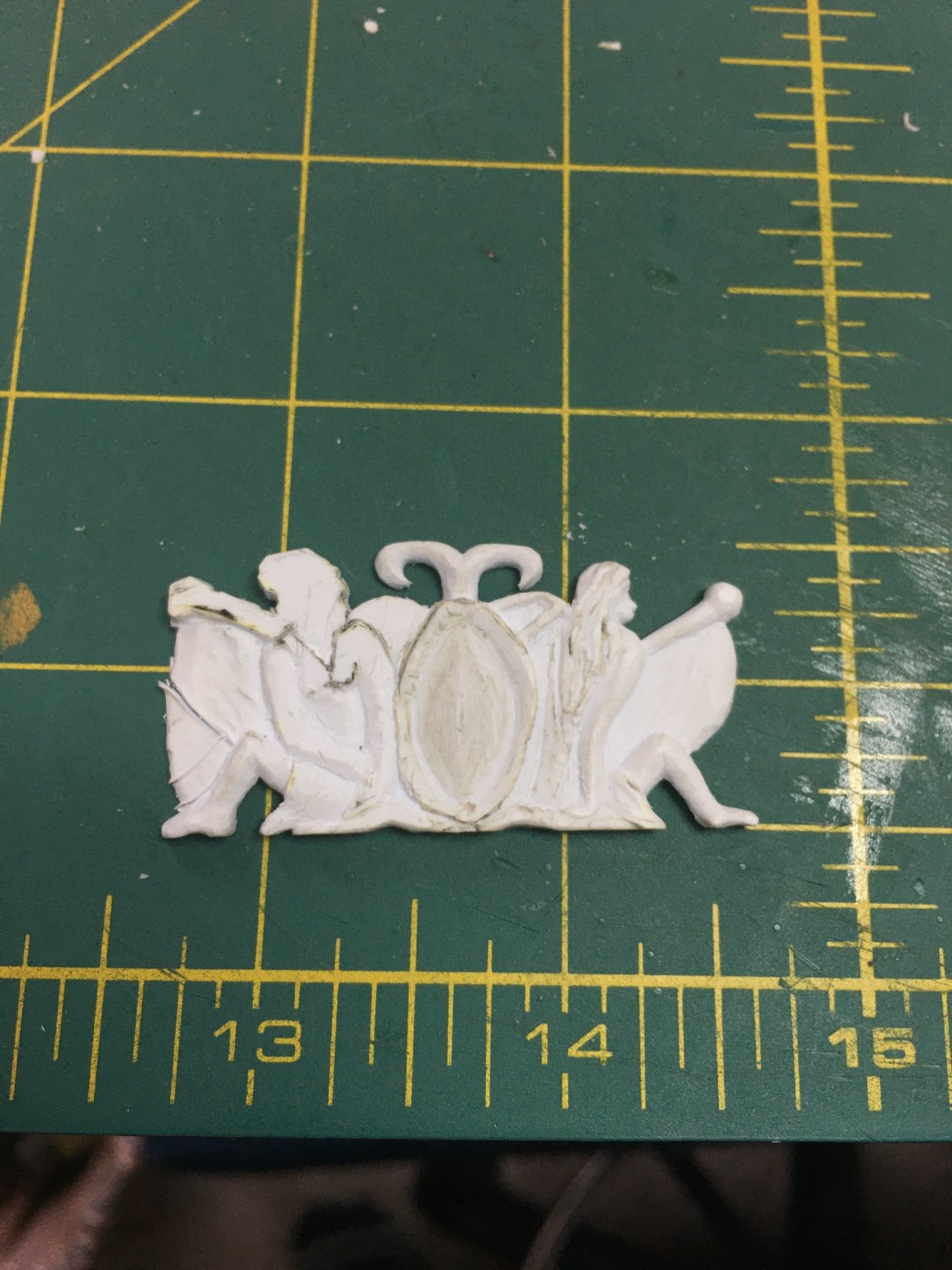
Frieze sculptures are progressing. The center piece is nearing completion and I will begin working on the cherubs next.


.JPG.993c65fc51af5b0affce04b7b1ddcaea.JPG)
.JPG.139d9814be9da708d5ca9c3df47846cc.JPG)

.JPG.da2c424555371322fe8ccc27e26e870a.JPG)
.JPG.3ab285813844afe7eb499020f4a6a7db.JPG)

.JPG.b0379544ab467cb9e4c352f0c770e484.JPG)
.JPG.cf24f71339534a354f0bff227f354b25.JPG)
.JPG.f33d578b0d9a0c90ad9687cda231222b.JPG)
.JPG.5af5aaa1d196154a469ceae6f91bd3d2.JPG)
.JPG.35b690af076004dd347ca9184c7aef96.JPG)
.JPG.be1d3173acd5c4d6e288d0fa2aa34466.JPG)
.JPG.cafe32ec4c6180dee885d1f7a8289bfb.JPG)