EJ_L
-
Posts
2,246 -
Joined
-
Last visited
Content Type
Profiles
Forums
Gallery
Events
Everything posted by EJ_L
-
 Adding more frames. Nearing the mainmast soon. To get a better idea of the hull’s full size, I added the futtocks and top timbers at the widest section. Yes, one side is leaning inward and needs to be adjusted… A buddy of mine was having trouble picturing how big the model was getting so I took a picture of me in front of it to give more perspective.

- 47 replies
-
- 15
-

-

-
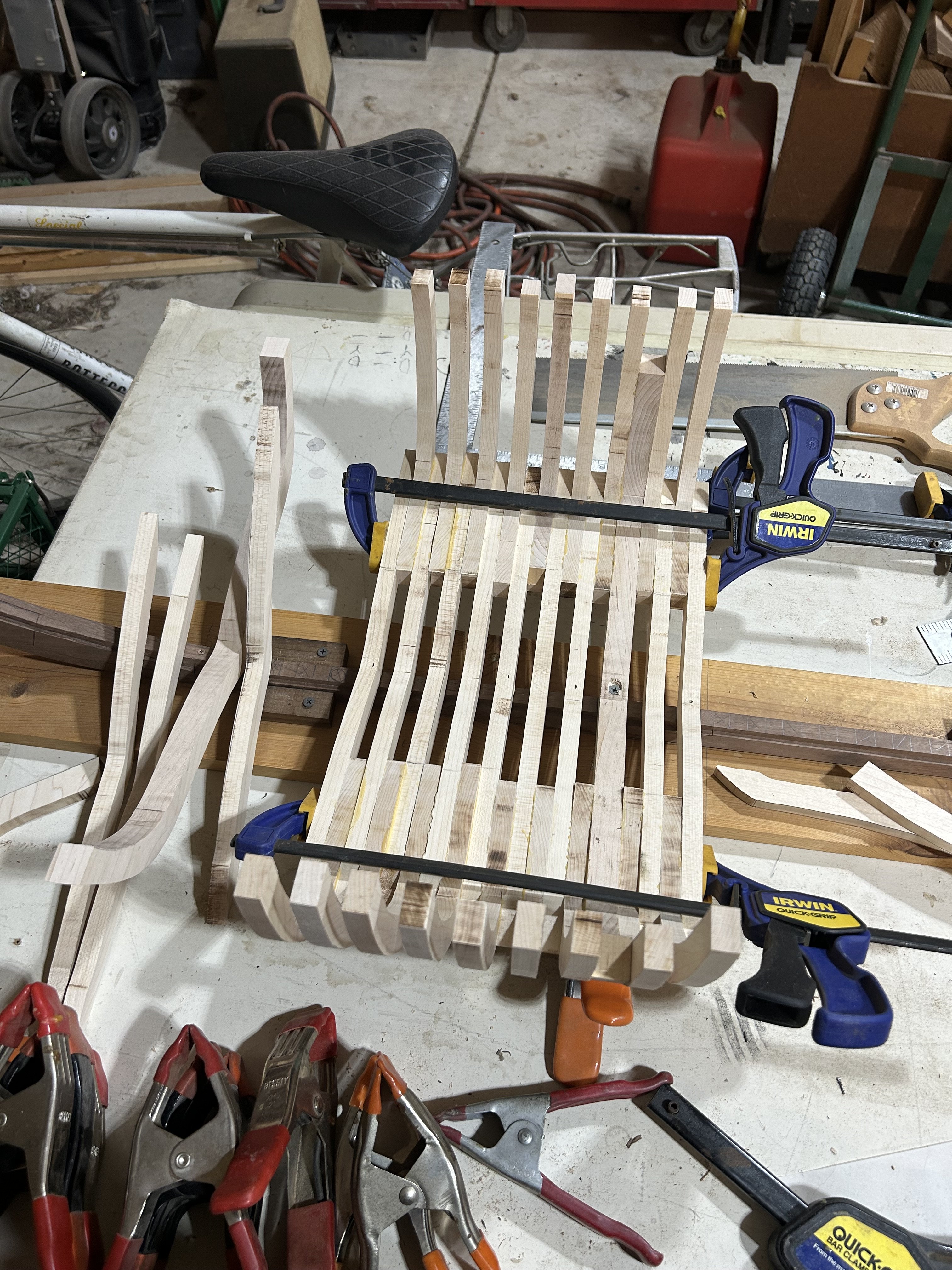
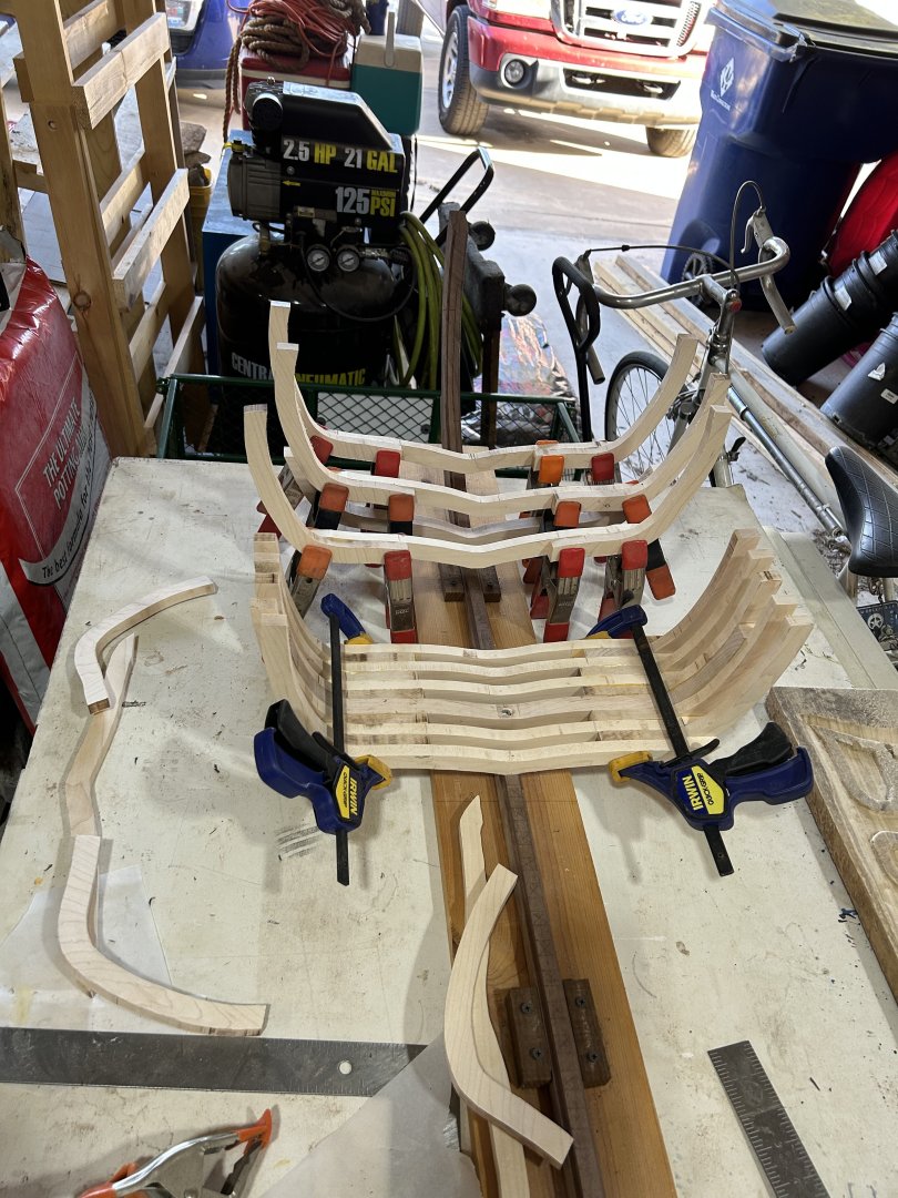
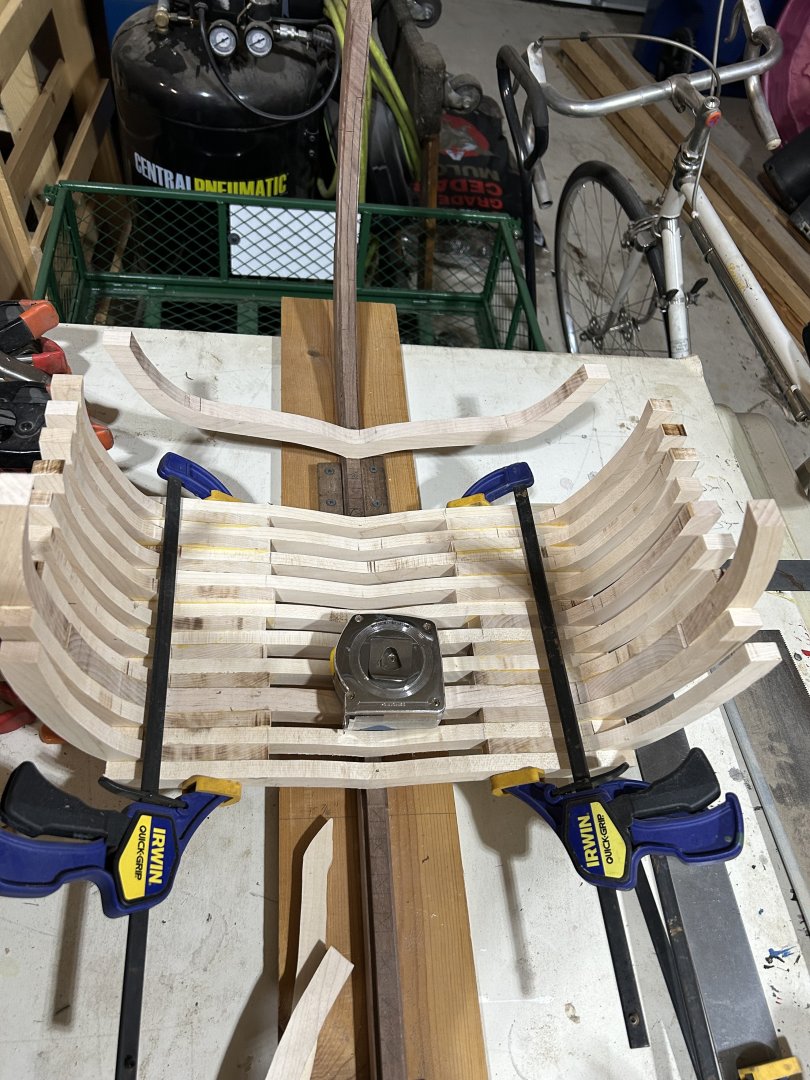
I’ve not updated in a while but work is progressing. Slowly getting frame pieces cut and fit. A long process especially since I have to make my own templates. I am concentrating more on the middle of the hull first as it is easier than the bow and stern. I have begun testing some pieces for those areas but nothing mounted. I included a picture with a 25’ tape measure in it for size reference.


- 47 replies
-
- 13
-
-
As for my model and wood color, it will be more “as launched” than “as salvaged”. I am going to take some creative liberty though and make certain elements stand out more than they would have. Keel, stem and stern posts in walnut along with the wales to contrast against the lighter planking color, still to be determined. As the mast is made up of multiple pieces, I am going to use two different woods with a similar color such as possibly ash and walnut. I also like to model with natural wood colors when possible. As such, something I am considering is using blood wood for the areas of planking that would have been painted red. I’ve done this on other models and I have found it pleasing. A major reason for this is that I intend this model to be educational. By having key components stand out, it is easier for people to see and understand than if they were all bended together. Thank you for sharing those recent pictures and videos link Mike!
-
I do wish the museum would update the plans of the ship with all the new information they have uncovered and mapped since the last set. It is rather frustrating that the most current set is known for many errors. On the plus side, Hocker’s Vasa II book does correct and clear up many issues in the rigging, masts, and other related components. Advances in 3D imaging is also starting to turn out accurately modeled images and the ability to better project hidden components.
-
When I built La Couronne, a French double deck just slightly after Vasa, one of the features that came up was the angle of the bowsprit being off center similar to what is shown in the Vasa sketch. A major difference is that the beakhead remained straight and only the bowsprit angled. I wonder if this was intentional to some degree to angle the bowsprit and finding it easier to angle the entire bowsprit the same. Or maybe only the bowsprit was originally angled but due to the pressures being exerted on the beakhead by the bowsprit caused the entire assembly to warp sideways. That would explain why it appears to be original construction.
-
My intentions are to build her as she would have appeared on the day she sank. To me, Vasa can be considered akin to Apollo 13, a successful failure. Like Apollo 13, she failed her intended goal, to be Sweden's flag ship and display her burgeoning power at see. However, the interest in her after, and the lucky circumstances that allowed her to be preserved underwater, along with the determination to find, raise and preserve her, has made her famous worldwide. I would prefer not to correct those elements that made her. I also feel bad on a personal level about correcting the errors the builders made. In their defense, they built her in the best known practices for their time. These were expert shipwrights who knew their trade well. I believe that the deviations from "normal" practices made were those intended to produce superior results. In a time where trial and error meant building it and seeing what happened, and the as yet not fully understood engineering of building two deck gunships, I think the builders decisions should be maintained. After all, had their gambit worked, we may be studying the fastest two-decked gunship to have sailed.
-
I’m still working on the deck camber. It is one piece of information I have not yet found in my reading. Also major reason these drawings are all in pencil…. From a few interviews that I have watched with Fred Hocker in which the decks are discussed, there does not seem to be much in the way of pronounced camber. It is there, but I’m not sure if it’s a minor rise in the deck such as a modern standard of 2% for drainage or if it should be more. In a couple of papers that I read concerning early 17th century and older warships, there may not have been as much camber as later ships used. Large size ship building practices, especially double gun deck ships, was still very primitive and focus was on figuring out how to support the weight of and operation of these guns. One theory I read is that other than weight deflection, camber was not very important as the decks would be tilted at an angle already during sailing so the water would run to the waterways and be funneled to scuppers or it would drain to the bilge to be pumped out. The ship would only sit flat during a calm when there would be no need for camber. Of course this dismisses a couple of points. The first was already touched upon in that camber would be desired to negate deflection of the deck once the weight of the cannon were added. The second is that the lower one is in the ship, the less pronounced any lean the deck will experience. This would seem to indicate that lower decks would have a greater camber than that of upper decks. Finally, it is mostly that I’ve been too lazy to do the math… 🙄 I have the drawings from the Vasa Museum, (yes they are the old ones as they have still not released an updated set) that do show a slight camber when a straight edge is held under the deck. I merely need to stop looking for an easy answer and do the math. In short, the decks shall bend!! Till then, their flatness is mostly there to help me in finding their heights along the hull for portal placements, wales etc. I’m glad I like research and history because the more I learn, the more I find I still have to learn. 😁
-
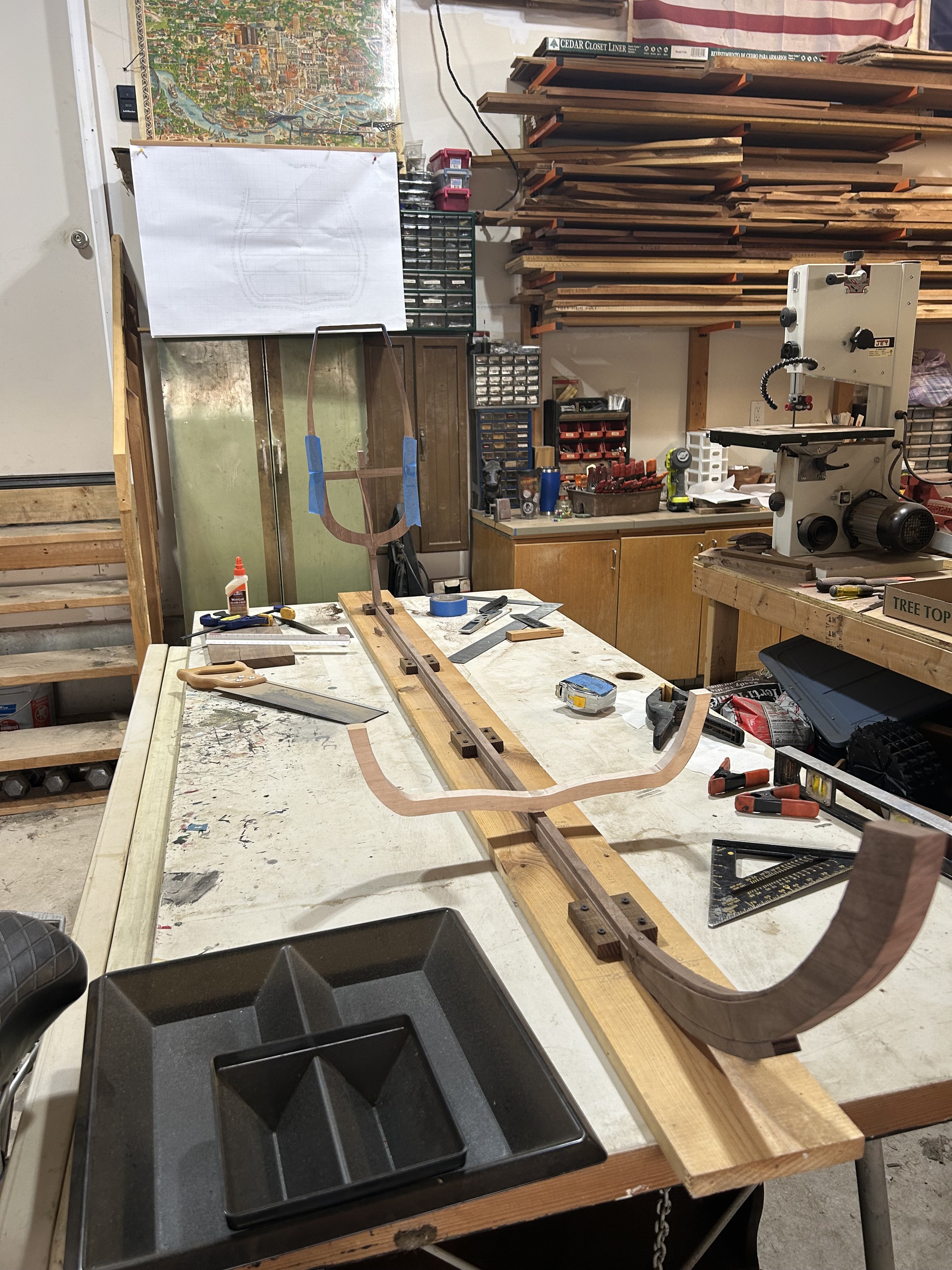
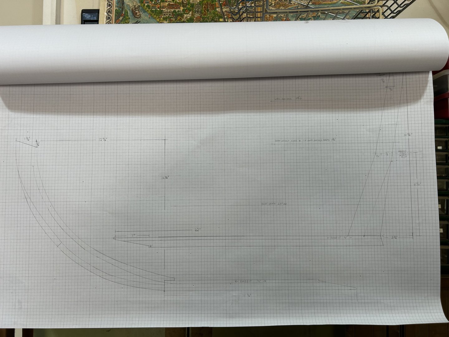
I wanted to share some of the “behind the scenes” work that I’ve had to do. Here are a couple of the drawings that I created to help in design and build. These are made in 1:24 scale on 2’x3’, 1/4” graph paper. I am making one each for many of the key locations on the ship. This allows me to add or change details on paper before committing to wood. Using these drawings I trace out individual elements, such as the frames, onto parchment paper. The parchment paper is then cut into stencils that are laid on the wood to transfer the shape. The stencils are saved incase I need to remake a piece and for creating the additional frames between the key ones. This is a slow process as each drawing takes me anywhere from a couple of hours to days depending upon the level of detail in each one. The two here are of the stem and stern along with the first and last sections of the keel, and the frame that corresponds to the widest part of the ship.

-
I hope so, but thanks for looking out. Sometimes you can’t see the forest for trees and other times you can’t see the trees for the forest. Additional views are always useful and welcome!
-
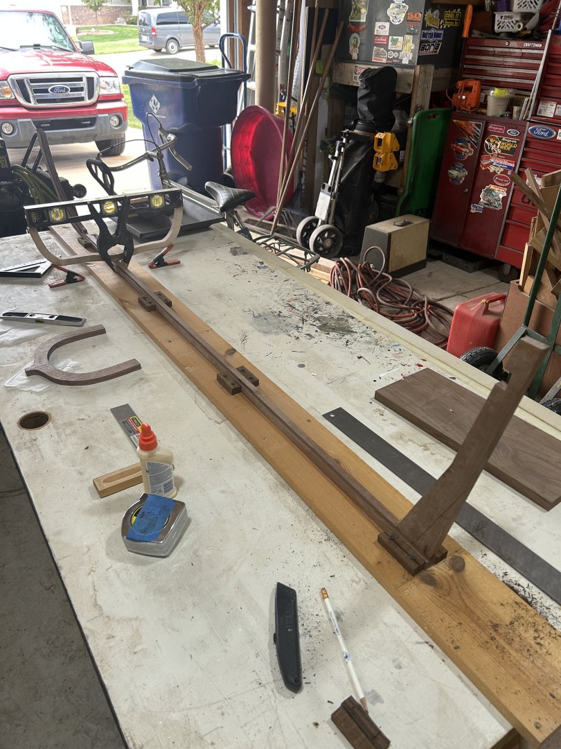
Ah, yes, I understand what you are saying. I thought you were talking side to side, rather than downward with the weight. I was cautious about making sure the board was both solid and flat to not have any humps in it. I think what may be concerning is in a couple of the early pictures it appears that there is a gap under the keel, and in fact there was! The scarf joints caused the keel to rise slightly due to not being cut as perfect mates. This caused the keel to bow upward slightly in the middle. I had to reset the joint, (wood glue truly is strong stuff) and the keel lays flat now. None the less, the concern is genuine, though I admit, I have been focused more on the side to side alignment of the frames and ensuring that they are level across the top more so than deviations at the keel. I have had a few ships with one side slightly higher than the other before, and even once when it looked like the stem and stern had been twisted opposite each other. Typically these were small deviance's and easy to hide, but on a large scale like this, I will not have that luxury as small defects will be magnified. I will take another look at the build board and possibly upgrade it and/or the securing blocks. I admit, I'm a bit more concerned about it now...
-
Your right and this board is only temporary. This one is mainly just for the setting of the keel and frames. Once the frames are set and I can lock them in with temporary battens, the hull is going to be removed from this board and flipped over onto another temporary mount so I can plank the bottom of the hull to the bilge depth. Then the ship will be flipped back over and set into a more secure cradle that should allow me to continue working with stronger support. A final move to the display cradle will take place sometime during the rigging process when I will have to lower the ship from the current table to the floor in order to accommodate the mast height. Likely when I set the topmasts. I'm still working on the final display design as I am not sure just how top heavy she is going to be just yet. Another part of the challenge is that I intend to have a lot of the hull opened on the starboard side to allow interior views. This presents a challenge on where any cradle arms rise so they do not block openings. Fortunately, I have time to figure it out and can make tests and adjustments on the construction cradle.
-
Hi Marc! I'm starting to read back through your log, and after all this time I have a lot of reading! I got to say though that you have not disappointed in your work. She is looking simply amazing! This has been, and continues to be an incredible build with an attention to detail that is unmatched. The level of research and reasoning you undertake in an attempt to make, if not always 100% historically accurate, at least defensibly plausible, sets a high standard in model ship building. I'm looking forward to diving deeper into what I've missed and seeing how it all came together.
- 2,699 replies
-
- 3
-

-
-
- heller
- soleil royal
- (and 9 more)
-
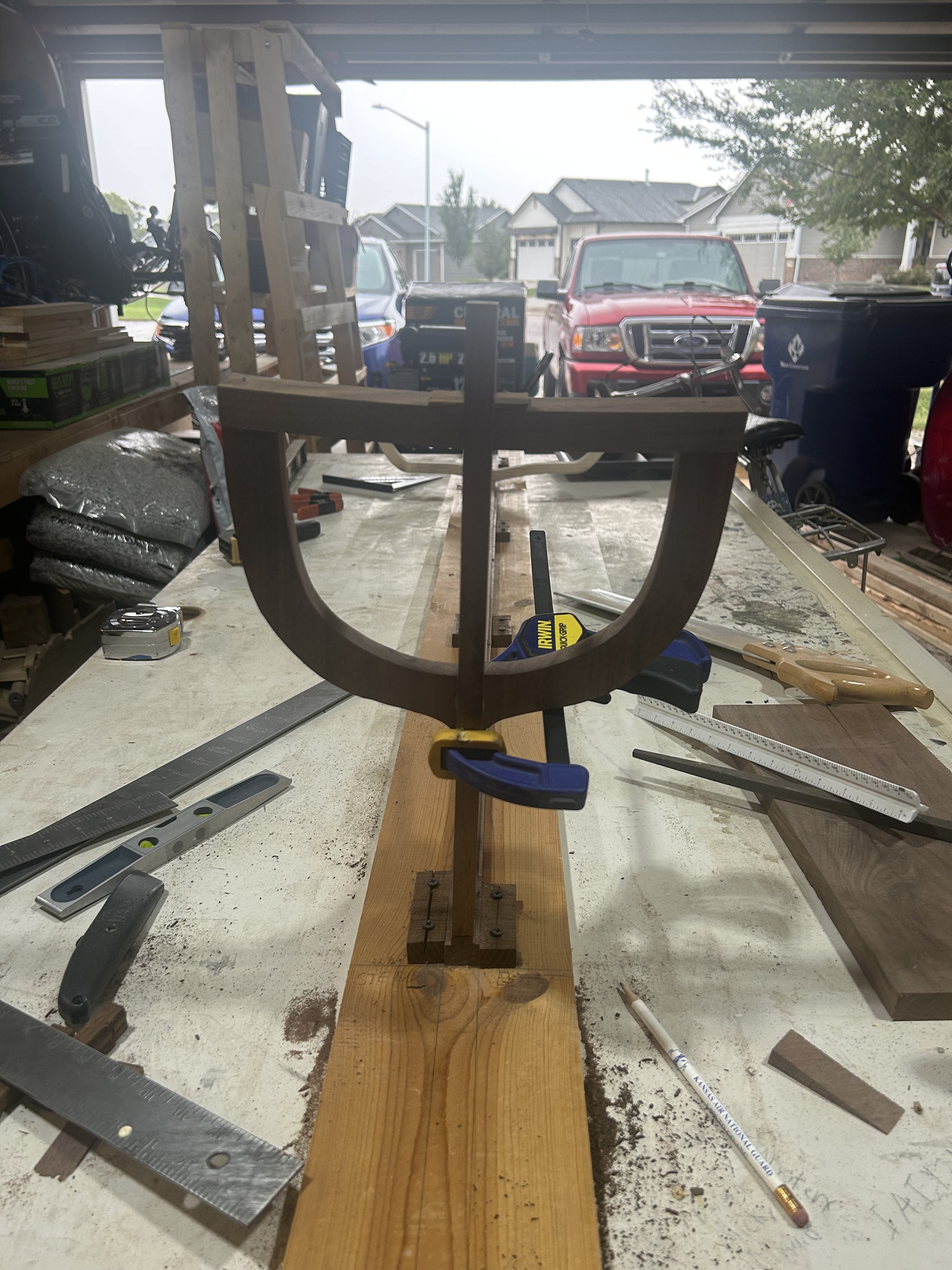
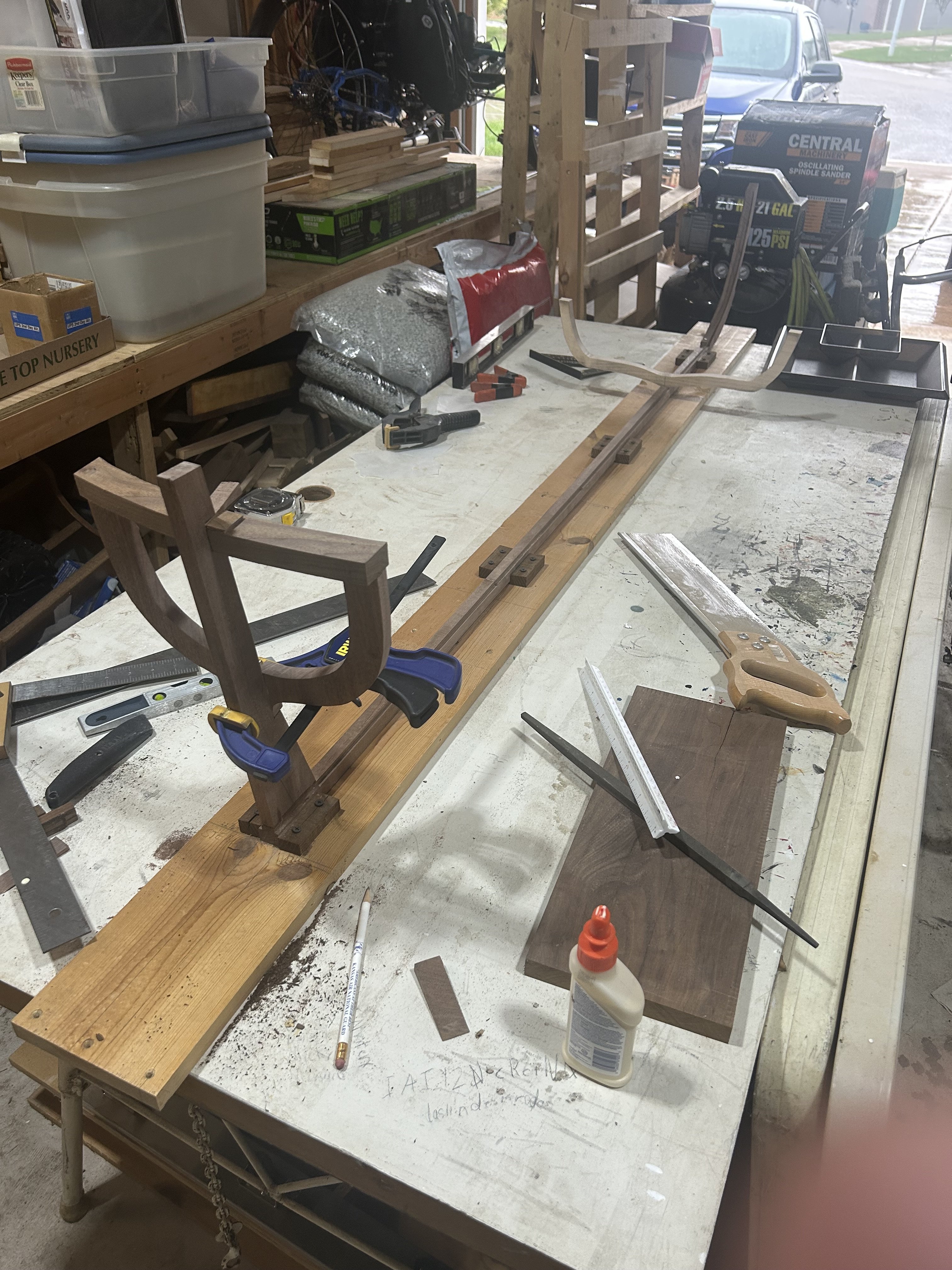
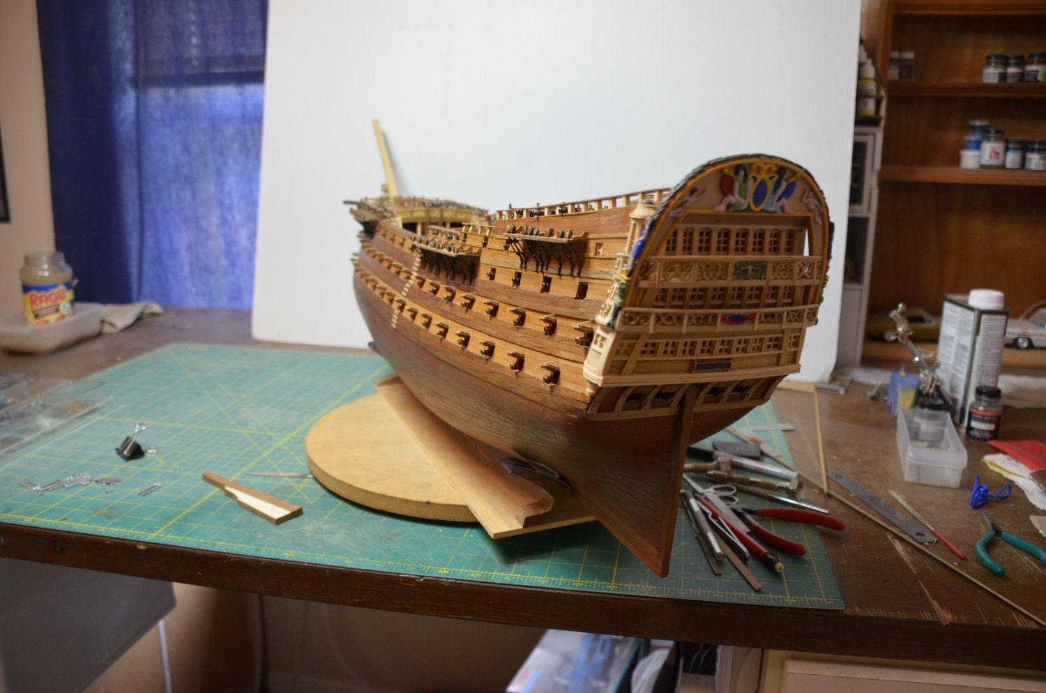
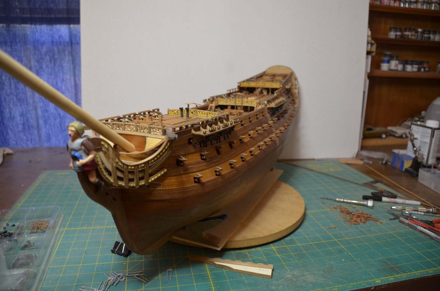
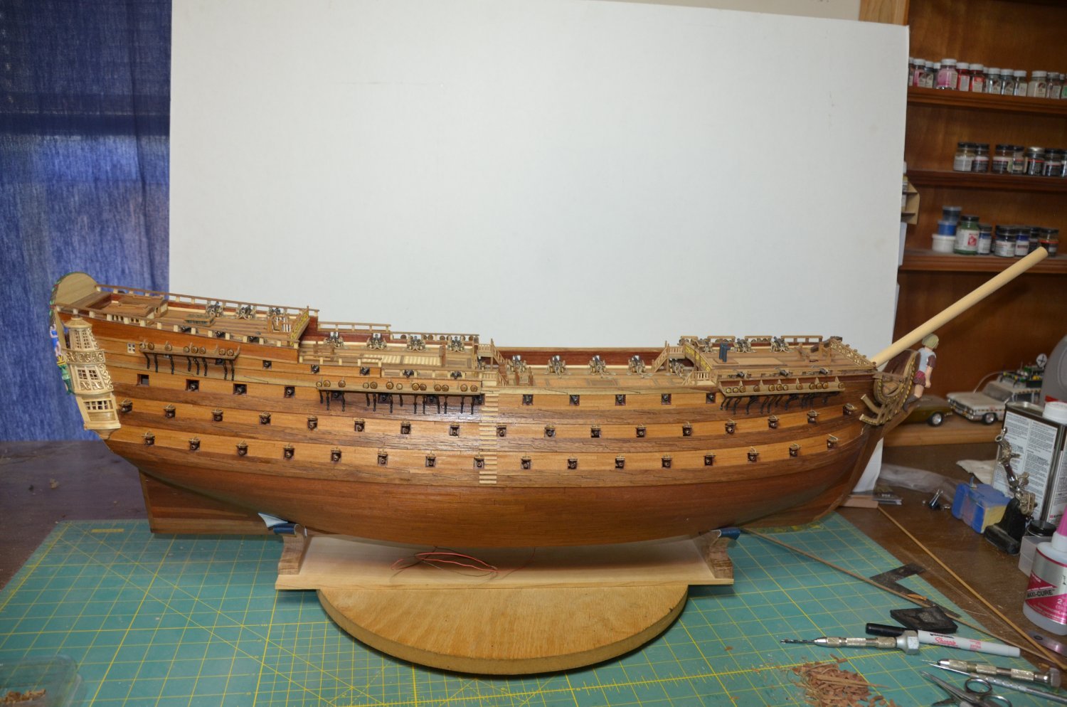
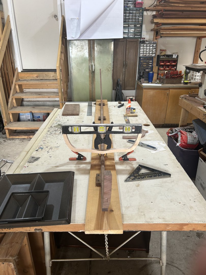
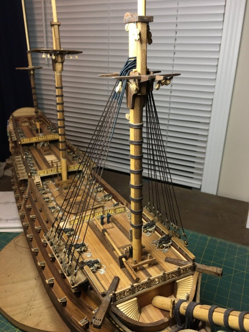
Seeing the Vasa in person is a bucket list item for me. I hope to one day get over there to see her. The transom is taking shape with the wing transom and fashion pieces secured in place. I also temporarily set the stern timbers with tape to give a visual of the height of the hull at the poop deck. With these components in place, a general idea of the final size and shape can be seen. On an interesting note, the Vasa is believed to have been constructed with just these components, keel, stem post, stern post, and transom in place and then the framing set with no frames in place. The planks were clamped in place to each other and then frames were added once the shell was formed. I will place my frames first, but it is an interesting and somewhat intimidating method of construction for a ship this size.


-
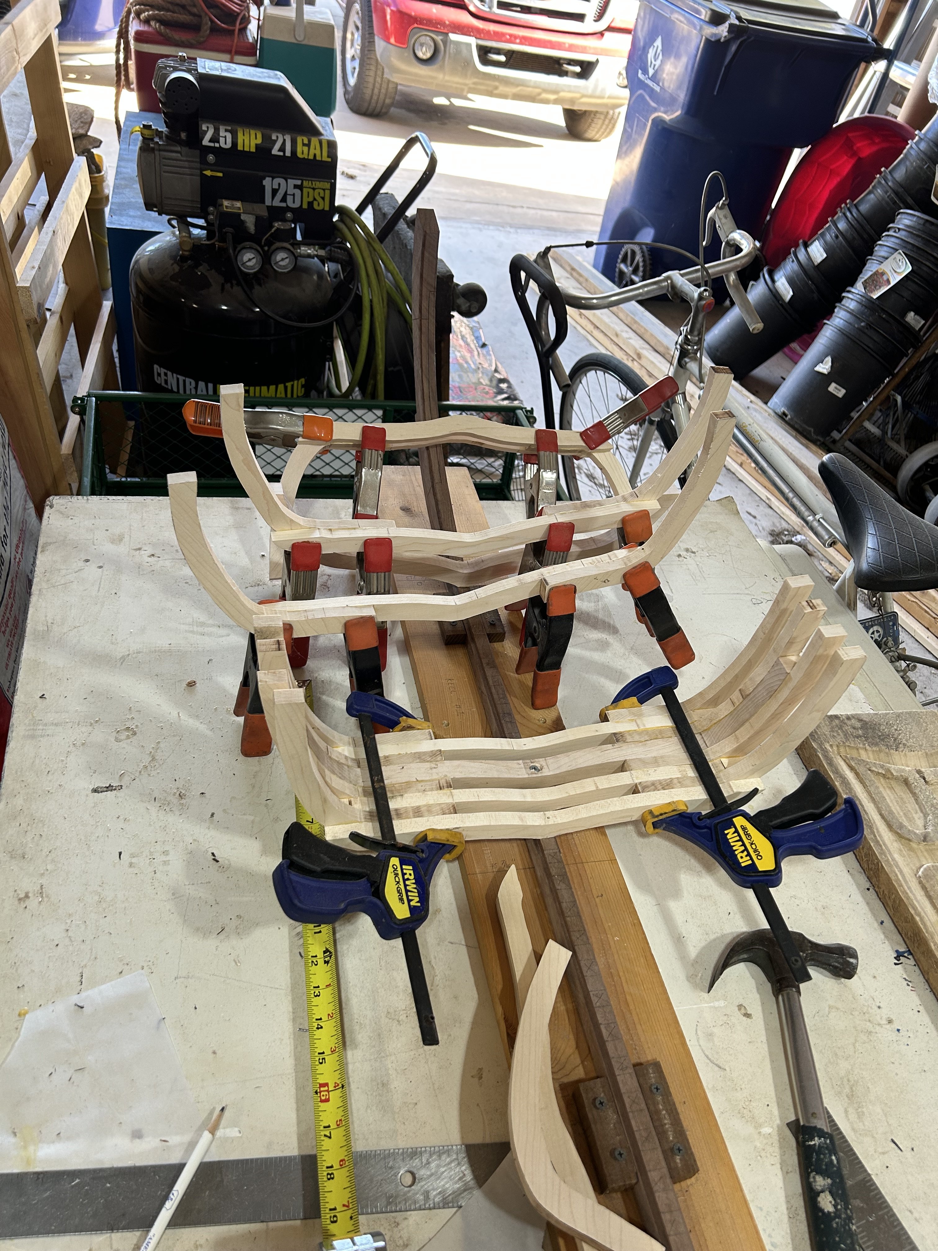
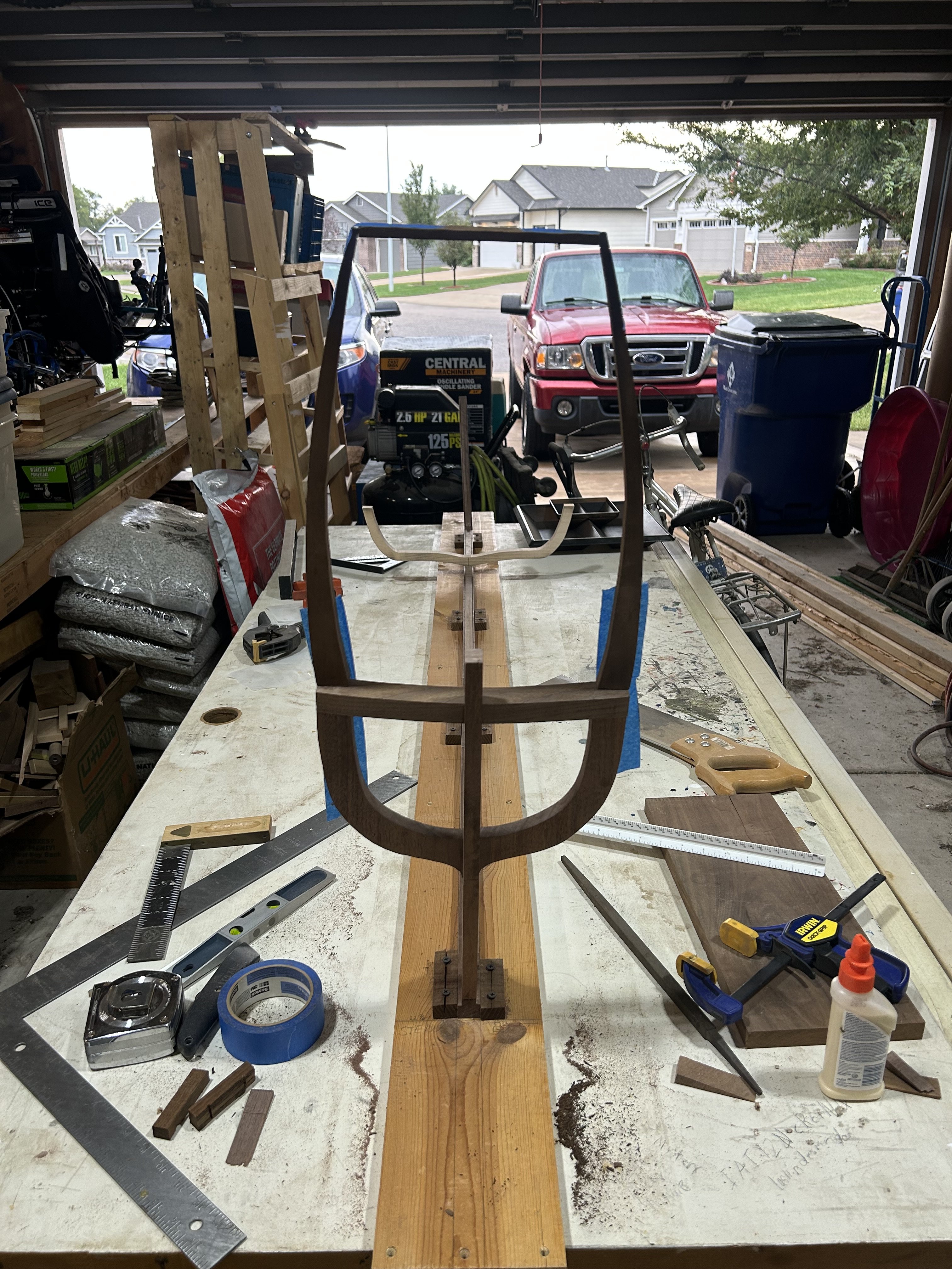
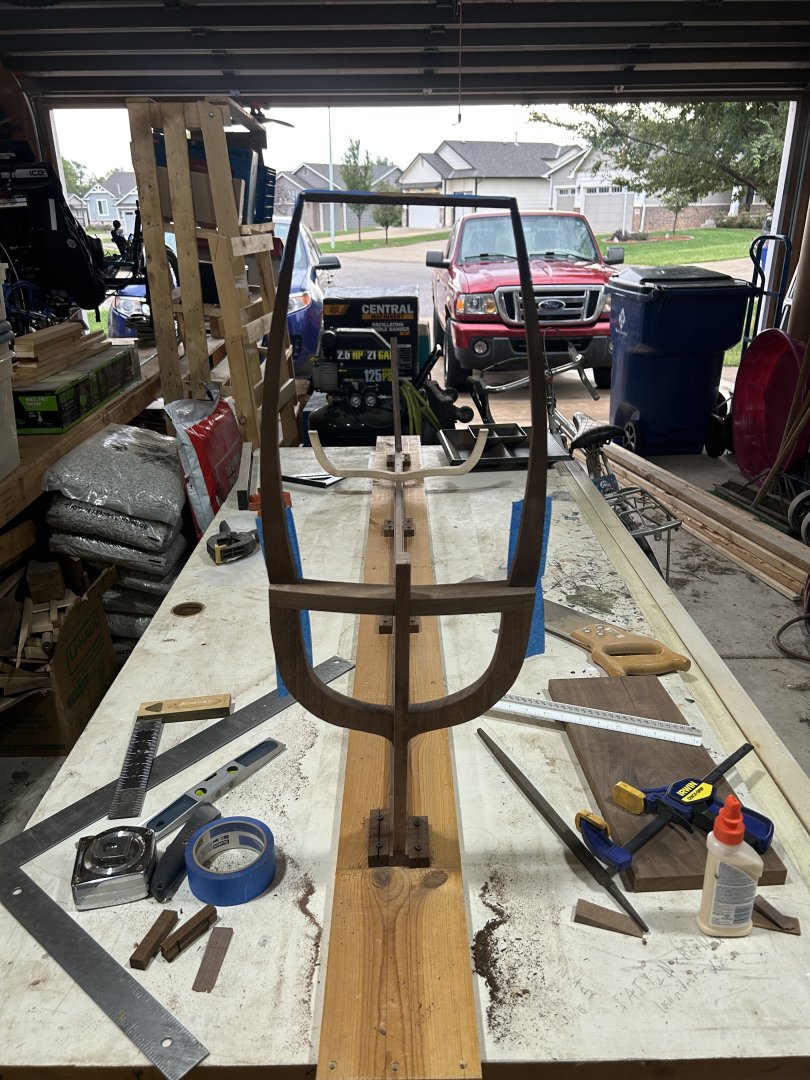
Welcome all who have joined, new faces and old! A few new photos to update a little progress. I built the stem and stern posts and attached them to the keel. The keel, stem and stern are made of walnut as will be the wing transom and fashion pieces. I chose this wood for a couple of reasons. The first and main reason is that I wanted these parts to stick out from the framing and planking. Part of this build is educational and so I want to highlight certain areas and one of the ways to do that is to simply change color. These are major structural components that defined the ship's overall size and shape and as such, they hold particular importance over other components. The second was I already had walnut wood in plenty in the required thickness. 😁 While these parts were drying, I worked on the first frame I would add. This frame is located at the widest part of the ship and once placed would give me a clear picture of the size of the model. At its widest point, the frame is nearly 19 inches. As I am not working with a given set of plans or stencils as many kits provide, I have to make my own. As such, I am making my own drawings for several key frames along the length of the ship. These are mainly where data points taken from the actual ship have been recorded and shared during research and preservation. From there, I can make a series of frames to fill in the spaces. After the frames are installed, fairing can be honed in to smooth out the profile. Next up will be the wing transom and fashion pieces to start building up the stern.

- 47 replies
-
- 15
-
-
I had actually considered modeling it without the topmasts as it is displayed in the museum. That would have allowed me to build at 1:10 scale even, but, having read through Hocker's Vasa II book which goes into considerable detail on the rigging, and from personal experience with complete rigging and sails on previous projects, I want to try for full rig. I have ambition of going so far as to make the rig semi operable for changing position of the sails, but that may be a dream. Either way, its a long ways out.
-
Hi Jan, yes, I am a member of that forum as well. It is a wealth of information, but as you said, mostly inactive. I think most of the members have moved on either to other projects, lots of unfinished logs, or other forums. Here and SOS. It is a shame as it was a good place to get accurate up-to-date information directly from Hocker. I've been told that he will still answer direct messages.
-
Thanks Thomas! I am not planning on displaying this in my home. Already have a few not as large models taking up room as it is. A am actually talking to a friend of mine that manages a library to display it in. They are planning a remodel and expansion in a couple of years and would like to potentially have it as an "attraction". I told them I would donate the ship if they can help with a display case. I also said it will likely take me a couple of years to get it built, so that will work with their schedule. We are still working through some details but hopefully it works out. This will not be my first long build. I've done a few, though it will be the first 100% scratch build, so a lot more work involved than normal. As for materials, the wood I have in supply, except for a few things that I have a local source for. The cannon are still up in the air for sourcing but I have time. The ropes will be interesting to make, but I've made them before for other ships, I will just need to upscale the process. I actually love the fact that building in such a large scale ties in closer to actual building practices. This is something that I have been wanting for many years so I'm looking forward to it. As far as perseverance, that is something that I love about our MSW/NRG community. We help to motivate each other through our passion in these vessels. I have made some good friends on here, and when things fell apart a couple years ago and I stopped posting, I had a couple of them reach out to me just to make sure I was okay. I have actual family who didn't bother. This community is wonderful. I've missed it and am glad to back actively among you all.
- 47 replies
-
- 11
-
-
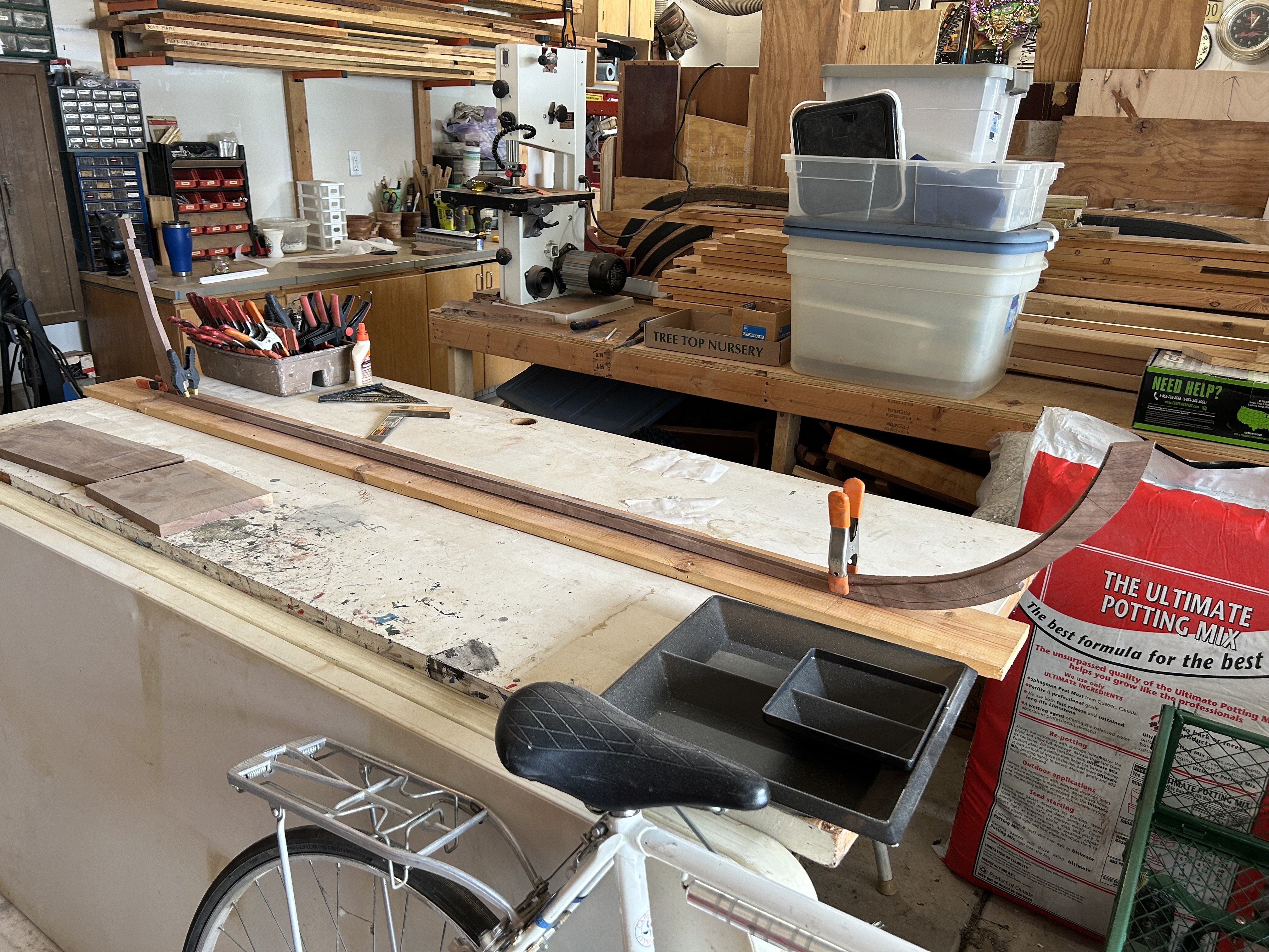
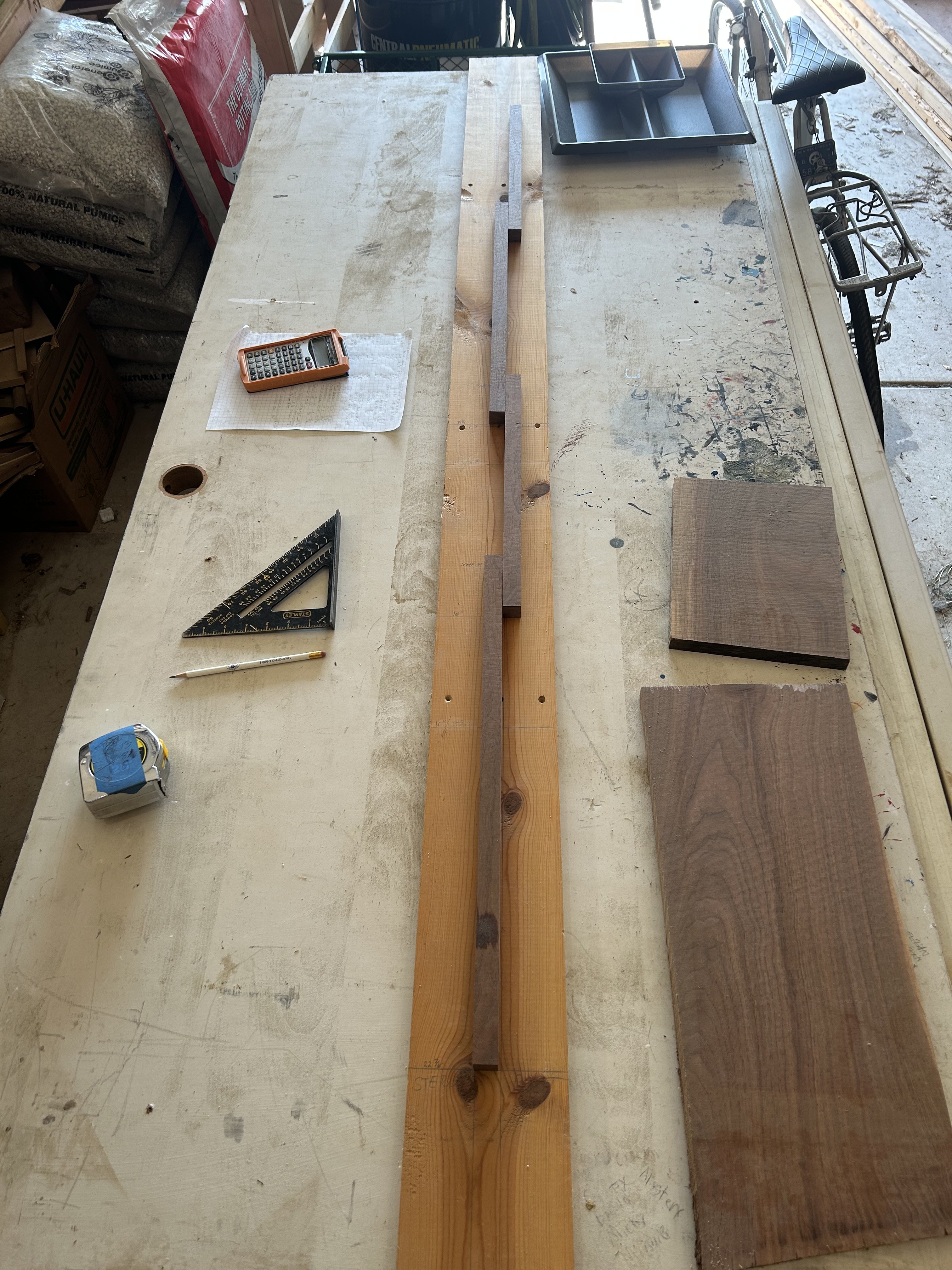
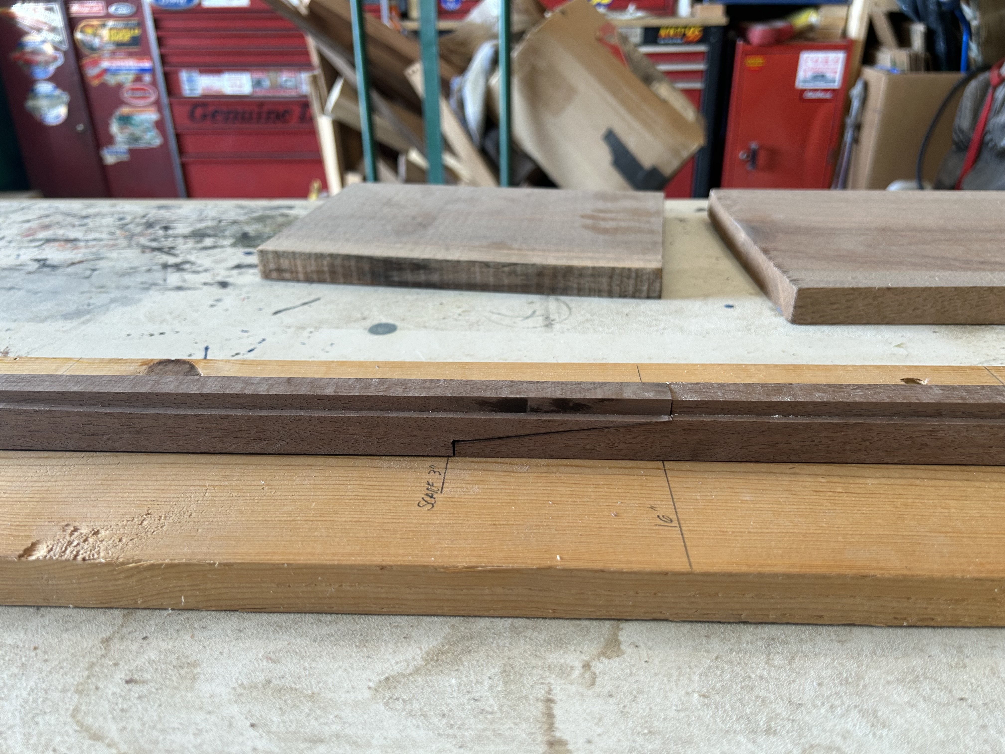
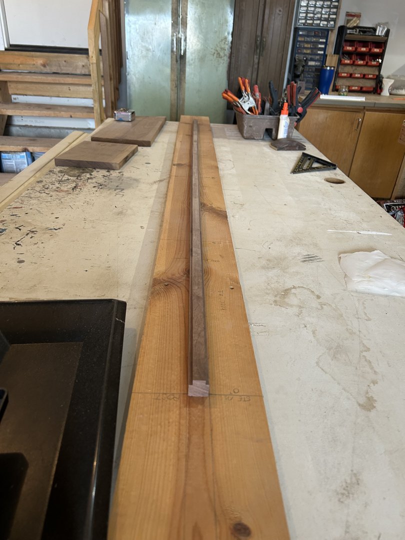
Construction started with laying out a build board with marks for the keel sections. This gives me something to map the build to as well as provide support while building. I chose to model the keel in four separate pieces as the actual one is. Each piece is a different length and here we run into of the first major deviance from generally accepted practice. The main mast is stepped above a scarf joint at section 2 & 3. Typical keels of the time would have been made in three sections to avoid this by stepping the mainmast in the middle of the 2nd section. The accepted reason for this deviance is the Dutch shipbuilding practice that attempted to have minimal waste by using as much of the available wood as possible. Therefore it is believed that at the time of sourcing the wood for the ship, along with the other ships under contract at the time, this was the best they could do with minimal waste. We do not know if this would have truly mattered or not, as the ship was never able to truly put any strain on the joint. Once the sections were cut to length, the scarfs were cut out and the rabbet was grooved onto the sides. The pieces were glued together and left to dry. The overall length of the keel alone is 5'-4". Next up will be stem and stern posts.


- 47 replies
-
- 14
-
-
Hello all! After a very long absence I am back. The last few years had a lot of unexpected twists and turns that took me away from ship modeling. Life has calmed back down and set me to follow one of my long-time dreams of building a very large, scratch built model ship. I debated for a while about what ship it would be and what scale I would use. I wanted the opportunity for lots of details both outside and inside the ship, however, the model also had to fit within the confines of my garage and be able to pass through the overhead door. I decided upon the Vasa for a few reasons. The first was that I wanted to stay within the 17th century as I love the look of those ships. Second, I have not built a model of the Vasa, and the third, and most important, is the vast wealth of knowledge available about her. While I do not claim that every component will be 100% accurate, I intend to get close. With the ship selected, scale came next. I wanted it to be as large as possible, but still able to pass through the overhead door. This restricted me to 7'-2" of clearance. 1:24 is the largest scale that I can use to allow for the ship's masts to be fully rigged as the top of the flagstaff on the mainmast will be right at 7'. (I may make this part removable to give myself a little extra room for the day I have to move it.) Finished, the model will be about 9' in length, 7' in height, and a little over 2' in width. My next challenge was drawing up plans for the main components, keel, frames, transom, etc. Using several sources, including the Vasa museum, books by Fred Hocker, and a brilliant dissertation on Vasa's architecture by Kelby James Rose at Texas A&M, I was able to get accurate dimensions, angles and curves on the main components, as well as pictures and explanations on what the internal structure looks like, details on construction joints, and functions of many elements that are not always shown on typical models. One of the major issues that I've run into is that Vasa was not built along the typical guidelines of the later 17th century. Many deviations in the Dutch building practice along with changes that both builders, first Henrik Hybertsson then after his death, Hein Jakobsson, made to the structure mean that some of my usual resources that I use for 17th century ships, will have to be dismissed as they are not applicable. Fortunately, while I strive for accuracy, this project is most importantly about fun! I used large graphing paper to draw up 1:24 sale drawings. This is allowing me to test fit elements and see how they interact before cutting them on wood. I can then trace out the individual pieces that I need onto parchment paper to use as a stencil to transfer the shape onto wood. This is especially helpful on the curved parts. It also allows me to try to make my mistakes on cheap paper rather than expensive wood. I started this project technically in May with the drawings, then I cut my first pieces of lumber on September 7th. This is likely to be a very long build, but I really don't know of any other kind! I hope you all enjoy this as much as I do. There are still lots of things I've yet to figure out such as how I will make the cannons and all the carvings, plus how much of the interior I plan to show. I have a rough plan, so we shall see. In any event, it should be entertaining.
-
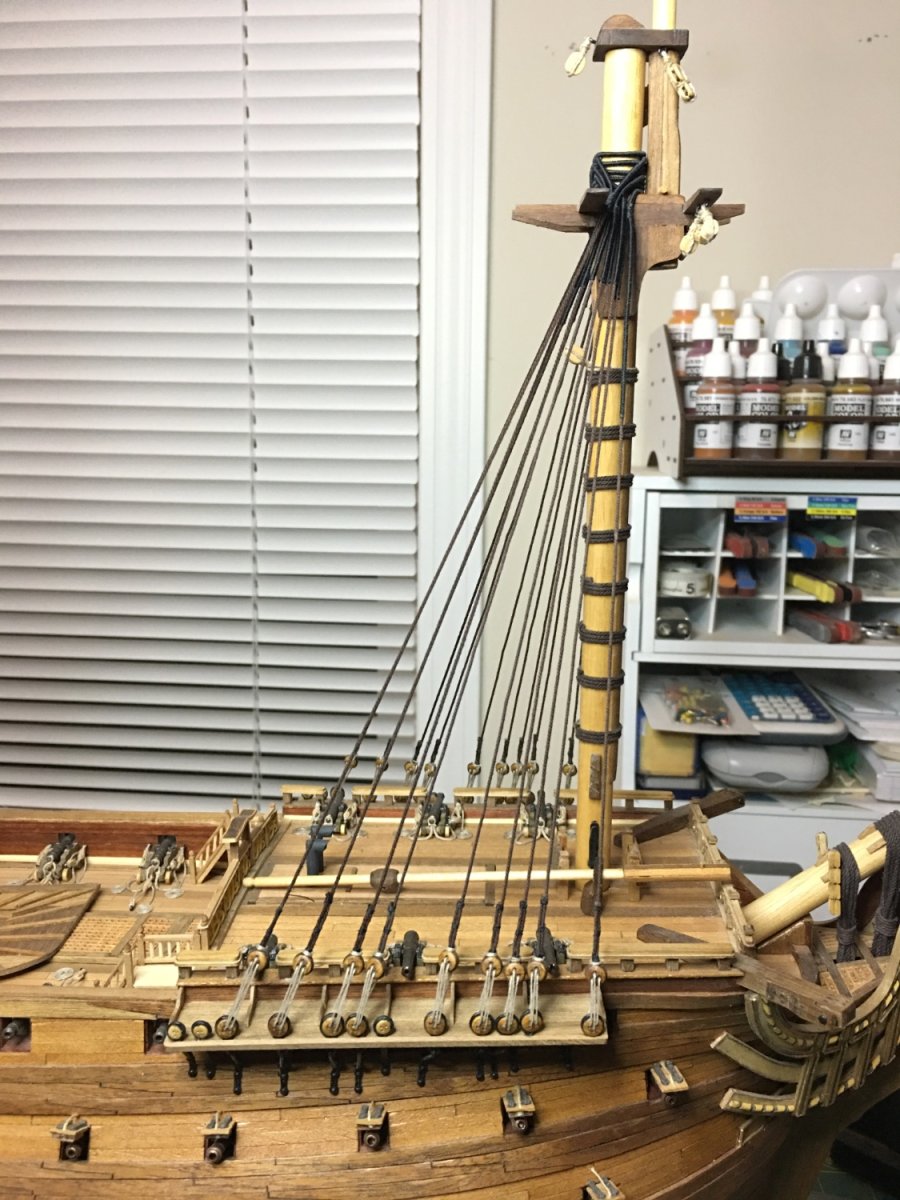
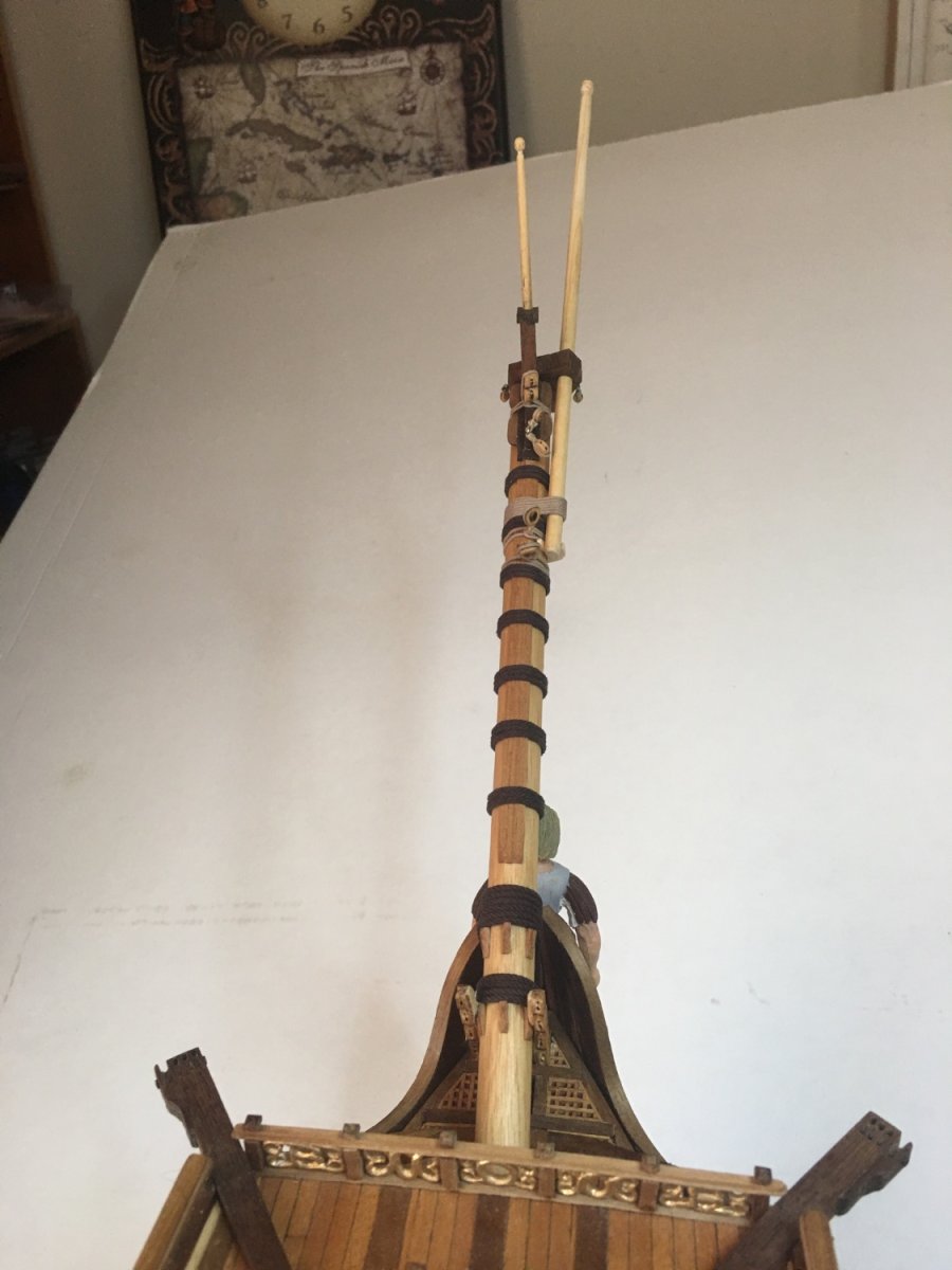
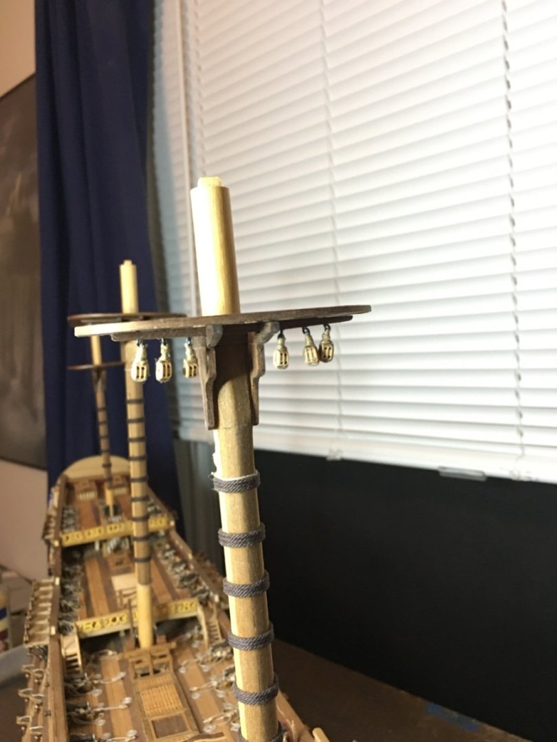
Lower foremast shrouds are in place. Ratlines are up next.

-
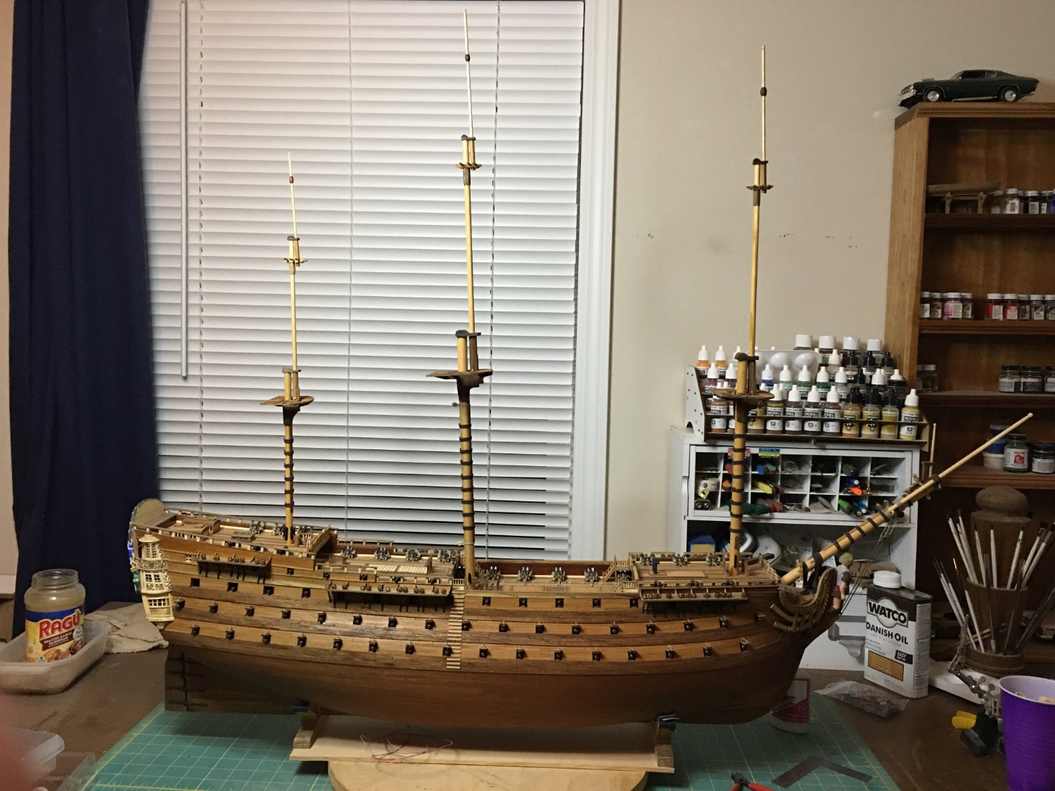
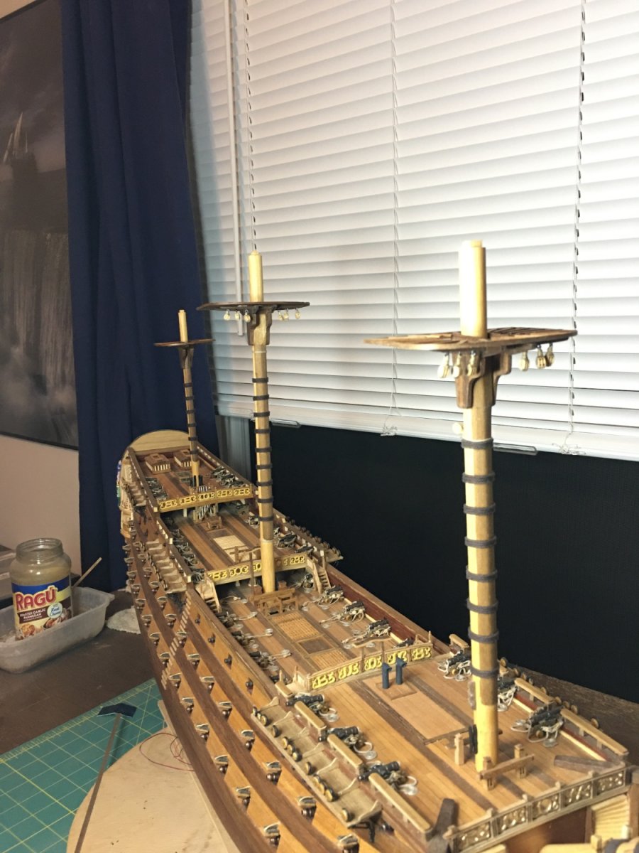
All three masts are topped out and Royal Louis has reached her full size at 33 inches tall and 43 inches long. This is another massive model. I will be working on attaching more blocks to the masts, tops, and crosstrees then will begin installing stays and shrouds.

-
Finally getting back into the shipyard. Should be much more regular with updates again and I am ready to build! While I have been busy over the past few months, I have managed to get in small bits of build time and have been particularly active this week resulting in all three lower masts and tops built. Neither masts nor tops are glued yet, just rough fitted. I will build all the masts, caps, crosstrees, etc. then switch to rigging. After all this time it will be nice to start going vertical.


-
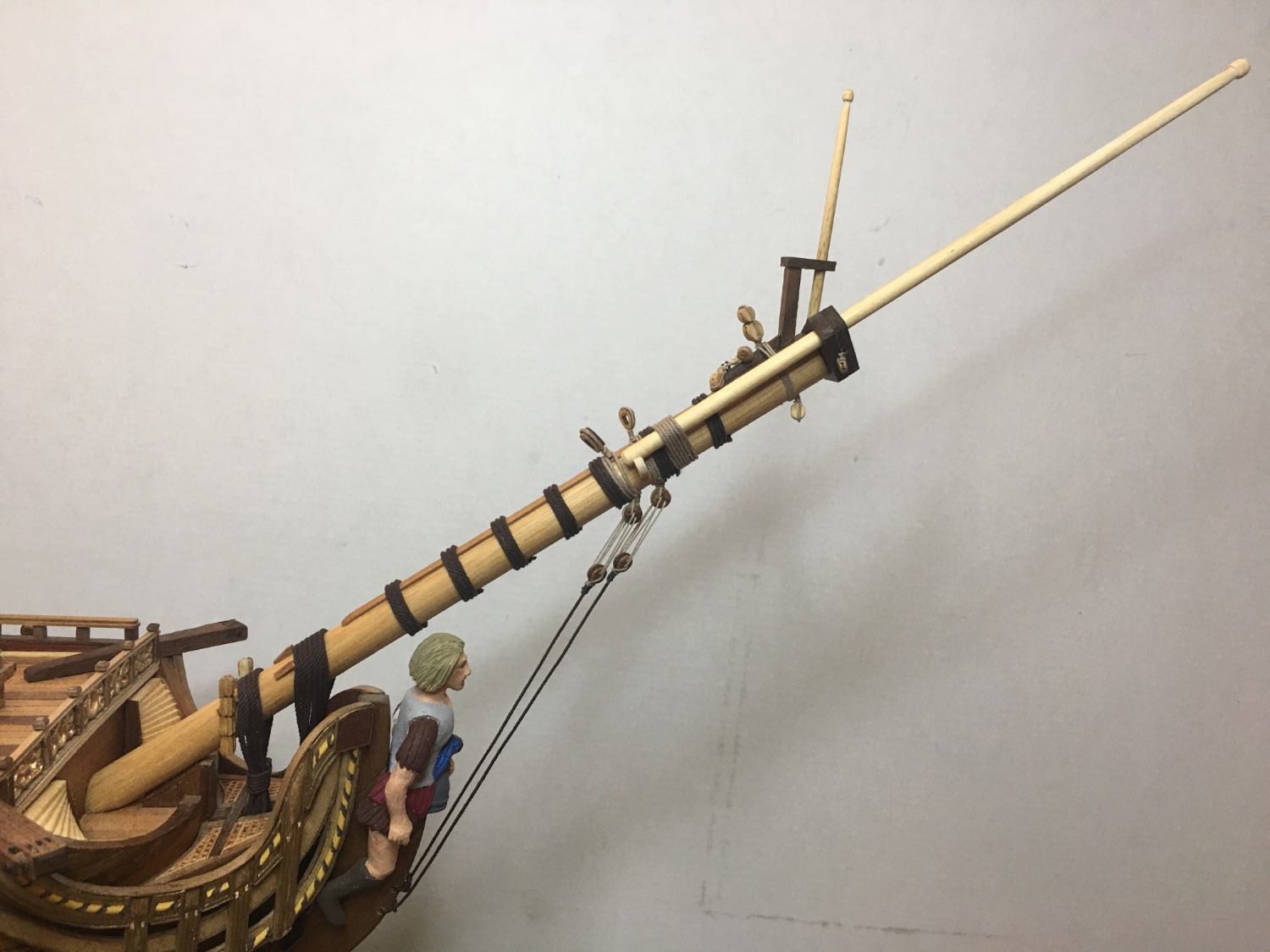
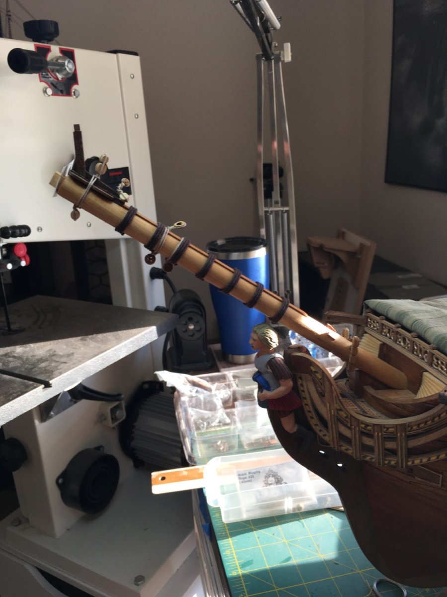
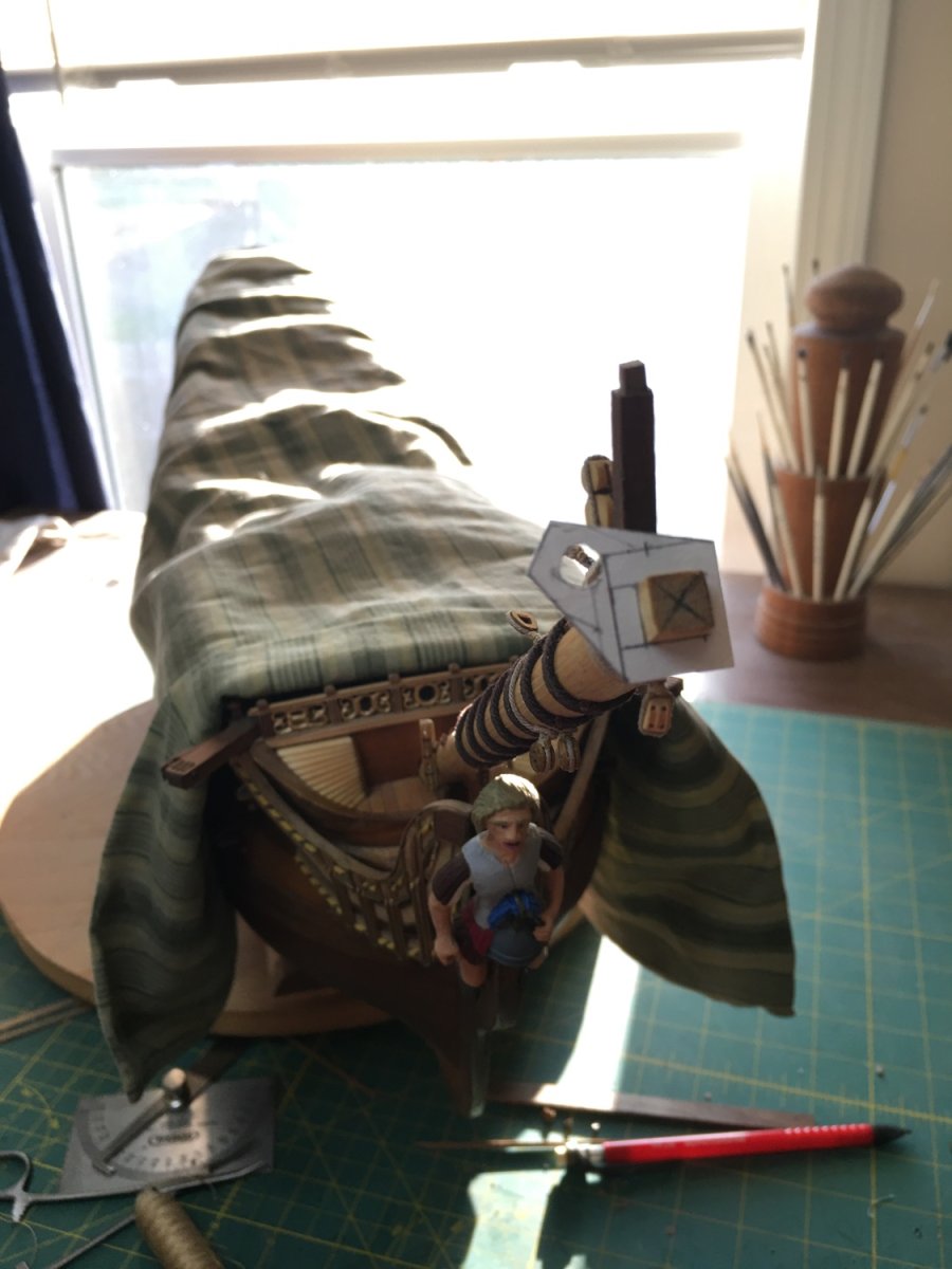
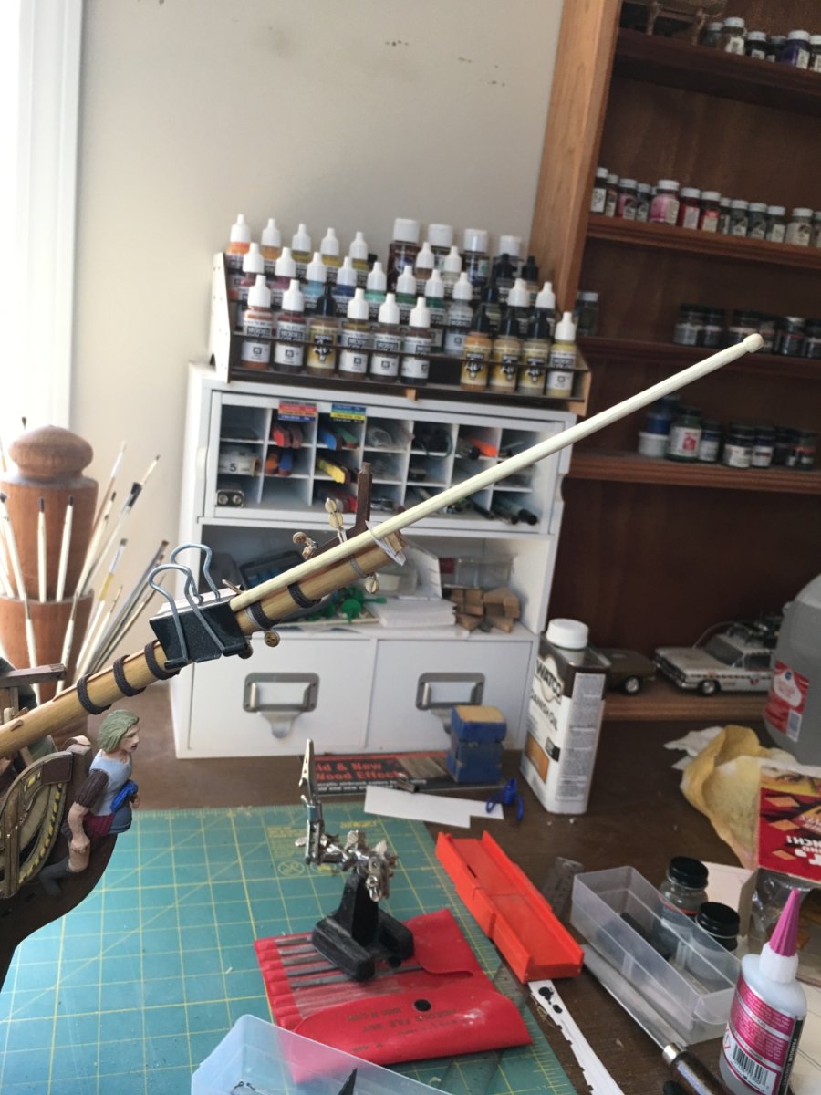
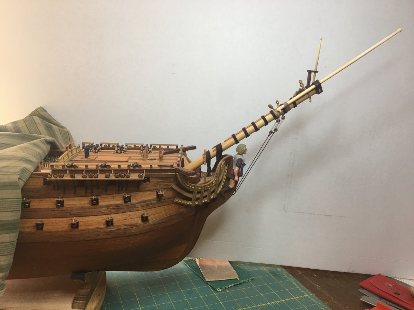
Bowsprit assembly complete and installed. Missing a few blocks still but those will install when the rigging commences. Foremast up next.


-
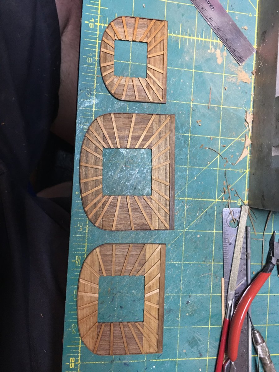
Some work on the bowsprit mast. As with all masts and yards, I’m trying to attach as many blocks and other components as possible before securing to the ship. This is made trickier as I intend to have sails but of course the rigging plans do not include that information. To figure out what is needed, a lot of consulting other books and examples is taking place for each sail to try to find all the components needed. Even more fun is that I am used to building ships with spritsail topmasts, and this one has a jib boom and sail. My accumulated knowledge of the former is not helping right now…


-
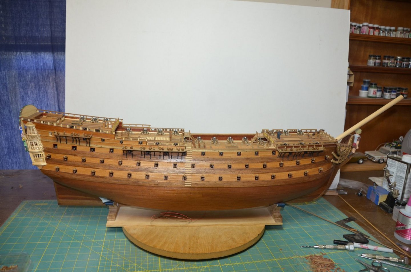
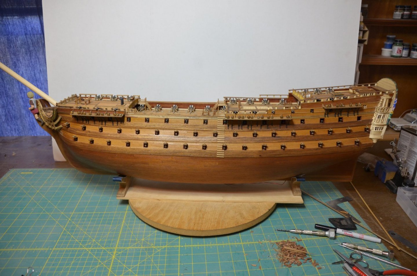
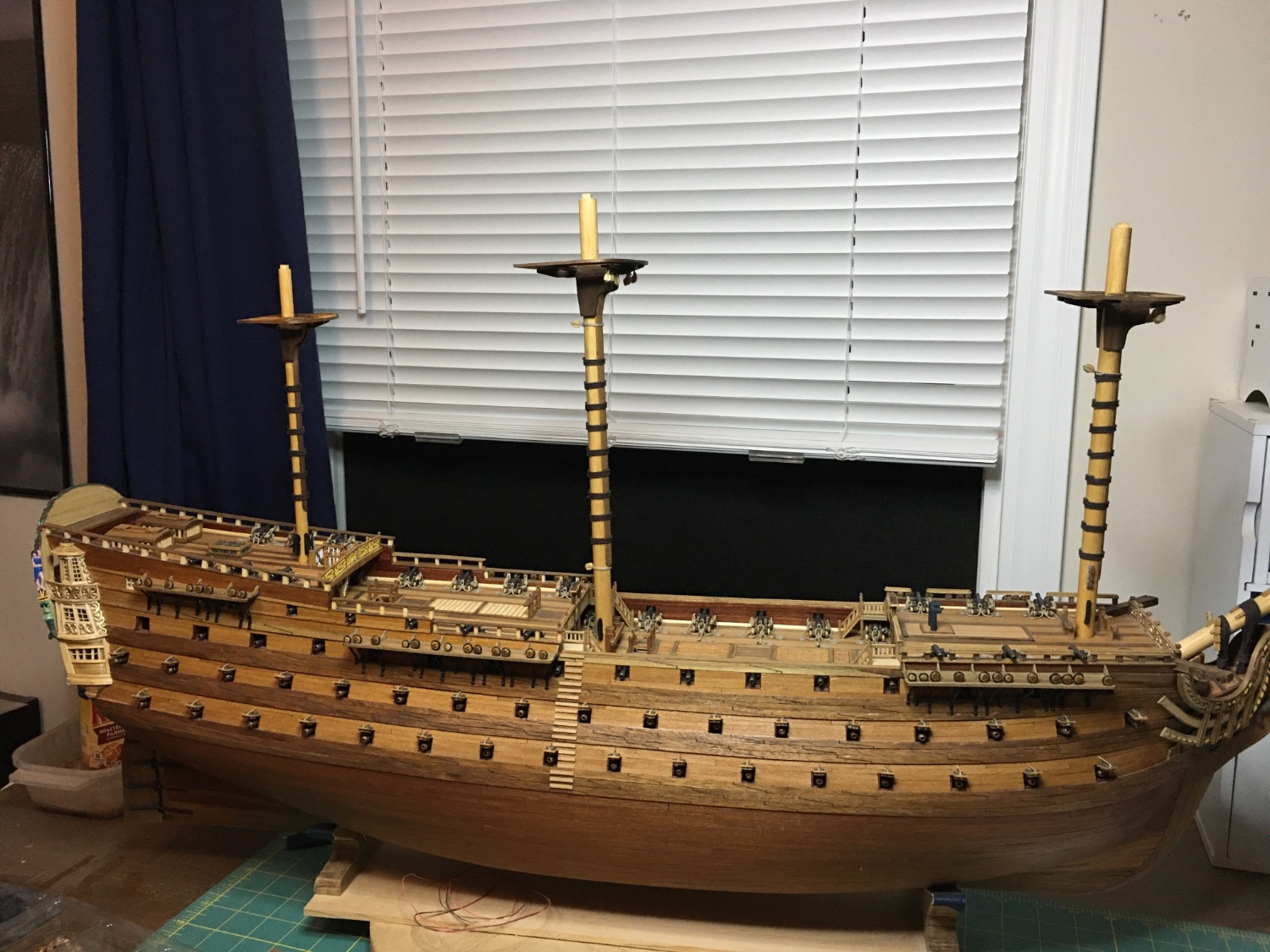
Marc, Vic, thank you very much. Still very busy but I've managed to get in some build time and finished installing the gun port lids and canons. A couple more items and Royal Louis will be ready for masts and rigging.