HOLIDAY DONATION DRIVE - SUPPORT MSW - DO YOUR PART TO KEEP THIS GREAT FORUM GOING! (Only 53 donations so far out of 49,000 members - C'mon guys!)
×


AntonyUK
-
Posts
1,190 -
Joined
-
Last visited
Content Type
Profiles
Forums
Gallery
Events
Everything posted by AntonyUK
-
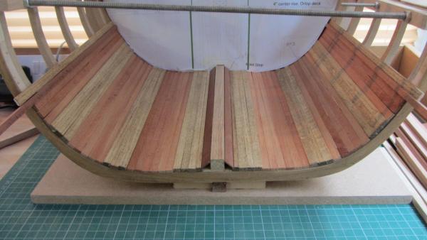
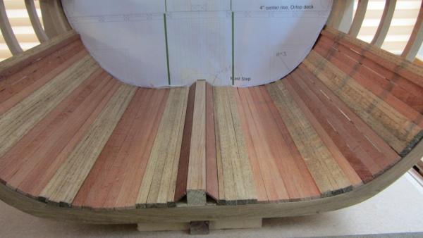
 Hi. Thanks for the reply Kester Just added 2 more drawing of the deck layouts. Thanks for looking in Regards Antony.
 -
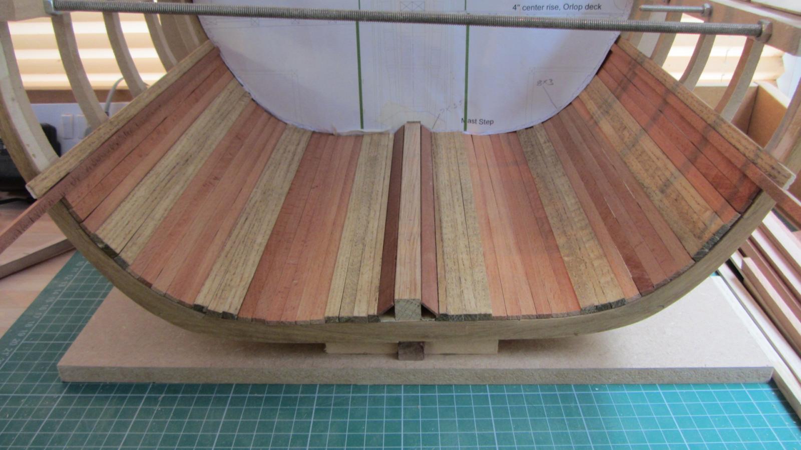
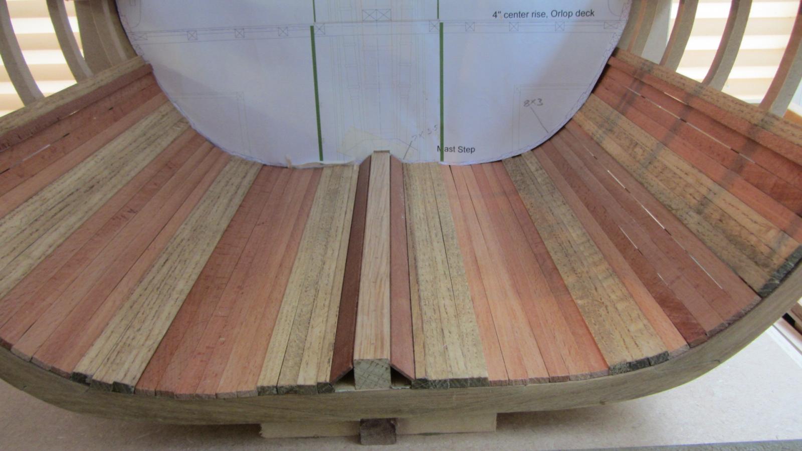
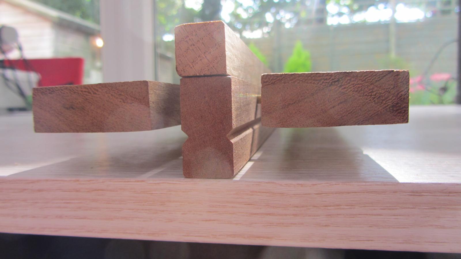
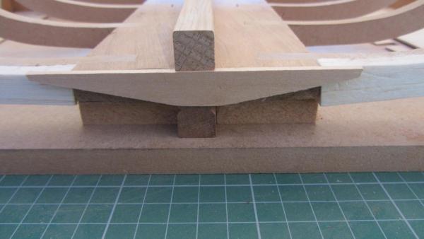
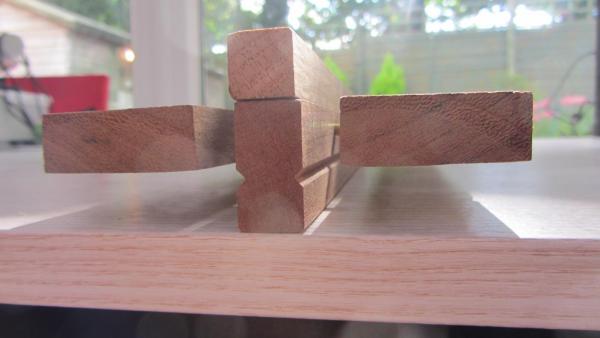
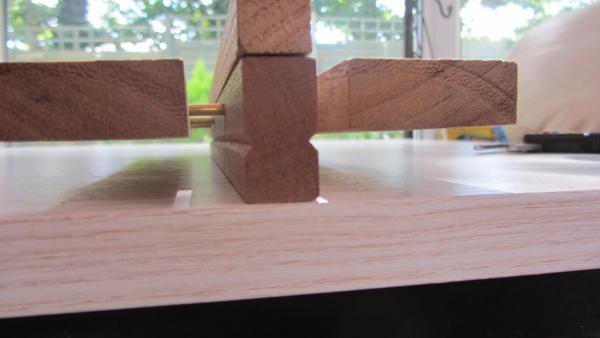
Hi. Two photos with the timber cut to length and coloured with Oil and dye. Also have Backboard with section plan in place to check square and correct placement. Regards Antony.
-
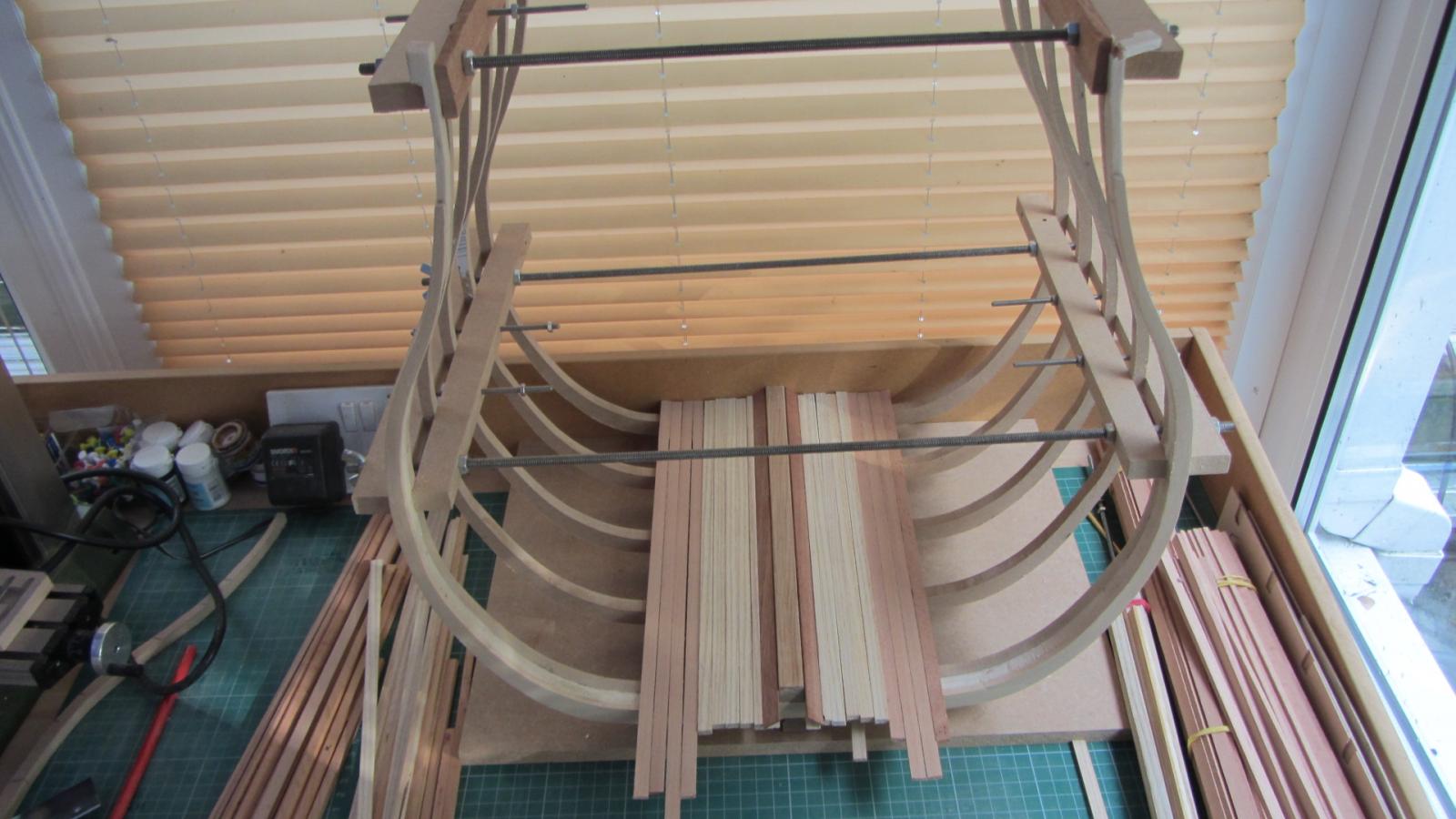
Hi. Almost ready to lay the timber up to the Orlop deck height. But I have a question :- Caulking Is it only the exterior and the weather decks that get caulked on the victory ? Have read through the books that I have and it's inconclusive. So should I simulate caulking on the hold timbers.? Many thanks Antony.
-
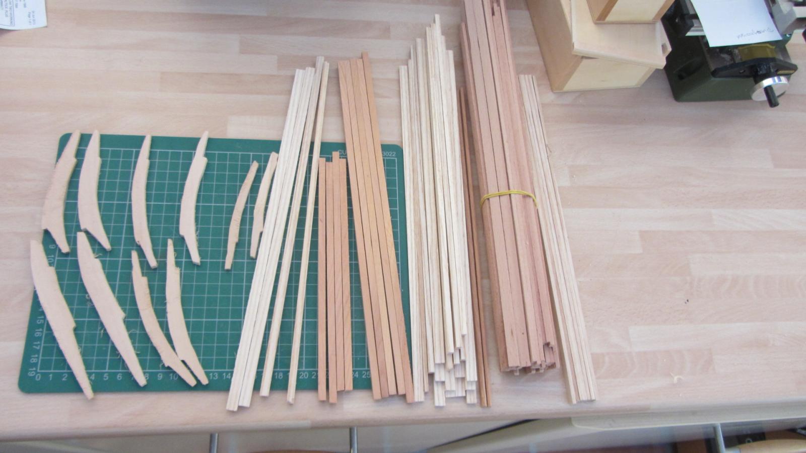
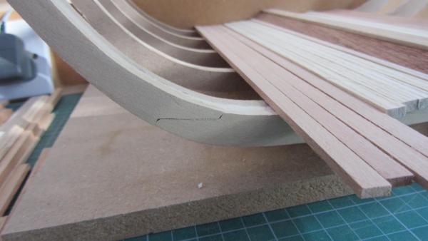
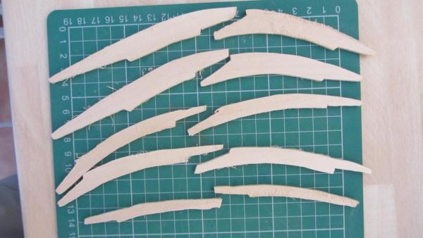
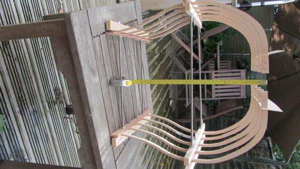
Hi. Another step done. A Photo with the ship on my 14 year old lads Wheelchair tray. for Yves. Close up of the frames. The timber cut and ready to put into place. I will colour the timber before fitting (not sure yet on what colour/stain). More as I progress. Regards Antony.


- 209 replies
-
- 10
-

-
Hi all. Thanks for the welcome. I will stop with a stub mast as the area for the display is max 1 metere square. Might consider doing a drawing of the mainmast and the standing and running rigging if wanted. I will take a photo today for you Yves. And post it tonight. I will continue adding details into my drawings as I progress. The deck plans will be next to be drawn. If I have drawn in any errors then please tell me. No I won't growl at anyone Regards Antony.
-
Hello Alexandru? Still following this wonderful build. You are making a perfect model and your joinery is excellent. Regards Antony.
-
Hi Wayne. Thanks for that. Never gave it a thought that it would be the same as uploading a picture. Regards Antony.
-
Hi Joe. The Solidworks is nice but it's not easy so I went over to Illustrator and got on very well with it. I will load up the PDF files later on. Regards Antony.
-
Hi. Cane someone please tell me how I can Add a PDF file into my posts. Just started a new build log and would like to post the drawings. http://modelshipworld.com/index.php?/topic/3593-hms-victory-cross-section-by-antony-scale-136/ Many Thanks Antony.
-
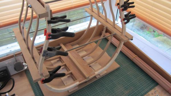
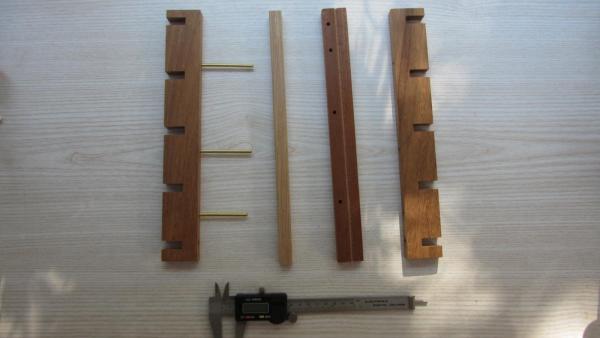
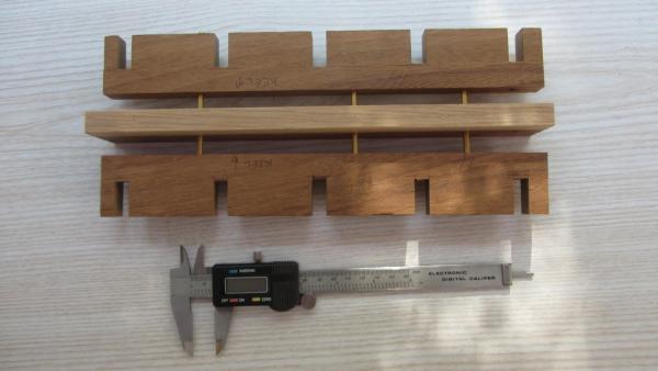
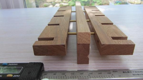
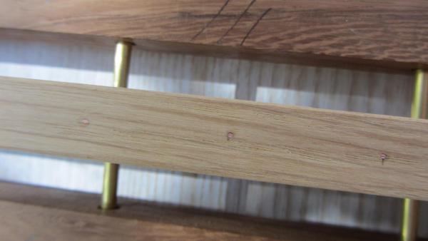
Hello. I have been asked to construct a Model to show the inside of a Ship. I have chosen to build the HMS Victory at a large scale of 1/36.90 Having got permission to use the plans from :- http://www.mountainhaven.com/VictoryXCP/PDFbin/Frame_Sta_( .pdf http://www.mountainhaven.com/VictoryXCP/PDFbin/Frame_Sta_0.pdf http://www.mountainhaven.com/VictoryXCP/PDFbin/Frame_Sta_3.pdf A previous topic regarding plans. http://modelshipworld.com/index.php?/topic/2885-large-scale-cross-section-drawings/#entry79890 I have redrawn the plans and added bits and made the drawings slightley more accurate. I am using adobe illustrator. The nice thing about using Illustrator is that it is vector drawn so it can be scaled up to any size. I am printing mine on A1 this gives me the scale of 1:36.90 The construction of this model will consist of five frames on each side. The Keel is make from mahogany. This will have holes for pining the frame guides. And the Garboard plank cutout. And false copper pins/rivets. The two frame guides are fixed to the keel. The frames are inserted into the frame guides and jig'ed to hold them at the correct shape and distance. I have also included the curvature of the hull into the model. The clamping blocks have a curve in to allow for the hull curvature. The clamping blocks will remain in place until I need to remove them for planking. The dummy frames will be added to the ends of the hull. I will use 4mm basswood for the dummy frames. Next I will plank the exterior. Then its building up the deck by deck. Orlop deck beams drawing. Orlop Deck LH.pdf Lower deck beams drawing. Lower Deck LH.pdf Middle deck beams drawing. Middle Deck LH.pdf Upper deck beams drawing. Upper Deck LH.pdf Quarter Deck beams drawings. Quarter Deck LH.pdf Section through centre drawings. hull.pdf Side view drawing. Hull Side View tmp.pdf Orlop deck layout. Orlop Deck Plan LH.pdf Lower Deck layout. Lower Deck Plan LHtemp.pdf Middle Deck layout. Middle Deck Plan LH.pdf Upper Deck layout. Upper Deck Plan LH.pdf Quarter Deck layout. Quarter Deck Plan LH.pdf Some of the timber preped for use. I will Add the drawings after I have as I compleated them. Started the build as you can see in the photos . Have now got to add the Dummey frames. Regards Antony.

- 209 replies
-
- 13
-
-
Hi Rich. Yes flickering LED's have been around for awhile. They are quite big and would look out of scale on some of our ships. The SMT led do not have flickering yet. SMT are 1mm to 2mm and very small. Regards Antony.
-
Hi . Yea wireing a LDR into the system is easy. Best one I have seen is a foil breeze switch. The slightest breeze makes the LED's flicker brighter and faster. Regards Antony.
-
Hi Brian. I like to develop things and I am a hobby programmer for the Arduino chip. That's as far as I want to go. That's why I shared this .. It's easy to construct very simple soldering. It gives six flickering led all with random timeings that use the Pulse Width Modulation to adjust the brightness. You can run two LED's from one PWM output which gives you twelve lights but two will be flickering at the same time. This can be adapted into the mega chip that gives 15 PWM outputs. Overkill on a model ship. Regards Antony.
-
Hi. Sorry for the late reply. not my video but it's the same Arduino with different programming. Regards Antony
-
Happy birthday Bob. Keeping the mind and body healthy is the key to a long and healthy life 74 today...You don't look a day over 50. Regards Antony.
-
Hi. A Futtocks is :- any of a number of timbers forming the lower, more curved portion of the frame in a wooden hull. Deadwood is the lower part of a ship's stem or stern. Should post this question here. .? Mabe in the General Discussion area. But if you have no idea what they are ... Where do you post Regards Antony .
-
Hi Grant. Love the rails. Never used ammonia before. Just hot water. Will give it ago next time I need to bend my timber into a tight curve. I love this Triton cross section forum as there are so many people with brillent ideas and so friendly. Regards Antony.
-
Hello Paddy. Looking very nice. The Garboard on the full size ship would also have been a large chunk to fit. With the two angles fitting into the keel. Also the angle and the Garboard twisting as it follows the frames. It's also one of the special planks .. Hence having a name. Must have been a nightmare with the tools they had then. Regards Antony.
-
Hello Marius. You have made a splendid job of this cross section. With out major tooling to do fine work can be very time consuming and test your skills to the limits. Well done. You Have produced a first class model Regards Antony.
-
Hello Paddy. Nice work on the treenails. I also have done mine before installing the planks. Regards Antony.
-
Hello Bob. I followed your Triton build which was very interesting and will put a extra cushion on the chair for this build. Looking forward to your build.. Regards Antony.
-
Hi Spencer. Have a look here I know it's fibre optic But the lanterns are ver small. http://modelshipworld.com/index.php?/topic/3163-fiber-optic-lanterns-ca-1845-196/ Looks good to me. Regards Antony.
-
Hi Bob. I goto agree with Paddy and Pete. A very nice build and very clean. Regards Antony.
-
Hello Alexandru. A very nice build. An interesting hull shape and construction. I also like the timber you have chosen for this ship. Regards Antony.
-
DeAgostini's HMS Victory Cross-Section -1/72
AntonyUK replied to bentrider1a's topic in Wood ship model kits
Hi. It seams that you can get DeAgostinl's in the USA. http://www.model-space.com/us/ships/hms-victory/ BUT no cross section Pester them for the cross section. I am building one at this time. Nice kit There are no plans with the build But the mags show you everything you need. There is a online build http://forum.model-space.co.uk/default.aspx?g=topics&f=93 Regards Antony.