


mbp521
-
Posts
989 -
Joined
-
Last visited
Content Type
Profiles
Forums
Gallery
Events
Posts posted by mbp521
-
-
Looking good John. If I recall (I'd have to go back and look at my build) I put a very thin piece of veneer over the stern to cover up the ends of the hull planks. After sanding and filling you cannot even tell it's there and hides the planking quite nicely.
For the filler, I have never used powdered filler before, but it looks like I may have to try it next time.
-Brian
-
Eberhard,
Sorry to hear the virus has caught up with you and hopefully you and your wife will fully recover soon, Good to see that it hasn't had any effect on your micro-modelling skills.
-Brian
- FriedClams, mtaylor and Keith Black
-
 3
3
-
The details on these steps alone are jaw dropping! Lots of tiny bits to contribute to the floor gods. Hold on to them carefully. 😁
-Brian
- KeithAug, mtaylor and Keith Black
-
3
-
1 hour ago, Cathead said:
Brian, yes, pilots and captains were totally different. River pilots were licensed independently (they, along with the chief engineer, were the only crewmembers required by law to have any training or licensure) and had to complete rigorous apprenticeships to ensure they knew the rivers they would be piloting on. They were roughly equivalent to harbor pilots, but much more powerful since they controlled the entire voyage, not just entry to/from a harbor. Most boats carried two pilots so there could always be one on duty. Captains did not have the authority to overrrule pilots in any matter of navigation or operational matters. Captains essentially oversaw the business management of the boat and would naturally set the intended schedule/destinations, but the actual act of getting there was out of their hands.
Pilots also operated independently and were not tied to a specific boat in any way (unless they signed a contract). They took jobs as they saw fit. Because of this, competent pilots were a prized commodity and could often extract exorbitant fees from captains (boats could not legally or practically operate without pilots). There are lots of stories of pilots playing desperate captains off one another for higher trip rates or other concessions.
Eric, thank you for the very useful information. This opens up a whole lot of questions and discussions. I am now curious as to what these gunboat pilots would have been paid given that they were prime targets for enemy snipers. This was one of the reasons for the port flap modifications to the pilot house on the Cairo. Snipers were picking the pilots off though the original port openings, which were roughly 12"x12". Iron flaps were fashioned to cover the ports during patrols in hostile waters. The pilots view was diminished considerably since now they were only able to peer through a hole in the flaps roughly the size of a half dollar. Talk about having to know the waters you were in.
Other thoughts that come to mind on this are, where did the pilots loyalties lay? Would they pilot boats for whatever side paid the most, or whichever side they felt has the best cause? Also, given that they were working for the military, were they conscripted into service and fall under the command of the ships captain? I'm not sure of how much military strategy these pilots had, so some direction would have to had been under the Captains orders in times of battle. And don't get me started on the Rams. What experienced riverboat pilot would purposefully want to drive his boat into another. I'm sure this goes against all of their training and natural instincts to dodge oncoming craft. I can just hear the first pilot that was ordered to ram another vessel. "You want me to do WHAT!" 😁
Looks like I have some more research to do.
-Brian
-
2 hours ago, Roger Pellett said:
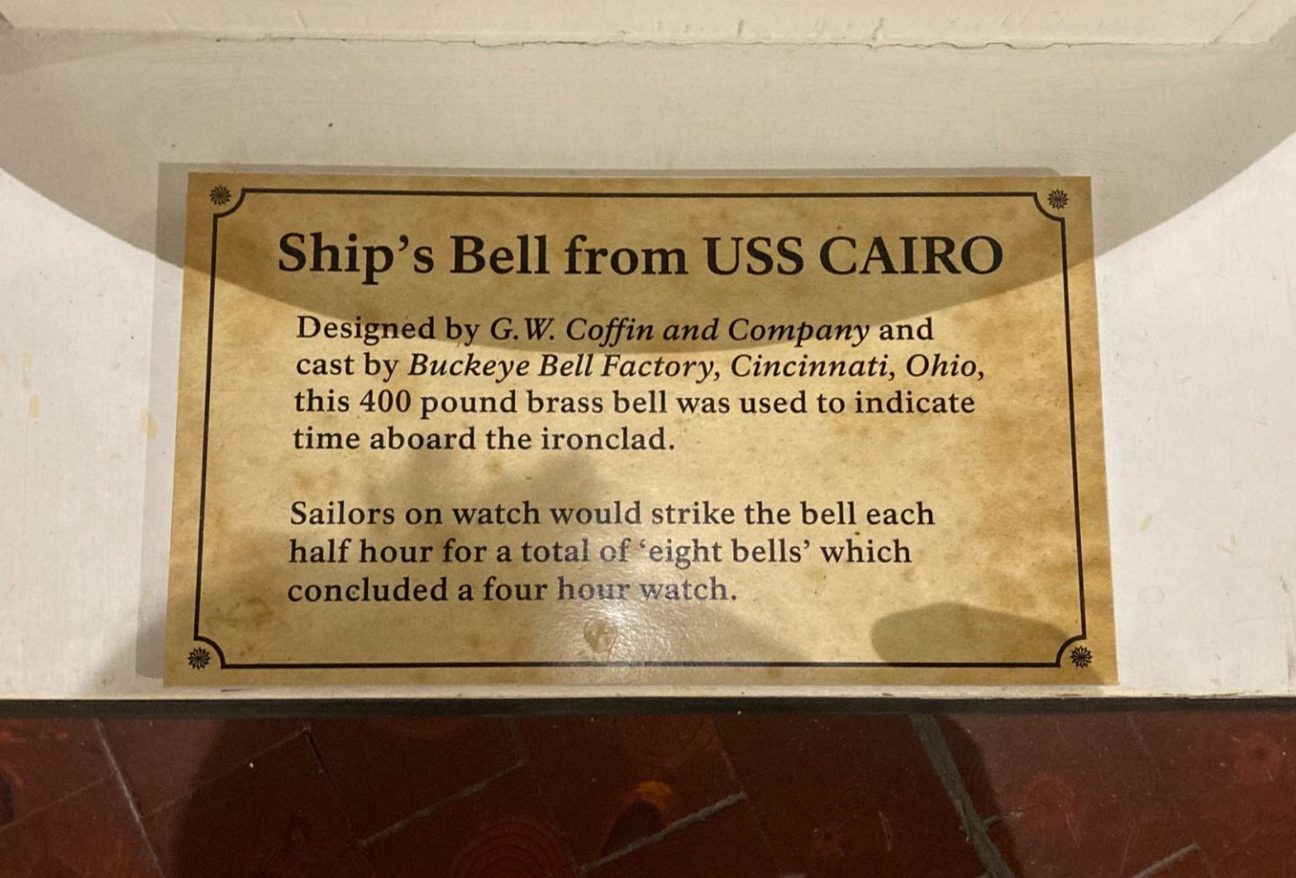
So what were these bells used for on the gunboats? By tilting the bell it would seem difficult to accurately toll the half hours of the watch cycle. Maybe a rope from the clapper to the Pilot house? A fog signal?
Roger, I am thinking that your second paragraph is correct. The plaque on the bell in the Cairo Museum states the same information.
2 hours ago, Roger Pellett said:Naval bells were different. They were hung from a fixed bracket and struck by pulling on a rope tied to the clapper. This allowed the precise time keeping during the four hour watch cycle. Ding ding- ding ding, etc.
The only difference being that this bell was mounted to a bracket with a pivot. However, where it was mounted was pretty tight quarters so I would assume that the pivot feature was not used and that there was a rope tied to the clapper that was rung every half hour by the watch. Funny thing is, I am not sure that these bells were originally for these gunboats. I can't remember where I read it, but I do recall seeing something about the bells being requisitioned from somewhere when the boats were completed. Generally Naval boats have the names of the ship cast on the bells (please correct me if I am wrong about this statement) but the bell on the Cairo just had the name of the foundry, date and the manufacturing company. Also, the bell was cast in 1860, a tad bit before the ACW, so that kind of confirms that they bell was not initially intended for the gunboats. I'm going to keep researching a bit more on this, but if I run into a dead end, I think I'll just mount the bell on a pedestal, maybe incorporate it into a flag locker or something and install a rope on the clapper.
-Brian
- Keith Black, KeithAug, Cathead and 4 others
-
7
-
35 minutes ago, Cathead said:
Brian, my apologies, I completely and shamefully misinterpreted and misused terminology. Never mind.
No apology needed. It is typical of the military to take a normal term and make it their own by giving it a totally new definition. 😁 If they can’t come up with a new definition they’ll just give an acronym to confuse the civilian population. I definitely know this from experience.
37 minutes ago, Cathead said:The way you describe it, though, the use of pilots on these naval vessels sounds exactly the same as normal river practice, where the pilot was the de facto captain of the vessel, while the "real" captain was more of a business manager and had no say or authority over navigation.
I had no idea of this fact. I always thought that the riverboat captains and the pilots were one and the same. It totally makes sense though. You would want someone competent steering the boat while the Captain schmoozes with the passengers.
-Brian
- mtaylor, Canute and Keith Black
-
3
-
1 hour ago, BANYAN said:
Absolutely wonderful detail Brian; Cairo is really brought to life with all your added detail. No wonder you attracted your unwanted visitor, it simply heard about your build and came to have a look for itself
")
Thank you Pat for the kind words. The added little details to me are one of my favorite things to build. They really start to pull things together and add that touch of realism to the model. As for my little visitor, next time he can just peek in the window if he wants to take a look. I'll be more than happy to show it to him with a couple of panes of glass between us. 😁
-Brian
- Keith Black, mtaylor and Canute
-
3
-
1 hour ago, Cathead said:
Awesome! Also, I love snakes, and would happily have hand-caught and carried that fellow out for you.
One thought on the bell location in front of vs. atop the wheel house: in most regular steamboats I've seen, the bell was located in front of the wheelhouse on the hurricane deck. I assume this is not only because, as you said, the wheelhouse would have been too flimsy, but also because it makes running a pull rope from the wheelhouse out to the bell easy: it goes out the front, not up through the roof. This detail can be seen on many historic photos. Finally, and this thought just occurred to me, having a large bell tolling right over the pilot's head might have deafened him; better to have it out further in front?
Eric, I would have been more than willing to let you haul him off. To me, something that slithers across the ground without legs is just unnatural. When I am out walking the property, I am always carrying, just on the off chance that I run into a snake (or something worse). We have an over abundance of Copperheads, Water Moccasins, and Rattlers out here and I am not going to take the time or get close enough to check whether or not is is venomous. Shoot first, look later 😁. I don't deliberately go out in search of them, they have just as much right to be out there as I do. But if one is in my path or where I'm working (i.e. the chicken coop, barns, etc...), then it's toast.
As for the bell placement on the Ironclads, the "wheelhouse" in the case of these boats is the structure that covers the paddlewheel. The "pilothouse" refers to the where the ships wheel is up front. Since patrolling the Western Rivers was somewhat new territory for the U.S. military, the Brown Water Navy hired civilian pilots who were very familiar with the waterways to pilot these boats. My guess is this is why they called it the "Pilot House". A little bit different than a standard riverboat and it took me a bit to get used to the terminology differences.
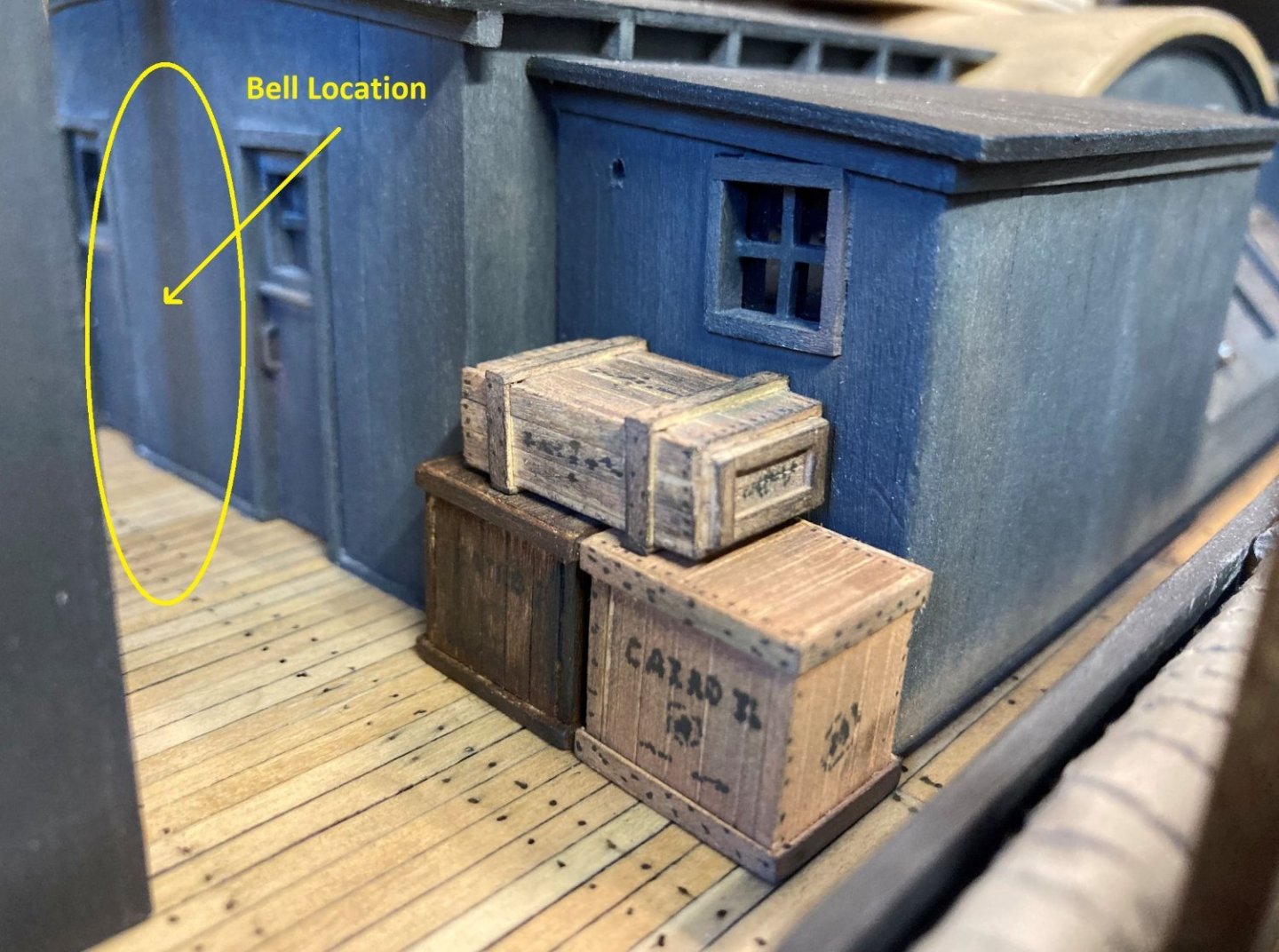
According to the divers that salvaged the Cairo, on one of their dives, they slipped down over the forward wall of the structure and found the bell. Unfortunately they didn't mention anything about whether it was mounted on a pedestal or not, so I am not sure how to place it. This bell was used to keep time on crew watches, and would be tolled once every half hour, so it seems to me that it would have been too low to the deck to ring if it wasn't mounted a little higher up. I'm still looking into it though.
The bell was located in this area.
-Brian
- Cathead, FriedClams, KeithAug and 4 others
-
7
-
1 hour ago, KeithAug said:
Well that was an extensive and excellent update Brian. Why did you decide not to use brass for the ships bell - not withstanding the question the bell looks excellent.
Thank you Keith, I look at your Germania build and the metal work that you have done on that, and think to myself, maybe one day in about 100 years I'll be able to do that. 😁
Actually I would love to have done the bell out of brass as I did my cannons, it's just at this time I don't have the equipment or the skills (yet) to successfully make one that way, and I didn't want to pester the guy who made my cannons for something so small. A milling machine is on my list of tools to get one day, and would have definitely come in handy on this build for several parts, unfortunately the budget hasn't provided enough fundage for one yet. For now my little cheapo mini-lathe will have to work.
-Brian
- Keith Black, FriedClams, Canute and 1 other
-
4
-
Hello again everyone,
Time for another update on the Cairo build.
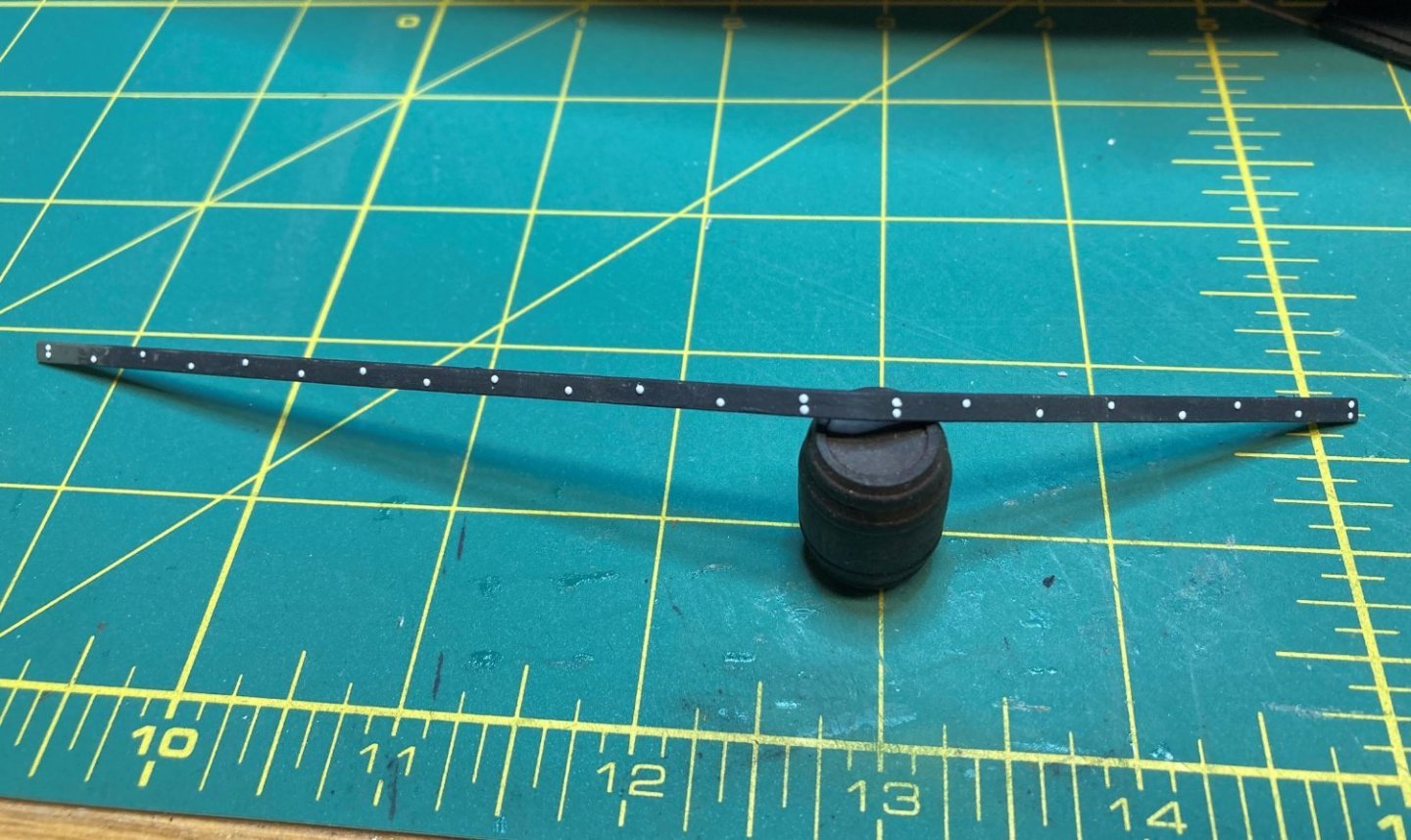
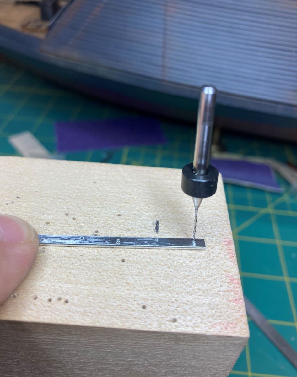
Picking up where I left off last time, I started work on the bow guard. I made this from a strip of flexible aluminum, the same material that I made the paddlewheel from. I drilled holes in alternating sides matching the original.

Then the strip was bent to match the contour of the bow. I was not able to determine the length of how far this guard ran back along the center keel, so I guesstimated it at about 18' which put it at approximately the length of the foredeck.
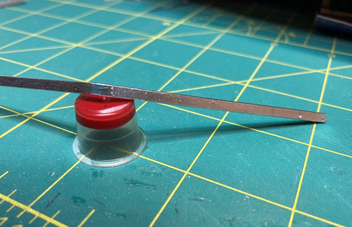
After it was drilled and bent I simulated the rivets in it, the same as I did for the iron casement plating. I left a couple of them empty to allow for me to drill into the keel and put some of the styrene rod into the wood. This will give it a better bond than just gluing it to the keel.
All that is left to do is paint it up and install it. I am holding off on installing it until later. Occasionally I pull the boat down off the bench and place the bow on the floor to work on it, so I don't want to mess up the paint on the guard.
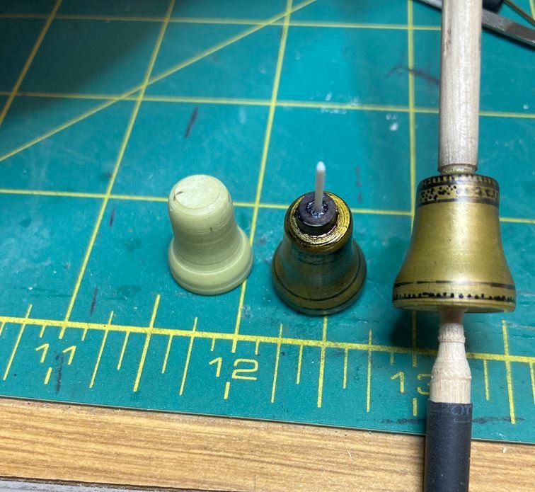
Next up was construction of the ships bell. The bell was made from Milliput that I turned on the lathe. My first version was going along great, but I didn't think the process through enough. I formed a rod out of the Milliput and chucked it in the lathe. By the time I got to forming the top of the bell, the Milliput was too thin and broke off the headstock before I could finish it.
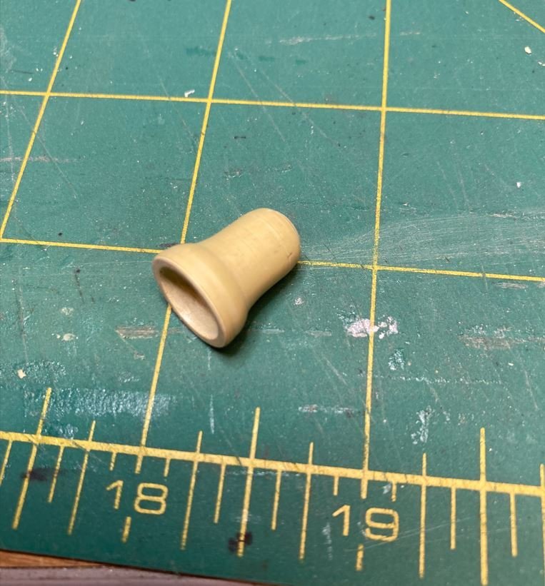
Round two, I formed the Milliput around a small dowel for reinforcement.
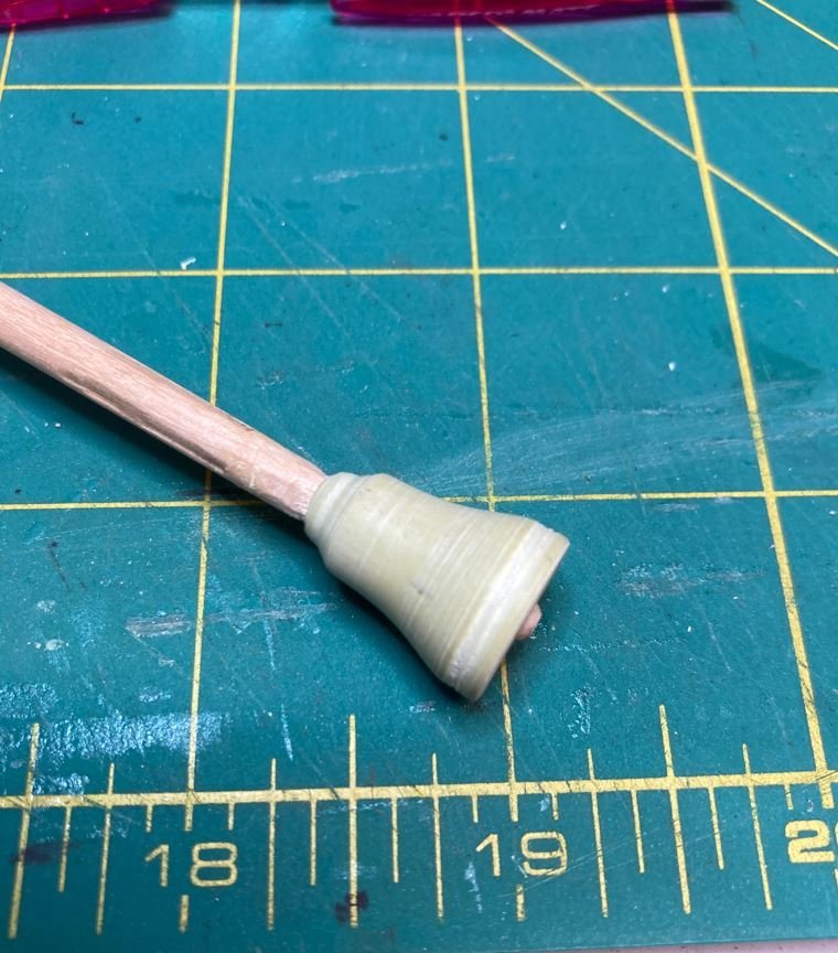
This one worked a lot better and I was able to get the bell shaped. However, after I got it painted up, I realized that the shape wasn't quite right and it was a tad bit too tall.
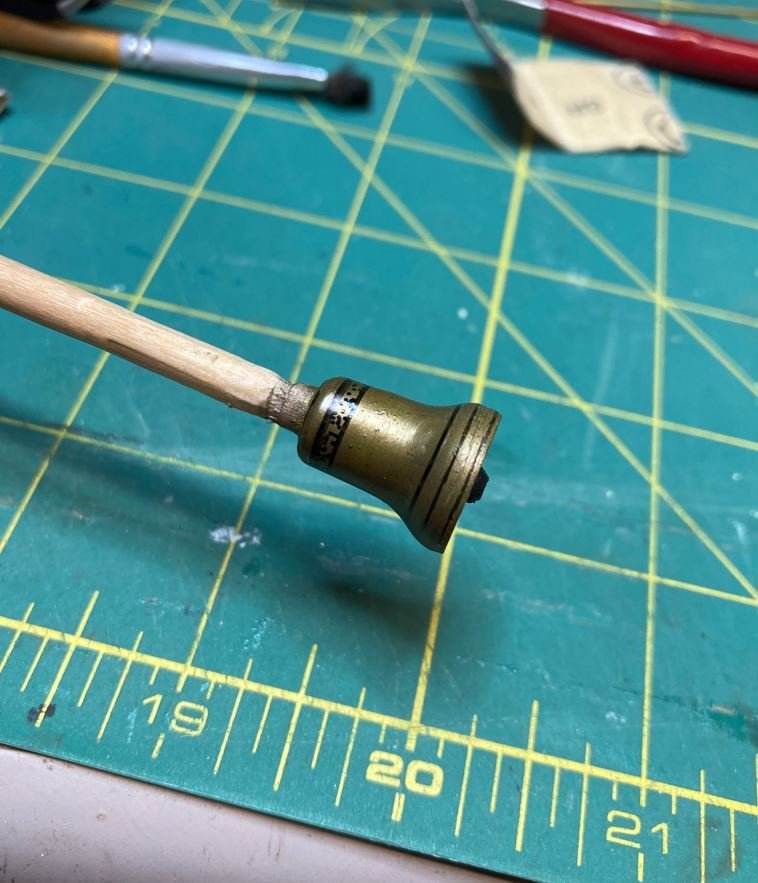
Round three. Turning again.
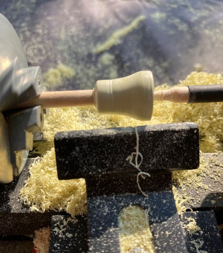
I think I got it right this time.
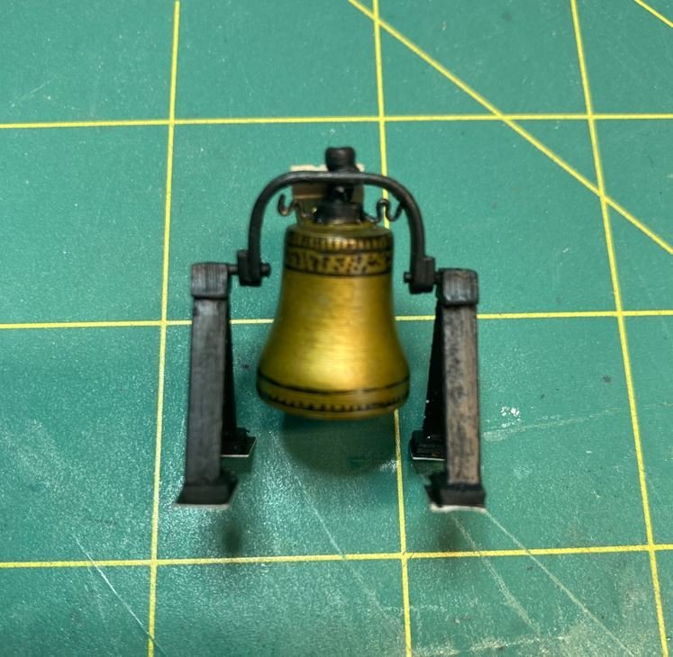
Build up of the frame and scrollwork,
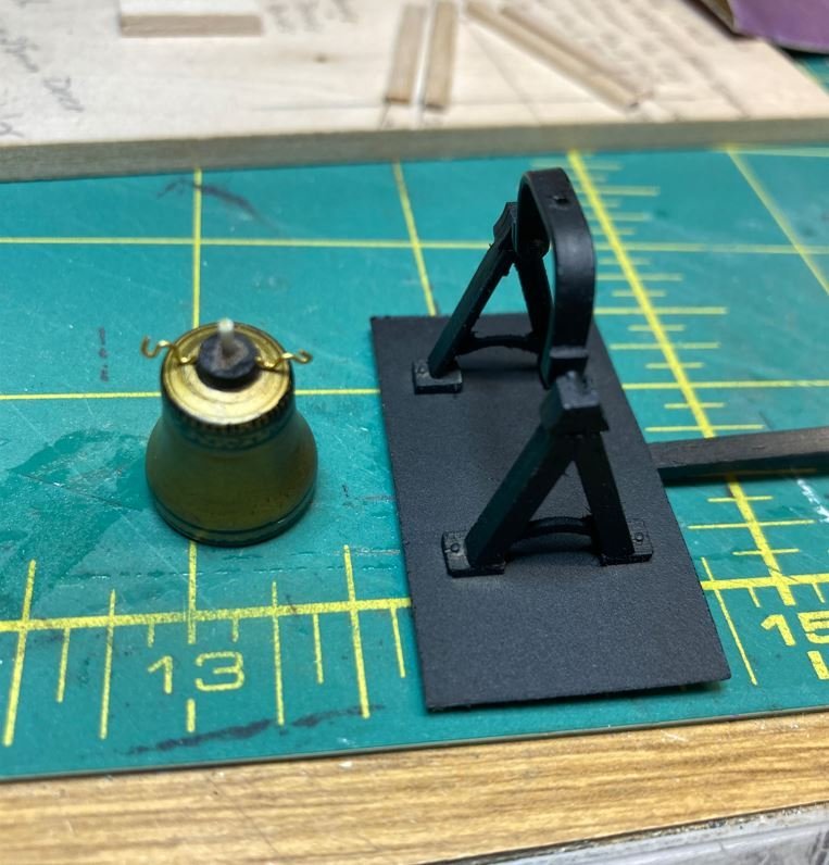
Mounted in the frame.
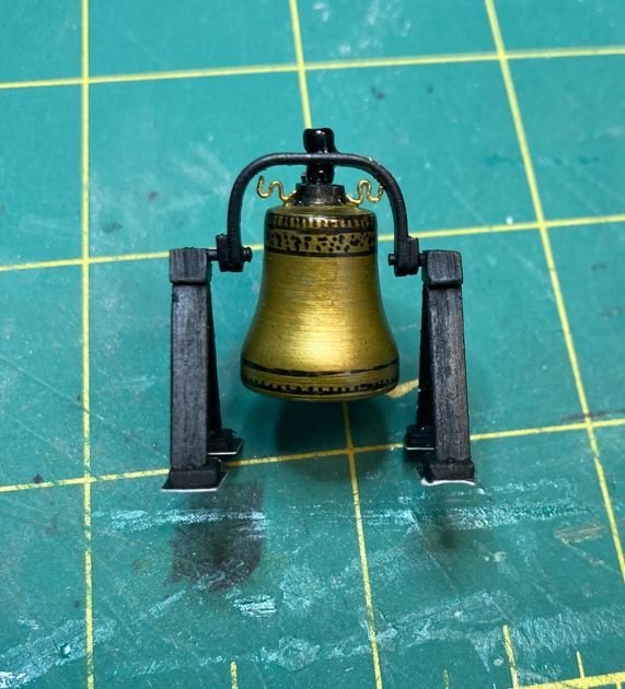
and all painted up.
During the salvage when divers discovered the bell, they placed it's location in front of the wheelhouse structure. I have seen a few models, including the one in the Cairo museum where the builder has it located on top of the wheelhouse structure. If this were correct, the scaling would be off if it were indeed located here. Given that the recovered bell assembly is roughly 48” tall, including the mount, and the clearance between the wheelhouse structure roof and the centerline beam is less than 36” it doesn’t seem to fit. The bell also weighing in at 400+ lbs., seems like a heavy object to set on top of the thin roof of the wheelhouse, so I am not sure these models are correct. I am going to go with the information provided from the divers in that it should be located in front of the structure, my only piece of missing information is, was it mounted on a pedestal, or directly on the deck? I'm still researching this, so the bell will sit in the drawer until I can come up with an answer.
Next it was on to the aft skylights. This is another item that is not shown on any of the plans or existing models, but contemporary pictures of the City Class boats show their existence. The picture of the Cairo does not give a clear indication of them, since the ships boats cover the area of where they are located, but several other photos of the other City Class boats clearly show them to be located just above the aft two cannons. So this is what I am going with since the Cairo, Cincinnati and Mound City were all constructed at the same shipyard in Mound City and contemporary photos of the Cincinnati, St. Louis and Mound City all clearly show the skylights in place, my Cairo is going to have them located there as well.
Location templates in place.
Frames built up and temp located.
I stared having a bit of an anxiety attack at this point, cutting holes in the deck again. During the cutting process, I forgot to take pictures "again". There are some pictures of other completed items that will show the finished product, and I'll point them out as I go. I still have to make the panels for them, which means that I will have to borrow the Admirals Cricut again. That will be on a future update.
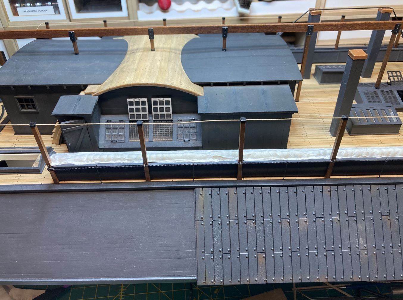
Then it was on to finishing up the Starboard hammock rack.
Next was the center beam that runs the length of the Hurricane Deck. I have still not been able to turn up any information on what the proper name for this beam, it seems to be pretty unique to the City Class boats. Its general purpose seems to be the center support for the canopies. On the bottom right of the next picture, you can see the completed and installed aft skylight frames.
Once the center beam was installed I started work on the rope stanchions that run along the outboard side of the hammock racks. I have been having trouble with my Brass Black retaining it's color. For some reason it tends to rub off with a lot of handling. So I tried a different method. I had some black plastic coated wire from a previous build that I took a torch to to melt the plastic off. When I heated the steel wire up to cherry red and cooled it in water, it left a perfect blackened patina on the wire that doesn't rub off.
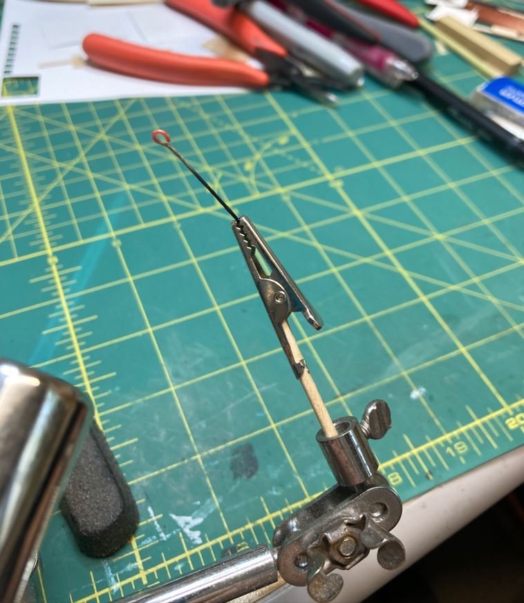
After heating and cooling.
Stanchions in place, Port side.
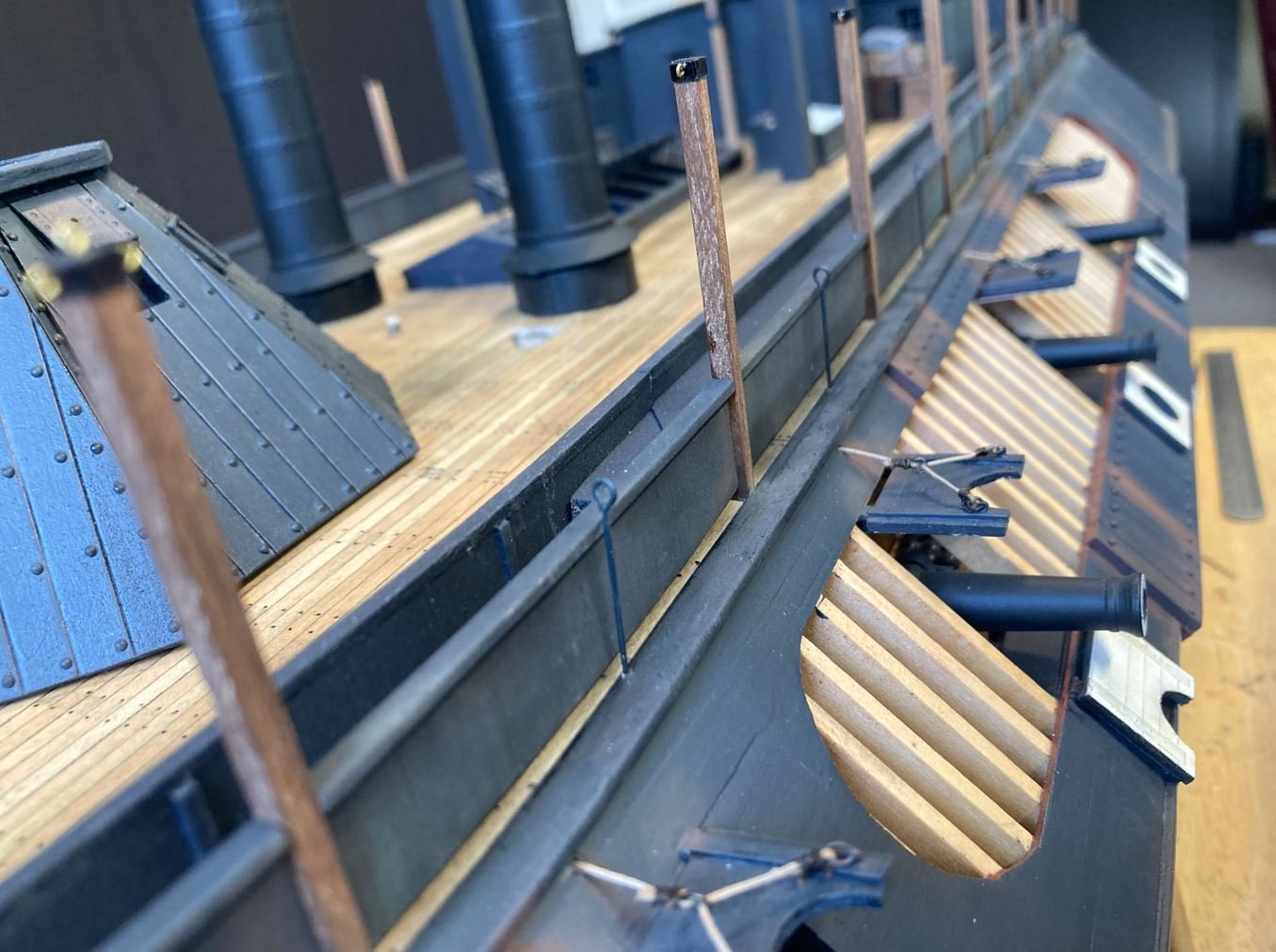
Stanchions and rope installed, Starboard side.
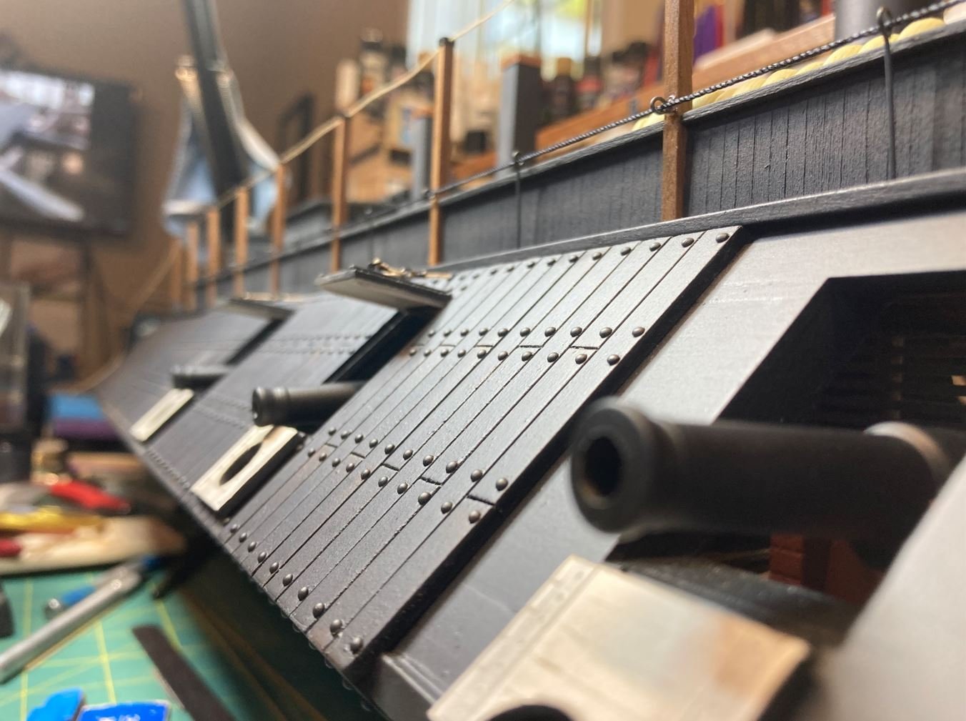
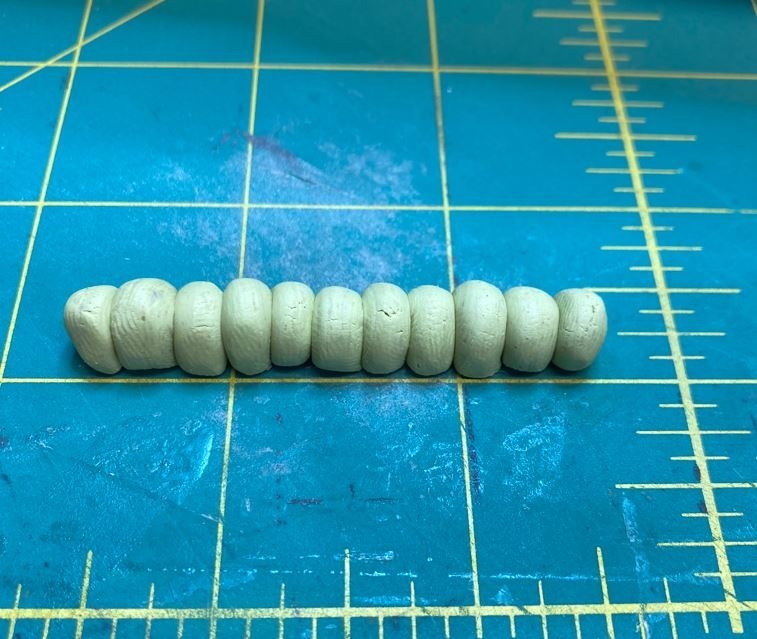
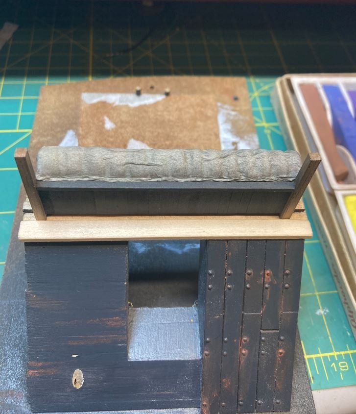
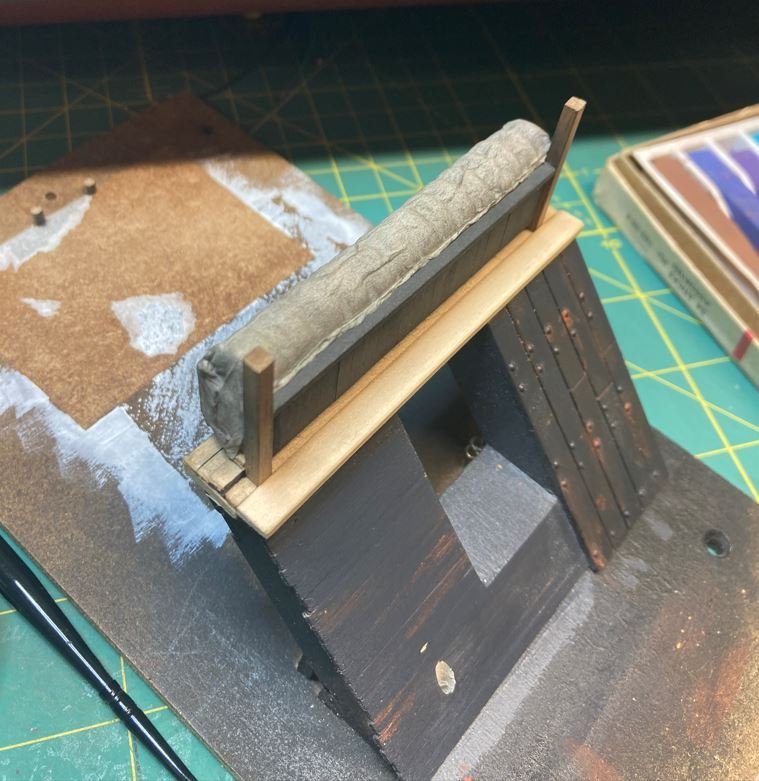
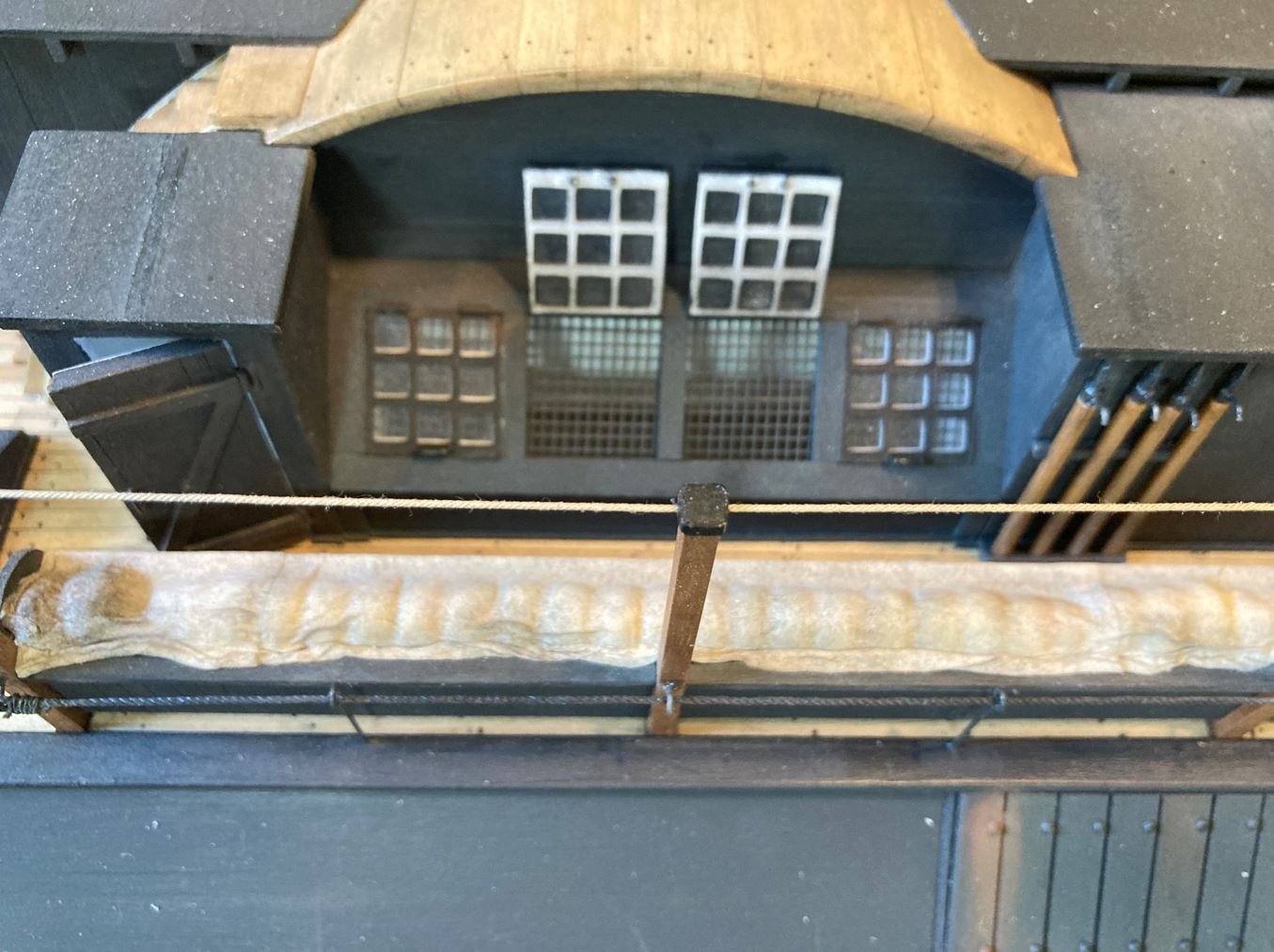
Now it was time to test a new skill. Simulating tarps. I have watched numerous YouTube videos on how to make a model tarp and properly weather it, making it look as realistic as possible. I made me up some simulated hammocks for my mockup out of Milliput.
I then placed them in the hammock rack, covered it with some tissue, soaked the tissue down with 50/50 clear Elmer's Glue and water, let that dry and then weathered it with some pastels.
My first attempt.
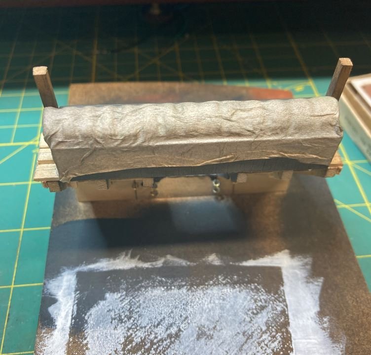
I was pretty pleased with the results, so it was on to the real thing. I liked the way the Milliput looked under the tarp on my mockup, so I made up 150 more of them.
I loaded up the Starboard side racks.
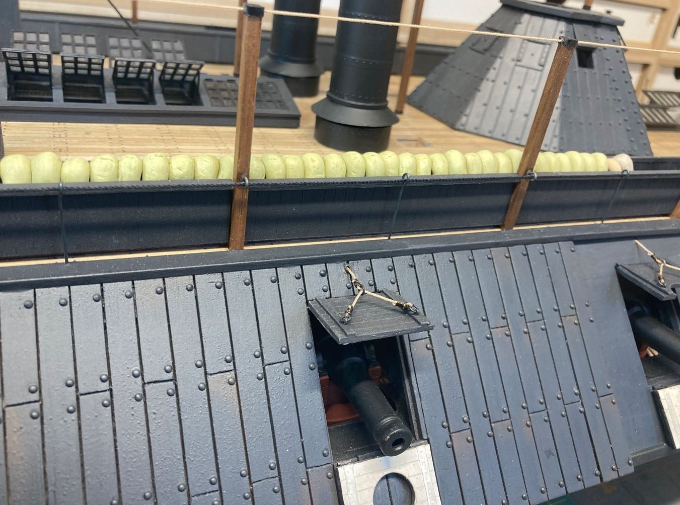
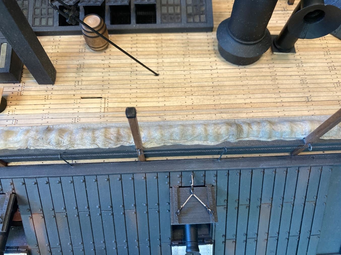
and started covering them with the tissue.
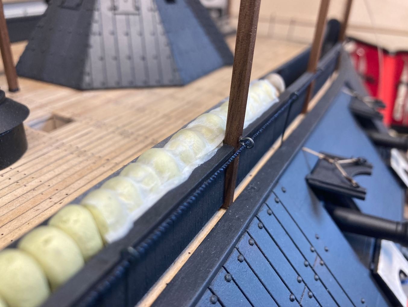
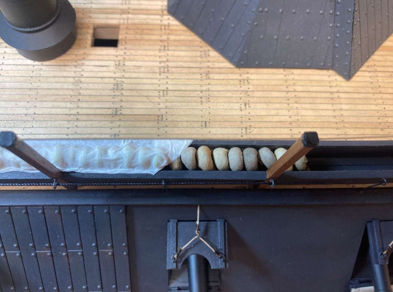
All of the tissue in place and dry. Now for the weathering. First few coats of weathering on. I am having trouble getting the lighting right on these pictures. For some reason they are not picking up all of the colors and tend to look a little light. I am going to play around with taking pictures at different times of the day to see if I can get better results. They actually look pretty good in real life, just not in the pictures. I do welcome any comments or tips on how to improve the look.
While I was working on the weathering. I heard a weird noise coming from under my work bench. I couldn't for the life of me figure out what it was so I started looking around and moving some of the junk I have stored under there.
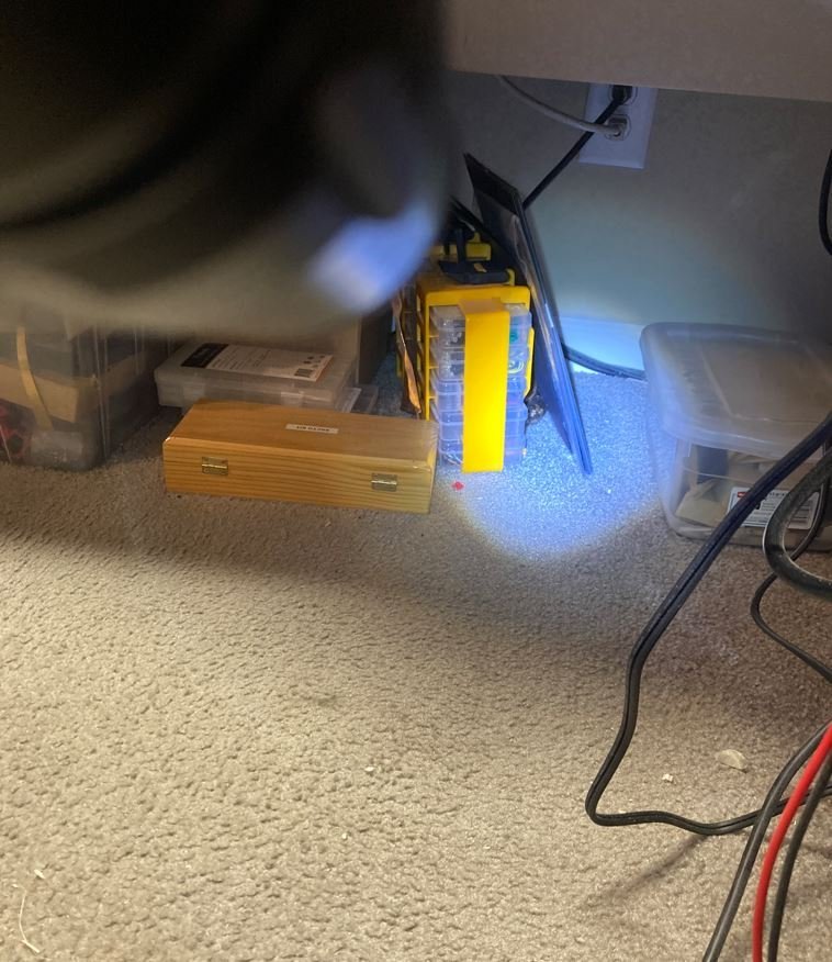
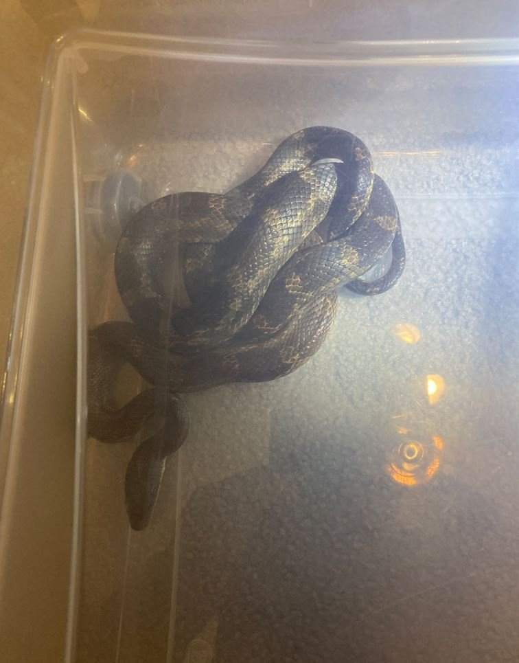
That was when I found a very unwanted visitor. Somehow or another this three foot rat snake found it's way into my house and made his way into my shipyard/spare bedroom. Needless to say the Admiral, along with myself were pretty freaked out. Two critters I hate most in life are snakes and spider, and to find one inches from my feet, well I didn't get much sleep that night. My first thought was to shoot it, but I really didn't want to put a hole in my floor, not to mention deafening myself discharging a firearm in the house, so I trapped it in a storage tub and set the little fellow free in the back pasture. I'm sure all he was trying to do was escape the Texas heat and soak up some of my AC. Sorry pal, not in my house. 😁
After recuperating from the slithery house guest, it was back to work.
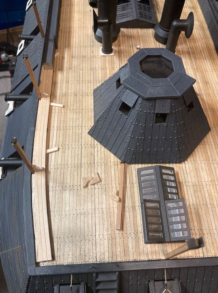
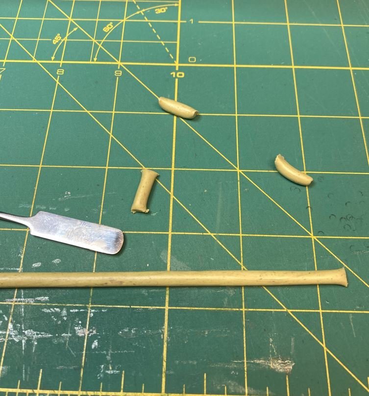
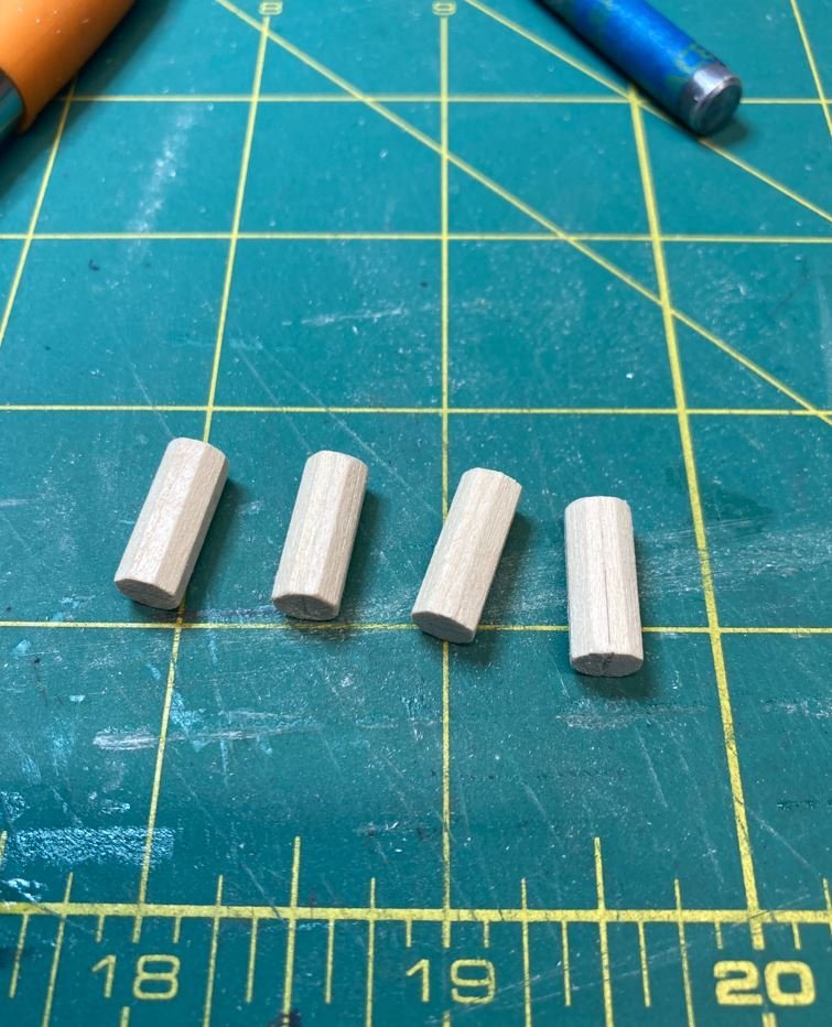
I turned my focus to the elm tree pumps used to remove water from the forward and aft holds. The City Class boats had three of these. One located on the forward deck and two mounted on the fantail, one over each pontoon forming the aft hull. None of these survived the salvage, not sure if they were lost during the recovery efforts or they just rotted away over time, but the holes where they were placed in were visible on the deck when the ship was raised and there is documentation of three octagonal holes that fit the profile of this style of pump. So I researched several pictures of these pumps and found a good version of what they could have looked like on other period ships, and modeled mine after those pictures.
I started off by turning a dowel into an octagon, to for the shape of the pump housing.
Then I cut them down to size, making an extra one, "just in case".
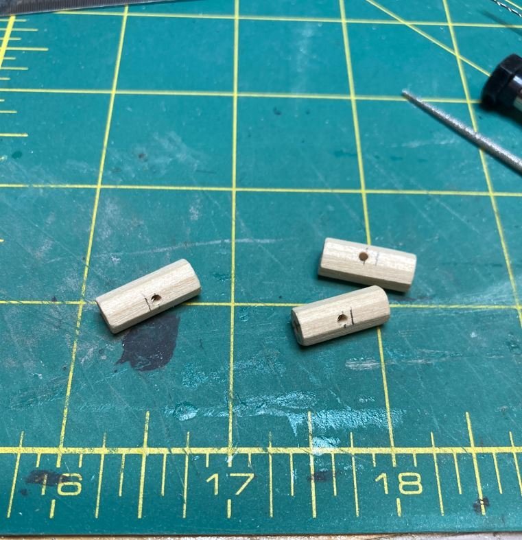
Holes for the outflow pipe and the core drilled out.
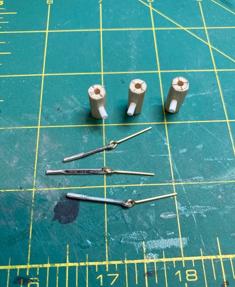
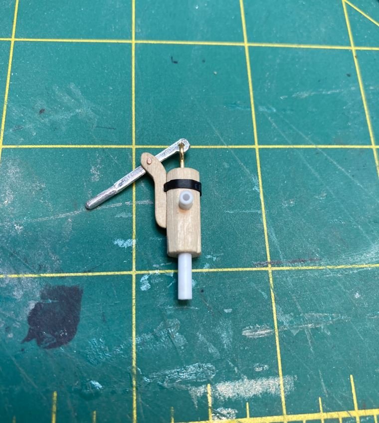
Outflow pipes installed and handles made.
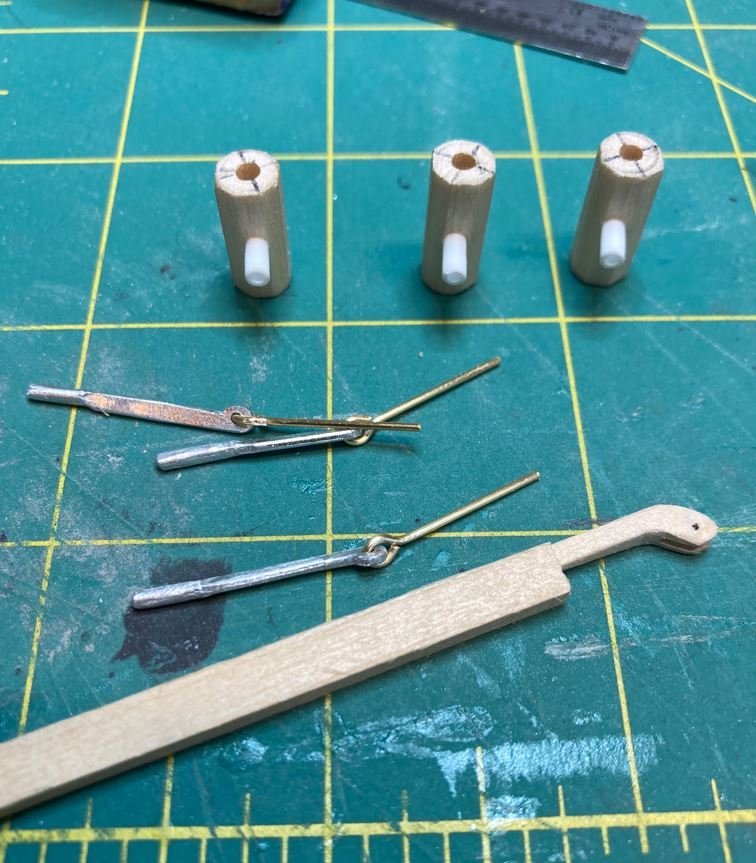
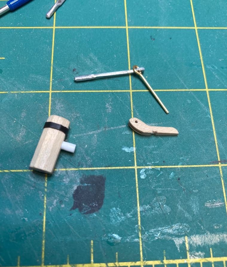
Completed assembly.
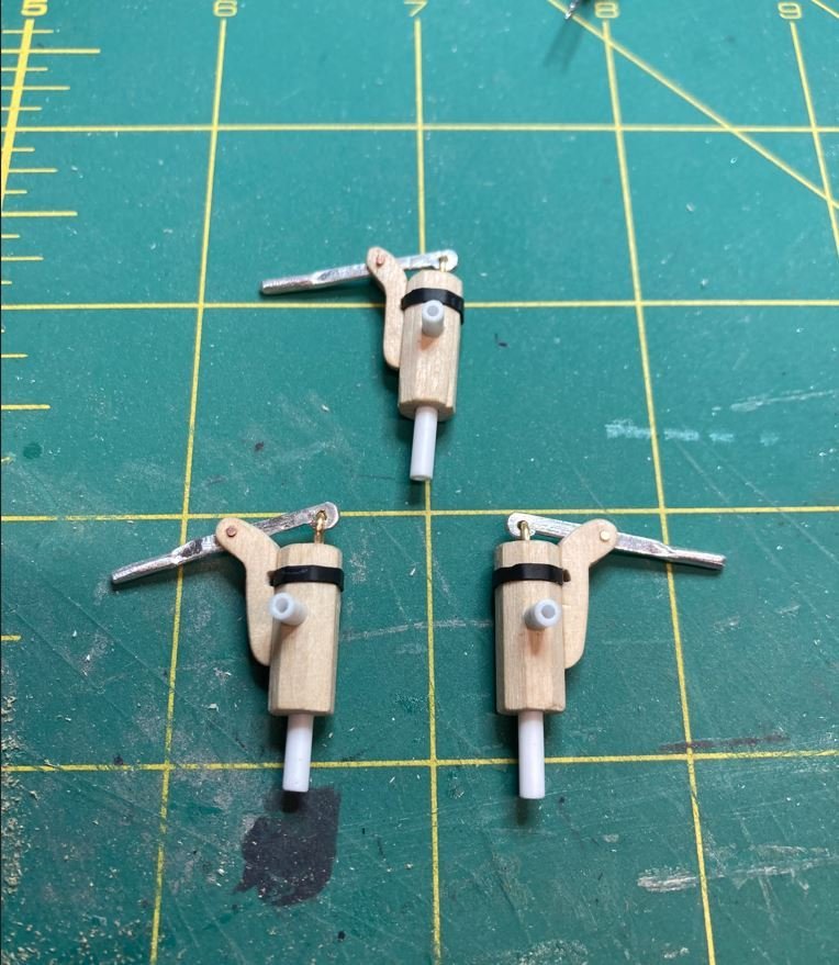
All three completed. Just needs paint.
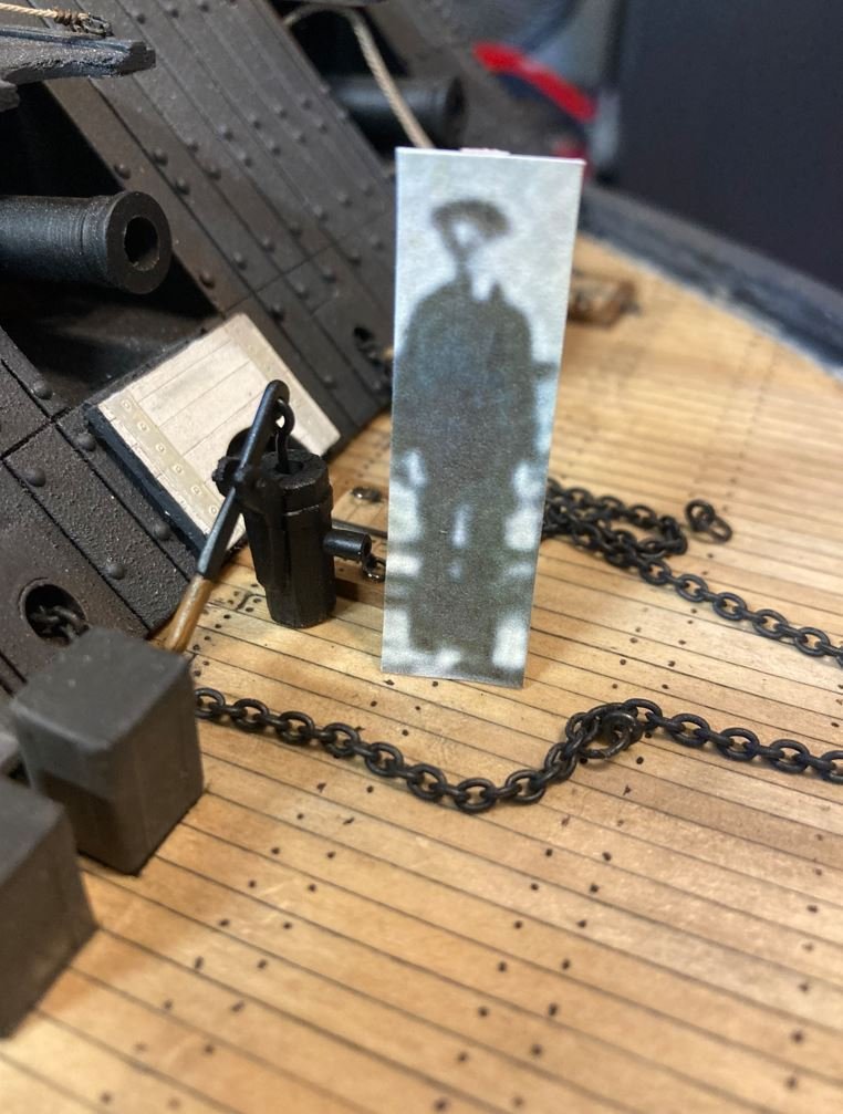
Forward pump installed with my crewmember standup for reference.
Aft Starboard pump installed.
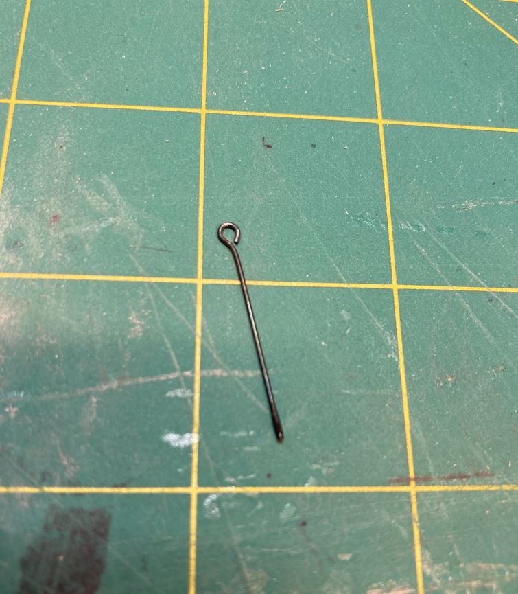
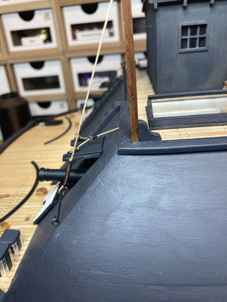
Along the tops of the stanchions on the Port and Starboard sides there is a rope that runs from the stern to the second stanchion. This looks to serve as an anchor point for the canopy ropes as well as some support for the stanchions themselves. I went ahead and installed this as well. I completed the aft anchor, but left the forward side undone until I finish all the work on the Hurricane Deck. I wanted to be able to remove it if it got in the way. The eyebolt sticking through is for the rope handrails that run along the backside/frontside to keep crewmembers from falling down the casements. I had just not trimmed it off when I snapped this shot.
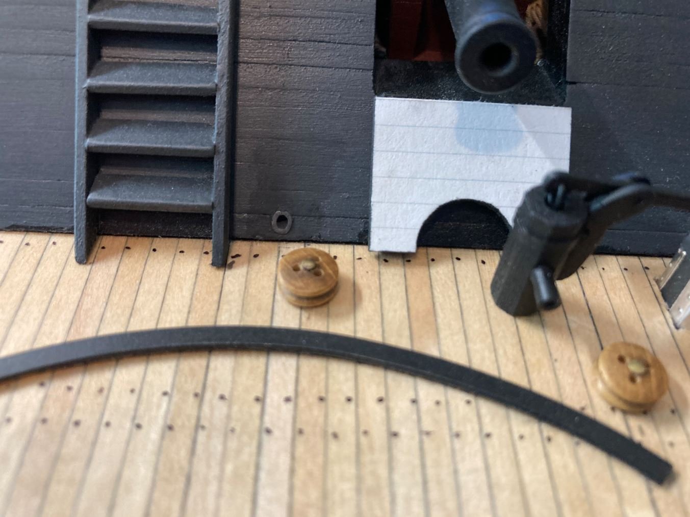
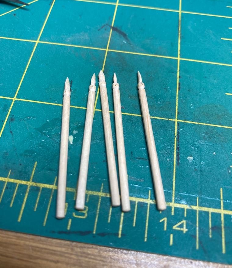
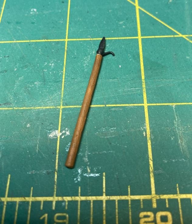
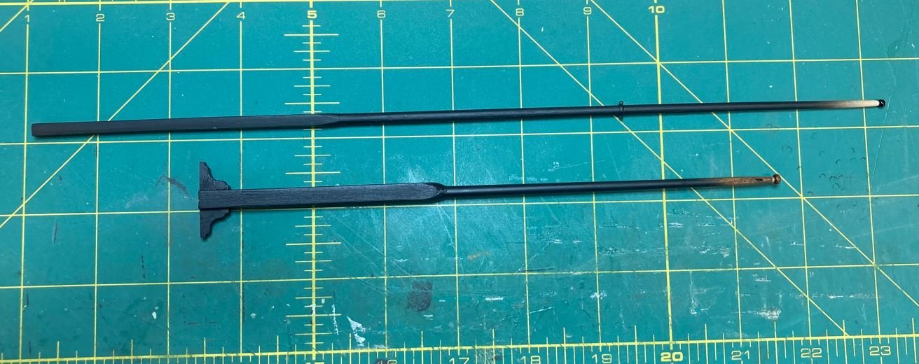
More deck features that I worked on were adding some boat hooks/boarding pikes. I couldn't find any pictures of these, and there are none on display in the museum, but there is mention of one of the divers coming up with one during the salvage, so I figured I would add those as well. I just carved these out of some decorative toothpicks.
Added a hook.
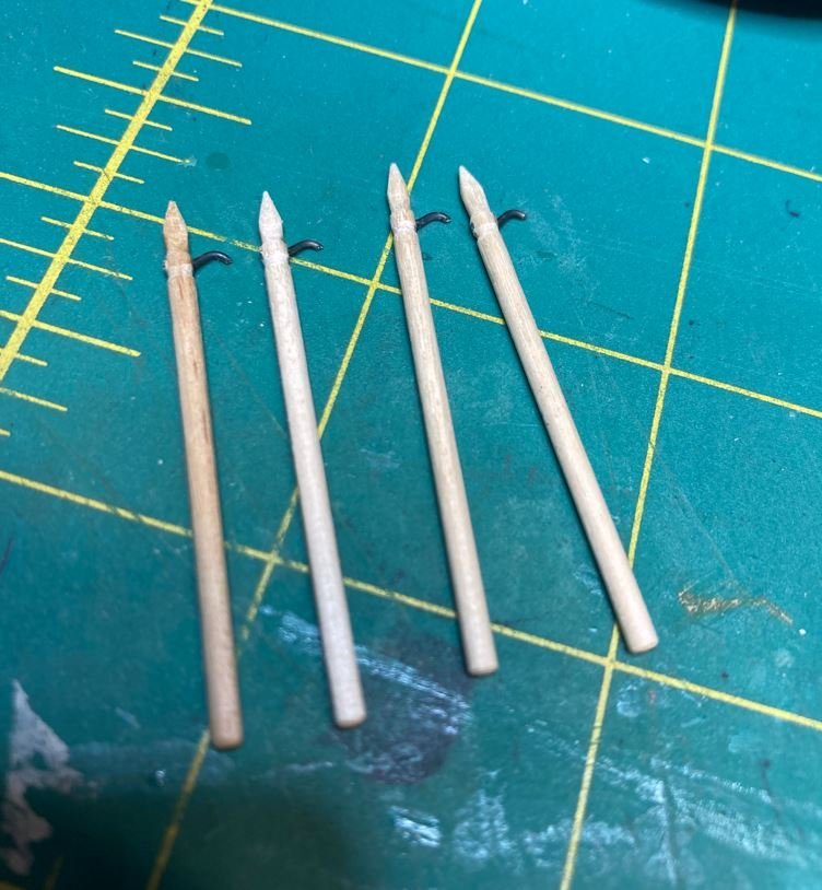
Painted them up.
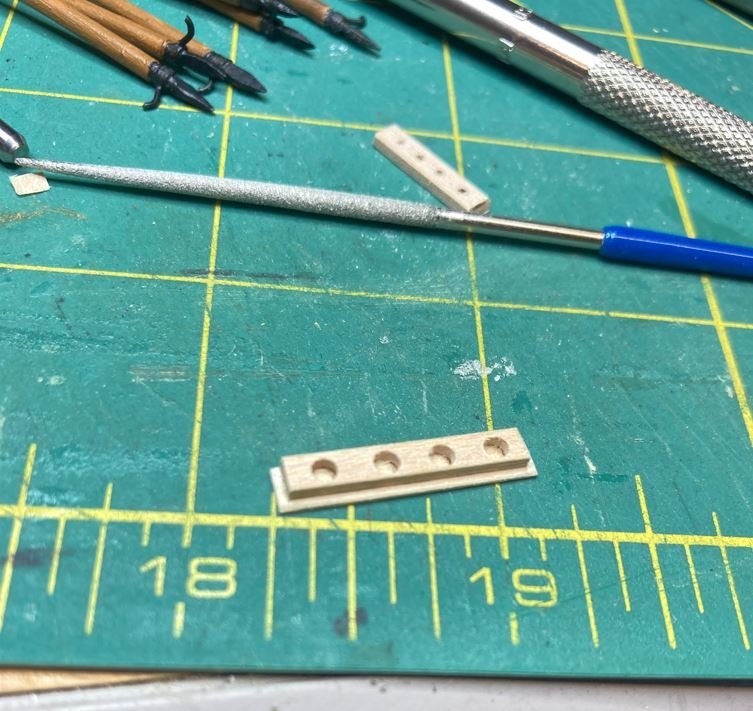
Made a rack for them to stand in.
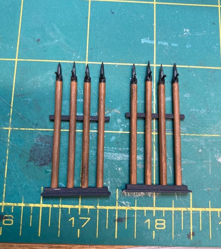
And installed there in a location that seem like it would be the most useful. Along the wall of the wheelhouse structure, by the ships boats.
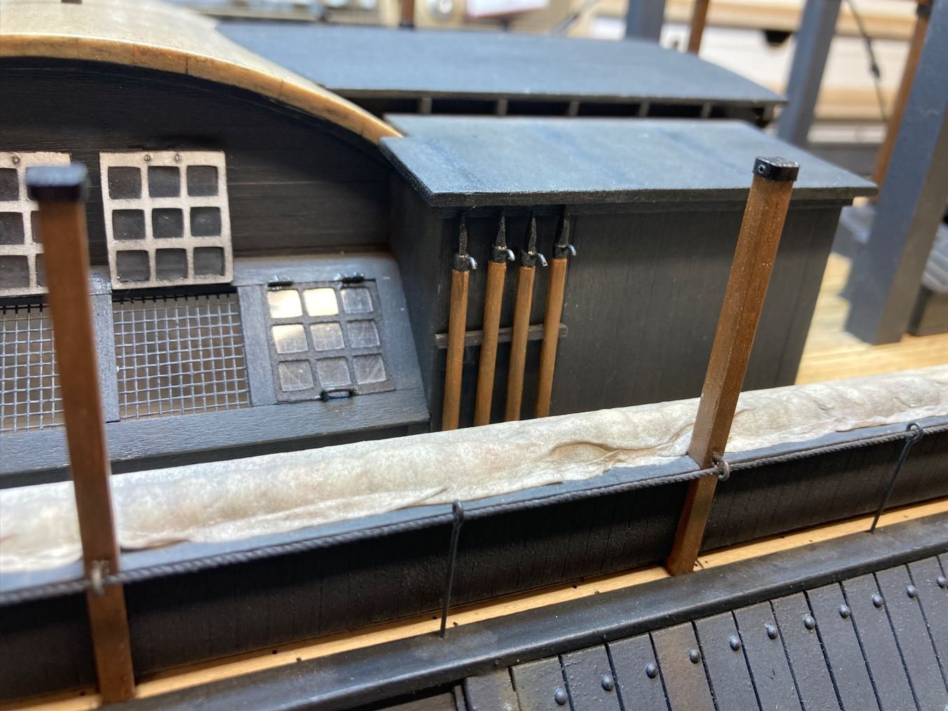
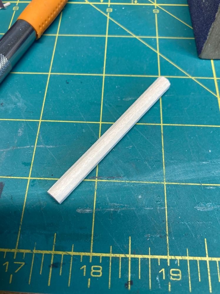
I also made up a couple of the masts. These won't be installed until later, I was just looking for something easy to build up. I still need to make up one more of the shorter ones and finish painting these.
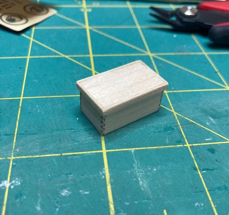
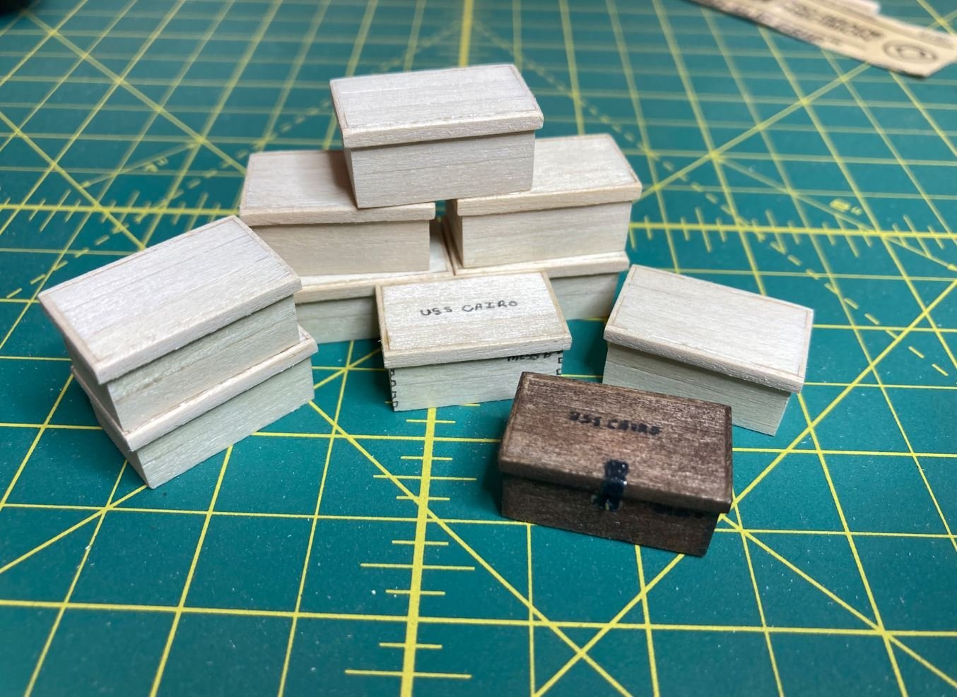
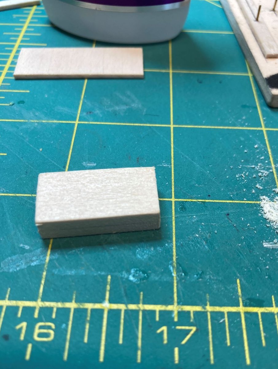
Finally I started building up some of the crews mess kits. I just laminated a pine block with thin basswood strips, to simulated the planks, added some trim for the top and weathered them up.
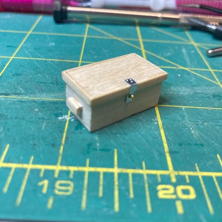
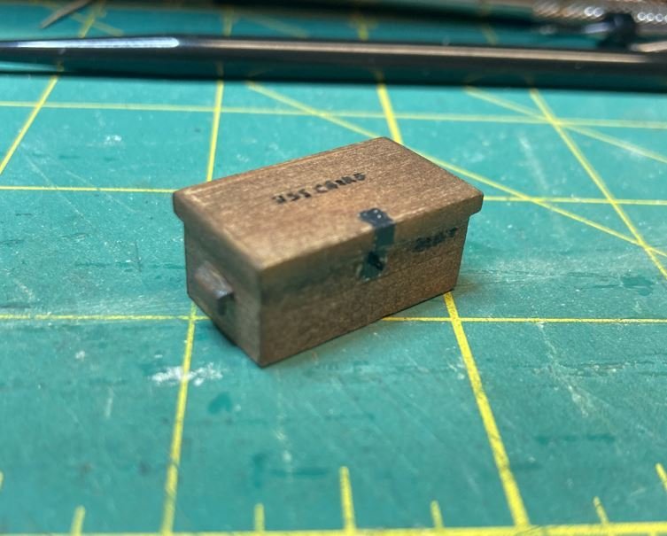
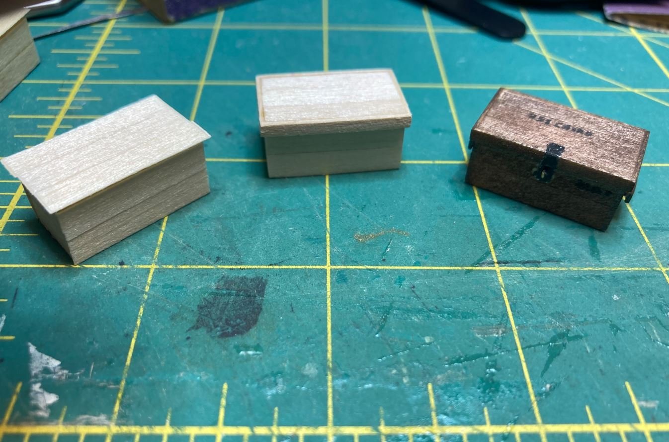
One complete, nine more to go. I need to figure out how to make up tiny padlocks to go on them. Not sure of how I am going todo that, I'll just have to do what I can and see if I can get it right.
One last thing. 1-2-3 blocks are heavy. If you use them, please don't drop them on you model. 😪 Thankfully it didn't dent the cannon, only chipped the paint. Some minor repairs that I will have to take care of.
And finally, one last shot of how she is sitting today. I'm getting there. I might just be able to get her completed by the 160th anniversary of her sinking coming up this December.
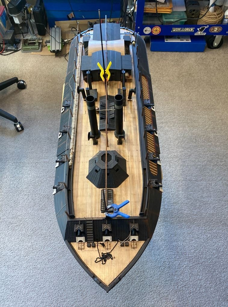
Thank you all for stopping by and having a look. As always, I appreciate the likes, comments and kind words.
-Brian
-
Keith,
So glad you made it through the rough patch and were able to close that chapter. God has a plan for us all, and he doesn’t task us with anything that he doesn’t feel we can t handle.
Funny, I was just going to through some of my old junk the other day and saying to myself why in the world was I keeping this. One example of the useless stuff that I had was an old receipt from Model Expo back in 1984 for a model purchase. Not sure why I was hanging on to it, but I had it.
The Madawaska tag will be an excellent addition to the build, and glad the seller was willing to negotiate. I’ve had several instances of Ebay auctions where the seller had OBO on it, but wouldn’t budge on the price. Seriously what’s the point in putting OBO if you aren’t willing to work on the price? Hopefully this one didn’t take too much of a bite out of the budget.
Stay strong my friend, we got your back if you need anything.
-Brian
-
I’m having trouble distinguishing between the model and the real launch. Amazing!
-Brian
- KeithAug, mtaylor and Keith Black
-
3
-
Keith,
My apologies for being way late to the party on this. I just spent the last couple of days going through all 63 pages of this magnificent build. Man have I been missing out! What a beautiful model you have going on here.
You are definitely a master of your craft and I feel so insignificant now.
 I know I am jumping late, but I'm definitely on for the remainder of the journey.
-Brian
- mtaylor, Keith Black and KeithAug
-
3
-
Slow is good. We are a patient group, and it just means you are taking your time on a quality build. Beautiful job so far!
As for the bottom planks being lined up, a good sanding and a few coats of paint should cover it nicely. And if you are going to mount it directly to the base, they’ll never be seen.
-Brian -
John,
Glad to see you back at it. Nice job so far on the hull planking.
You are correct, you can never have enough clamps in this hobby.
-Brian
-
Hello again everyone,
I have returned with another update. This time around it is not so much the progress made, but reworking areas that I found I built in error after more research and discussion.
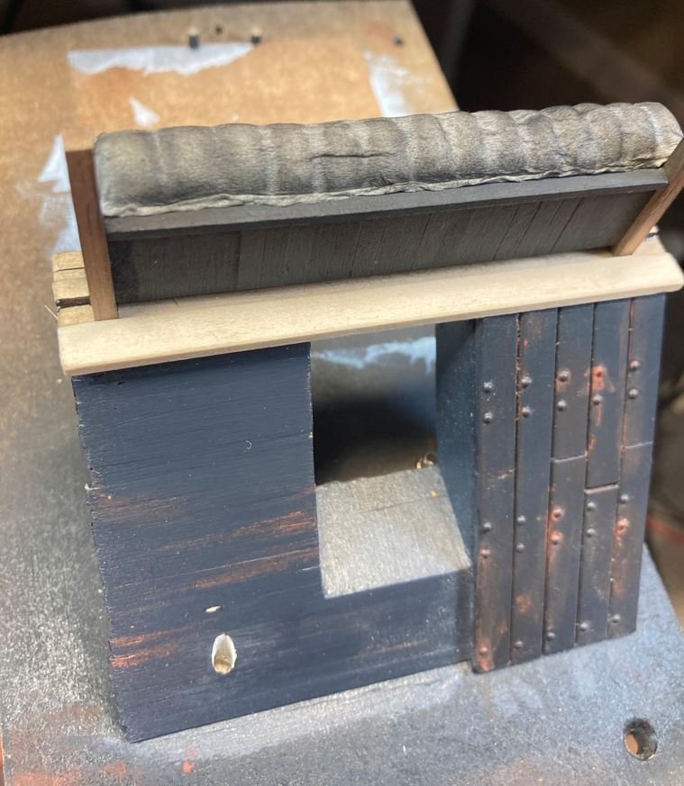
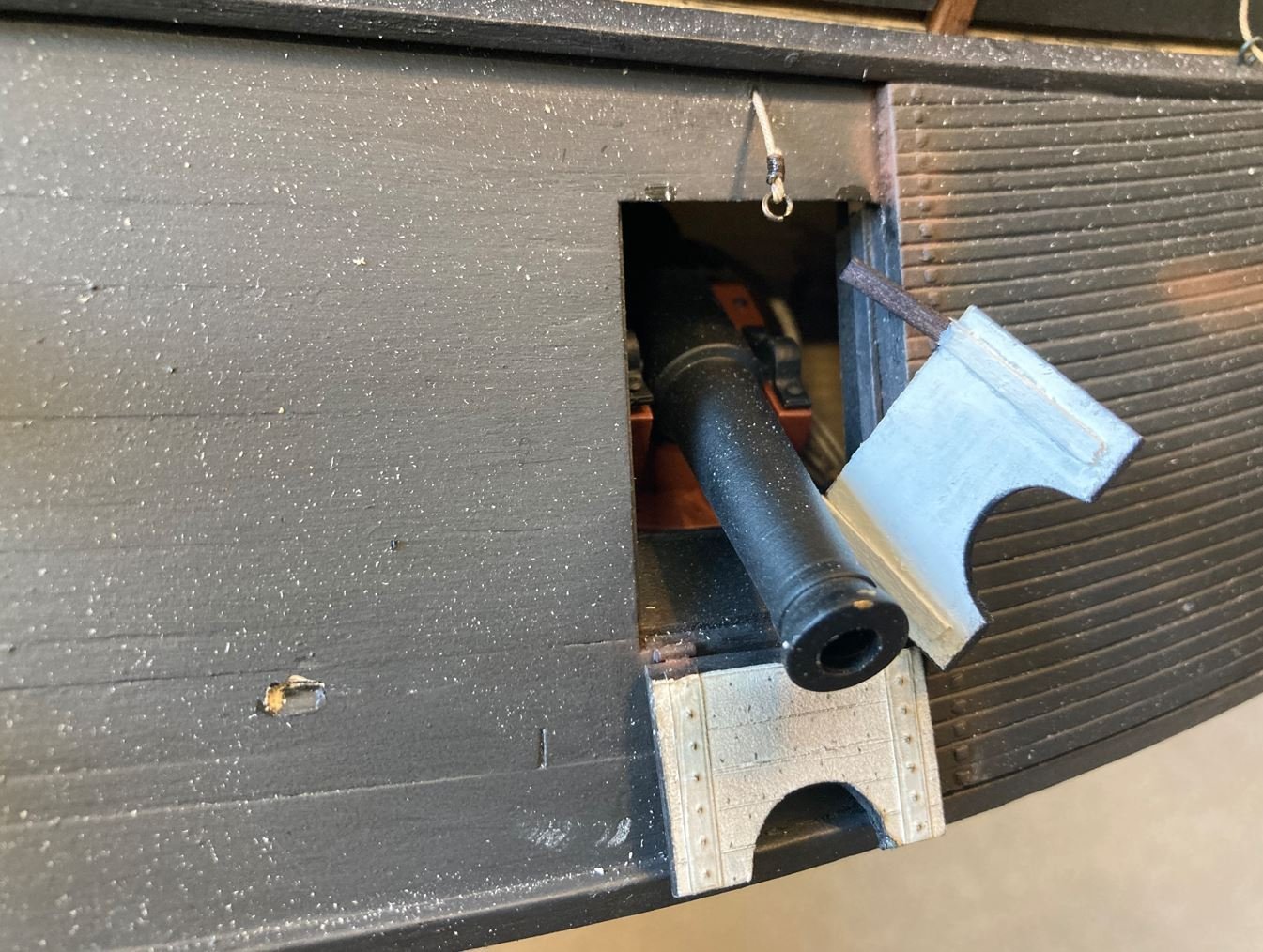
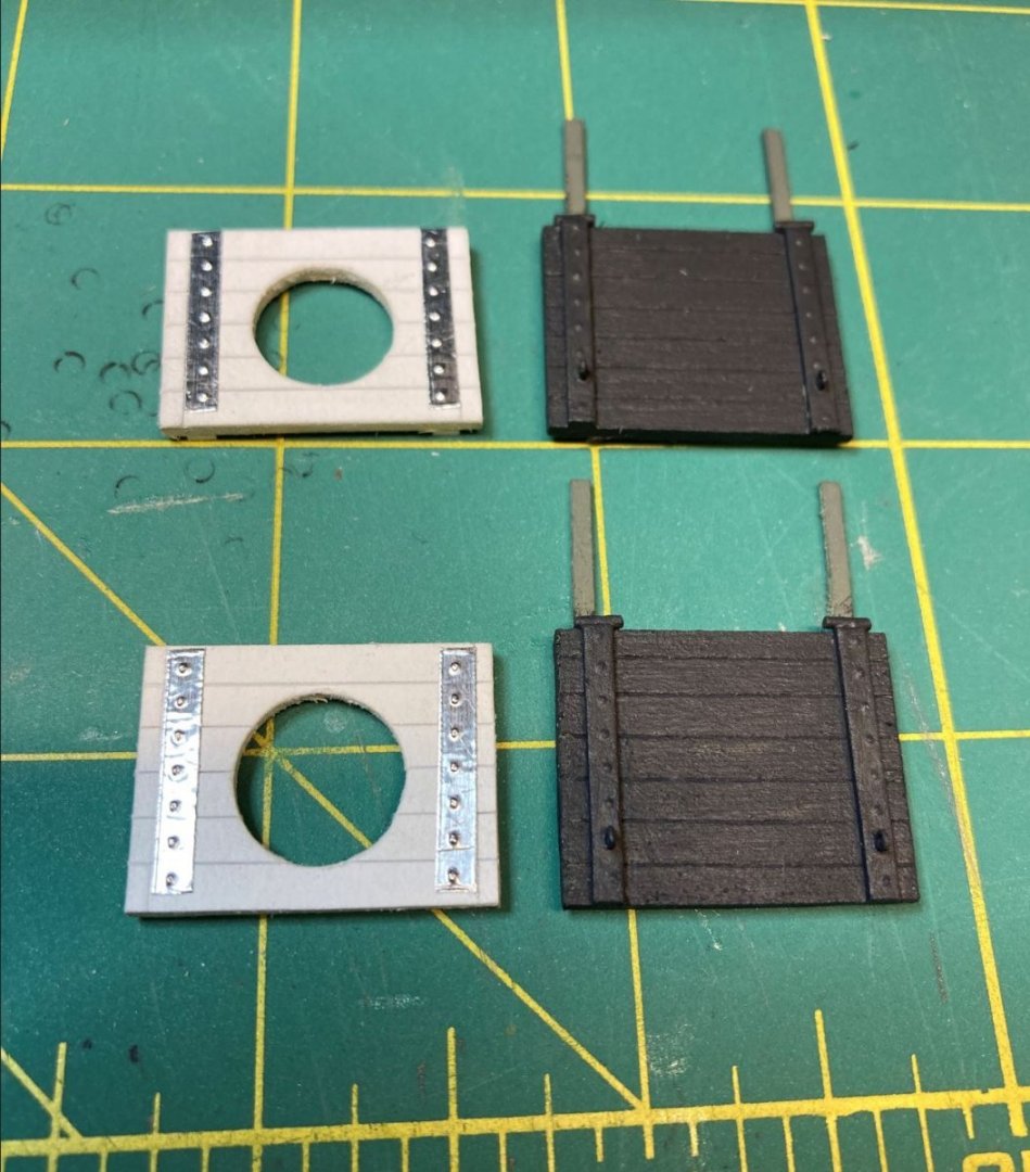
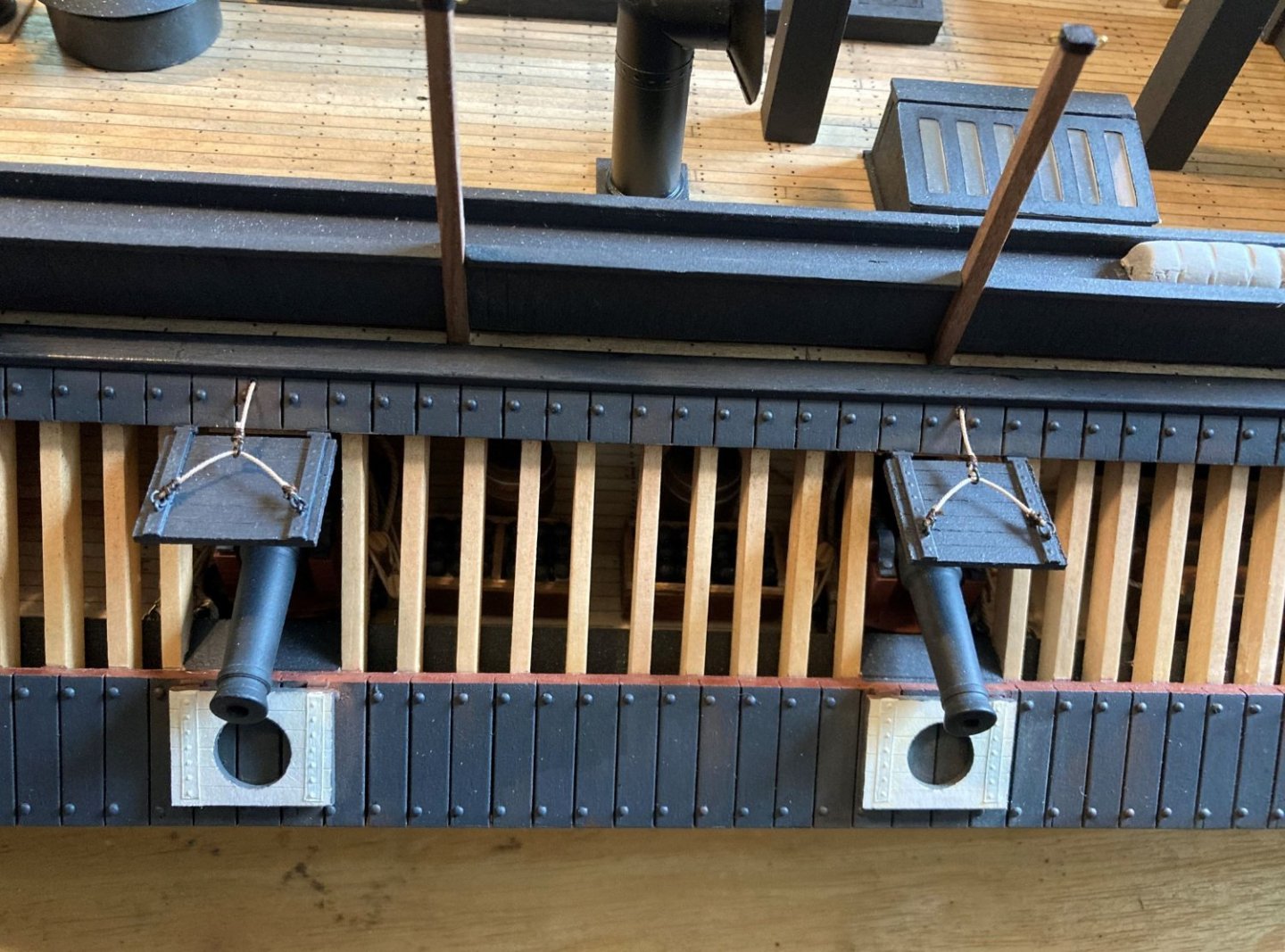
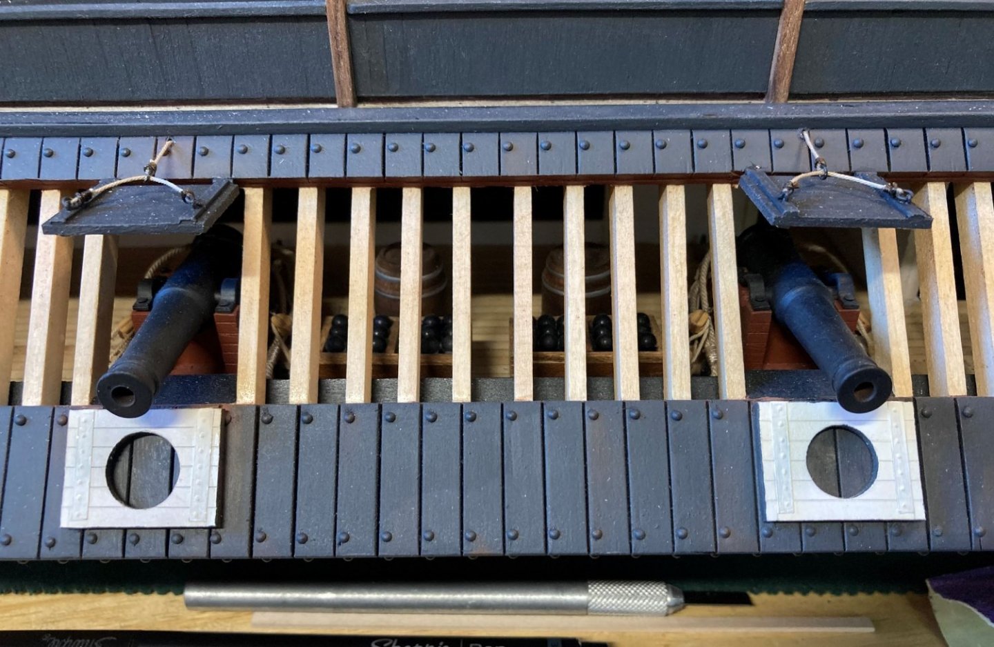
The first redo, were the port and starboard #3 & #4 gun ports. I had built all 13 gun ports the same, with the piercing in between the top and bottom doors. After my trip to Vicksburg and seeing the actual doors (not the ones on the display, these are wrong as well), I discovered that these four doors were designed slightly different in that they have a solid top door and the bottom door is pierced. This was also evident on the contemporary photograph of the Cairo, I had just not noticed it before. I guess I was too busy looking at other areas and overlooked this little detail.
New doors. I cheated a bit on these, with the addition of the tabs on the top doors. There isn't a lot of contact points on the small hinges to glue the doors to the boat, so I placed the tabs underneath and filed out slot in the door frame to receive the tabs. This makes them a lot more stable against accidentally knocking them off while working around them, not to mention it helps hold the doors in the proper position.
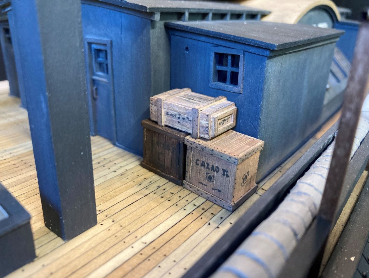
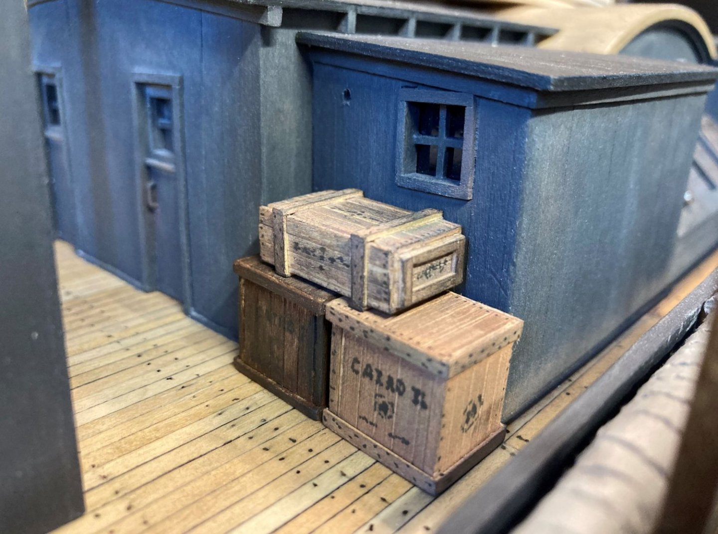
I did do a bit of new work just playing around with some deck furniture. I made up a few crates, to see how they would look. My plan is to populate the hurricane deck with several items. From many of the old photos you can tell that these decks were not clutter free, they were very busy.
The beginnings of one of the crates.
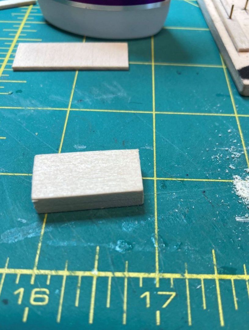
My first attempts all weathered up.
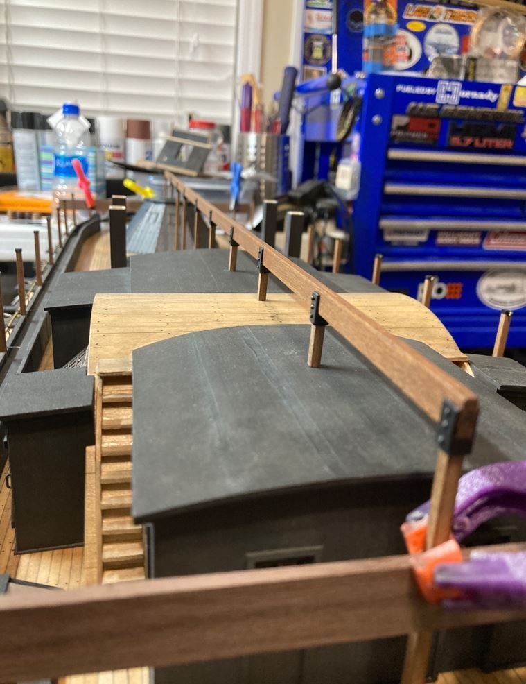
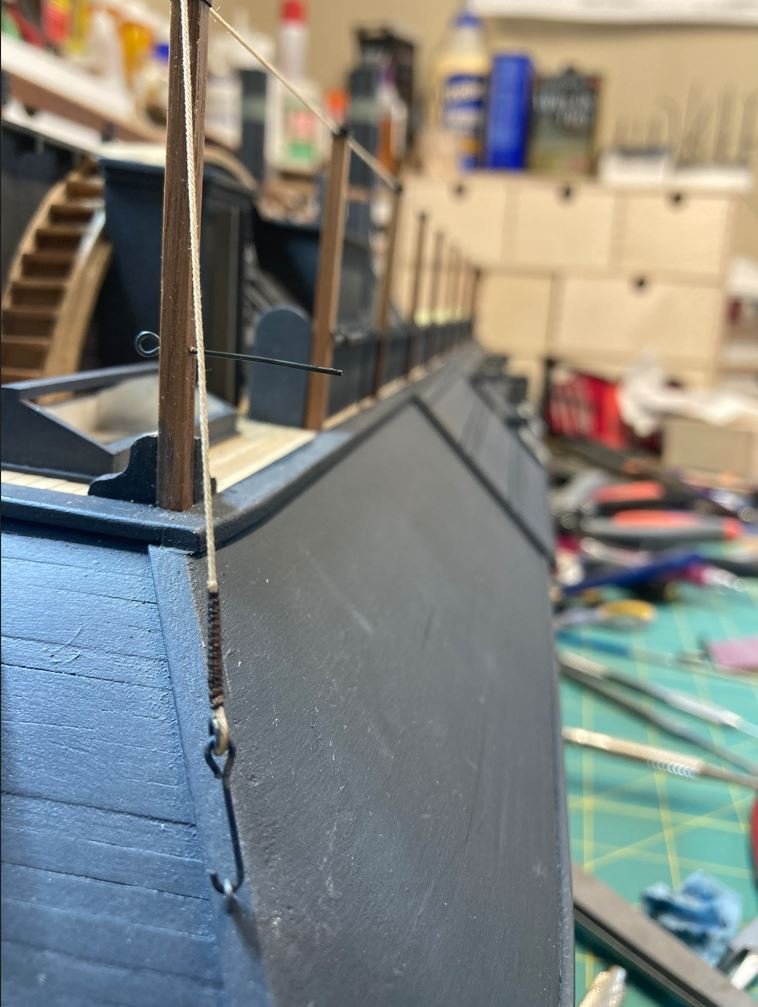
Another redo were the hog chain posts. On the plans the posts are shown to be fairly narrow and sort and I built them according to the plans. After researching these more I found that they were more "beefier" and actually extended above the long beam that runs the length of the hurricane deck and provides a center ridge for the canopies. Not sure of what this beam is called. I didn't take any pictures of the construction of the new hog chain posts, but I constructed a square tube to slide over the existing posts and placed small shims on the smaller ones to fill in the gaps. In the next few pictures you can sort of see what they look like and how I built them. I haven't installed the caps on them yet or the hog chains themselves, I wanted to leave them off until I was finished working on the other rebuilt details of the deck.
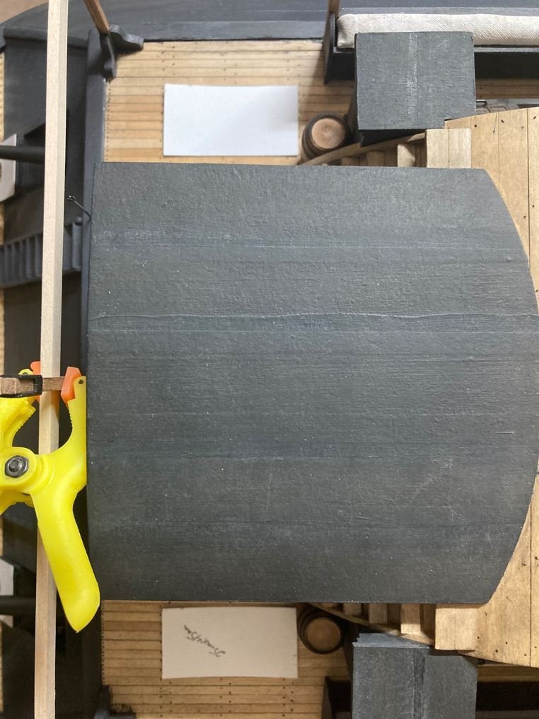
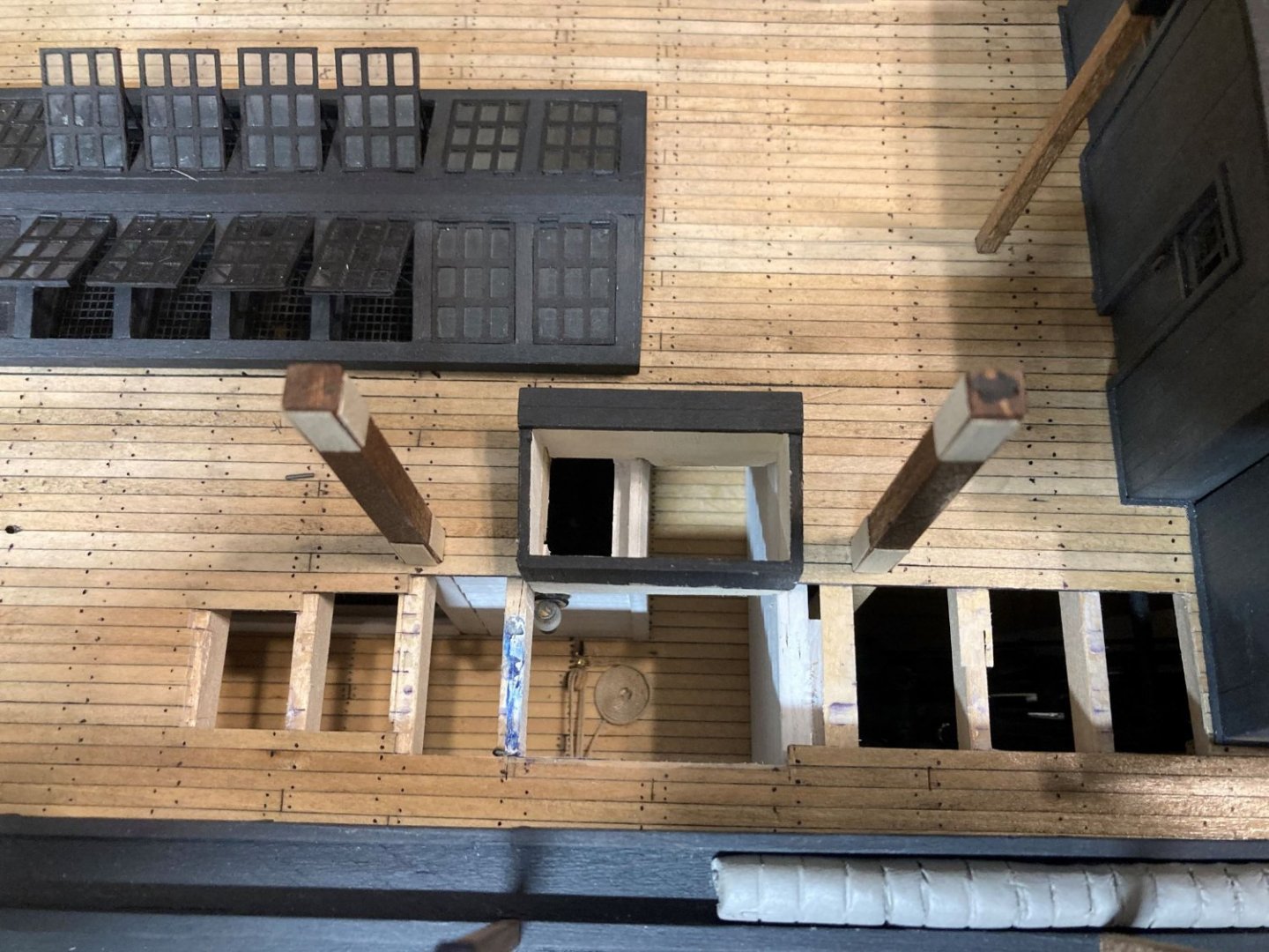
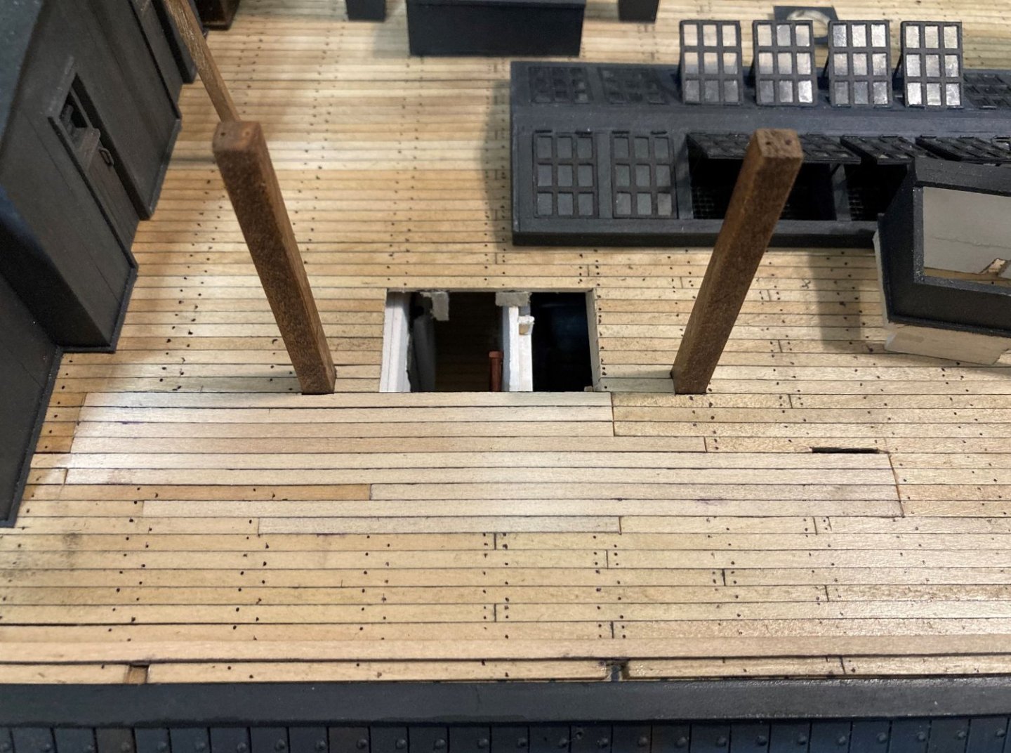
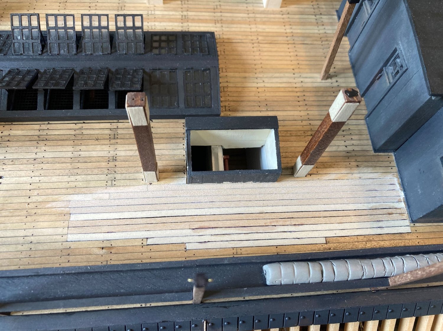
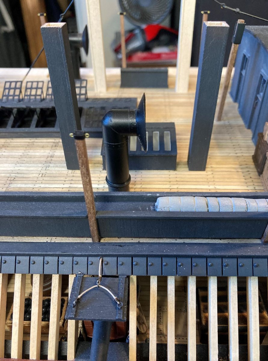
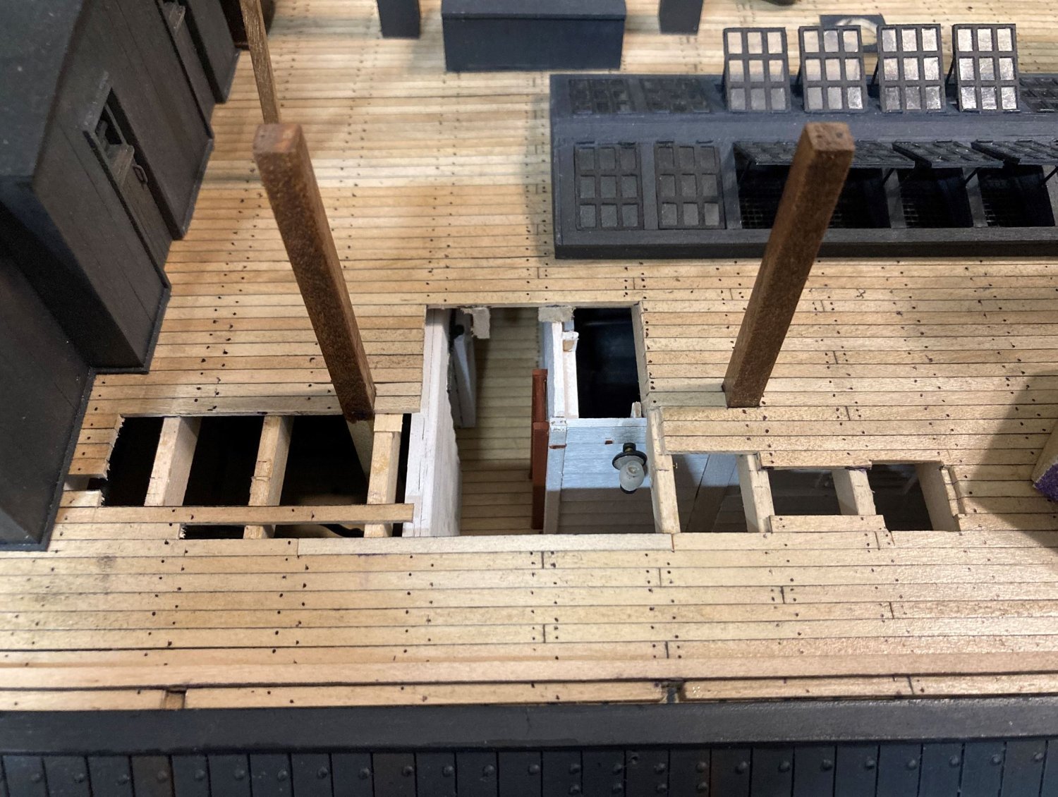
The last bit of rework that I did was the skylight/hatchways and aft funnels. There has been a lot of discussion on my build about this topic lately and I finally think that I have figured out how these were situated on the deck and used.
First off, I believe that I was mistaken in the placement of the aft funnels. I have to agree with Johnhoward that in the old photo of the Cairo, the port aft funnel has been moved from it's normal place on the deck and set aside and that their actual placement is outboard of the hog chain posts and just aft of the forward ones as they are drawn on Ashley's HSR plans. Where I made the mistake was that I placed the skylight outboard of the posts instead of inboard of them. My initial thoughts on this placement was that the inboard wall of the skylight lined up perfectly with the exterior wall of the boiler room. This provided the perfect place for a ladder to go, enabling access in and out of the gun deck. However, moving the skylight inboard actually works better in two ways. One, it moves the ladder to the walkway area between the boiler room and the engine room getting out from directly behind the port and starboard #4 cannons. And two, it places the skylight halfway over the boiler room which allows for a standing platform to place supplies on while hauling it up and down the ladder to the holds.
So I set out removing and replacing the port side deck boards in this area. (note the shims on the hog chain posts).
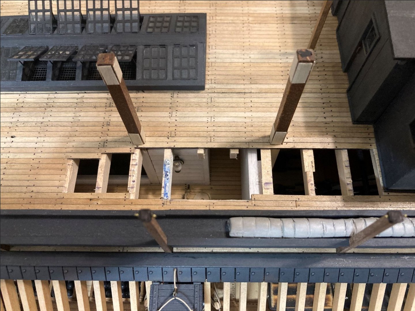
New placement of the skylight. The area on the left side of the skylight is the overlap of the boiler room and where the platform will go.
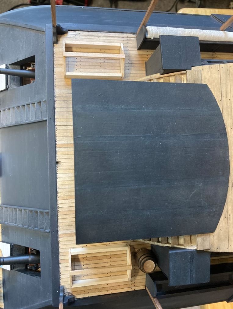
New planking going in.

New planks sanded.
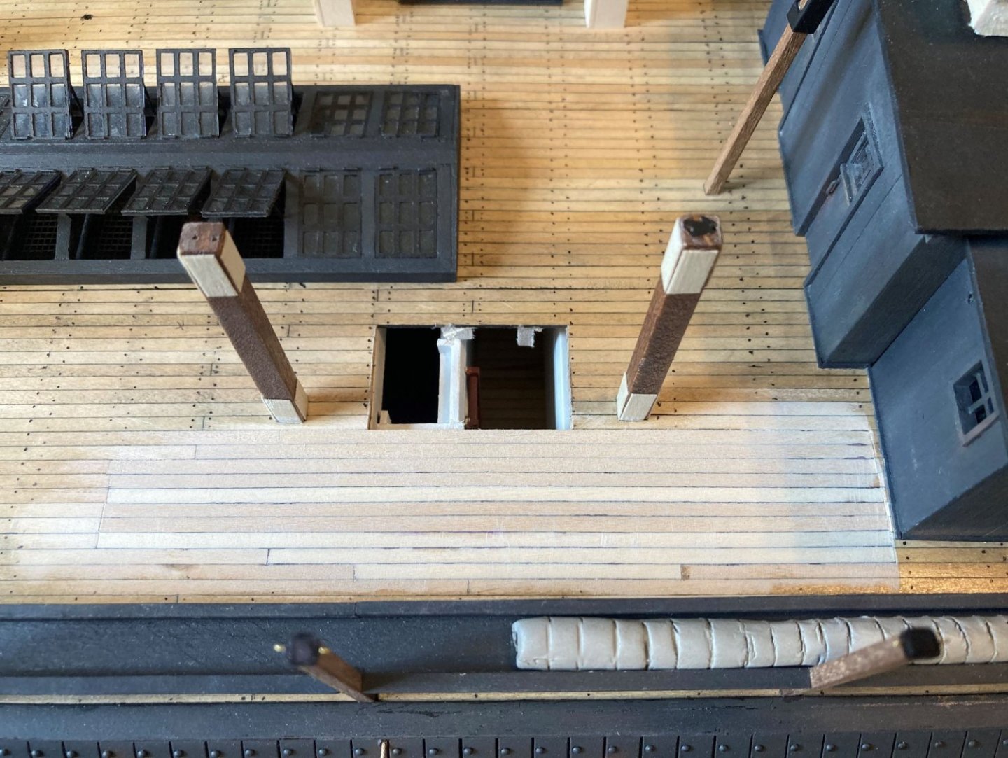
Varnished.

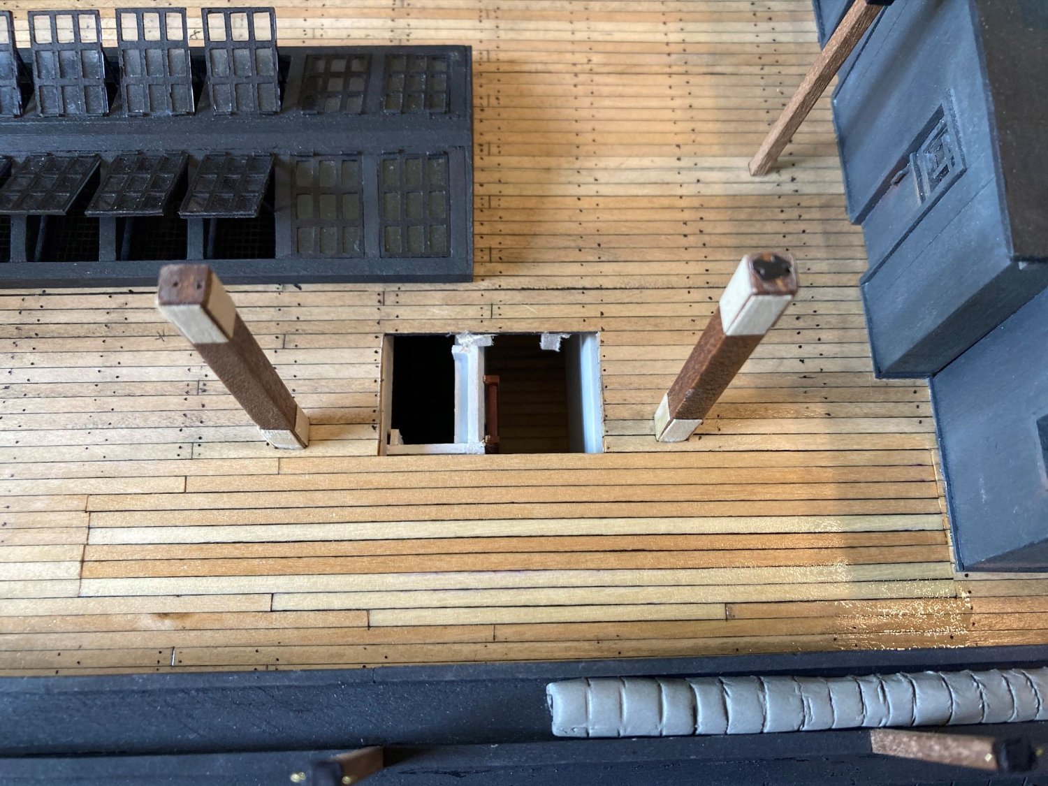
Platform and ladder installed.
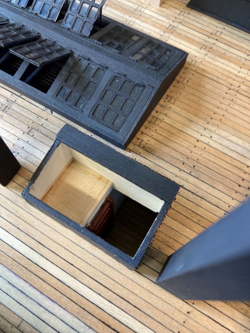
Funnel temporarily installed, deck nails added. All it needs is a bit of weathering and I should be good to go.
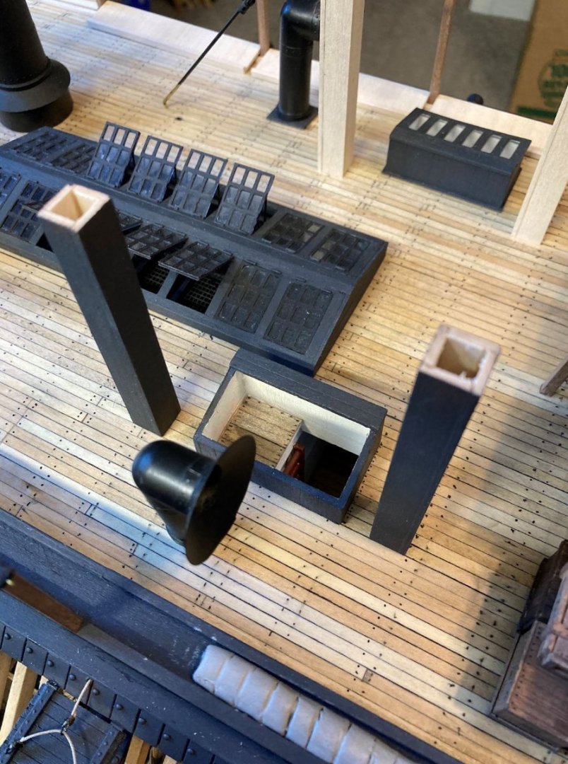

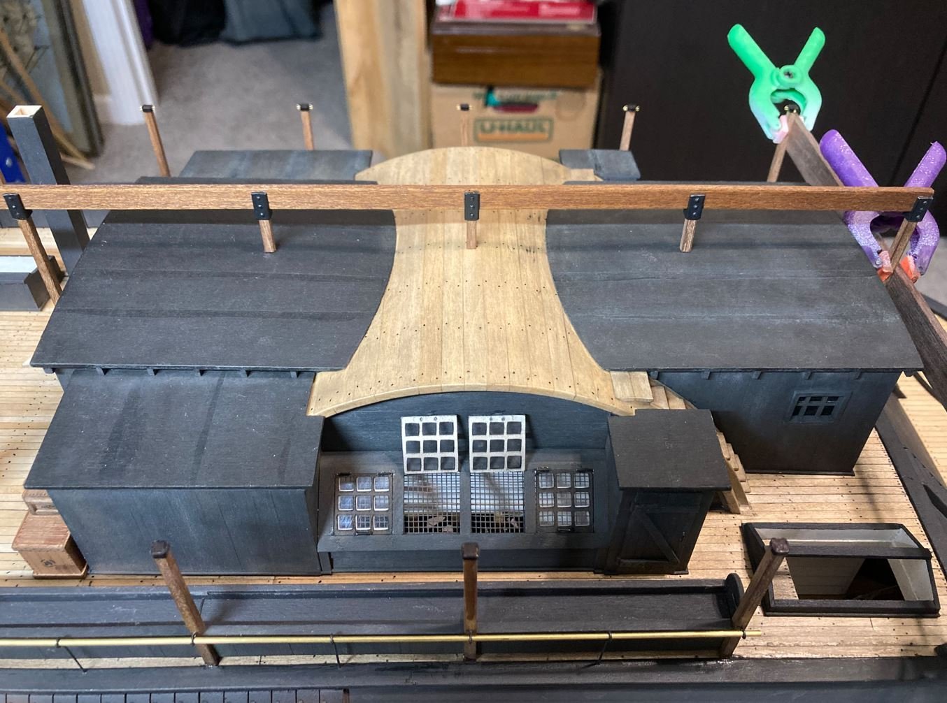
Starboard side being reworked.

Starboard side planks replaced.
And both sides completed. I know that it is ugly right now, but the two areas where the deck board seams all line up will be covered with deck furniture so it will not be seen.
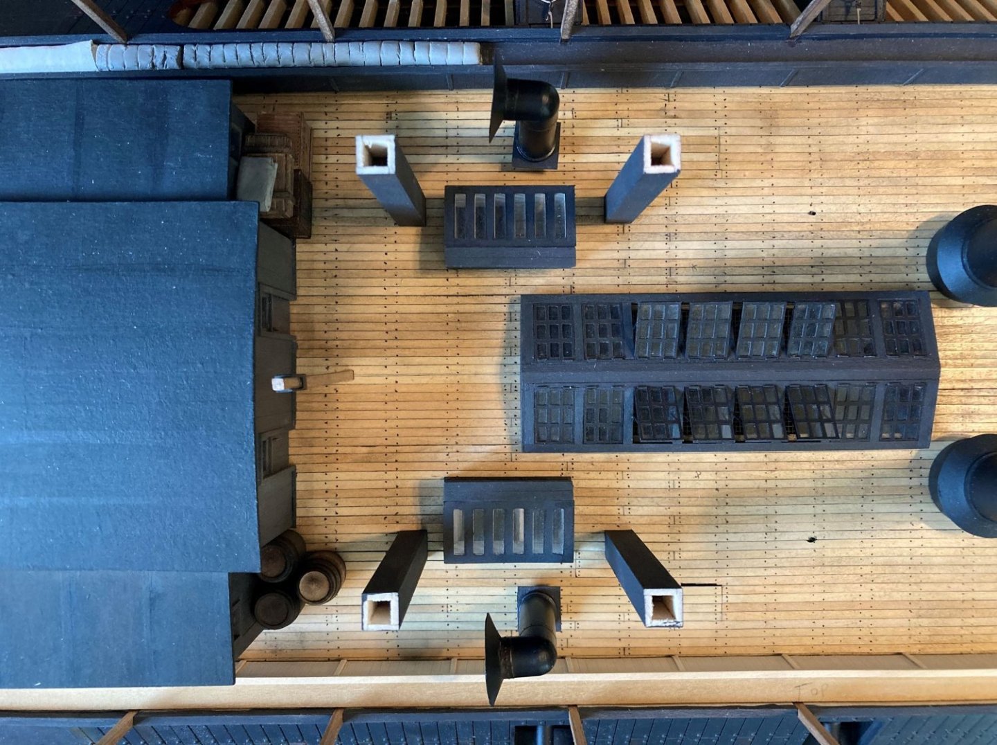
Now I am 100% confident that I have this right. The funnels are where they are supposed to be according to the plans and the skylight/hatchways are installed per the photographs. The interior of the skylight/hatches may not be exact, but there is no photographic or documented proof that I have been able to find of how they were built, so this interpretation seems to make the most sense.
Now on to finishing up the starboard side hammock racks and other deck features.
Thanks to all for the likes and stopping by.
-Brian
- Paul Le Wol, Roger Pellett, berhard and 16 others
-
14
-
 5
5
-
I think I’ve said it before, but it bears repeating. It’s just amazing at what you are accomplishing at this scale!
-Brian
- FriedClams, Keith Black, druxey and 2 others
-
5
-
On 6/1/2022 at 7:22 PM, BANYAN said:
Hi Brian, WRT locks, the magazines, shell rooms and most store rooms (especially those containing flammables and attractive provisions), the 'spirits' store (if there was one) and captain's stores rooms would all have locks also. The sickbay (or medicines locker) may also have had a lock.
Pat, Thank you for the info. It's hard to tell if doors were actually used on the City-Class gunboats for these areas since they were all (with the exception of the medical room) located in the hold. The medical room was supposedly located on the port side of the gun deck, across from the port engine in line with the junior officers quarters. These boats were designed with several hatchways spread throughout the floor of the gun deck to access the compartments from above. It is possible that some of these compartments had a passthrough to the next one and could have had doors on them. Some of the door knobs and locksets could have also come from the structures on the hurricane deck. There were at least four doors located here to access the storage rooms/showers. No telling if there were any other doors located within the structure since this section was all constructed of pine and had long rotted away before the salvage.
A few years ago there was a LIDAR scan done of the boat and they put together a neat little "Fly Through" video of the hold area. It's pretty cool to check out, and will kind of give you an idea of how cramped the hold area was.
-Brian
-
On 5/31/2022 at 11:11 AM, Roger Pellett said:
I would think that a forge would also require a stack, both to provide draft and to exhaust fumes, smoke, and sparks.
21 hours ago, wefalck said:There were at that time so-called field-forges, used by the military. They are essentially a cast-iron basin on legs with a hand-driven ventilator underneath to supply the draught. They have a half-hood in sheet over it to arrest sparks.
Roger/Eberhard,
I would say that there was most likely a forge on board Cairo. Among some of the artifacts recovered were blacksmith tools and an anvil. Unfortunately I have not run across any mention of a forge yet, but with all these tools on board one would think that she carried one. There was a lot of activity on the hurricane deck during their down time, hence the reason for the canopies and the crew was known to have cooked some of their meals on makeshift stoves up on the hurricane deck, so it could be a possibility that the forge was located there and washed down river when she sank. This could explain the lack of additional ventilation from below deck. Just my thoughts.
-Brian
-
On 5/28/2022 at 9:39 PM, johnhoward said:
First about the drawing in my last (#515) posting. This was a cover sheet provided by the SLCWM for Ashley's "HSR" 28 Sheet Set of drawings at scale of 1: 48 for the model they wanted us to build for them at twice that scale or 1:24. This sheet has no title block but is marked in the field as "USS Cairo" , Scale 3/8 ' = 1' 0", ATTERIDGE-83.
Johnhoward, funny that this drawing is more accurate than some of Doug Ashley's, at least in the fact that they got the guy anchor point located in the correct places. Would you happen to have a full picture of these drawings to share? I'd like to get a better look at the overall drawings to see how the SLCWM interpreted the design.
On 5/28/2022 at 9:39 PM, johnhoward said:While building the USS St. Louis at the large 1: 24 scale we discovered numerous physical inconsistencies between Ashley's drawings alignment of the individual decks. One of these was the location of the aft Ventilation Funnels shown in your previous Gun Deck/ Hurricane Deck Overlay drawing. Our initial interpretation determined that your light blue parallel lines actually depict the cross-over walkway mis-located too far forward by about one width space. Your red line is not a full wall but is actually a short open hand railing on the aft side of this crossover walkway, with an opening in it for a short stairway down to the floor of the engine room. The light blue circle obviously represents the ventilation funnel but we believe it is actually also aft of the boiler room wall further aft over the open cross-over walkway. Since the walkway is also probably has a fine open grated surface it wouldn't disrupt its ventilation affect..
This is a tough one. During the salvage there were numerous door knobs and locksets recovered and one almost fully intact door. The door is believed to have come from the captains quarters, however, there is no explanation of the other door knobs and locksets. Where did they come from? Could these have been from the junior officers quarters? Some descriptions of the junior officers quarters are they were made of canvas walls that could be taken down expediently, so it seems that there would be no need for doors there. My other thoughts are there had to be other doors somewhere else on the ship, Possibly access doors from the gun deck to the boiler room or engine rooms? There is written documentation that when the Cairo was refitted with the railroad irons on her forward casements, the crew also used some of the same materials to fortify the boiler room walls on the gun deck to prevent a catastrophe similar to the one on board the Mound City. Since there were walls along the sides of the boiler room, would there be the possibility of doors along these walls allowing access to the fire room from the gun deck as shown in Ashley's plans? if so, this could account for at least two other doors. Where were there others?
The walkway between the boiler room and the engine room was the location of where one of the cuts were made by the salvagers when they decided to bring the boat up in three sections, so not a lot of this area survived. Personally I believe that some of the documentation of this area is left to interpretation by Ashley. It was also through this area where the "Doctor" pump was lost and the skylights & aft funnels were as well, so there is no telling what else fell out when this section was brought up.
Some photos of the center piece of the boat being recovered showing the aft side of the boilers and the steam drum coming up. In the first photo, you can make out what looks to be a solid deck running behind the boiler tubes, Not sure if this would be that walkway or not, but it is possible. The skylights and the aft funnels would have be located in the area that is sitting on top of the barge,
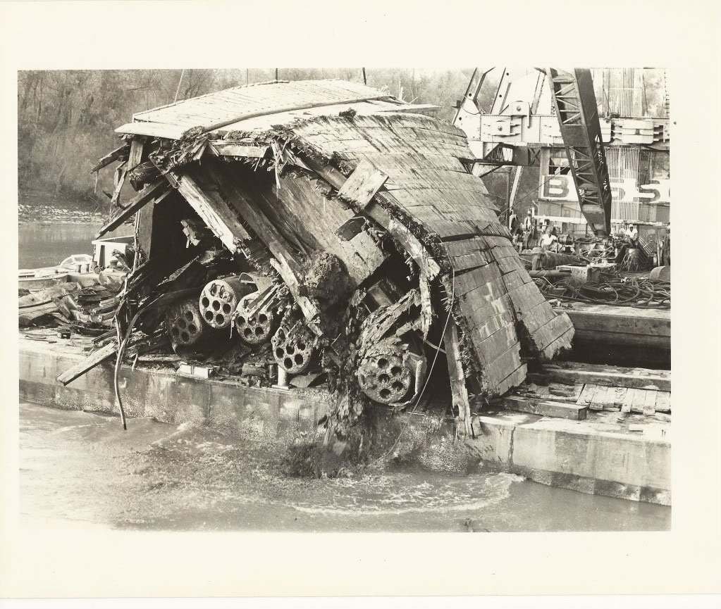
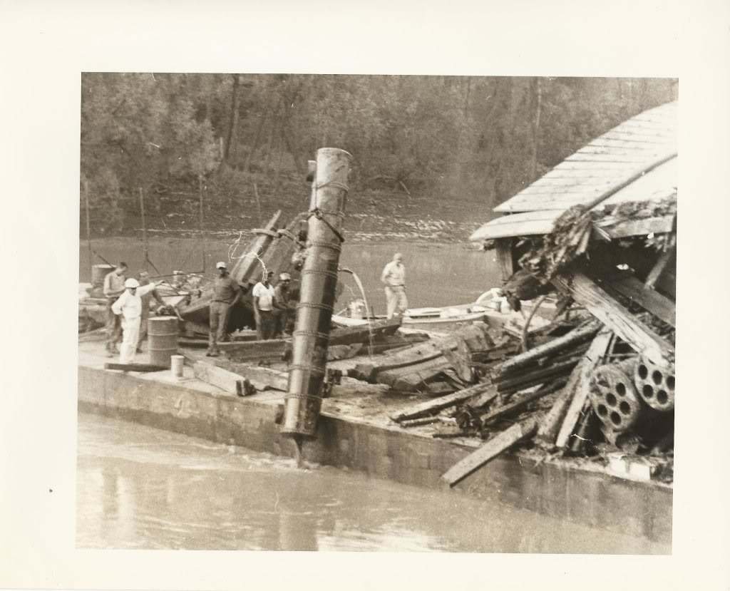
These pictures bring tears to my eyes sometimes. Man did these guys make a mess of the recovery.
-Brian
-
That would be an extremely nice addition, but you are correct sir, a tad bit too rich.
-Brian
- Dave_E, FriedClams, Keith Black and 1 other
-
4
-
-
Eberhard, your patience on these small boats must be commended. It was all I could do to maintain my sanity making my four ships boats at 1:48 scale. At 1:160 scale they would have to carry me out in a straight jacket drooling and babbling to myself. Amazing work. Looking forward to the next installment.
-Brian
- FriedClams, Keith Black, mtaylor and 1 other
-
4
-
Loving the progress John. Beautiful work.
-Brian
- bobandlucy and John Ruy
-
1
-
 1
1


SMS WESPE 1876 by wefalck – FINISHED - 1/160 scale - Armored Gunboat of the Imperial German Navy - as first commissioned
in - Build logs for subjects built 1851 - 1900
Posted
Beautiful work on the Cutter Eberhard. I have been playing around with simulating tarps as well. I don't have any Japanese silk paper on hand, but so far I have found that two-ply Kleenex saturated with a 50/50 water and Elmer's glue solution has been working great. Glad to see that you are healthy and back at it.
-Brian