


mbp521
-
Posts
989 -
Joined
-
Last visited
Content Type
Profiles
Forums
Gallery
Events
Posts posted by mbp521
-
-
23 hours ago, Roger Pellett said:
If “digital replacement” becomes a selling point, you need to replace that Craftsman full sized table saw with a SawStop table saw. That’s a Rabbit Hole involving $$$$!
Roger, I had looked at those several years ago, but they were way too expensive. They are also proud of their saws as well, and having to replace the cartridge every time it was used can get a little pricy.
23 hours ago, Roger Pellett said:My full sized table saw is a 10in Delta Contractor’s saw bought for $150 from a local canoe builder who upgraded to a SawStop. The sale price included a trailer to haul it home!
What a steal! I bought my Craftsman about 20 years ago and paid about $1500 for it, and that was the floor model. Not to mention it didn't come with a trailer. Had to haul it home in the truck and have three friends help unload it. 😁
-Brian
- Canute, Keith Black and mtaylor
-
 3
3
-
Eric I’m starting to get the feeling that the instructions for this model are not very useful. This may be a build as you go and use the instructions just for parts placement.
The side casement armor does indeed sit under the hurricane deck trim/water ways. It overlaps the armor plating, I would guess to keep most of the runoff from going between the plates and the casements.
I noticed that the forward railroad irons do the same thing that I had an issue in with my build where the top few rows tapered up into the hurricane deck trim. Later on in my build I found the reason for this was that the angles between the forward casements and the side casements were different. The HSR plans have both casements at a 45 degree angle but later research shows the forwards were 35 degrees.
I love the toddler tenacity of wanting to work on your model right now! 😁
-Brian
- bobandlucy, Keith Black, Canute and 2 others
-
5
-
2 hours ago, KeithAug said:
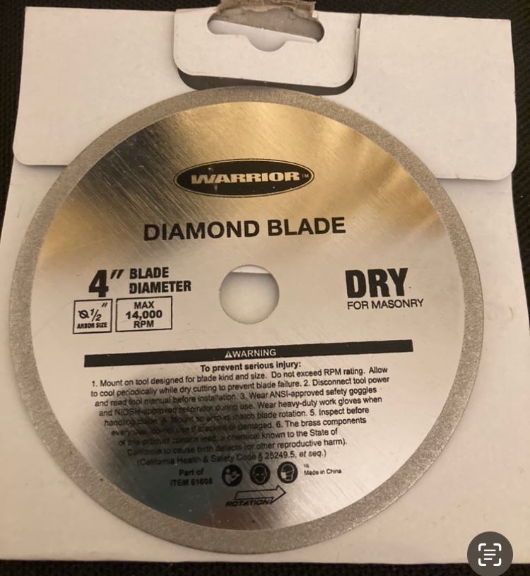
That is interesting, could you provide more information on the diamond blade and perhaps where you purchased it from.
I can’t speak for the UK Keith but over here we have a place called Harbor Freight. They sell tools really cheap, but of course they are cheap. Several years ago when I first got into wooden ship building I purchase one of their cheap mini table saws for something like $20. Needless to say, you get what you pay for, and it wouldn’t cut a clean line for anything. Long story short, it came with a diamond blade, but it does say for masonry. Never thought to try it on wood.
 2 hours ago, KeithAug said:
The advantage of the Byrnes saw is that the amputation is much cleaner, which facilitates the process of surgical re-attachment.
Good to know that digit reattachment is easier with the Byrnes. Good selling point. I sure hope this information doesn’t come from personal experience though. 😁
-Brian
- Canute, Cathead, Keith Black and 2 others
-
5
-
Beautiful work Greg! Definitely an interesting subject, but it looks great.
-Brian
- Canute, popeye the sailor, mtaylor and 4 others
-
7
-
29 minutes ago, kurtvd19 said:
Do you have a zero clearance insert for your saw blade? The use of one for each saw blade cuts down on the splintering on plywood. Makes a much cleaner cut. Tell your wife that the Byrnes saw is a matter of saving your fingers. While it is quite capable of taking off a digit or two it being smaller and sized to the work you do with models makes it safer to use than the big shop saw.
Hi Kurt, unfortunately I do not have a zero clearance insert for my saw. I had never really thought that I would use the saw for small detail work like ship modelling. However, that is something that I will look into if I can't swing the Byrnes for a while. I'll definitely bring the finger saving idea up to the wife though. If no one hears anything from me for a while I may be recovering from a mysterious frying pan upside the head accident. 😁
-Brian
- Canute, Keith Black, FriedClams and 3 others
-
3
-
 3
3
-
16 hours ago, Alex-Ks1 said:
I have a precision small table saw, it uses a very thin diamond blade, this dose not put the rips in the wood, it looks more like it was uses with a hot knife. Very smooth, no rips,
Alex-Ks1, thank you for stopping by. I have been eye-balling a Byrnes precision table saw for some time now, it just hasn't been in the budget as of yet. I cut the bulkheads on my Craftsman 10" Industrial table saw from 1/4" plywood, with a brand new carbide tipped blade. Even with a new blade I just couldn't keep the plywood from shredding. Of course the plywood was not of the best quality either, but this is the reason for all the tear-outs. Fortunately all the bulkheads were hidden and none of the "nastiness" of the plywood can be seen. For the finer stuff, I used an Xacto saw blade and a lot of sandpaper. One of these days I may be able to talk the Admiral into a Byrnes (fingers crossed).
-Brian
- mtaylor, Canute, Keith Black and 2 others
-
5
-
11 hours ago, Cathead said:
I've always used Model Expo paints in the past, I'm used to them and a creature of habit. But I'm out of paint and needed some different colors. This time I switched to ordering some Vallejo primer and colors from MicroMark.
Glad to see another update. I’m not a huge fan of ME paints. They do have some nice colors that are, for the most part, true to some of the originals, but I find them a bit thick and in need of thinning before applying. I love the Vallejo paints. They have so many more color options available and they apply nicely right out of the bottle.
Fantastic job on getting the hull shaped, and I love the plan you have to weather the deck. I’m a big fan of natural wood decks. I wouldn’t sweat the PE too much. I found that it was easier to work with than I first thought as well. Well, at least the bigger parts are. Haven’t had the joy of working with the tiny stuff yet. 😁
-Brian
- mtaylor, Cathead, Keith Black and 1 other
-
4
-
8 hours ago, Zetec said:
Hi I came across your build site as I was looking for information on the USS Cairo that I have just started to build. What a lovely model you have built. You must be very proud of what you have achieved. I only hope mine will come out looking something like yours this now gives me a bench mark to aim towards.
Thank you John for the kind words. I see that you are new to MSW and I hope you are planning to do a build log on your model. There are so many wonderful resources here at MSW and I would love to follow along and help out where I can.
- Brian
- bdgiantman2, Keith Black, Canute and 2 others
-
5
-
-
Nice quarry Eric. Looks like the freezer is beginning to get stocked.
-Brian
- Keith Black, FriedClams, Baker and 4 others
-
7
-
Looking beautiful Tom. I use the CA on the thread method all the time. It certainly helps when threading the smaller ropes through the blocks.
-Brian
-
Nice work on tying down the dingy Keith and nifty idea to plumb the masts. I'll need to keep that in mind on my next masted ship build. As I view your log, I sometimes have a hard time believing that this is a model. Your details are amazing.
-Brian
- Keith Black, mtaylor, Knocklouder and 2 others
-
5
-
-
@Roger Pellett, @leclaire, @wefalck, @Canute, @KeithAug, @mtaylor, @Keith Black Thank you all for your input and suggestions.
So I spent the evening playing around with different methods and here is what I came up with.
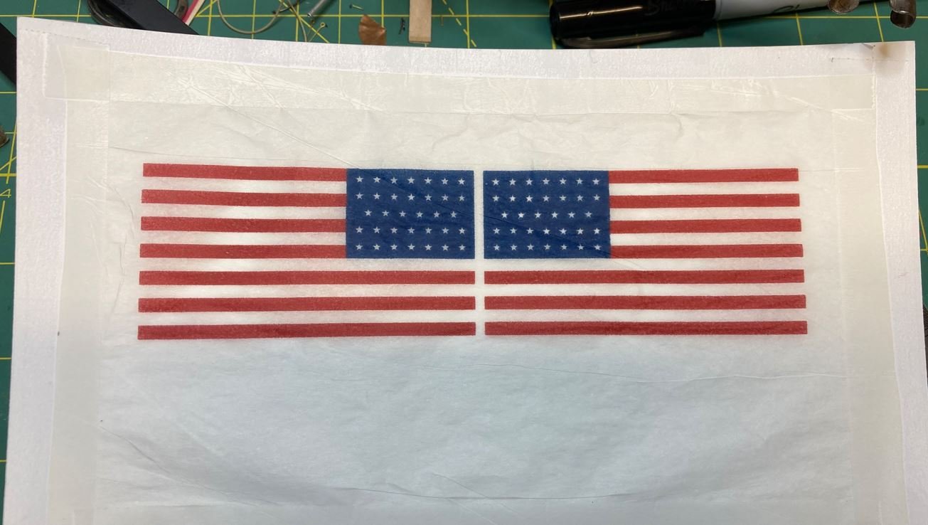
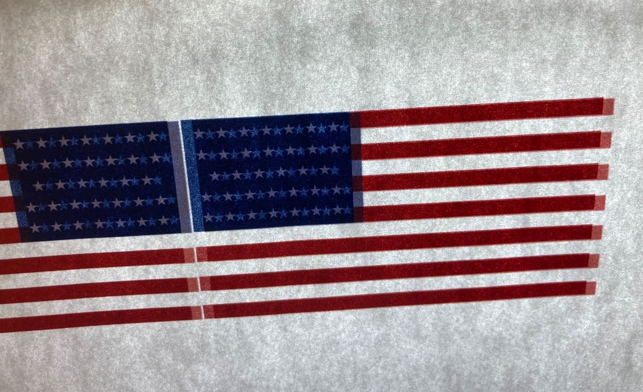
My second attempt was to try printing the flag on silkspan just to see if the ink would bleed. Turns out that the printer did a fantastic job on the silkspan and the lines came out nice an clean. I taped the silkspan to a piece of cardstock to hold it in place so it wouldn't crinkle up under the printer head.
Then I separated the printout from the cardstock and trimmed the edges after a bit of weathering. I wasn't too keen on the color of the white areas on the silkspan when I pulled it off the cardstock, it looked a little too gray, but when I folded it over the gray toned out a bit and it looked a little more white.
The silkspan that I had on hand was very thin, something left over from a balsa airplane I made years ago. But I figured I'd give it a shot, so I slathered some glue on the back side and folded it over to glue the two sides together. That is where I screwed it up. The glue thinned the silkspan down so much that it was next to impossible to work with and when I went to align the side it just smeared and ruined the whole piece. So on to the next method.
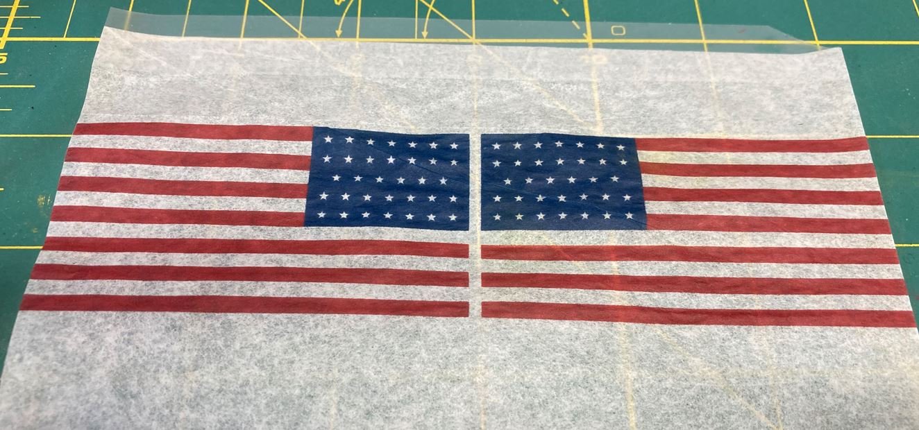
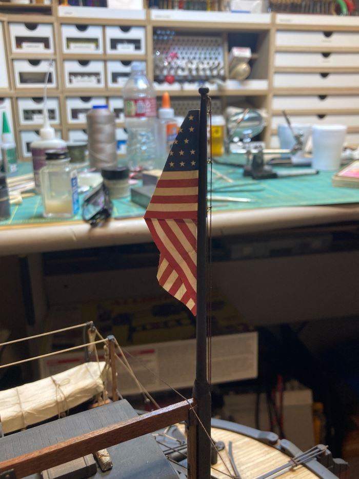
The next method I tried was @KeithAug suggestion to print the pattern on both sides of the paper and just make the flag a single layer. I printed out about five versions of it before I finally gave up. My poor cheapo printer just would not line the paper up when I would turn it over to print the other side. This was the closest I could get the sides to line up with each other.
I went ahead and gave it a shot anyway to see if I could distress it and get it lay the way I wanted to without using any glue. The distressing looked great, but the paper was just to flimsy to lay right. So I moved on to the next method. Parchment paper. Well needless to say, that method didn't work either, The parchment paper was too crinkly and when I went to shape it the wrinkles were just too unrealistic.
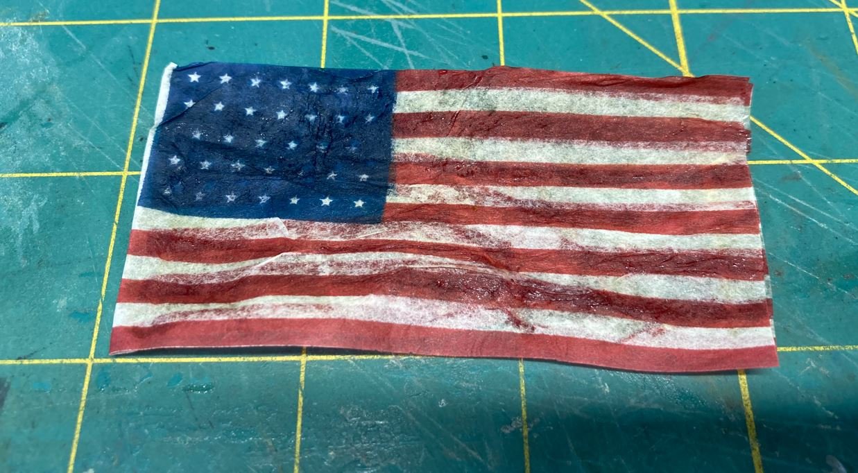
So finally I decided that I would make another attempt at distressing the printer paper like in my beta test. I liked the way this version looked aesthetically, I just wasn't happy with the way it was hanging on the halyard. As Eberhard pointed out, the angle was not natural, so I redid this method to place the header down the middle of the flag and have it hang more centered on the mast.
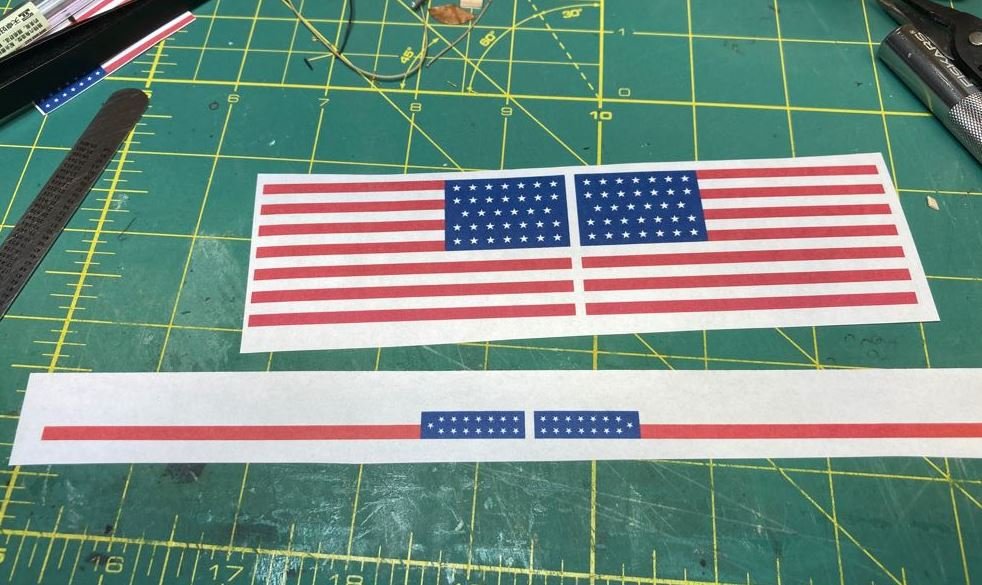
Here are all of the attempts I made, just to show the differences.
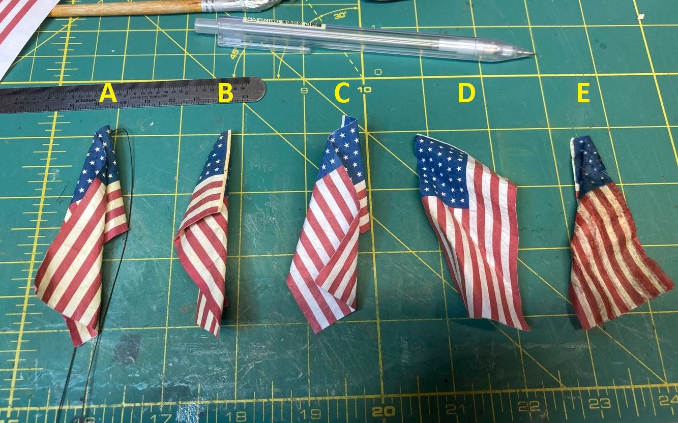
A. second version of distressed bond paper. I added a little more weathering than the beta version, but I liked the curl and hang a lot better.
B. The beta test
C. The single layer
D. Parchment paper
E. Silkspan
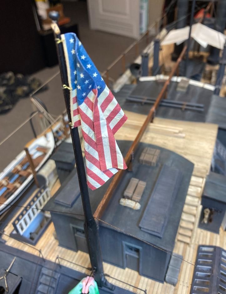
Here is version A placed on the model. I like the way that it hangs and I think the weathered patina looks just right,
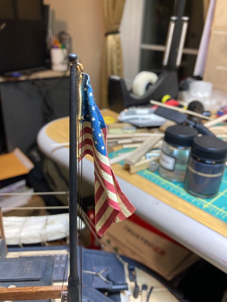
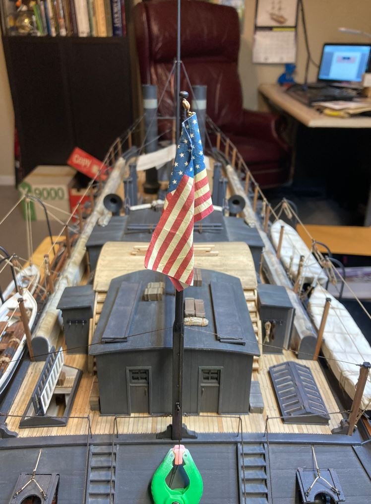
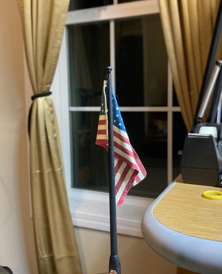
I found some pictures online of flags sitting on stages in flag stands to get the drape right, and used these to mold my shape. On the western rivers, there was always some sort of breeze, so the flag wouldn't be sitting perfectly still or hanging against the mast. So I took this into consideration and left the left the bottom of the ensign hanging slightly out from the mast, just to give it some "life". I think I am completely satisfied with this version, and now that I have beat this subject to death. time to move on to the pennant.
Thank you all so much for your valuable input and suggestions. It is greatly appreciated.
-Brian
- Nunnehi (Don), BANYAN, hollowneck and 14 others
-
17
-
aaaaaaaaaaaaaaaaaaaaaaa Sorry, my jaw just hit the keyboard. 😁
Beautiful details Keith. Craftsmanship like yours is what I strive to someday achieve. Truly inspiring!
-Brian
- mtaylor, Wintergreen, FriedClams and 2 others
-
4
-
1
-
10 hours ago, Roger Pellett said:
Stiff paper flags can ruin the appearance of a well built model and your beautiful model deserves lifelike ones.
Thank you Roger, I agree 100% with this statement. Never would I even think of putting a stiff paper flag on any model. It's almost blasphemy to spend that much time on a build only to tarnish it by slapping a unrealistic flag on it.😁
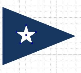
Actually you brought up one of the methods from the NRG that I was going to try. I was going to deviate slightly from the method and attempt to see if the Silkspan would hold the ink from my printer first without bleeding. If it does bleed, I may see if I can locate some rice paper and try that. I've never dealt with rice paper before, but there is always a first time for everything. I am not real confident in my painting skills and getting straight lines, but there is always the need to improve a skill I'm lacking in. However, the star field is what's holding me back from painting. 34 small stars (at 1:48 on a 6' x 10' flag are about 2mm across) and doubling that for both sides would test my patience to the max. I may someday try painting one on a more simpler pattern such as the Union Jack, I just don't think I'm ready with this one. Not to mention with the eyes that are on me now, I want to make sure that I get it done right so I don't disappoint.
7 hours ago, mtaylor said:Another way to get natural looking flags is take an aluminum can, open it flat. Then bend it to the desired shape for the hanging flag. Put the flag on the shaped can and soak with white glue/water (if printed... test to see if the ink runs) and press into the can to shape. Let dry. I used that on my Constellation and Wasa and the flags came out very well, IMO.
Mark, Thank you for the suggestion. This is not a method that I have run across yet and will definitely take into consideration if I am not able to achieve a natural look.
6 hours ago, KeithAug said:Brian I'm looking forward to seeing and learning from your flag experiments. I think it is time you stopped pretending this is your first scratch model, you are fooling no one😁.
Keith, no pretending here. This entire build has been a learning experience. 😁 But, pull up a chair while I run through my first attempt at flag making.
With this much attention I decided to go ahead and get my beta test posted and get some input (positive or negative) from everyone. So here goes.
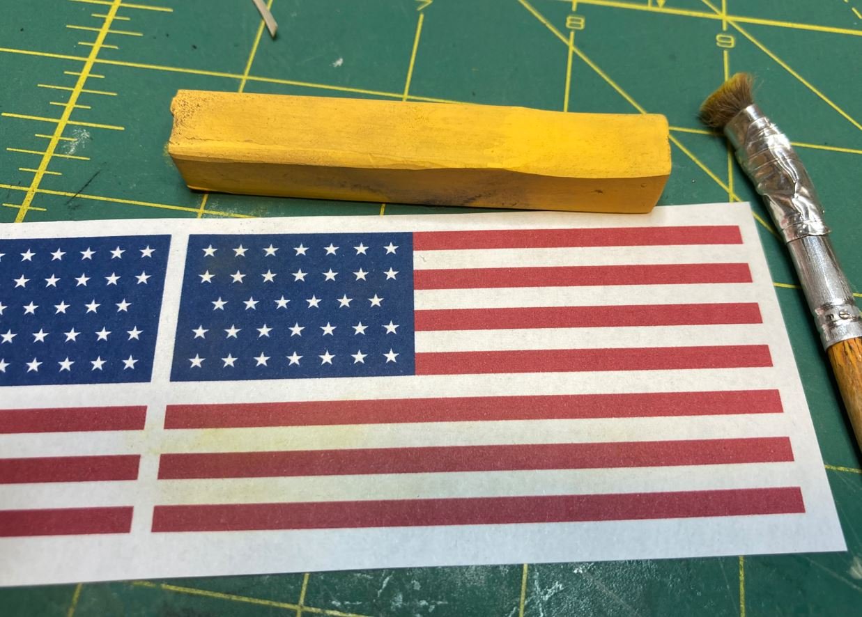
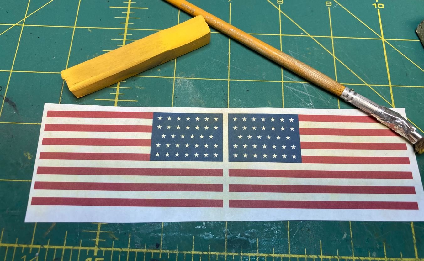
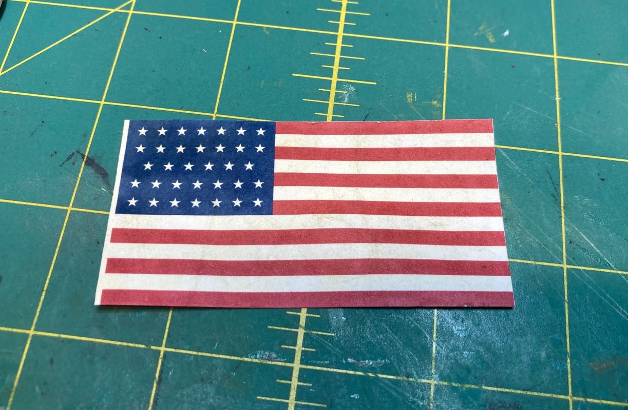
I started with printing out the ensign on just some plain white printer paper. Not a heavy bond, just lightweight so that the flag wasn't too thick and easy to work with.
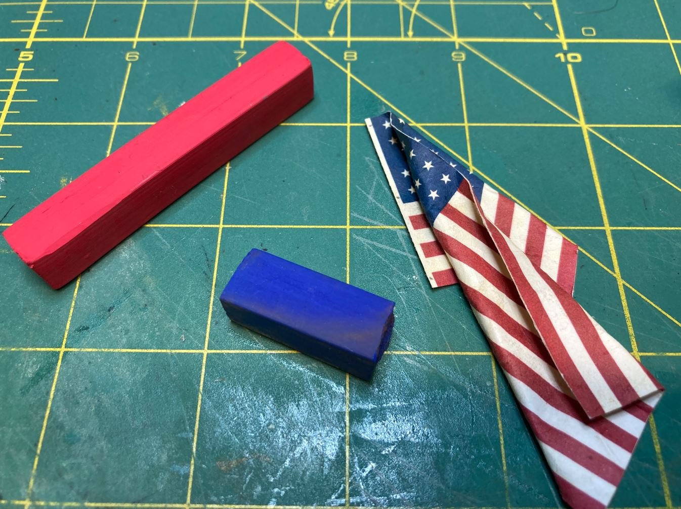
I took an ochre chalk pastel and lightly brushed on a little color to give it a stained/weathered look and take some of the sharpness out of the white and dull down some of the blue and red.
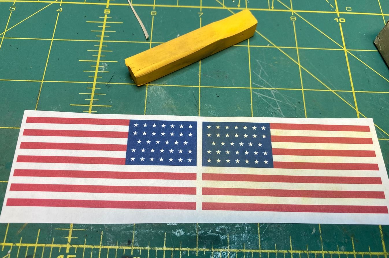
Both sides aged a bit.
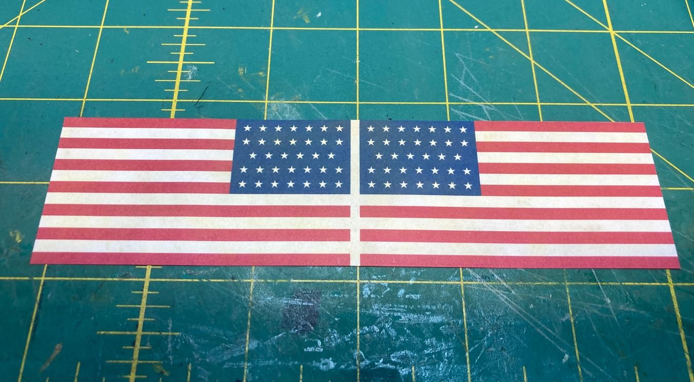
Then I trimmed away the excess paper get the full shape of the ensign.
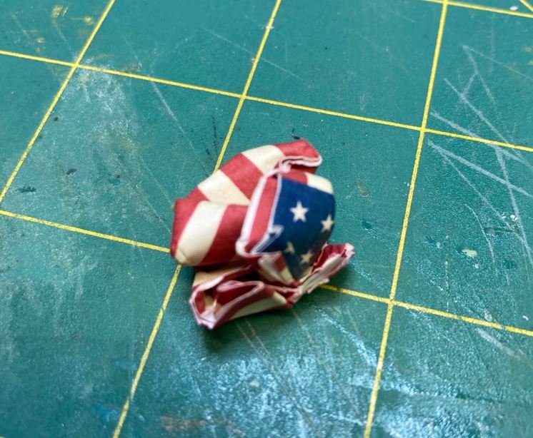
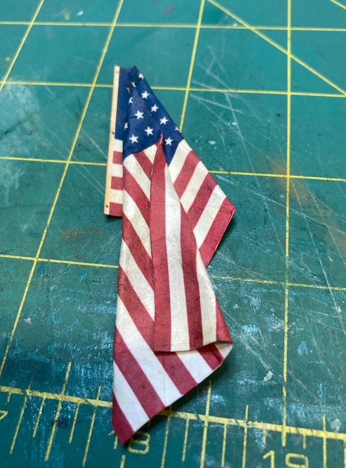
This next step was really hard for me because it seemed a bit disrespectful to do this to the flag, but I kept telling myself, it's only temporary and part of the process to show it off properly. I wadded the paper to soften the fibers and make it look a lot more like material.
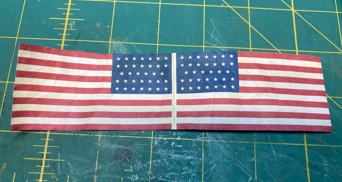
After unravelling it, I pulled it across the sharp edge of my desk to help smooth out some of the harsher lines. I repeated this step about three or four times to get the right feel.
Once I had the paper feeling like I wanted, I applied a thick layer of clear Elmer's glue to the inside and smeared it out evenly on one side. I used a good bit so that it allowed me to slide the edges together and get them even.
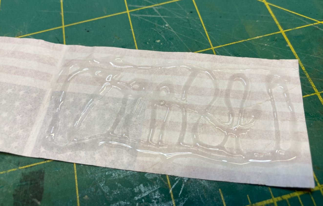
Once the two halves were glued together, I pressed them together with a steel block to smooth it out even more.
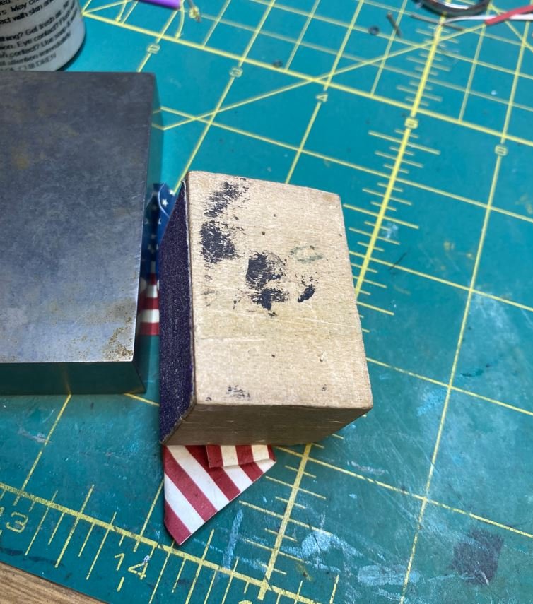
Now to the fun part. Trying to shape the ensign so that it looks like it is hanging naturally. I didn't want to show it like it was flying in a stiff wind, I wanted to have it look like it was hanging on a nice calm day, with hardly a breeze. Just enough to show the colors, but not stick out too much. I used my steel block to hold the header flat and in place since this side would be straight when secured to the rope. I then curled the rest to form a natural hanging look.
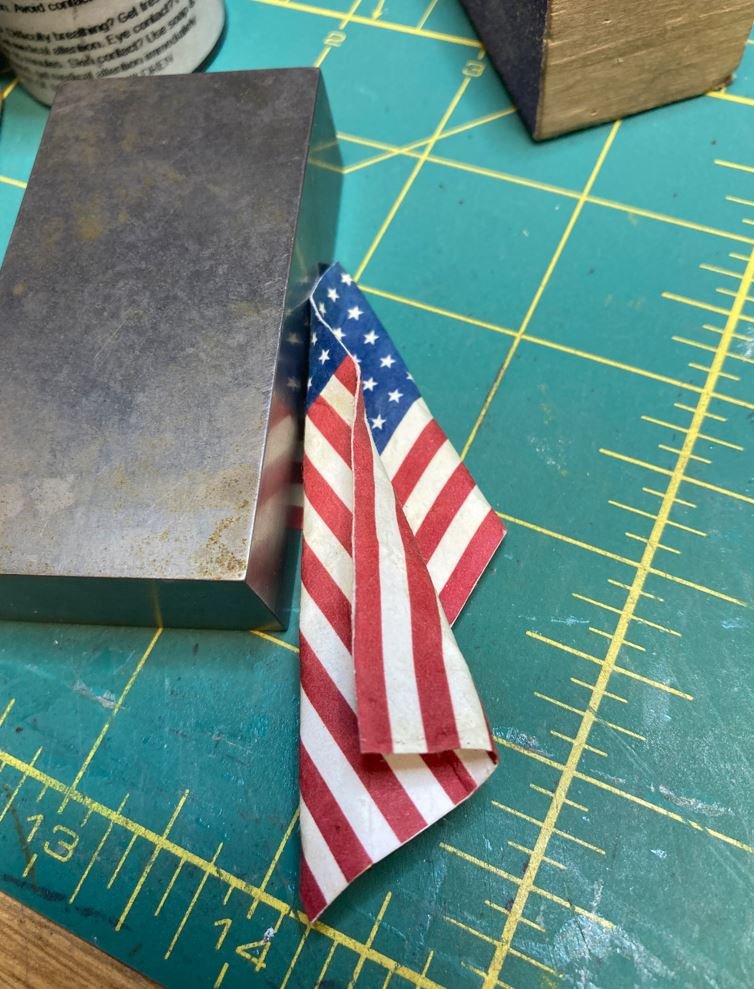
To hold the curl in position until the glue dried, I placed a wooden block on it. The block was not heavy enough to flatten the flag, but light enough to give it some dimension.
While the glue was drying, I pieced together the halyard and hooks. I simulated the grommets with a pencil and pierced the header with a small punch.
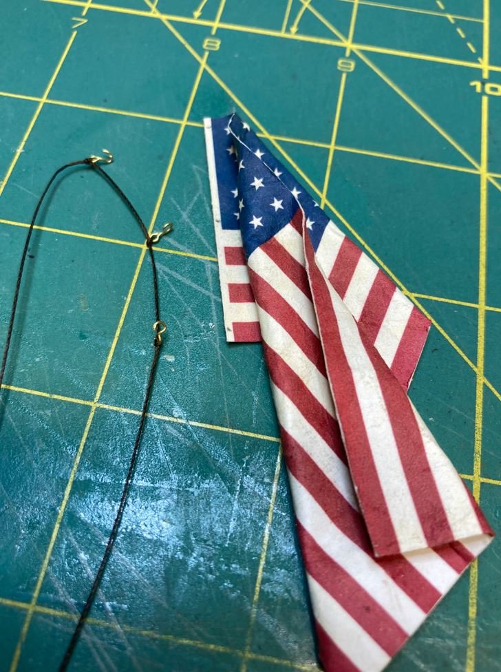
Next I needed to dress up the edges a bit so that the white paper didn't show, so I used a red and blue chalk pastel to cover it up.
I just ran the pastel softly along the edge then dusted the excess off. This seemed to work pretty good and blended the colors nicely. I also darkened the header a bit with a rust pastel to show the differences in material.
After I had the edges covered up, it was time to secure the ensign to the halyard.
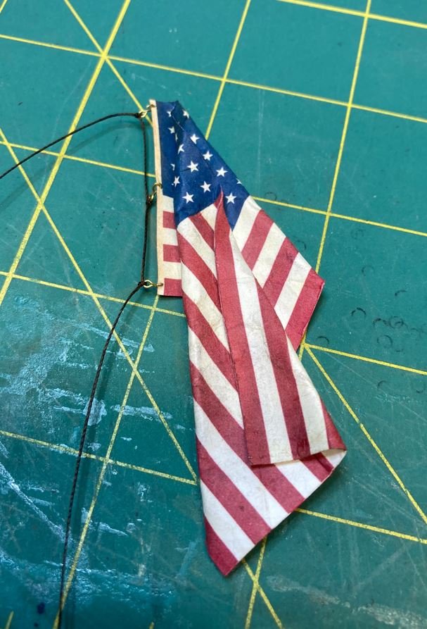
Then the whole thing was placed on the mast.
For the most part I think it came out pretty nice looking for my first attempt. I am going to play around with some other methods, but I am looking to get an opinion or thoughts on what the gallery thinks of this version. I am open to any and all suggestions or criticism. This is a learning experience for me and I'd like to make sure that I learn right.
Thanks to all for stopping by and look forward to your comments.
-Brian
-
Thank you all for the kind words and likes!
13 hours ago, bdgiantman2 said:Of all the places, to get the flag in the size suggest getting (the size of an index card), I ended up buying from a company in England!
Oh the irony of that one. 😁
12 hours ago, bdgiantman2 said:Will need to see if able to find the name of the company to send to you over private messaging.
Please, by all means send the link. I'm always on the look out for places to shop for modeling supplies. For this build I am attempting to make my own ensigns, but if I fail I may need a fallback.
There are several methods that are posted in the "Tip and Tricks" section of MSW and I want to try a few as well as experiment on my own. Most of them require the ensign to be printed out, which helps when you can't find the correct scale online, and it allows you to go with any size you like. In this case I am going with a 6'x10' 34-Star ensign in 1:48 scale. Should be just about right for the ones flown on these boats. As for the pennant, from what I have found so far, they call for them to be 32' in length. Scaled to 1:48 that is about 8" long. I think that would be a little too much and wouldn't look right on the model. I'm still investigating that one and may have to shorten it up a bit to get it to look right. I did discover that the 13-star version was used during the Civil War, so I am one step closer.
I am going to play around with these for a bit and see how they turn out.

-Brian
-
Totally impressive! I’ve just now started weathering models and see that I have a long way to go.
-Brian
- mtaylor, Egilman, popeye the sailor and 4 others
-
7
-
Hello again everyone,
I took advantage of the cold rainy weekend and got some work done on the ships boats rigging. A big thank you to @wefalck@Cathead & @Keith Black for keeping me honest and pointed in the right direction.
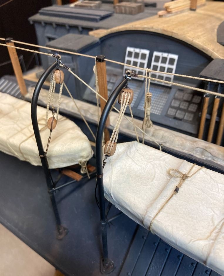
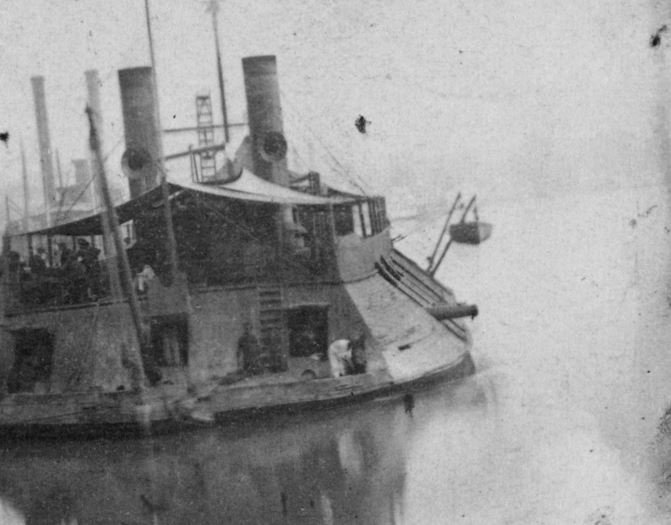
I spent some time studying the old City-Class pictures and from the limited detail the old photos provided, this is what I came up with for the control and stabilizing lines on the davits. The eyes at the end of each davit is hard to make out in the photographs so it is difficult to tell if the control lines and stabilizing lines are separate or one continuous line. I went with the executive decision to make them separate. My reasoning for this was that it would be easier to replace one shorter rope should it break than a long one, and I thought it looked better having them all separate. First thing I did was to secure the tackle to the davit on the covered boats. I did it this way out of sheer laziness, I didn't want to remove the boats and their covers and redo them with cutouts for the tackle to go down the lift rings on the boats. Not to mention that I have not been able to find a single photograph of a City-Class ship with a covered boat anywhere, to show how it was stowed.
Tackle secured to the davit.
.
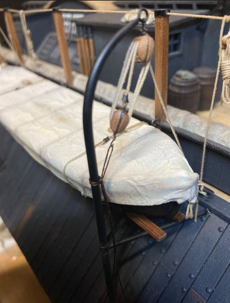
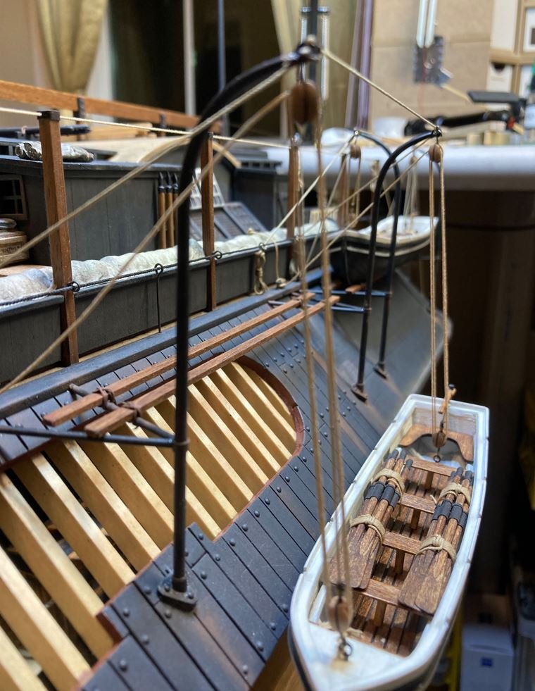
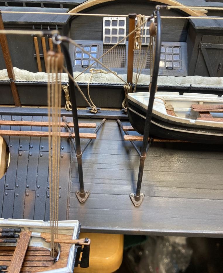
Control lines and stabilizing lines in place on the starboard boats.
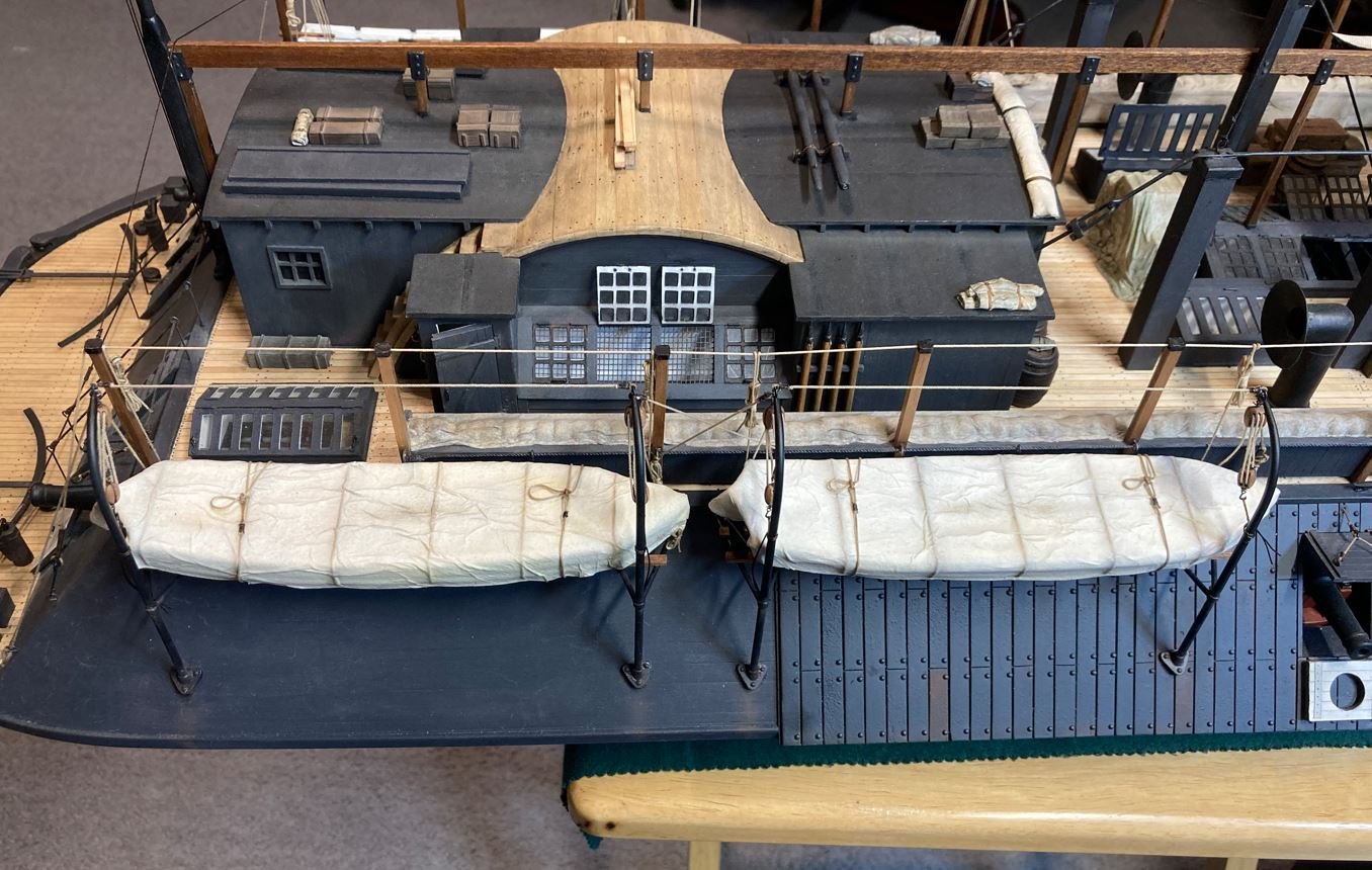
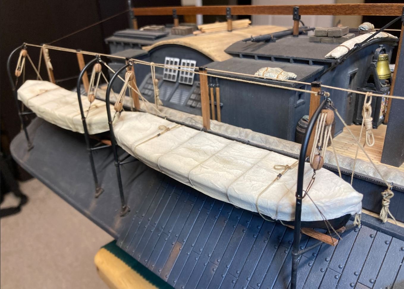
Control lines and stabilizing lines on the port boats.
Since I still had some time and it was still raining after finishing up the boats, I decided to do some touch ups and a bit more weathering. Here is some of what I got done.
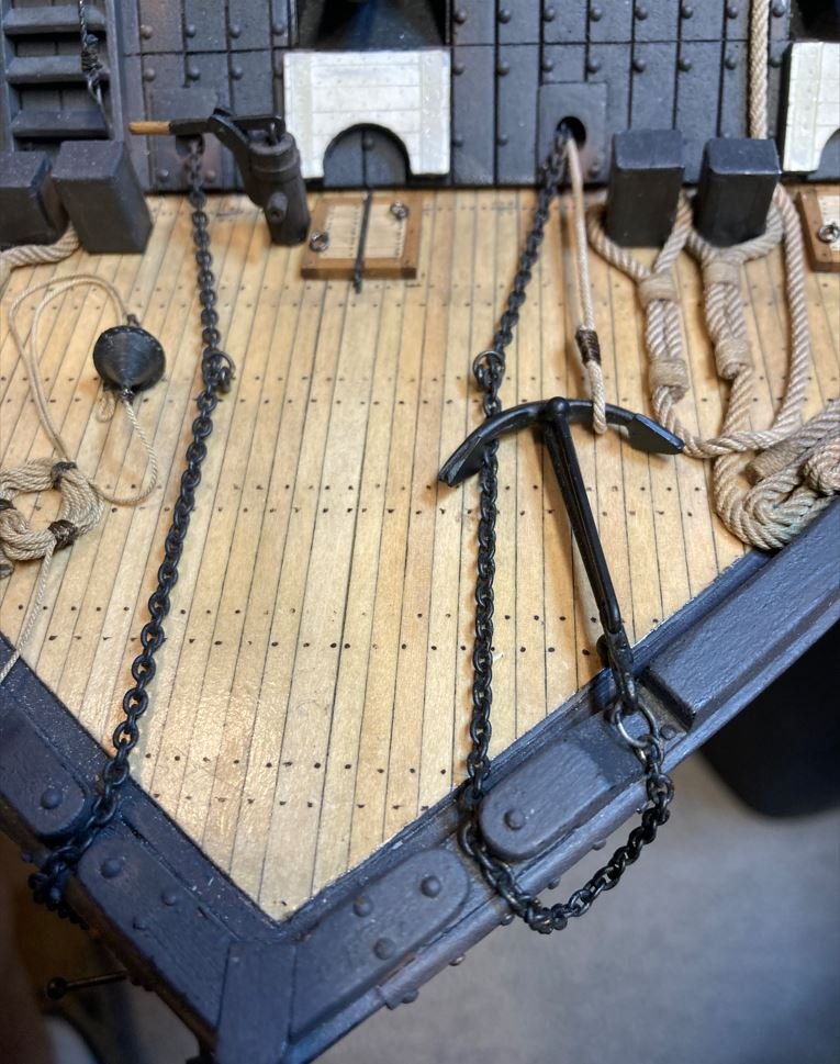
Bow weathering.
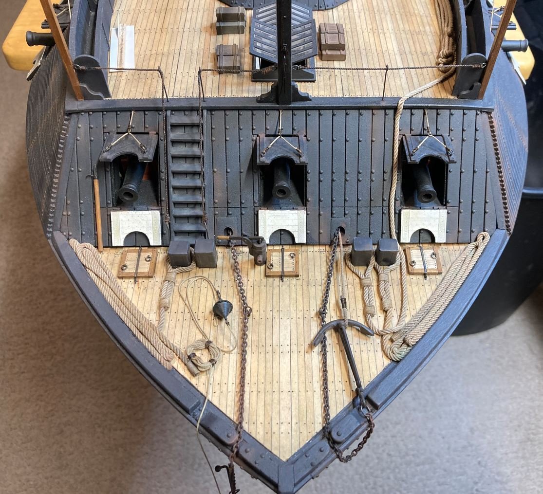
Closer details.
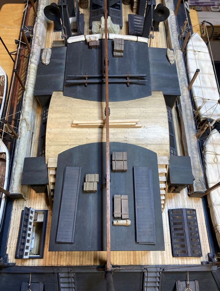
Wheelhouse and deck structure weathering.
I still have a bit more weathering to go, I just wanted to get this out there before the Thanksgiving holiday, I am currently working on more weathering, as well as the ensign and the commissioning pennant. I have seen some models and pictures of another pennant flown from the center mast on some of these ships but I am not sure of what it is. It would be a neat addition, just not sure of it's authenticity.
I also need to find out if the commissioning pennant the Cairo flew was the 13 star or the 7 star version. Still looking into that one.
Thanks again for all your input and for stopping by,
-Brian
-
-
Wow Eric! I know I am late to the party on this one. For some reason I was not getting any updates on people that I follow and I had no idea you had this log going on. I need to go in and check my settings to figure out what’s going on.
I must say that you, Mrs. Cathead and your stepfather have done a beautiful job on the outdoor kitchen, and I am extremely envious. I have the plans for one of my own (not near as fancy) it’s just getting the time to do it with all the other projects that I have lined up. So glad that our davit discussion provided some inspiration for your game hanger.
I love the Ozark’s, one of the places I miss most about living in in Arkansas. Way back when, we used to do a lot of camping and canoeing up there, but haven’t done it since moving to Texas 24 years ago. So many beautiful places to go and see.
Now that I know this is here I’ll be following along.
-Brian
-
43 minutes ago, wefalck said:
If I understand the topology of USS CAIRO correctly, than the davits would need to be turned in order to swing out the boats. You probably would need stays to steady the davits, leading from a horizontal eybolt in their tops to somewhere on the ship. There may be also a stay between the the davits, which helps to steady them in the secured position and to co-ordinate their movement, when swinging out the boats. Sometimes a number of knotted ropes werer hung from them to allow the crew to descend more easily into the boats. When the tarpaulin was on, they would be coiled and tied together.
The launching of the boats from these ironclads seems to be a bit cumbersome. Since the boats were longer than the area between the davits, the crew would have to first swing the davits forward (or aft) to clear the bow (or stern) of the respective davit. They would then pivot the cleared davit outboard and swing the boat the opposite direction to clear the second davit. Both davits would have to be rotated 180 degrees to launch the boats. I guess that's why later on some of the modifications, like this one on the Louisville, changed the davit configuration to a more efficient way of launching them.
 58 minutes ago, wefalck said:
In the first pictures of USS TENNESSEE shown above, you can see the spar (minus the bolsters) I mentioned earlier. In fact, on rigged ships, these spars may have doubled as reserve-spars.
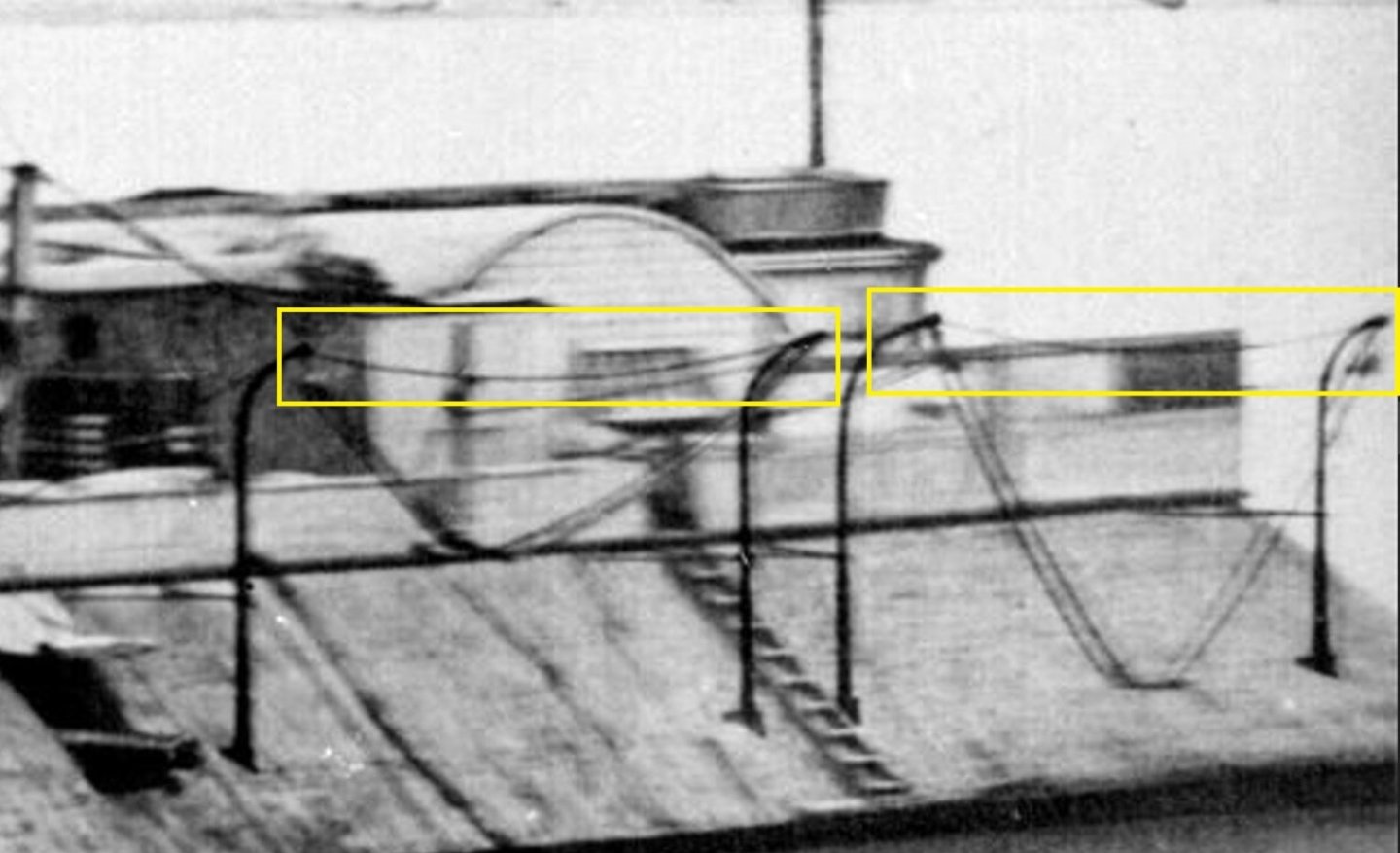
I now understand what you were referring to with this. Took me a bit, but I think I got it. I went back and looked at some of the photos and found this on the St. Louis. It looks like there were ropes that ran between the rings at the tops of the davits that kept them at a uniform distance, They also could have been used to control the swing of the davit when rotating them inboard and outboard. I'll need to go back and revisit this and see what I can dig up. It might be a worthy addition that I missed.
-Brian
- mtaylor, Keith Black, Cathead and 1 other
-
4
-
3 hours ago, wefalck said:
Sometimes davits or anchor-cranes had a ringbolt in them or they stropped a rope with an eye-splice around them into which the hook was hooked and the tackle set taught - on a well-kept ship nothing dangles or bangs.
The ring reaching up through the tarpaulin was not my idea, but it was common practice as one can see on old photographs. The tarpaulin had to slots reaching half-way across the boat so that you could remove it wihout having to unhook the tackles (which would have been impossible anyway with the boat hanging on them). The slots were closed with an overlapping piece and laced up like a boot.
There is also no interest in keeping the boat completely dry. To the contrary, every now and than a couple of buckets of water were spread in them to keep the wood humid, otherwise it would shrink and the seams would open, making it leaking initially while in use. The tarpaulin was just there to keep dirt and excessive salt out and the equipment in or protected.
Eberhard, apologies for the redundancy. I didn't refresh my screen before I submitted my last post and didn't see this reply. I think that the eye-splice around the davit itself would be the perfect method to store the loose tackle and one that I am considering going back in and installing. This will allow the tackle to be stowed neatly and keep me from having to redo my boat tarps. More to come on this shortly.
3 hours ago, Lieste said:With the fluke biting in the bottom, and the cable running along the bottom, the initial pull of the cable when weighing anchor will tend to dig the flukes deeper, and if the bottom is shallow there may not be enough angle put on the hank to pull the flukes clear over a wide enough 'spread' to be able to hold that station. If instead of trying to solely pull the anchor from the hank, you trip the crown, the flukes come clear of the bottom, when intended and the anchor can be weighed more easily.
Lieste, thank you for the insight into anchor operations. I had no idea that there was so much involved with setting them. I thought the anchor was dropped overboard and once it hit the bottom, the wind or the current would set the fluke into the bottom and hold the ship in place. This is just going off my limited knowledge of small craft when I go fishing. Toss the anchor overboard and hope it hooks on something to hold me in place, then pray it doesn't get snagged on a submerged stump or something.
2 hours ago, Keith Black said:Brian, what a amazing build holding true to the original Cairo.
On the Tennessee, how the ships boats were held in the davits seems to have been weather dependent.
When the weather was fair the ships boats were uncovered and held with block and tackle. When the weather was foul the ships boats were covered and held with canvas straps.
Thank you Keith for the kind words and the examples. When I started this build I had just intended to show all the boats covered like many of the models of the Cairo I had seen. As I progressed through the build and really got into the details of the boat, l decided that I wanted to show the boats in different stages of launch and storage. One of the things that I had not thought of as I was building them was how would they be stowed if they were covered and none of the models out there have that much detail in them. I was studying the pictures that you posted and realized that there is really a lot more to it. While the davit operation on the Tennessee was a bit different than the Cairo, I would think that the stowed methods would be similar. This would probably explain why almost all photographs of the City-Class ironclads show the boats uncovered, because the weather was good when the picture was taken. It was either that, or they never did cover any of the boats to begin with (but I doubt that).😁
-Brian
-
5 hours ago, wefalck said:
There may have been some sort of long chain-link penetrating the tarpaulin covering the boat.
Eberhard, I had considered that method of of just running the tackle through the tarp and securing it to the rings, but the more I thought of it it seemed like a not very efficient way of launching the boats. The crew would have to unhook the tackle, to remove the tarp, then reinstall the tackle to maneuver the boats into launch position. Of course, I didn't take into consideration that the tarp could have been split and tied around the tackle at the penetration point and this could have quickly been unlaced and the tarp removed. Looks like there are several possibilities that I hadn't considered. Thank you so much for the input.
3 hours ago, Cathead said:One quick thought on the tackles: for processing deer and other livestock, I use a singletree hooked to a block & tackle that allows me to raise and lower the animal easily. During deer season I leave this hanging so it's ready to use. However, I find that wind easily whips the tackle around and tangles it, creating an annoying task that I never get to until there's a carcass waiting below. These ironclads may never have encountered rough seas, but they sure as heck encountered high and whipping winds, and I'd suspect those tackles would get badly whipped around and tangled if left hanging like that. It's possible that could even cause damage; imagine a wooden block repeatedly slamming against an iron pole in gusty winds. And I think even a brown-water Navy vessel would want those boats quickly deployable.
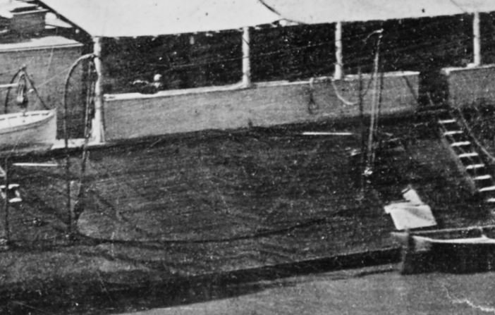
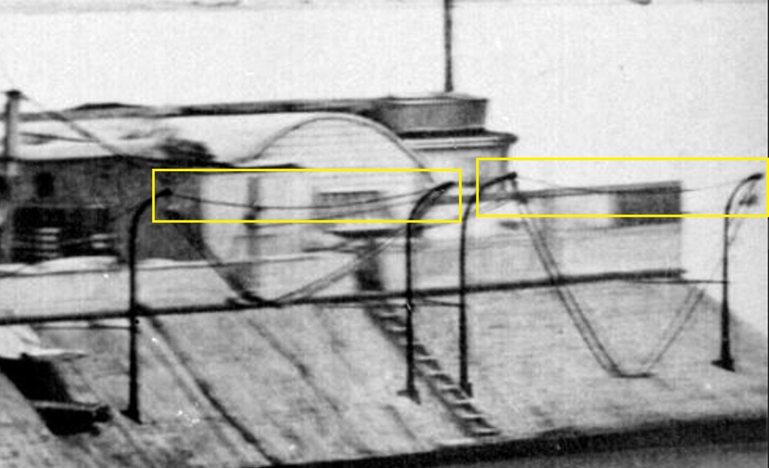
Eric, that is a great analogy, and something I had not considered was the wind swinging the tackle around. I forget that the winds along the rivers could get a bit gusty and when storms hit, it only makes it worse. Several of the contemporary photos show the empty davits with the tackle hooked together at the bottom block and others show it secured to the bottom of the davit mounts like the two examples below. My dilemma is that I am not able to find any good photographs of the City-Class boats with their boats covered and stowed. I do agree that the tackle should be secured to prevent this from happening. It definitely helps to talk things out and get input on other possibilities. I tend to get tunnel vision at times when I am focused on a project and forget that there are other avenues to consider. I think I am going back to revisit the tackle and see if I can come up with a better method of stowing the loose tackle.
Tackle on the Cincinnati secured to the davit base.
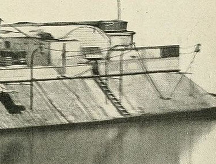
Tackle on the St. Louis hooked together and hanging.
-Brian
- Cathead, Keith Black, FriedClams and 2 others
-
5


USS Cairo 1862 by MPB521 – FINISHED - Scale 1:48 - American Civil War Ironclad - First Scratch Build
in - Build logs for subjects built 1851 - 1900
Posted
I have a set of diamond needle files that work great for fine sanding wood in those hard to reach places, but have never used one on a saw. Seems that the speed factor would tend to gall up the blade pretty quick with the wood fibers.
-Brian.