


mbp521
-
Posts
989 -
Joined
-
Last visited
Content Type
Profiles
Forums
Gallery
Events
Posts posted by mbp521
-
-
Hello again Everyone,
I just realized that it has been a while since I posted a proper update on the Cairo build. Well, hopefully I don't disappoint too much because not a lot has been done. The nice cooler weather has kept me outside taking care of those much needed projects that were not possible in the summer heat, but I am ever so slowly creeping towards the finish line on this project.
Here is what I was able to get done over the past month or so.
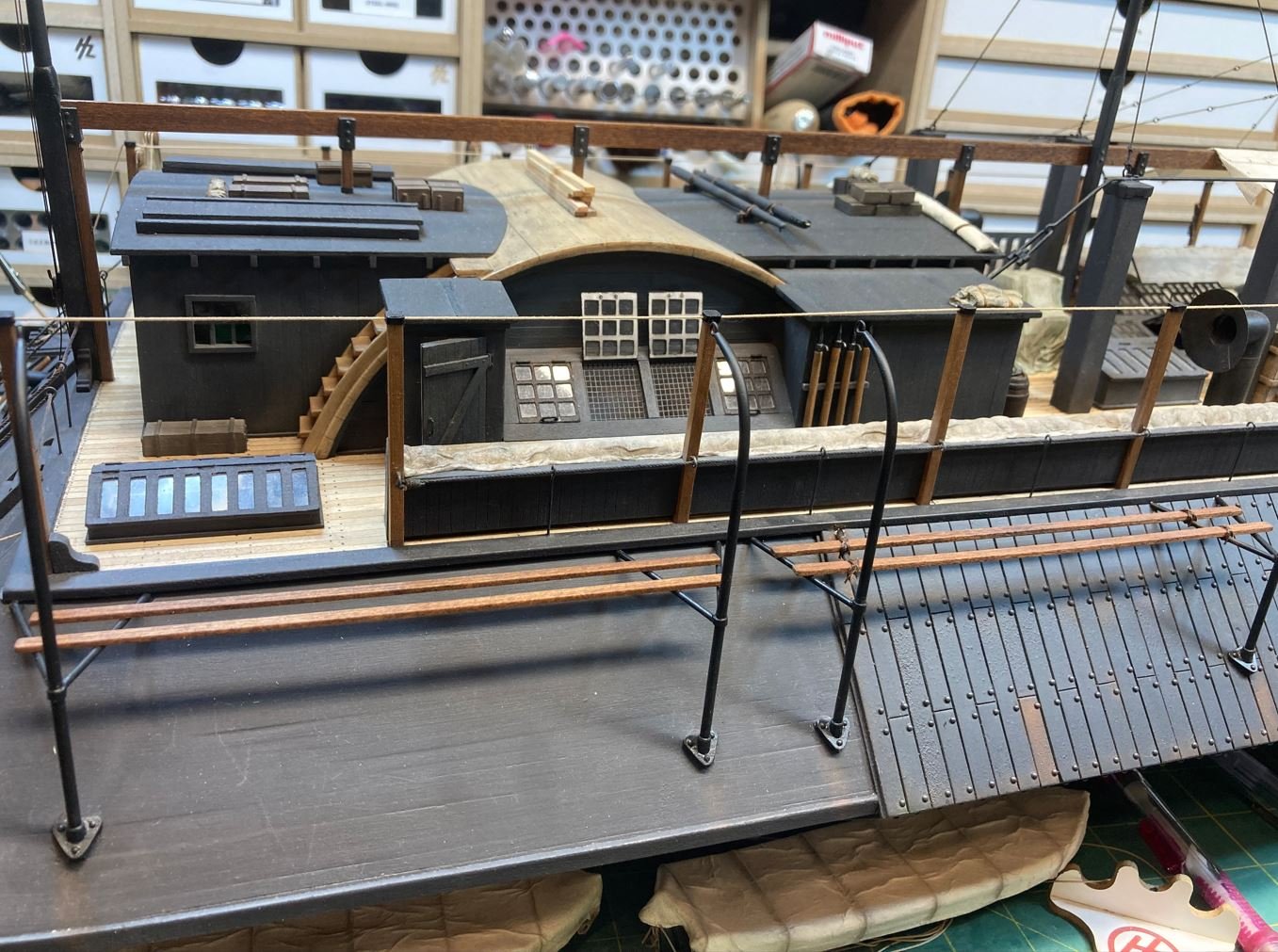
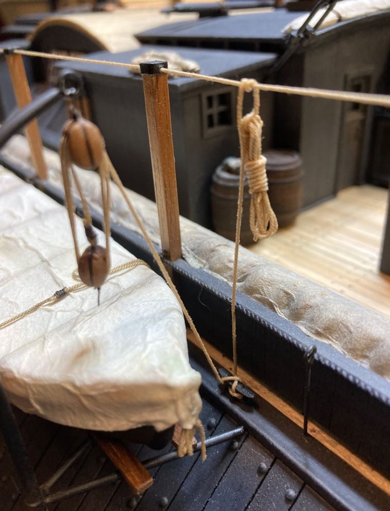
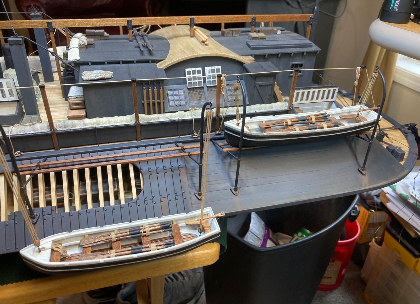
First up was the completion of mounting the ships boats and getting them rigged up, As usual, information on the City-Class boats was very limited and I resorted to using a few builders liberties on this part. The sloped sides of the casements made for a somewhat unique way of storing the ships boats. The davit bases were mounted about 3/4 of the way down the casements and the middle of them was supported by horizontal bars attached to the casements just below the Hurricane deck. These middle supports served multiple purposes, center support for the davit, provided a swivel point of the davit to launch the boats and a resting place for the boats themselves when stowed aboard. While I was trying to find out how the boats sat on the davit supports I was playing around with the configuration and got to thinking that if these boats were to just sit on top of the davit supports, there was no stability for the boats to just sit on their keels. So I researched and researched some more, and came up empty. So I decided to take my builders liberties and install a couple of planks lashed to the supports to run parallel to the boats keels and give them more stability. My thoughts on this were that not only would the planks add stability to the boats by keeping them level while stowed, they would also add some protection to the keel keeping it up off the iron supports. It sounded logical to me so this is what I went with.
Here are the planks installed and lashed to the horizontal davit supports.
Next up was to get the tackle rigged up. I diluted the ropes with 50/50 water and clear Elmer's glue solution to stiffen them since the boats were not heavy enough to keep the lines taught enough to look natural.
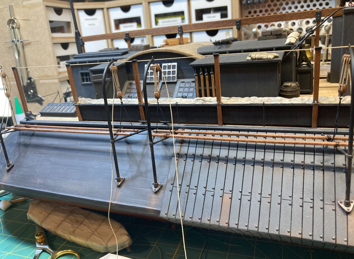
Another configuration that I was having some difficulty finding information on was how the boats were stored when covered. The lifting rings were not accessible with the tarps over them so it wasn't possible to have them attached to the blocks without cutting holes in the covers. So again I decided that when the boats were stowed and covered the tackle was just left hanging loose above the boats. I don't think there would have been too much concern of the tackle swinging around in rough seas, since the rivers were considerably tamer than the open ocean. When the crew was ready to launch the boats, the would simply remove the tarps, hook the tackle to the lift rings and launch the boats. Problem solved.
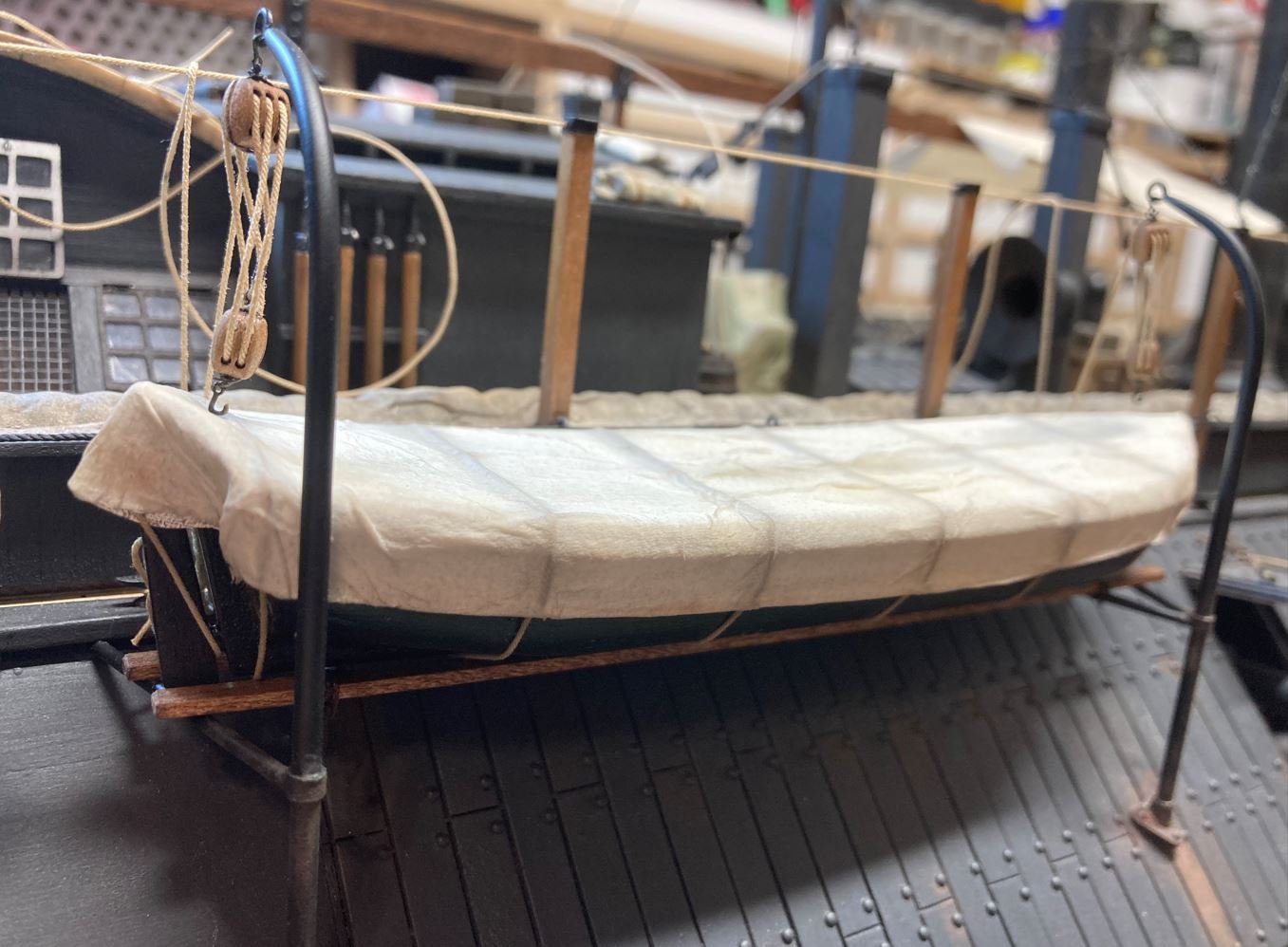
Completion of the rigging. The ropes were tied off to cleats mounted to the Hurricane deck and the leftover was coiled up and thrown over the ropes running through the tops of the stanchions. This method is seen in many of the contemporary photos of the City-Class boats.
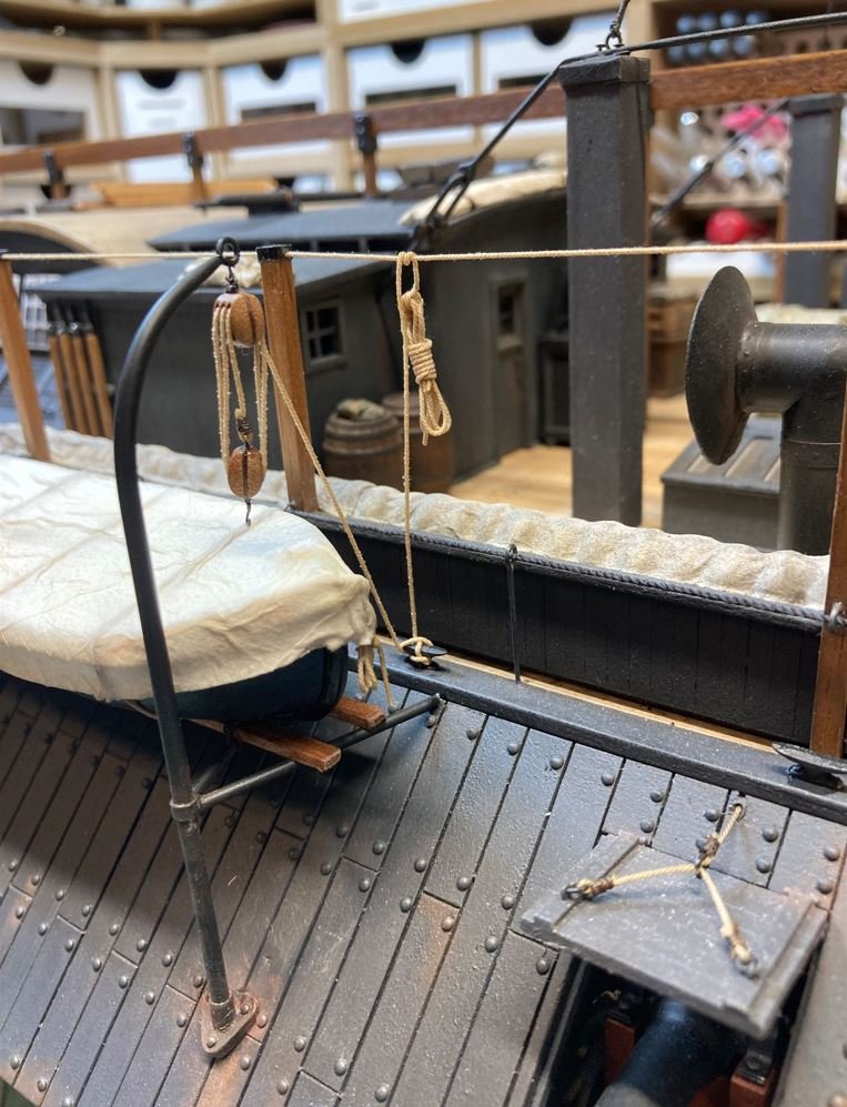
Closeup of the rig. I also added some ropes to secure the boats in their cradles. These were just wrapped around the boats and the planks just to help keep them in place.
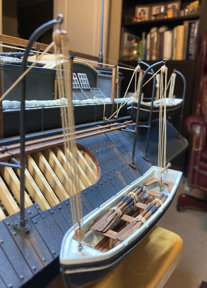
The port side boats were a little easier. The aft boat I mounted in the ready for launch position and the forward one was mounted at the waterline, as if ready to head to shore. Having the forward boat in this position also allowed the viewer to peek inside the cutaway in this area.
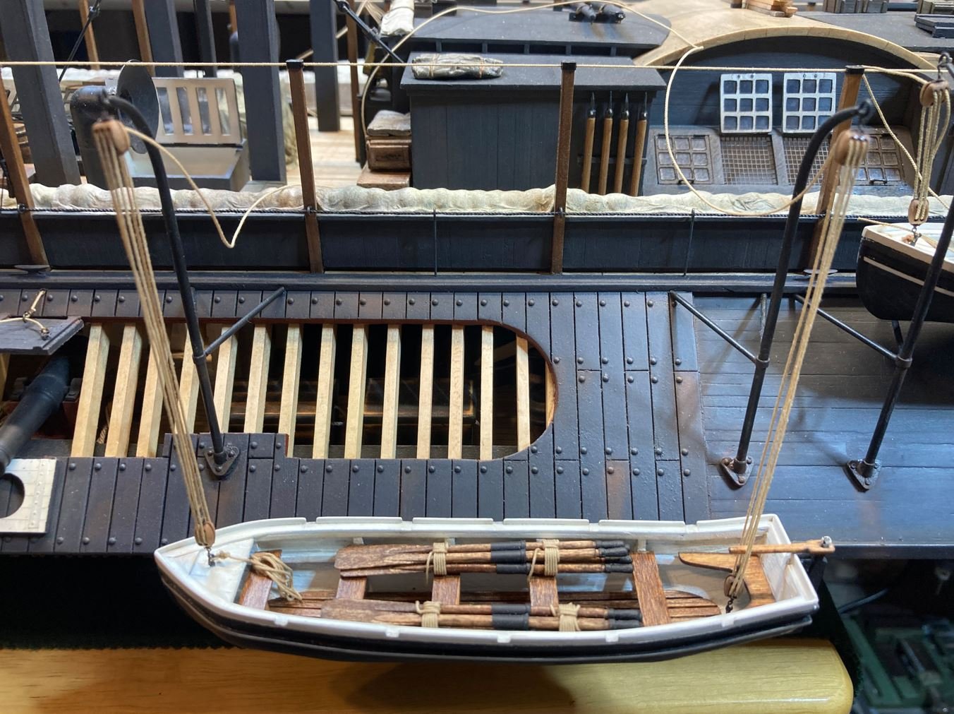
Same rigging method was used as the starboard boats. The ropes were stiffened with diluted Elmer's to give them a "natural" hang and then secured to cleats, only this time the leftover rope was thrown over the hammock nets.
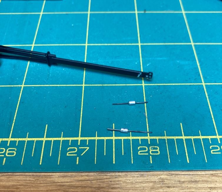
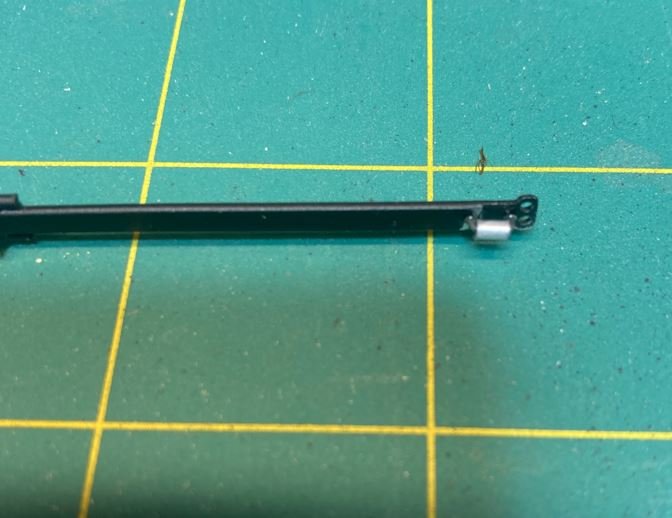
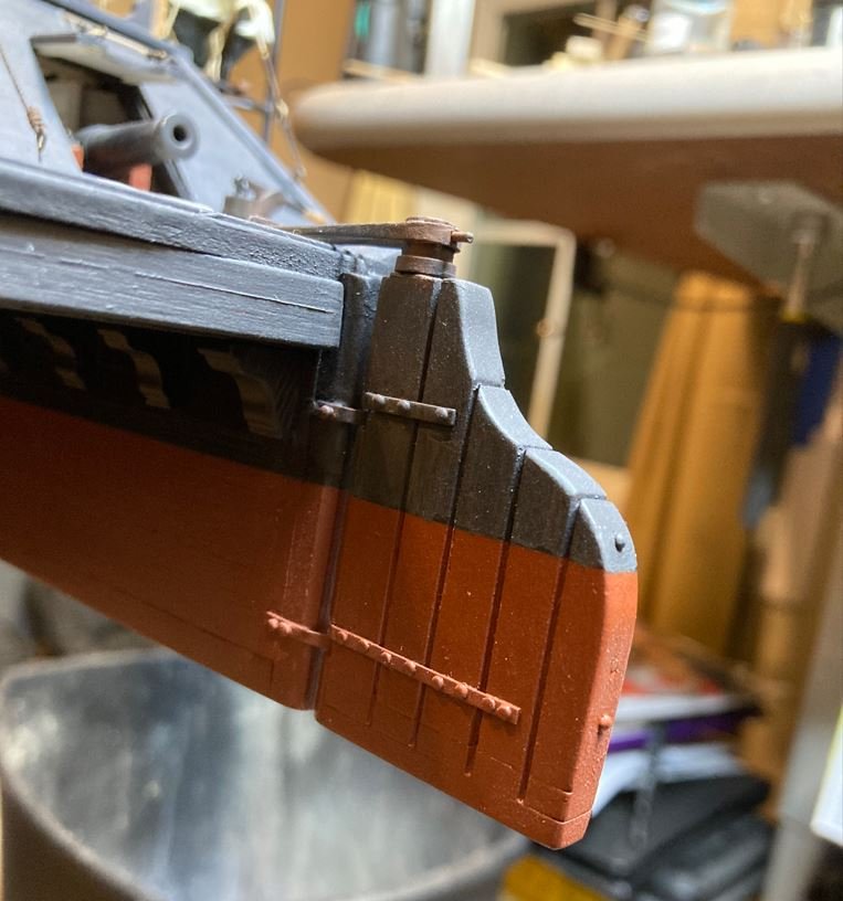
Next up it was time to finally install the rudders. I started out by installing the rollers on the tiller. These were made from small aluminum tubing and 28ga wire. These rollers sat on top of the races mounted to the fantail deck and provided support for the extremely long rudder tillers and followed the tiller arc when the ships wheel was turned.
Rudders being set into place on the hull.
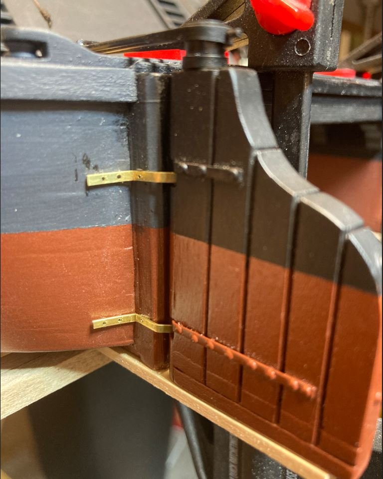
Port rudder installed.
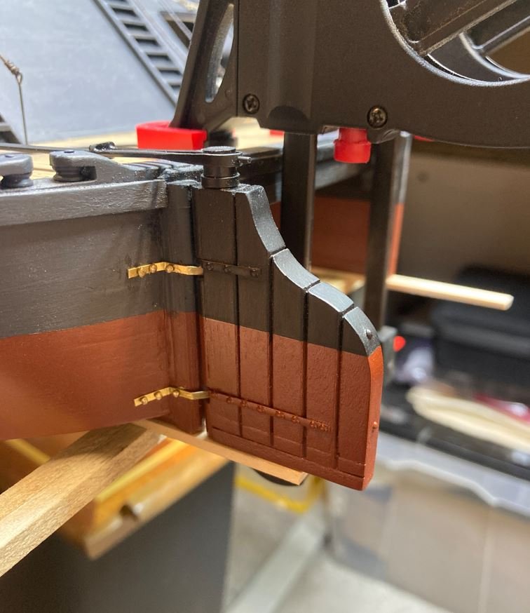
Final paining of the rudder hardware.
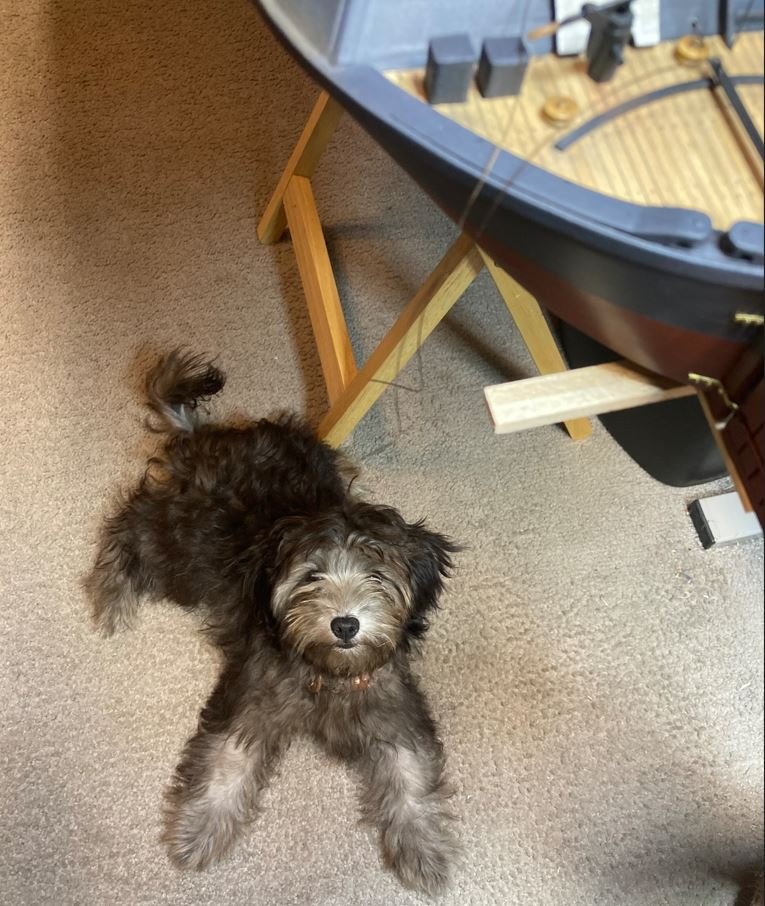
Our newest crew member Daisy, the Admirals six-month old Yorkie-poo. She paid me a visit to make sure that things were going as they should. Thankfully I passed inspection.
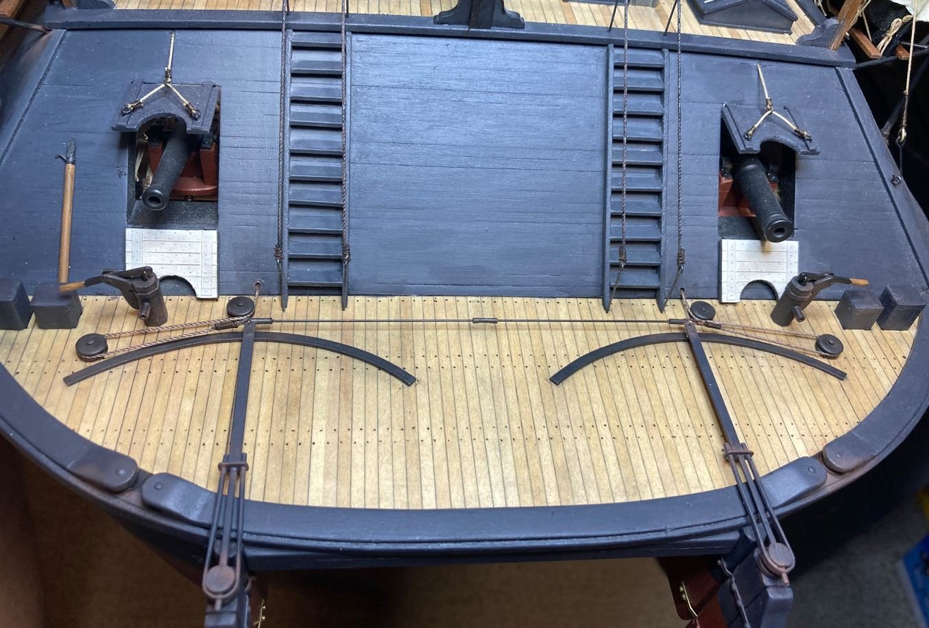
Once I had the rudders installed it was time to get the control lines added. This was another of those details that there was practically no information on so I went with some of the suggestions of those following along and what I though would the most logical approach to how these control lines would have been done. Salvage photos of the Cairo show a few clear pictures of the recovered rudders as well as some scenes in the recovery video. All of them show nothing attached to the outboard side of the tillers and what either appears to be stiff wire cable or an iron rod mounted to the inboard sides of the tiller. Since there was nothing shown on the outboard sides, I made the executive decision that since this was the side that was attached to the ships wheel, this control line must have been made from hemp rope and would have rotted away over time, leaving no evidence. If it would have been chain or cable, there would have been some sort of remaining evidence of such material or connection. As for the intermediate linkage, I went ahead used the suggestion that this would have been an iron rod with a yoke on each end that attached to the tiller and a turnbuckle in the middle to make steering adjustments as needed.
So here is what I came up with. The intermediate linkage and control rod. Again, I used small aluminum tubing for the yokes and turnbuckle.
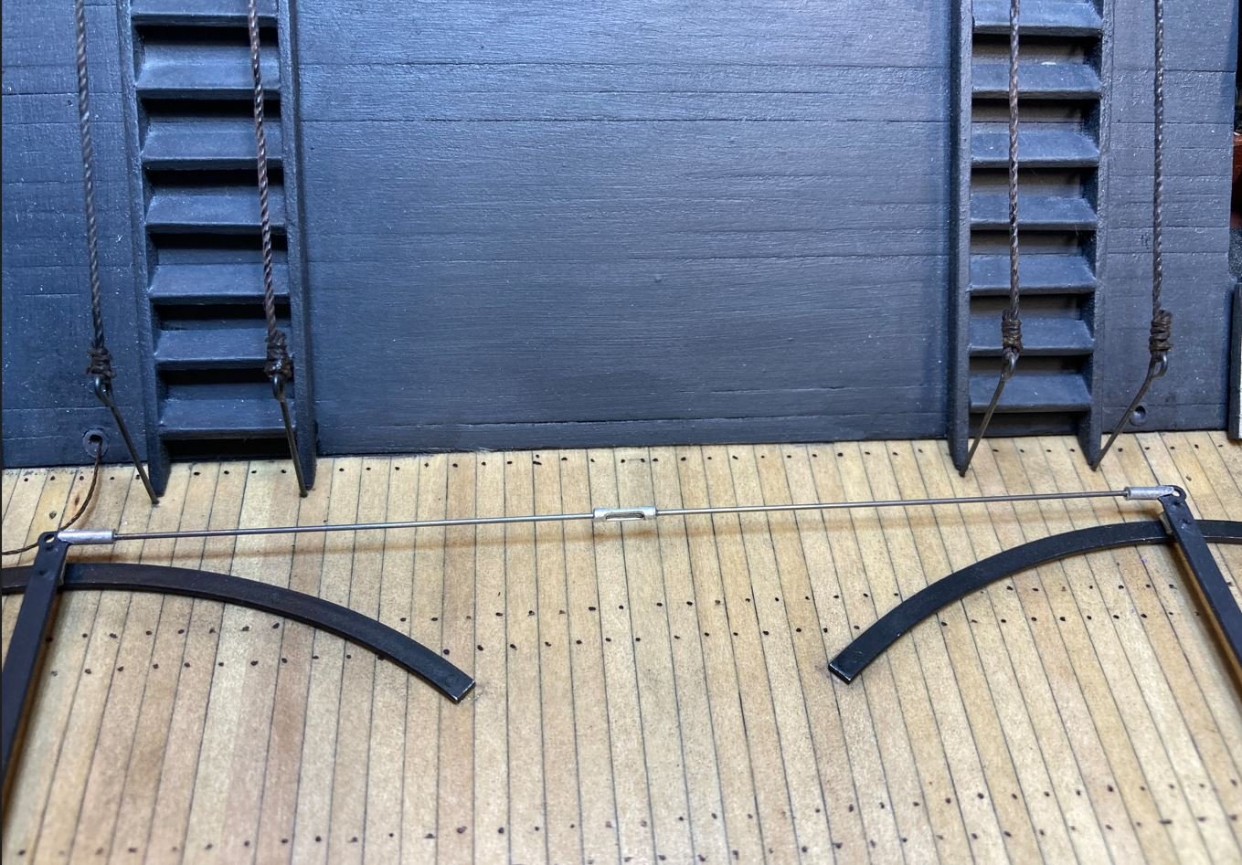
Then the control lines were made from rope and secured to the outboard sides of the tiller. The pullies were made from spare deadeyes that were covered to conceal the three holes in them. All in all, I am completely satisfied with the way this turned out.
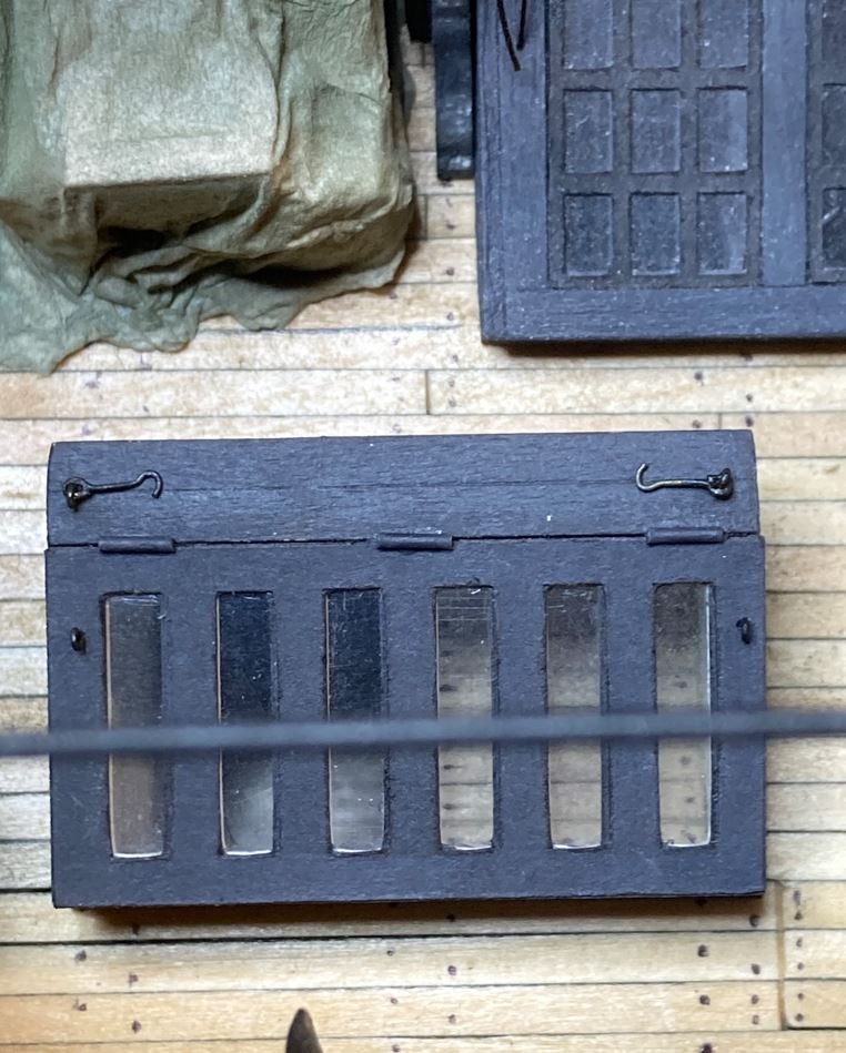
The last little detail that I was able to get completed this time around were the latches for the skylights. There is no photographic evidence of these latches, but there were several recovered from the wreck that are on display in the museum. I took a stab at where these would have been used, but logically thinking, something had to hold these skylights in the open position.
Starboard aft skylight with latches installed.
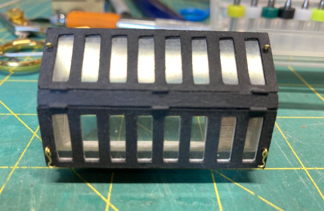
Painted and installed.
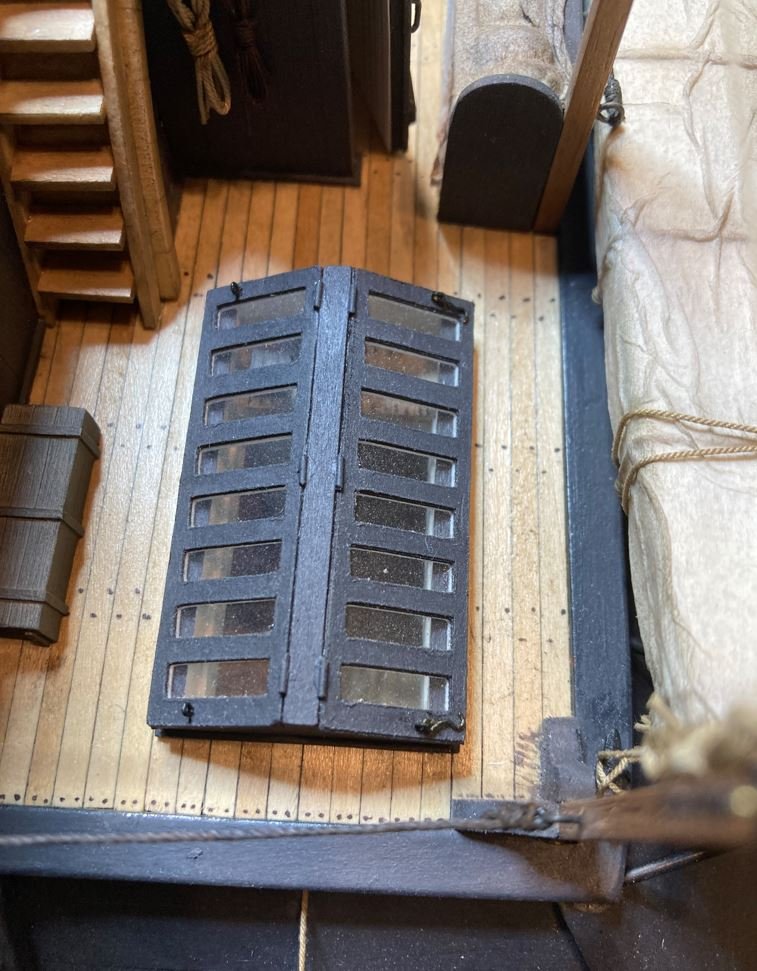
Port skylight in the open position with the latches installed.
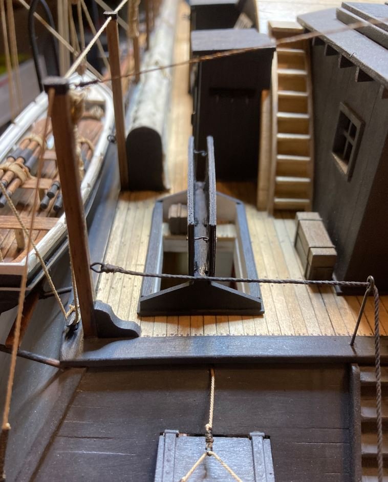
Port midship skylight in the open position showing the latches holding the hatch open.
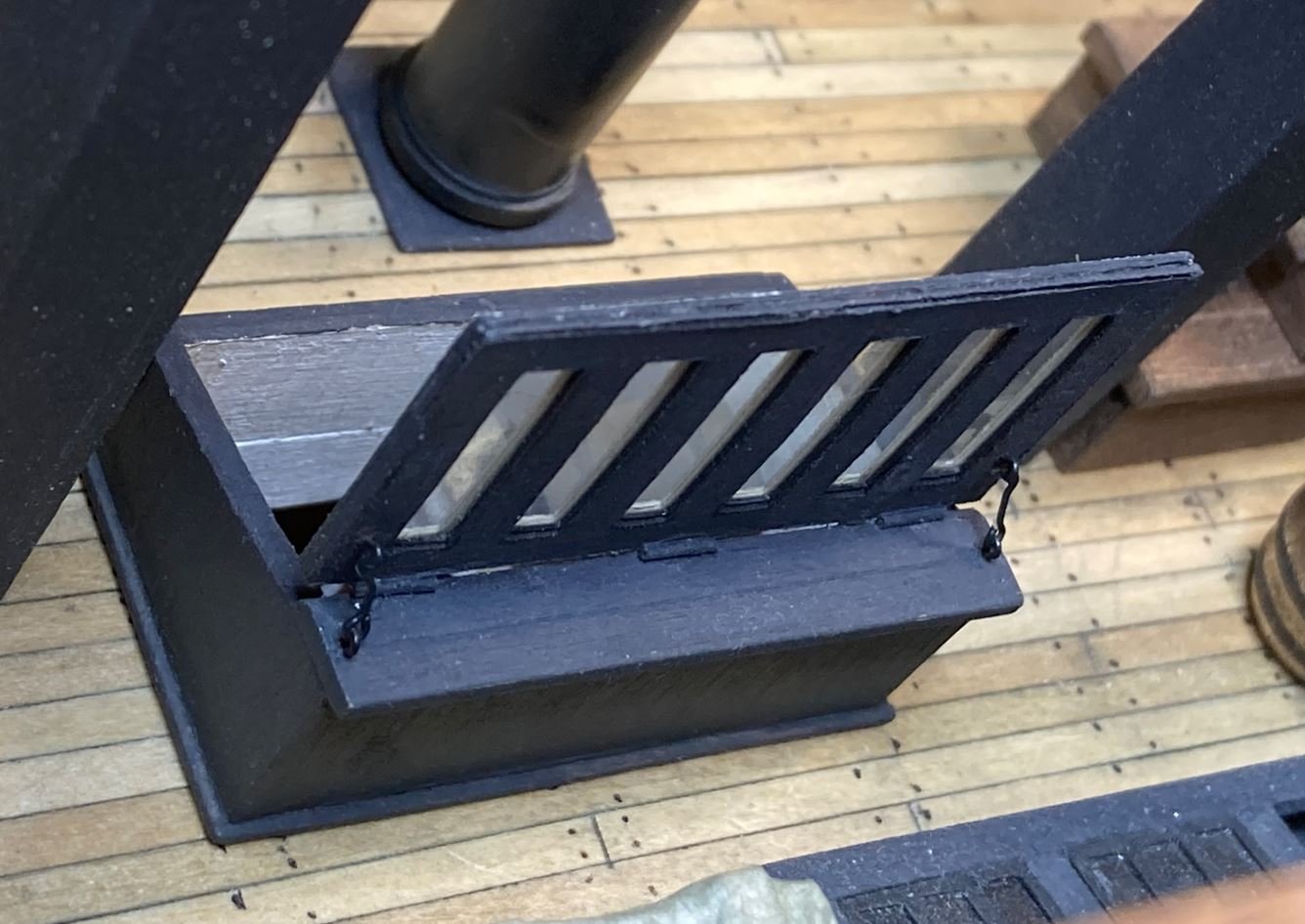
Starboard midship hatch in the closed position.
Well that is all I have for this update. December 12th is fast approaching and my checklist of things to finish is getting shorter. Most of them are small details that are really not photograph worthy (paint touch-ups and weathering), but I'll take pictures of anything that would be of interest. I need to research what the forward pennant looked like (many of the contemporary photographs show these boats flying one, but unfortunately they are all blurry). Once I find the correct one, I'll get it printed out and installed as well as the 34-star Ensign. I have read several methods on MSW as to how to make realistic looking flags, I am going to experiment with a few of them and see which one I like best.
Until next time, thank you all for the encouragement, kind words and likes and for just stopping by and taking a look at my build. Stay safe and healthy.
-Brian
-
Keith, I can’t think of anything else that hasn’t been said already. So at the sake of sounding repetitive, WOW! Beautiful work on the rope coils. I’ll definitely be sad to see this build end.
-Brian
- Keith Black, FriedClams, mtaylor and 1 other
-
 4
4
-
30 minutes ago, John Gummersall said:
I am going to rack it up as variations in the wood.
I seem to recall having a difficult time with everything lining up in this area as well. Not sure if the holes in the deck were off or piece 37B was not cut properly. Either way you seem to have overcome that obstacle very nicely.
As for your cleats, I’m not a big fan of any of the Brittania fittings that MS puts in their kits. If one takes the time to clean them up they can somewhat make them look presentable (which I did in this case), but normally I just chuck them and go with upgraded brass or wood fittings. If you are looking for suggestions or opinions for yours, I would go ahead and paint them either black or white as they would have been on the actual boat.
Speaking of tricky alignment, the boiler covers and boiler deck were another one of those. While lining them up with the forward staircase, you also have to watch the back side where it lines up with the aft walls of the engine room.
Beautiful work so far. Looking forward to more updates.
-Brian
-
I sit here in awe and think, how can this build get any better. Some how you keep showing me. Simply beautiful Keith!
- Brian
- Keith Black, Retired guy, KeithAug and 3 others
-
6
-
-
46 minutes ago, John Gummersall said:
IF that is the case, then I am defiantly not a professional modeler.
I guess I’m not one either. 😁 I just glued mine in place and they held just fine, as long as you don’t put too much strain on the rigging line.
Very nice work on the stairs. I also like the added walls for the front of the machine room, they should cover the opening fairly well. You do have to be looking for it once the boiler deck, boiler and other features are added, but the opening can be seen.
-Brian
-
This jolly boat just keeps getting better and better. It almost would warrant a build log for itself. Beautiful detail Eberhard.
-Brian
- shipman, mtaylor, Keith Black and 1 other
-
4
-
I am at a loss for words. For only having a few sheets on this boat there is an insane amount of rigging. Beautifully done.
-Brian
- mtaylor, Retired guy, KeithAug and 1 other
-
4
-
Just amazing work. I still have a hard time believing that you are using paper for this.
-Brian
- mtaylor, Keith Black, Ras Ambrioso and 1 other
-
4
-
-
On 10/16/2022 at 4:44 PM, John Gummersall said:
Purest will roll their eyes on this, but to me it makes a lot for sense to bend two 1/32" x 1/8" strips instead of one 1/16" x 1/8" strip. After soaking them, they bend ready easy and at my skill level will save me a lot of headaches.
It’s all about getting it done. It’s not really fudging if the look is the same. That’s actually the way that I did it after a couple of attempts to bend the thicker material.
-Brian
-
Looking good John!
I do agree that those stairs are a bit tricky, no matter how easy they may look. But as you said, they are still nothing compared to the round ones on the King of the Mississippi.
8 hours ago, John Gummersall said:I thought it would make them look a little more realistic, but after you paint them, not sure that was necessary.
Unless you just pour the paint on, you’ll be surprised as to how much of the individual planks show through adding that touch of realism.
If I may throw a suggestion out there, if you don’t plan on permanently mounting the hull to the base until you are finished with the model, I’d leave the rudders off until the very end. They tend to snag on everything when moving it around. It will also help to get them aligned when you install the paddlewheel and get the clearance right.
-Brian
-
I’ll echo Mark’s comments. Life always takes priority. I’m in the same boat (pun intended), lots of work around the property that needs to be done with the cooler weather, so shipbuilding takes a back seat. Whenever you get back to the bench, we’ll be here to cheer you on.
-Brian
- Keith Black, mtaylor and Cathead
-
3
-
Just catching up on your build. You are moving right along with this.
I am a little curious though, do the kit instructions call for the third cannon on the aft casement? Contemporary photos and the recovered wreck have only two cannons mounted on the aft of the boat on the port and starboard sides (a 30# Parrot and 32# smooth bore respectively). In the center aft over the water way was the captains cabin. It looks as thought the kit came equipped with 14 cannons, which would be correct if it is to have the 12lb howitzer on the Hurricane deck.
15 hours ago, rcmdrvr said:I could not find where the plans showed the location of the doors and windows but by looking at a few pictures on the internet and in the instruction booklet; I think I found the proper locations.
You nailed it. There are numerous photos of the Cairo's sister ships out there, many of them show the wheel house structure with the doors and windows in different areas, of course this could be due to modifications or repairs over time. However, according to the only photograph of the Cairo, this was where the doors and windows were located.
-Brian
-
Eberhard, I have to go along with the previous comments from Keith, Druxey and Thomas. At that small of scale, unless you are using a magnifying glass and closely inspecting the hulls, its not noticeable at all. You have all my respect. With my big hands there is no way that I could even come close to the quality of workmanship you produce on such tiny boats. I would have just drawn the individual planks on and called it good. 😁
-Brian
- shipman, mtaylor and Keith Black
-
3
-
On 10/1/2022 at 12:35 PM, KeithAug said:
The anchor looks great Brian. Over here we would call the rope attached to the crown a "tripping line".
Thank you Keith. In pouring over all of the contemporary photos of these boats, I found that the outside decks were really quite busy, with plenty of tripping hazards. Especially the fore deck and fantail. I would venture to say that more than one sailor ended up in the water due to not paying attention to all of the ropes laying about. I've been on many museum ships and noticed that things were always stored away and tidy. Not having served in the Navy, I'm not sure if this is the way things were all the time on active ships, especially during wartime. Given the nature of the military, I would assume so. But, due to the limited number of photographs of the City Class Ironclads, they all seem to have a certain bit of clutter on the exposed decks so it's hard to tell if they kept the same standards at the time.
On 10/1/2022 at 1:39 PM, vaddoc said:Just caught up with your log Brian, what a fantastic model! But your log is by itself so very interesting. A moment in history that many of us across the pond were not aware of.
I appreciate the kind words. I was hoping to make the build log as interesting as possible. The American Civil War is a dark time in American history, four years of brother against brother fighting. Growing up in south Louisiana (Baton Rouge) I was surrounded by plenty of reminders of this dark time. As a kid I was somewhat jaded to the fact that the South should have won and was resentful of the North for having done so. However, as I got older (and grew a brain) and studied more on the history of what transpired during that time, I realized that the Union was fighting to keep this country together. History has shown over time that countries that fight for separation from themselves, doesn't always work out like planned. Thankfully the US was able to stay together. No telling what things could have been like if the end result was different.
19 hours ago, archjofo said:almost finished !
This has become a wonderful model.
A lot of beautiful detail finishes.
Maybe you'll make it to the 160th anniversary after all.Thank you so much Johann. I still have a bit to go. I spent a few hours the other day creating a punch list of things that need to be finished. As it stands right now I have at least a couple of months worth of work to do. Lots of small details and touchup work. Also, with the weather finally starting to cool off here, more outside projects are taking priority which takes away from the build time. I am trying my hardest to get it done by December, but I'm not going to rush it. Either way, I will have small celebration on December 12 to commemorate the anniversary.
-Brian
- Cathead, Roger Pellett, mtaylor and 5 others
-
8
-
-
That is a huge difference in the shape of the parts. I can now see why you were having trouble sorting out the lines. Glad to see that Blue Jacket was “Johnny on the Spot” with getting the error corrected. Nic and his crew are always a pleasure to deal with.
-Brian
- mtaylor, Cathead, Keith Black and 1 other
-
4
-
-
What a beast! I knew this was a big build, but seeing it sitting on the Workmate just gives a better scale to it. Totally impressive!
-Brian
- Retired guy, KeithAug and Keith Black
-
3
-
Beautiful job on the rigging Tom. These cross sections are much easier to rig up than the full ship. Not near as many snag points.
-Brian
-
So much detail in such a tiny space. I do love the technique for getting the form of the boats. I will definitely have to give that method a try in the future.
-Brian
- Keith Black, bruce d and mtaylor
-
3
-
Thanks for posting these Tim. Looking forward to seeing more.
-Brian
- mtaylor, Keith Black and Canute
-
3
-


USS Cairo 1862 by MPB521 – FINISHED - Scale 1:48 - American Civil War Ironclad - First Scratch Build
in - Build logs for subjects built 1851 - 1900
Posted
Thank you Keith. Now that you mention it, the wheelhouse does sort of resemble a Hobbit House, minus the grass covering of course.😁 The ships dog was quite the task, getting all that fur in place was extremely tedious.
-Brian