gjdale
-
Posts
4,894 -
Joined
-
Last visited
Content Type
Profiles
Forums
Gallery
Events
Everything posted by gjdale
-
 Very nicely done Jeff.
 -
You are indeed a very wise man Glen! And she clearly has good taste.
- 290 replies
-
- 5
-

-

-
- Quinquereme
- Finished
- (and 1 more)
-
Great work on the deckhouse Tim.
-
And just to toss in another, one chain = 66ft = 22yds, which just happens to be the length of a cricket pitch.......
-
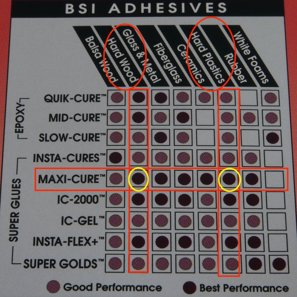
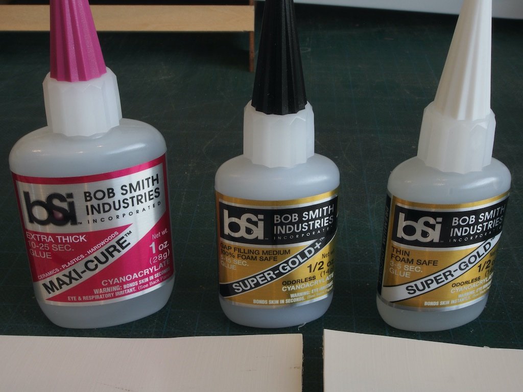
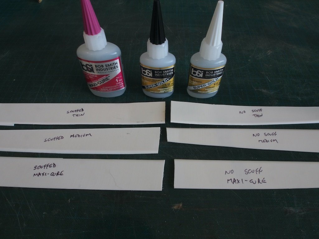
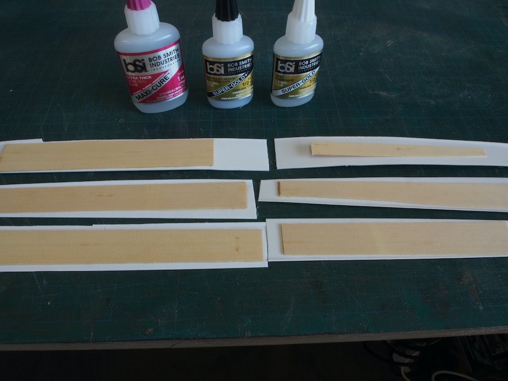
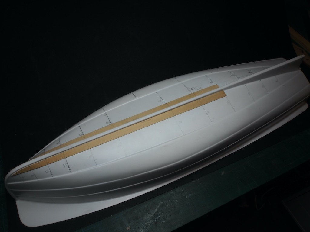
A few distractions have kept me out of the shipyard lately, but progress has been made. Time for a minor update to show "proof of life". I had been pondering the selection of glue for attaching the AYC planks to the ABS hull. In my LHS, I came across this chart from Bob Smith Industries. As can be seen, there is a happy intersection for both Hardwood and Hard Plastics with the Maxi-Cure Superglue, showing up as “Best Performance” in the chart. As I needed to replenish some other glues as well, I decided to do a comparative test with both a Thin and a Medium Odorless “Super-Gold” (both listed as “Good Performance” in the chart). My test comprised using some scraps of the ABS (from cutting the vertical waste section away from the hull) and some scraps of AYC. The guy in the LHS suggested scuffing the ABS with some coarse sandpaper first, so I incorporated both scuffed and un-scuffed into the trial. The glue was applied, and the pieces were left lightly clamped overnight. The results were quite impressive. The only real failure was the “Thin” Super-Gold. All other glues held and there was no discernible difference between scuffing the ABS and not scuffing it. On the strength of that test, I was happy to proceed using the Maxi-Cure without scuffing. Contrary to my previous post, I decided that prior to installing the internal supports, it would be useful to attach the Sheer plank while the excess horizontal ABS was still in place so that it could be used as a reference. The excess could then be trimmed off, which would make clamping the internal supports easier. I also decided that it would be easier to attach the Garboard and at least the first (lower) band of hull planks before attaching the Sheer. The ABS formed hull has moulding lines that I will use as de facto “bands” for planking. The maximum width of most of these is about 42mm, so I have ripped my AYC boards into 14mm widths, meaning that there will be three planks in all of the “bands” bar one, which will receive four planks. I was then able to do a form of lining off by marking on the ABS hull where each band narrowed to a convenient measurement - ie a multiple of three (or four) as appropriate. These marks can now be transferred to the planks to assist with tapering. I’m using a small block plane to taper the planks, and this is proving to be both easy and quick. In the picture below, the forward end of the Garboard plank has been tapered and shaped. A small travel iron was used to create some preliminary bend, and then the Maxi-cure glue applied to the plank. It was only necessary to apply finger pressure for a few seconds while the glue grabbed. Given that I’m making it up as I go along, I’m happy with how that one went, so will continue with this method.
- 57 replies
-
- 11
-
-
- live steam
- radio
- (and 2 more)
-
Great work on the Corvus Glen. Enjoy the vacation - we’ll leave a light on for you.
- 290 replies
-
- 4
-
-

-
- Quinquereme
- Finished
- (and 1 more)
-
Alfa Romeo Spider Touring Gran Sport by CDW - Pocher - 1:8 Scale
gjdale replied to CDW's topic in Non-ship/categorised builds
There is definitely some logic to it. Without going back and poring over it again, I’m pretty sure that Paul Koo covers this in his written instructions. If I recall correctly (and that’s no guarantee!!!), he talks about it in the introductory part. However, as my wife will tell you, these days I am far more often certain than I am right! -
It's the stuff that model aircraft guys use to cover their wings. You should be able to pick it up any LHS, or online. Here's an example from a quick search on the Australian e-bay site: Deluxe BD73 Eze Tissue Paper 12.5 gsm Natural 5 x Sheets 500mm x 750mm
- 290 replies
-
- 5
-
-
-
- Quinquereme
- Finished
- (and 1 more)
-
Yeah, right! 🤣
-
Would that perhaps be an opportunity for you to experiment with using Silkspan for the sails Glen? Would be easy to paint on the eagle, which at that size needn’t be much more than a blob.
- 290 replies
-
- 5
-
-
- Quinquereme
- Finished
- (and 1 more)
-
Great to hear Bob. I’m still in love with my Trek Domane+ too. 🙂 Now, back to regular programming….
- 57 replies
-
- 6
-
-
- live steam
- radio
- (and 2 more)
-
Thanks Bob, Always nice to have you along for the ride. 🙂 Speaking of rides, have you been on your bicycle lately? I find myself riding more and more often nowadays - sometimes 5 or 6 days per week.
- 57 replies
-
- 8
-
-
- live steam
- radio
- (and 2 more)
-
Good to see you back at this interesting project Alan.
-
Thank you very much one and all for the very kind comments. 🙂
-
Thanks Ras, I’ll keep that in mind as a “fix” if needed. Hopefully the steam plant I have will do the trick.
- 57 replies
-
- 7
-
-
- live steam
- radio
- (and 2 more)
-
Welcome aboard Richard - happy to have some more company on this one.
- 57 replies
-
- 6
-
-
- live steam
- radio
- (and 2 more)
-
Thanks Mark, Yes, found that one. Not much help I'm afraid though.
- 57 replies
-
- 4
-
-

-
- live steam
- radio
- (and 2 more)
-
Thanks Ken, Yes, that is the plan, and if I can pull it off, the figures will contain concealed servos….. (an idea I picked up from someone else). That said, this will be an evolving build and some of my current plans may change as we go, either by necessity or to be replaced by another TGI (Thundering Good Idea)!
- 57 replies
-
- 8
-
-
- live steam
- radio
- (and 2 more)
-
Thanks Steven, That is of course the first thing I did - search the forums, but the search turns up no actual build logs - only a completed model in the gallery and some discussion about plans and figures. I’ve also tried other forums, but to no avail. If anyone can point me to an actual build log, that would be very much appreciated.
- 57 replies
-
- 4
-
-
- live steam
- radio
- (and 2 more)
-
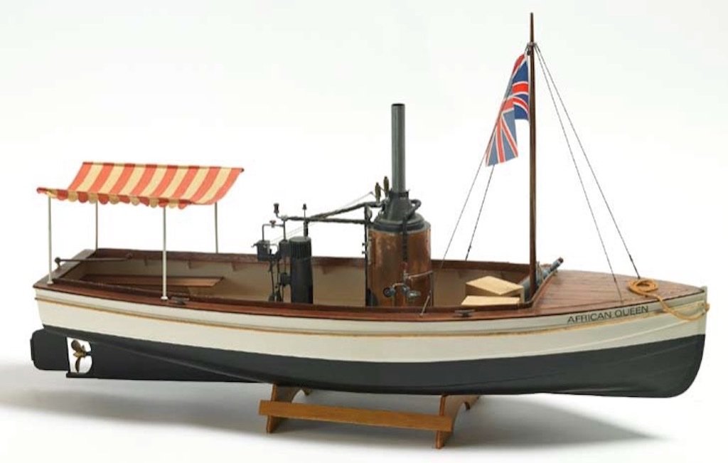
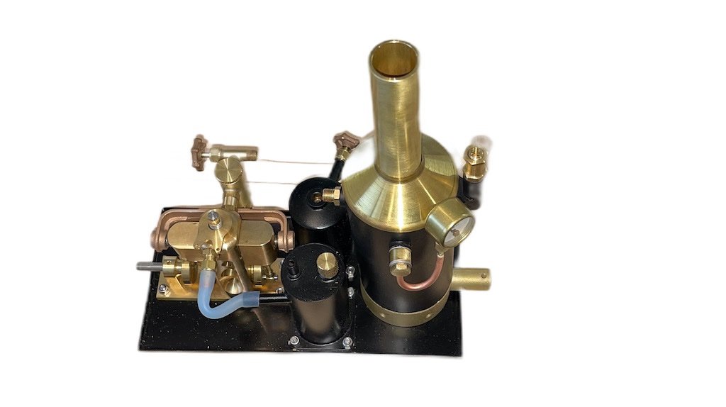
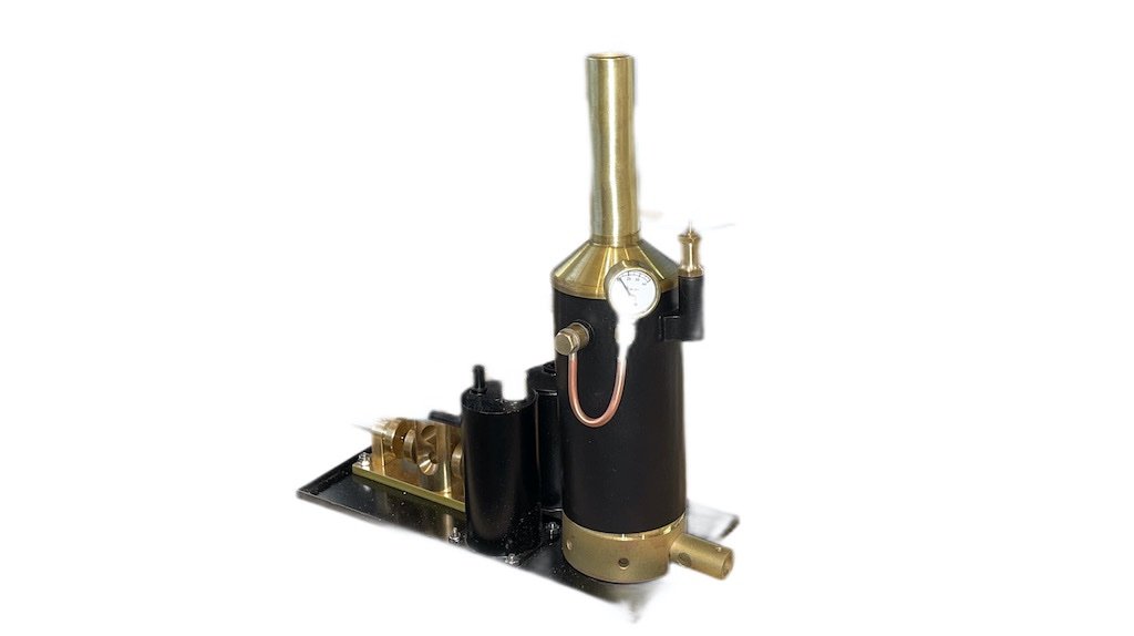
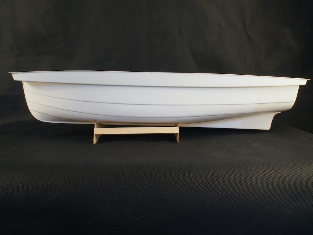
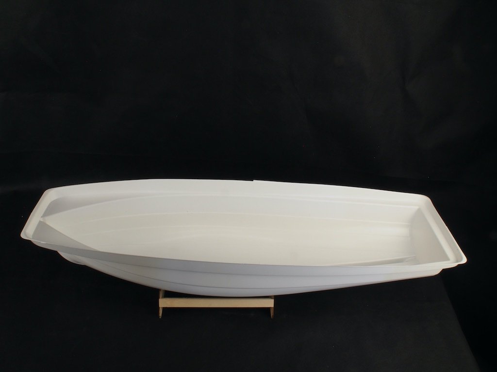
Introduction I have long had a hankering to build a small launch with live steam propulsion. The African Queen seemed to be an ideal choice of subject, however finding a kit to modify proved somewhat elusive. In the end, I settled on the Billings offering in 1:12 scale as it claims to be suitable for Radio Control (albeit using an electric motor). Here is a picture of the box art. The next challenge was finding a steam plant suitable for inclusion in the model. After an exhaustive search, I settled on a complete steam plant from Miniature Steam Models (MSM) in Melbourne, Australia. It is a 2” boiler with the “Avon” twin cylinder double acting oscillating steam engine. The steam plant comes complete with a boiler certificate and the engine is matched to the size of the boiler. For the tech heads, it has an 8mm bore and an 11mm stroke (and it is reversing). Overall, it is very similar in size to the “fake” boiler/engine plant provided in the Billings kit. Here are a couple of pictures of the steam plant as provided from MSM. What’s in the box? The Billings kit is fairly typical of the Billings offerings. The hull is provided as a single-piece vacuum formed ABS mould. The rest of the kit includes a variety of laser cut plywood parts, some strip wood (not particularly high quality), some brass components and some plastic components. As I will not be using the provided boiler/engine parts, a lot of these will be redundant. I was concerned by the apparent flimsiness of the hull, and my plan is to sheath the hull in timber, and then fibreglass over the top of that. To this end, I have obtained some 1mm thick Alaskan Yellow Cedar from Hobby Mill EU to be cut into planks as appropriate. I will also be adding some aftermarket timber for the deck planking, as the kit would have you simple draw planking lines onto the provided plywood. I’m currently in the process of placing an order for this with Hobby Mill EU. Instructions are, I believe, typical of Billings – which is to say, next to useless. This is not a kit for a beginner, although it is marketed as “Advanced Beginner”. We shall have to see whether I have sufficient skills to pull this off – otherwise, there is considerable investment “down the tube”. The Hull Here are a couple of pictures of the ABS hull. As can be seen in the pictures, there is a considerable excess lip around the upper edge. I will need to remove the vertical component of this before I can do anything else. My current plan is to do that, and then fit the internal frames to provide some stiffening before attempting the outer planking. Welcome aboard for what might prove to be an "interesting" journey!
- 57 replies
-
- 19
-
-
- live steam
- radio
- (and 2 more)
-
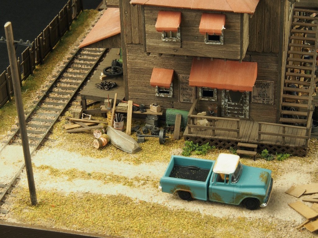
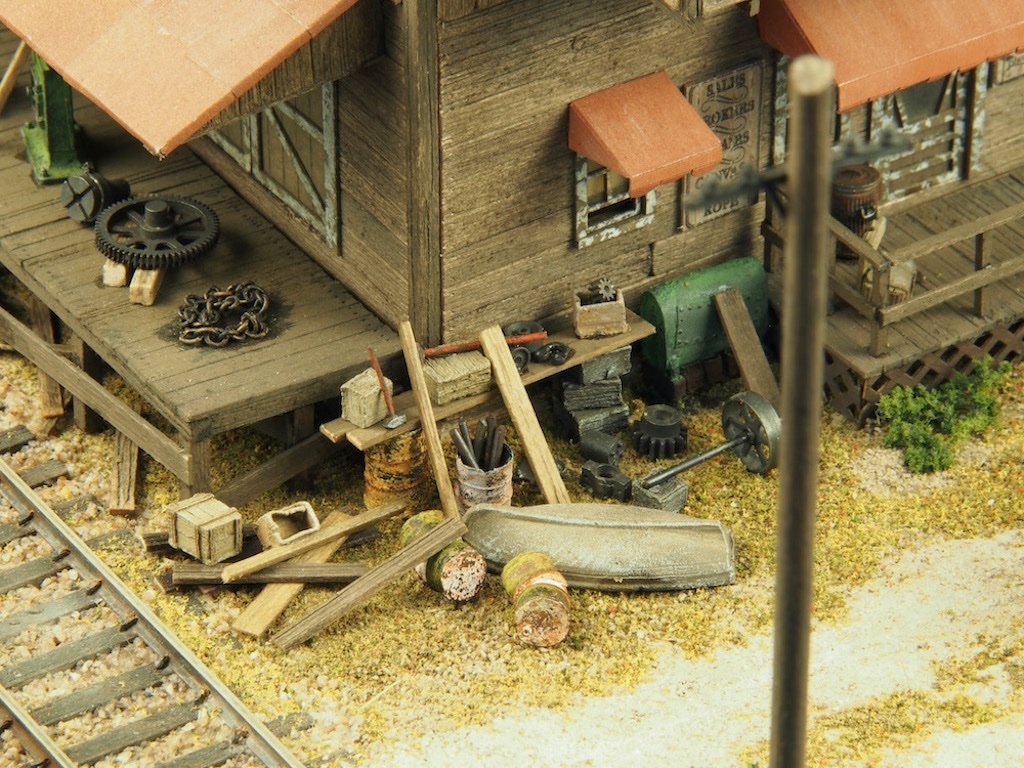
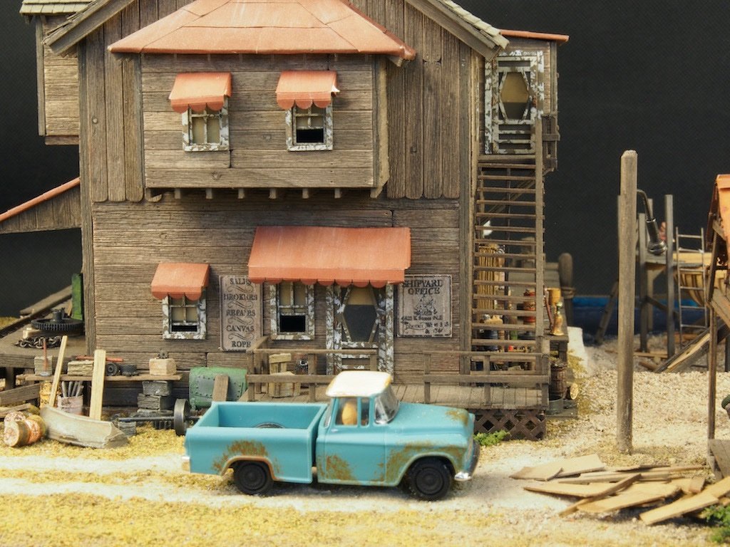
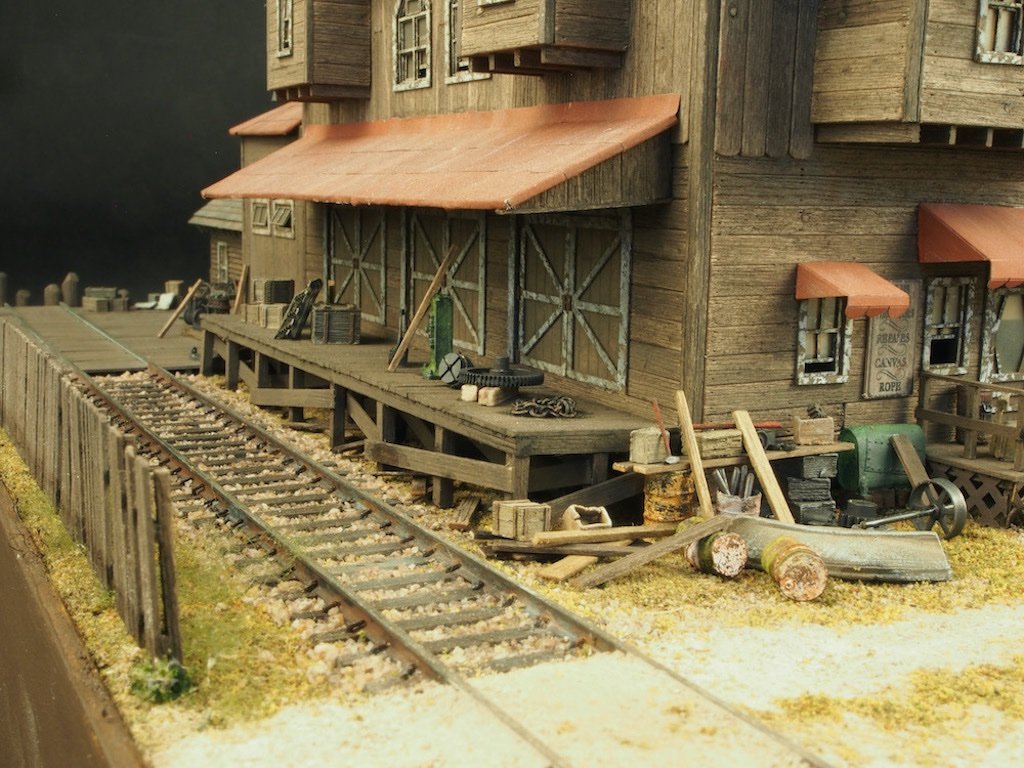
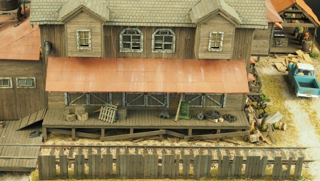
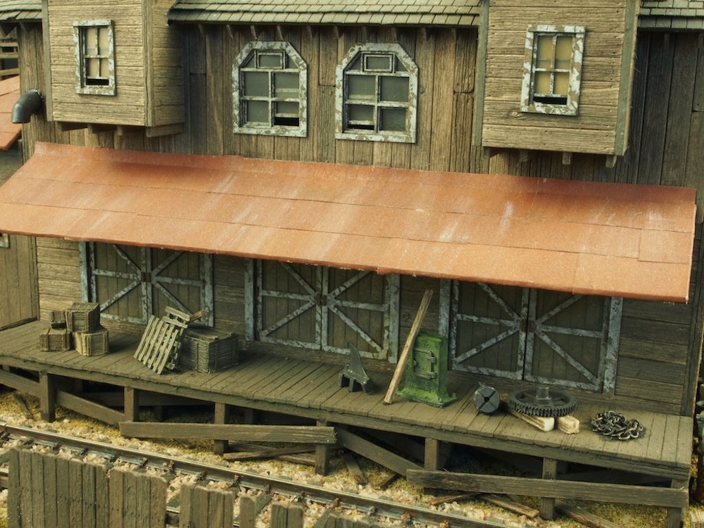
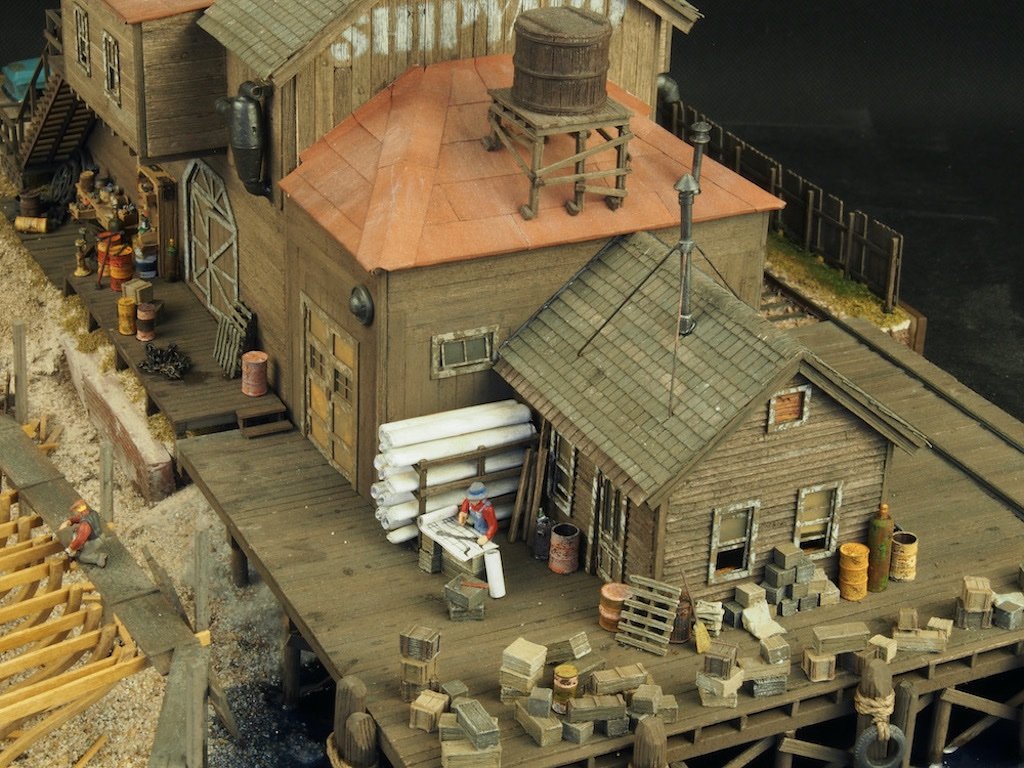
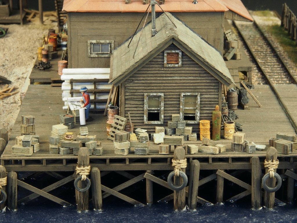
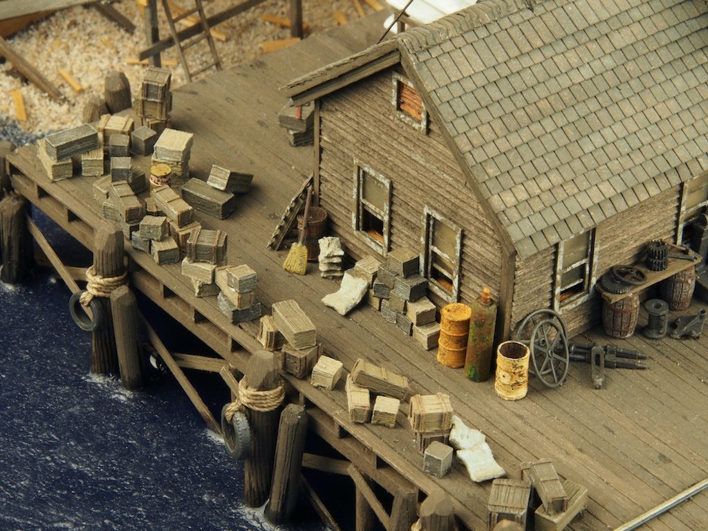
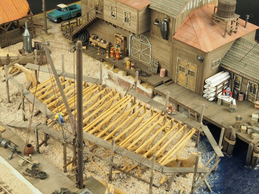
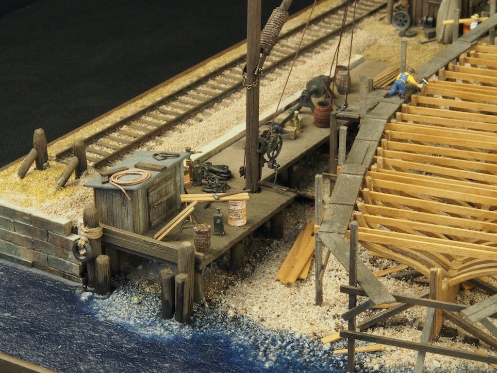
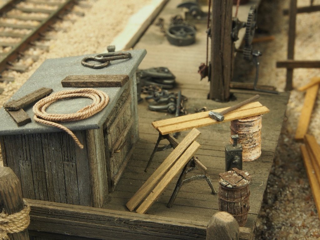
Continued from previous post... The Loading Dock The Main Dock That completes the series of "glam" shots and brings this project to a close. I'd like to thank all of you who have followed along and offered support, encouragement and advice along the way. This has been a most enjoyable diversion into this style of modelling and I've learned a lot along the way. i do have another of these kits in my stash (Foss's Landing), but I've got a ship or two to build first. Stay tuned for the next exciting adventure!
- 333 replies
-
- 31
-
-

-
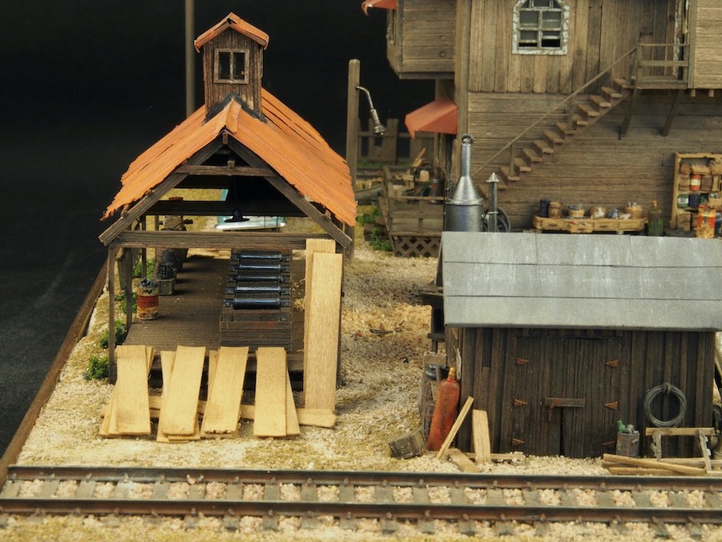
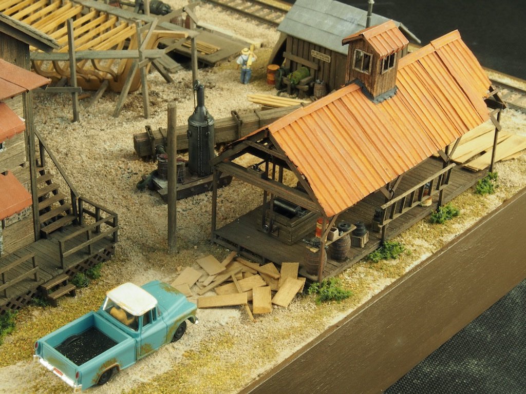
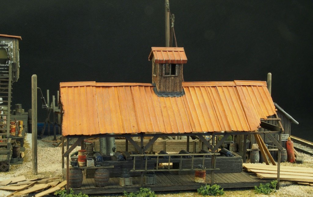
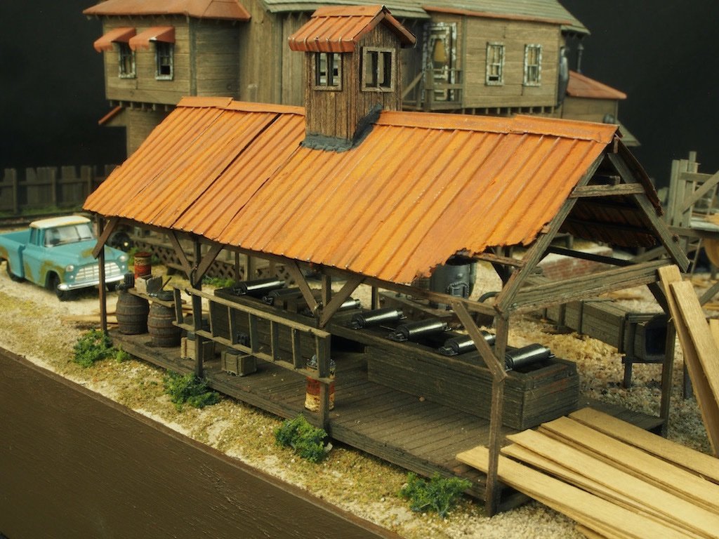
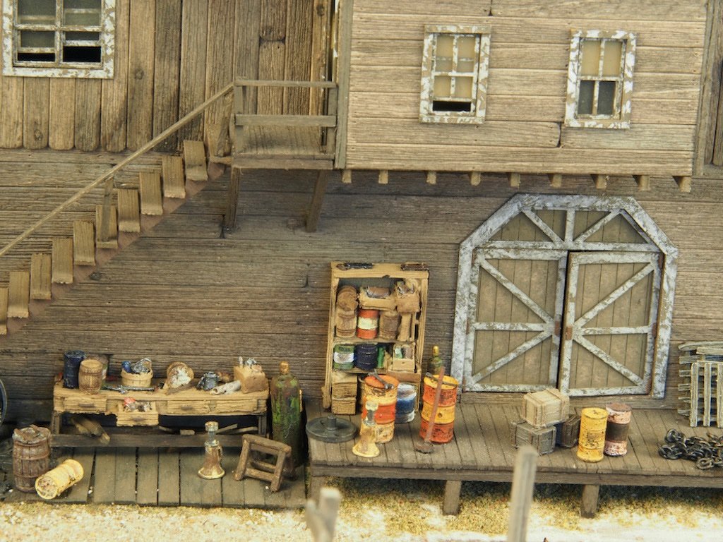
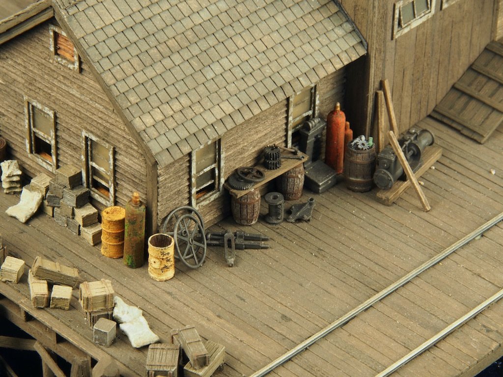
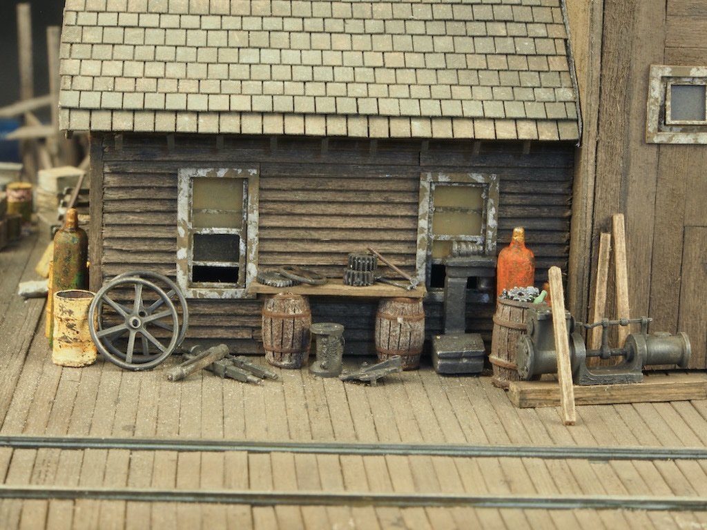
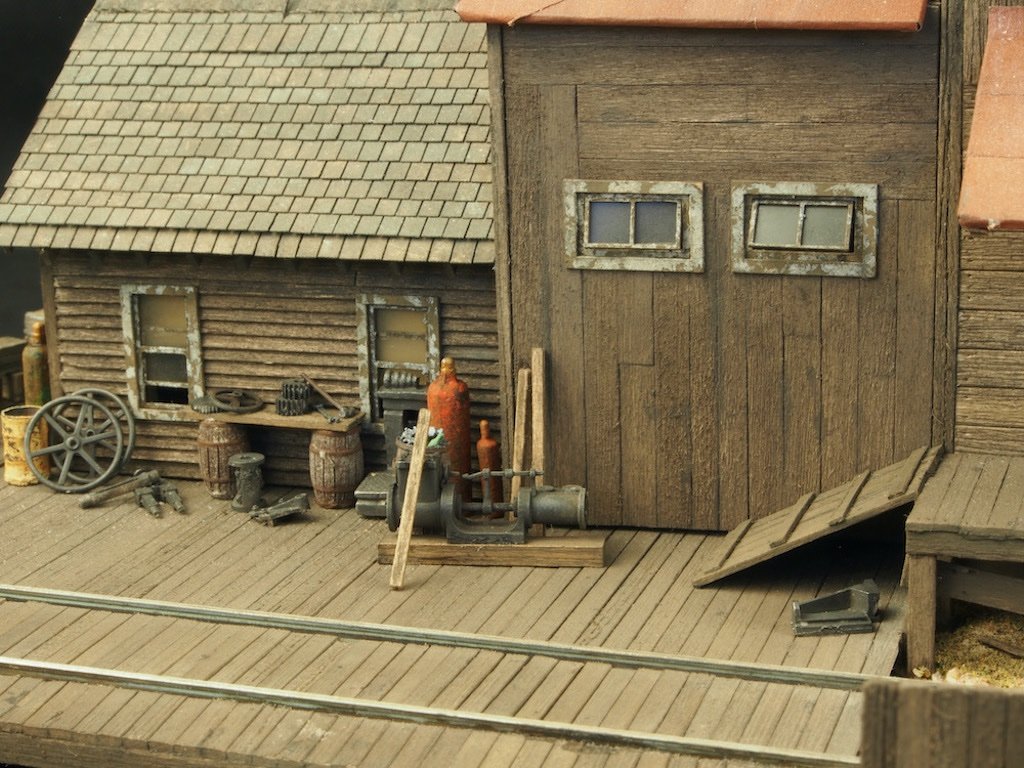
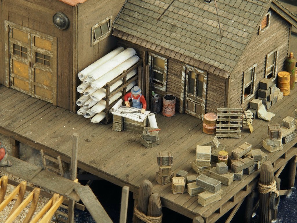
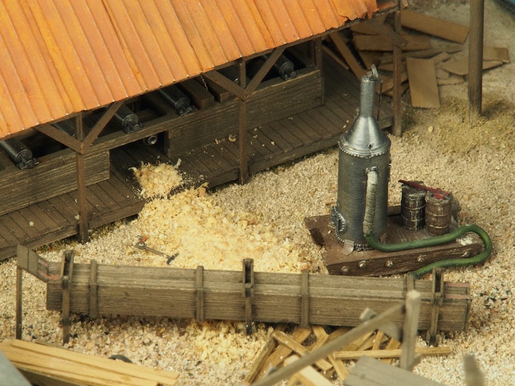
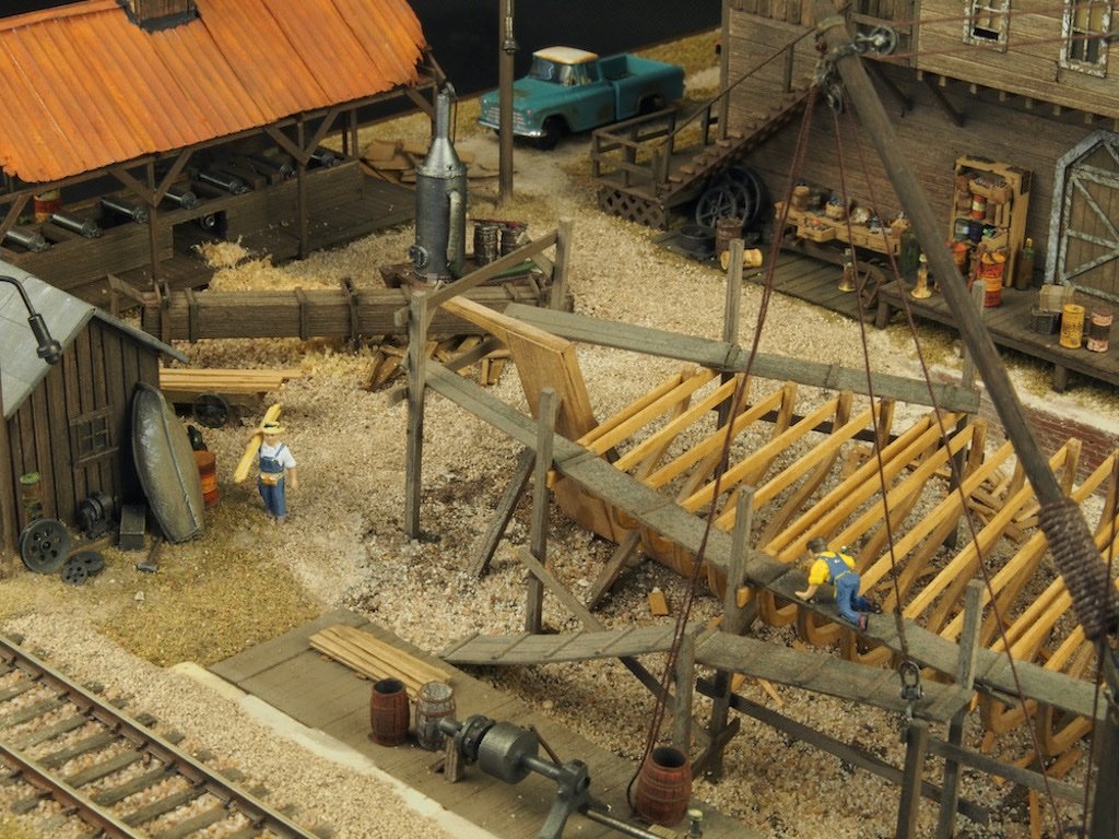
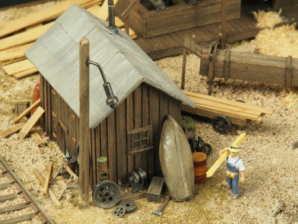
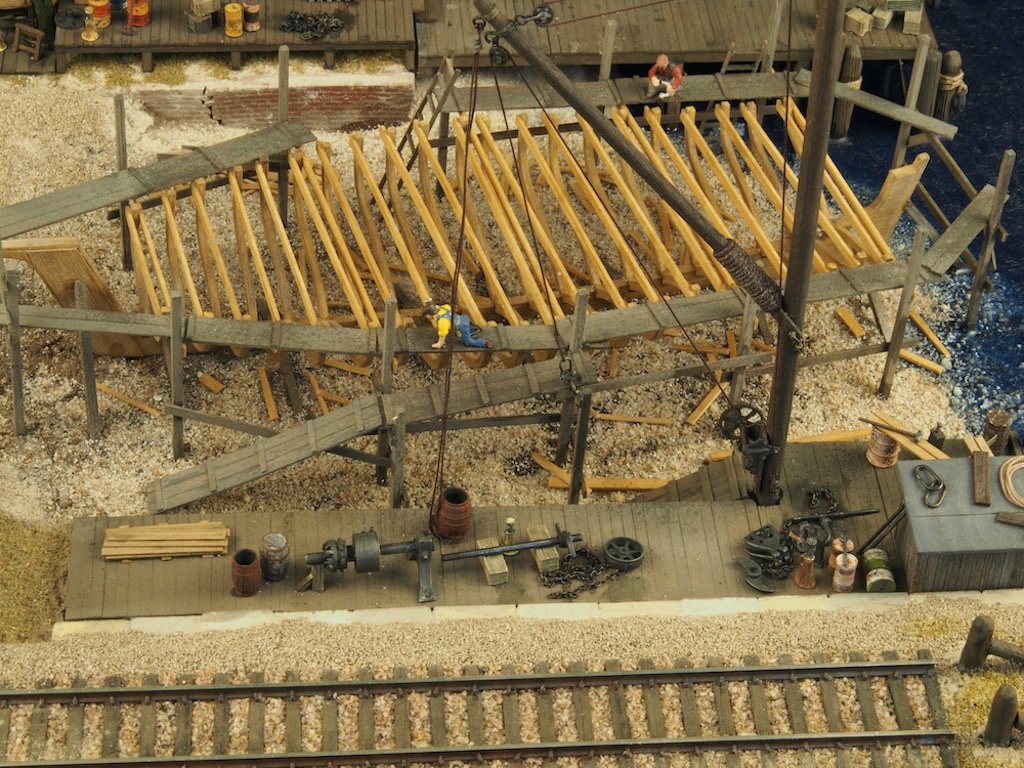
Continued from previous post... Some of the individual "scenes". The Ship Under Construction The Yard Master (studying the plans) The Steam Box The Upper Yard Shed The Derrick Dock Continued next post...
- 333 replies
-
- 18
-
-