


gjdale
-
Posts
4,894 -
Joined
-
Last visited
Content Type
Profiles
Forums
Gallery
Events
Everything posted by gjdale
-
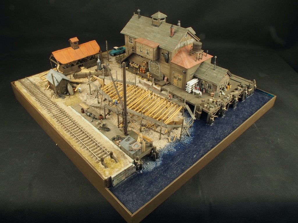
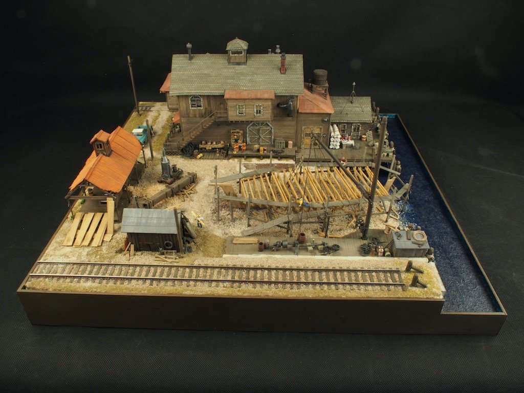
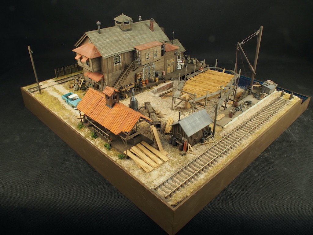
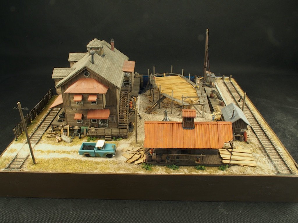
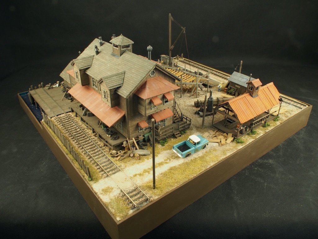
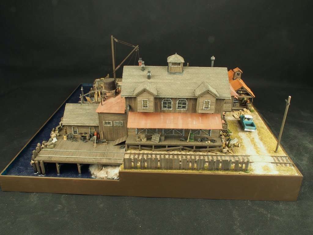
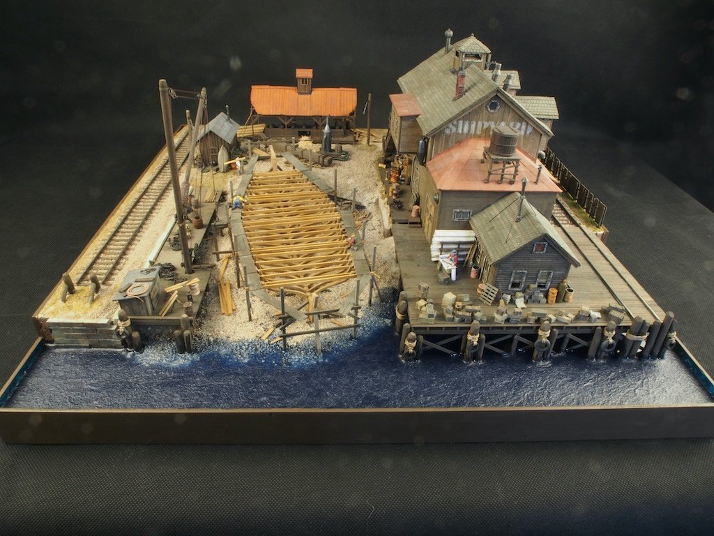
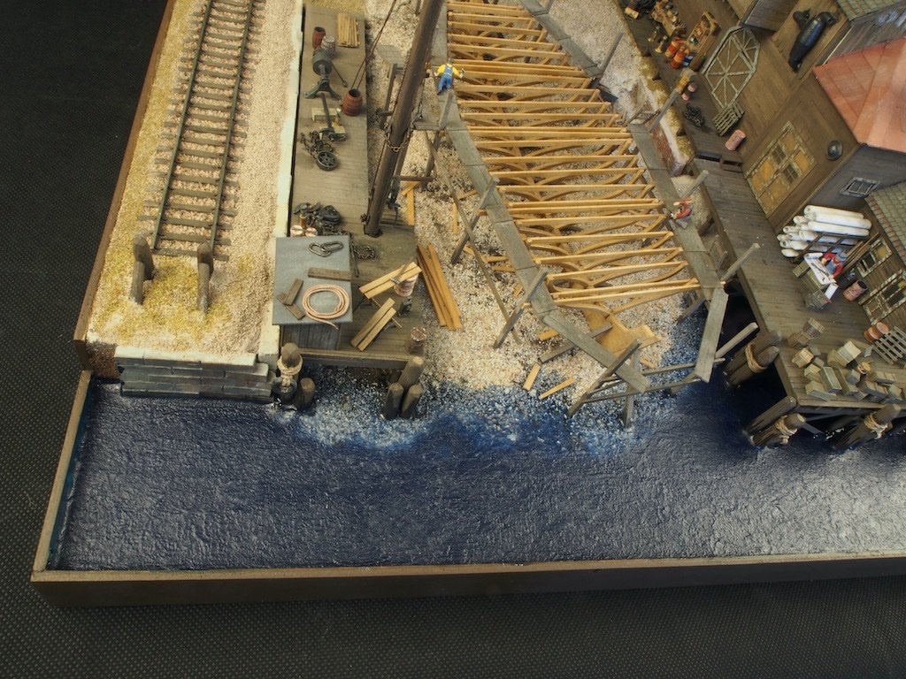
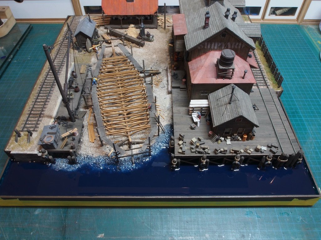
 Thanks very much Keith, Glen, OC, Jack, Yves, Mark and Ken, and also to all of the 'likes'. I didn't quite get around to posting the final "glam" shots yesterday, so here they are. There are quite a few, so I'll split across several posts, starting with the overall "spin" shots. Continued next post...
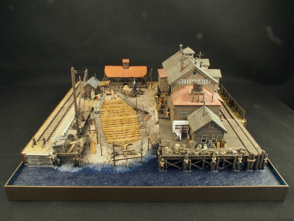
- 333 replies
-
- 23
-

-

-
Very nice work on the bow and stern carvings Glen. And good thinking re the oars too! This is really starting to take shape now.
- 290 replies
-
- 6
-
-

-
- Quinquereme
- Finished
- (and 1 more)
-
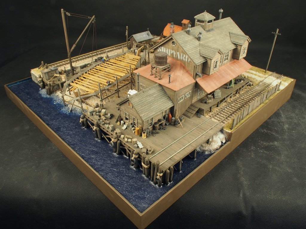
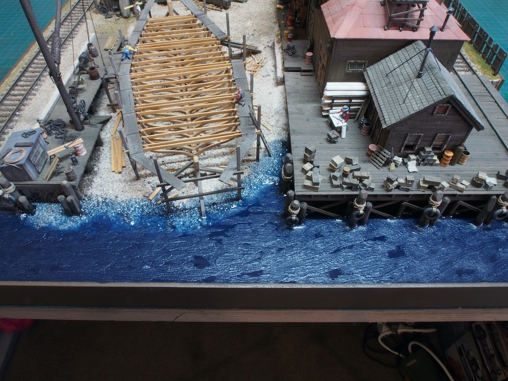
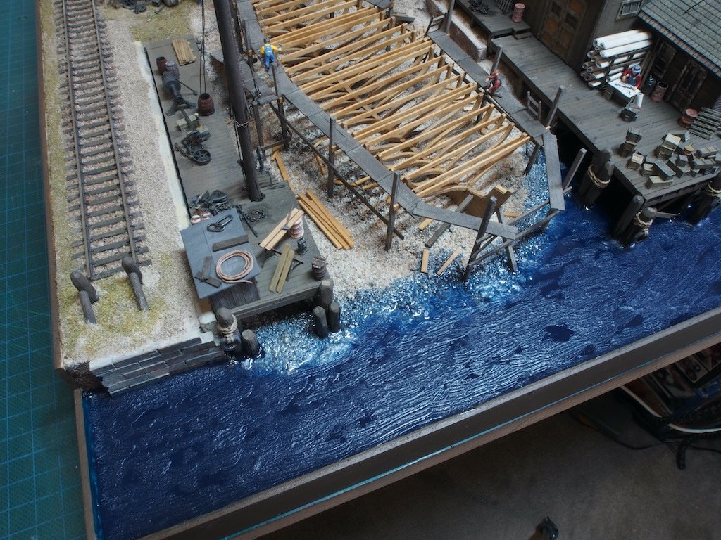
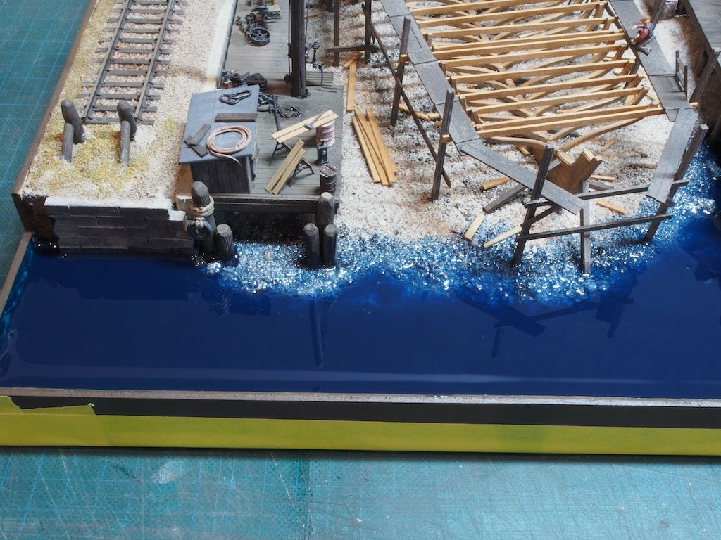
Thanks again for the input guys. I decided to have another crack at the water – I just wasn’t happy with the ripples, nor the smooth patches. So I did two more applications of the Water Gel Effects using a softer stencilling (I think) brush. My aim was to blend in/out the heavy parallel lines that could previously be seen, and also to remove the totally glass smooth areas. I’m happy with the result and am going to call “done” at that. Here’s a few shots of the final version of the water. Final "glam" shots to come later today....
- 333 replies
-
- 19
-
-
-
Thanks for that input Glen. The photo you posted is pretty much exactly the effect I was going for (but still with the odd calm/still patch). I’m going to have another crack at this today - I have a couple of ideas/techniques in mind….
-
Neat solution to a tricksy problem BE. Looking very good.
- 648 replies
-
- 2
-
-
-
- Indefatigable
- Vanguard Models
- (and 1 more)
-
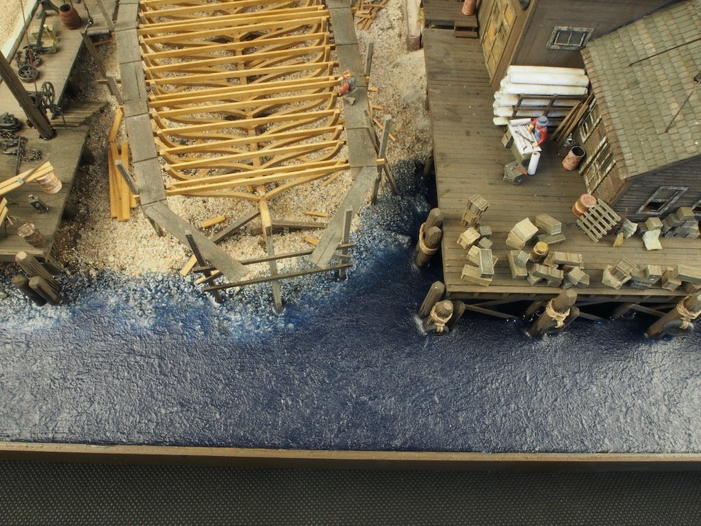
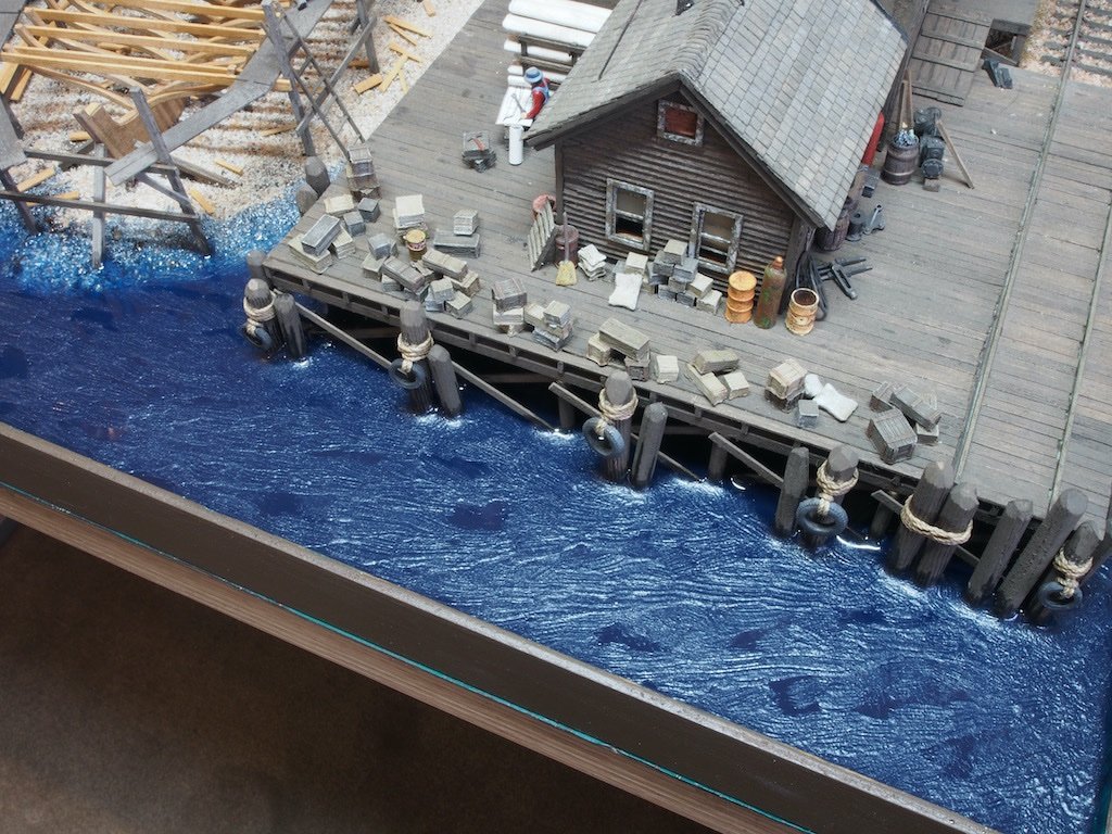
Thanks Wefalck - that kinda aligns with my thinking. The “white foam” around the posts is actually just a trick of the light though.
-
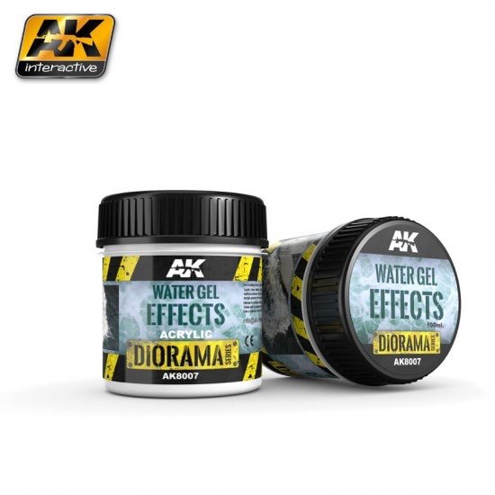
Thanks for all the input guys, and also for all of the 'likes'. Finishing the Diorama – the Water (cont’d) So I acquired some AK Water Gel Effects (AK8007) and applied this with an old fairly stiff brush. The effect I was looking for was that of a gentle breeze across the water surface, with occasional clear patches of no breeze. As this is my first attempt at this process, I would appreciate some further feedback and/or guidance/tips to improve the appearance. Are the "wave lines" too distinct? Would I be better off using a more "stippling" method to remove/reduce the line effect? The good thing about this product is that I can add more to change the effects. Here is the first attempt. Thanks in advance for any and all input/advice.
- 333 replies
-
- 16
-
-
-
Thanks Wefalck and Glen, You’ve convinced me to have a shot at adding some texture to the water surface. I’ve just ordered some of this:
-
Thanks Wefalck, that’s pretty much what I had in mind. 👍 I have no experience with any of the products/brands available though, so was hoping for some recommendations in that regard from those who may have trodden this path before.
-
Thanks very much once again for all the kind comments and the likes. Finishing the Diorama – the Water To complete the diorama, I added an external frame of 3mm plywood, that doubles as a dam for the resin water. Once glued in place, I sealed the inside joins with silicone and then used automotive masking tape to reinforce all of the seams before pouring the resin. I used Envirotex Lite resin as recommended in the instruction manual. I did several small test pours with varying combinations of paint to tint the "water", before settling on a mix of Vallejo Dark Prussian Blue and Black in about a 5:1 ratio. With the testing complete, it was time to take the ‘no turning back’ step and actually pour the water. All seems to have gone well. The pictures below were taken about two hours after the pour. All bubbles seem to have sorted themselves out and I have “embraced the creep”. Not sure yet whether I will apply some paint along the shoreline to change the colour there a little. The other thing I’m not yet sure about is whether or not to attempt adding some texture to the water surface using either a Woodland Scenics product or an AK Interactive product. I’m open to thoughts on this. Here are the photos with the resin still curing. Once I’ve made those final decisions, I’ll take off the tape and take some final “glam” shots.
- 333 replies
-
- 17
-
-
-
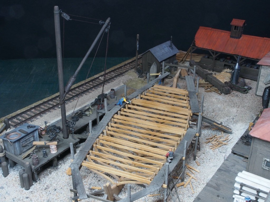
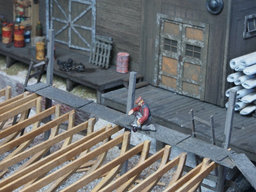
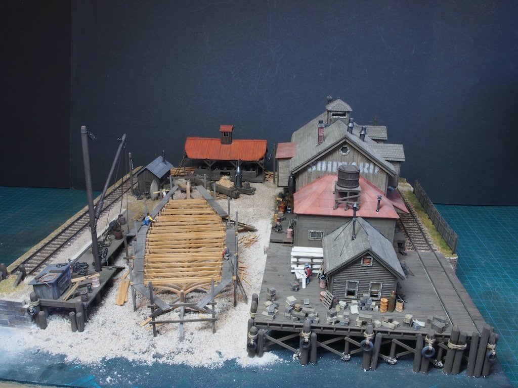
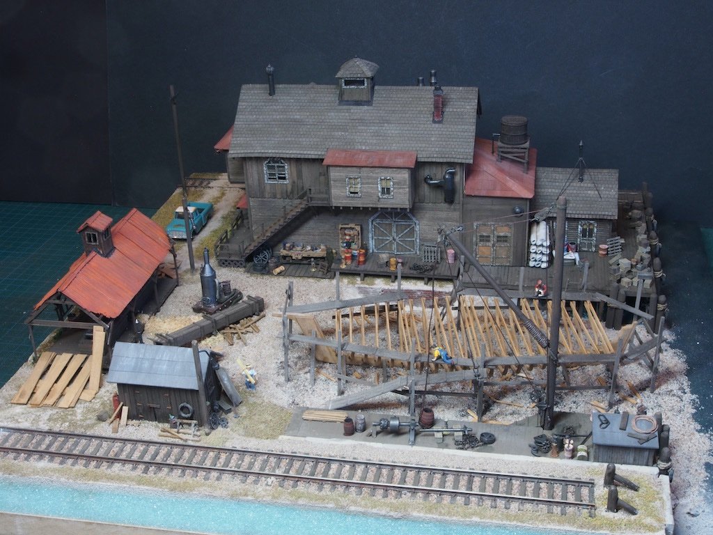
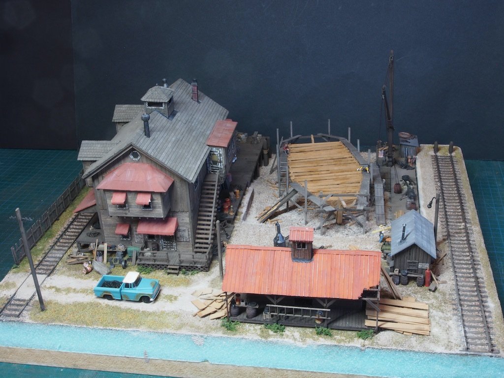
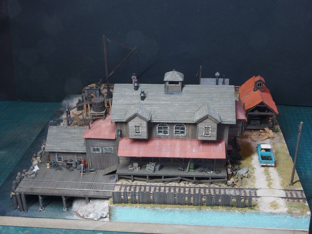
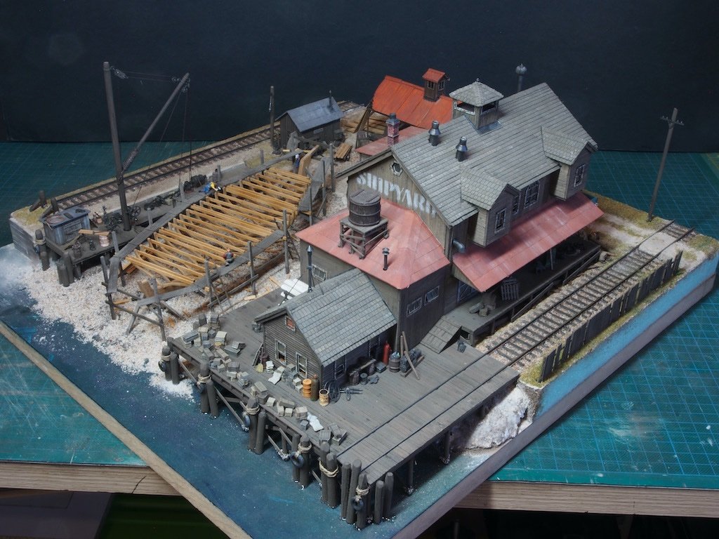
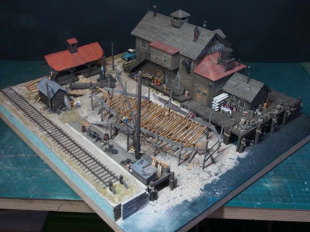
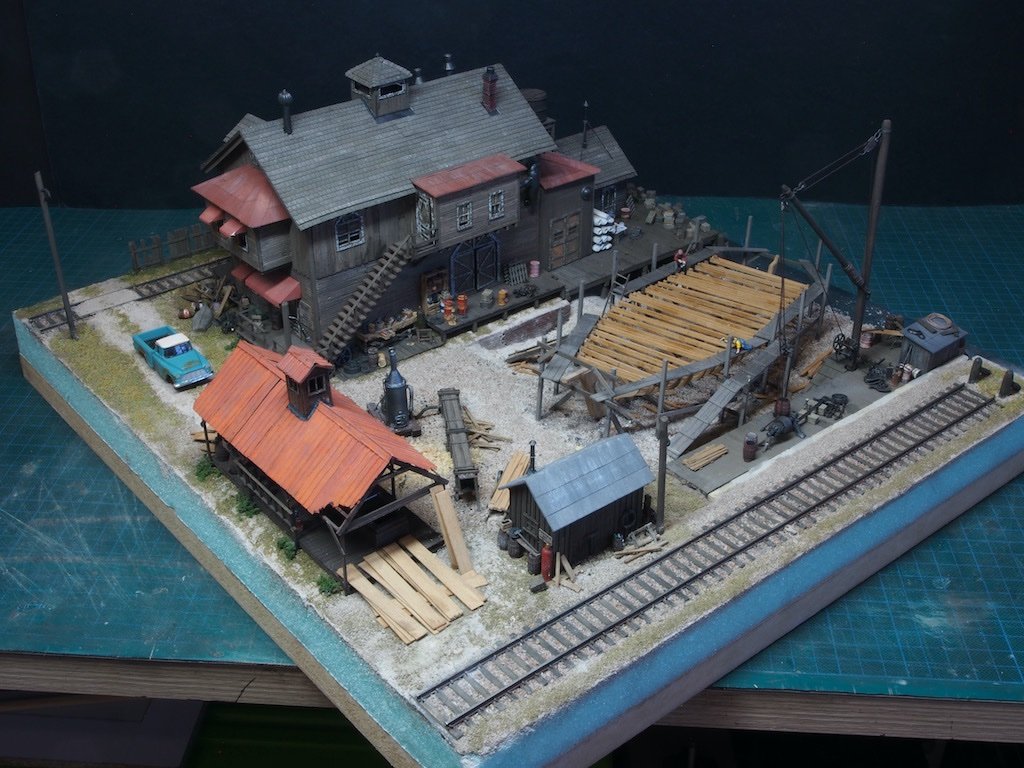
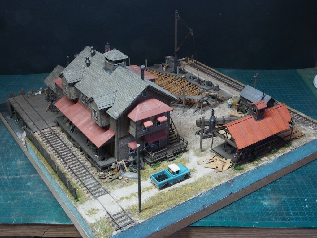
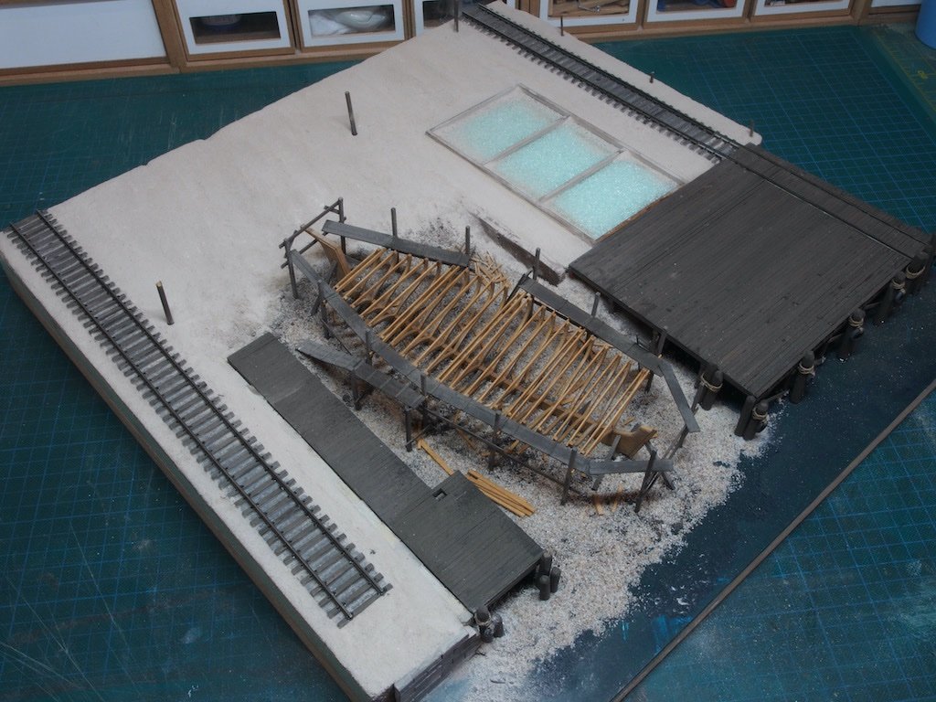
Continued from previous post... A few extra dock yard maties were selected from the Carpenter’s crew and placed in the overall scene. This chap is carrying a load of freshly cut timber over to the ship. Two more are at work on the ship itself. And here’s a close-up of one of these two. Here then are a few “spin” shots showing the overall diorama from all angles. The design of this kit is so clever, that there is no “front” side – take our pick! One thing I didn’t mention earlier, but can be seen in the above photos, is that I wasn’t happy with the light poles or telegraph pole, so I re-made these all from 1/8” dowel (the manual actually specified this for the telegraph pole, so I figured the light poles must be similar). The last task remaining (other than a little touch up here and there) is to pour the “water”. While I’m a little apprehensive about this as there is no going back, the instructions have very little to say about it, other than following the resin manufacturer’s instructions and doing a little test first. I’ve learned along the way that when the instruction manual does not go into great detail, then the process is generally straight forward. (Famous last words).
- 333 replies
-
- 26
-
-
-
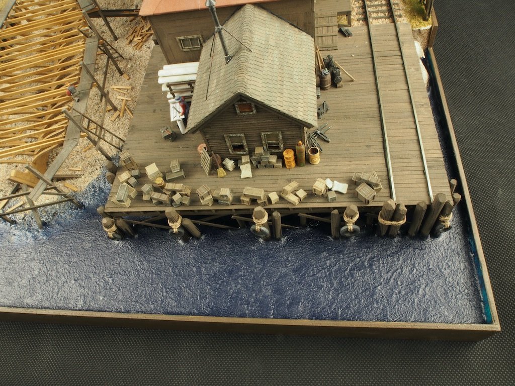
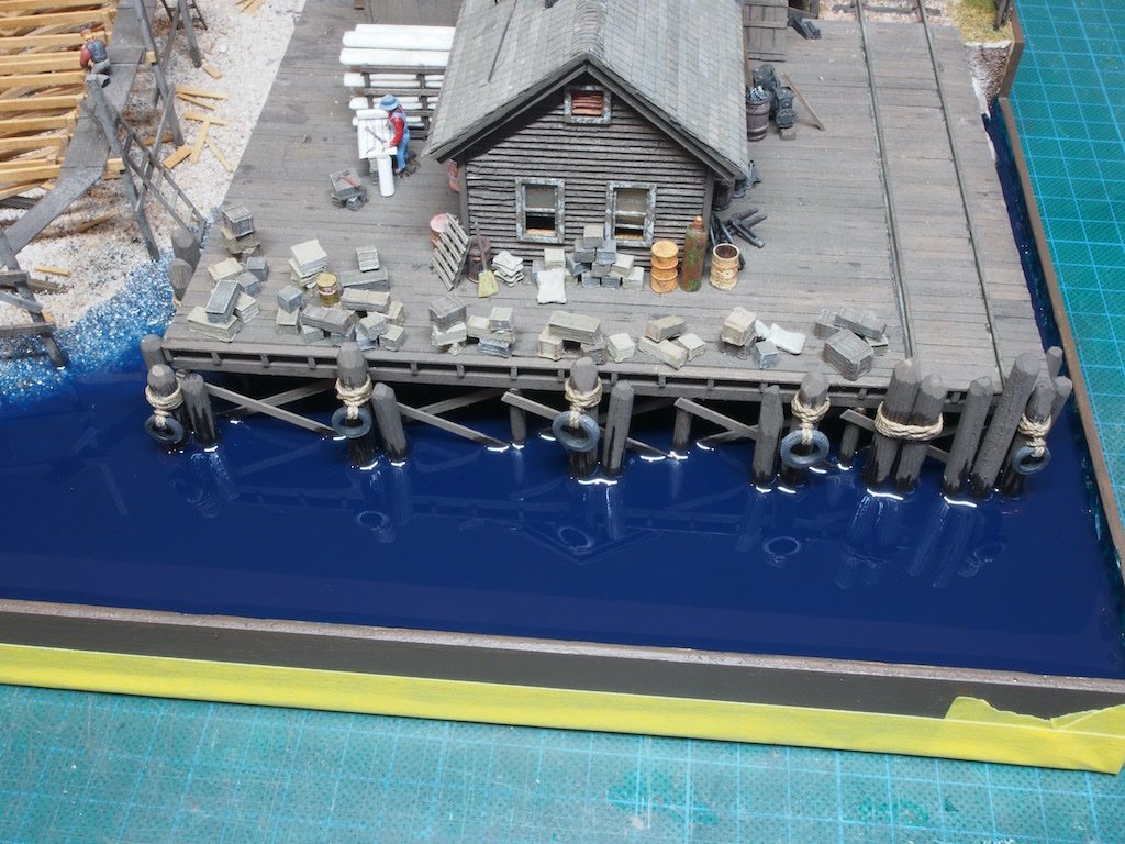
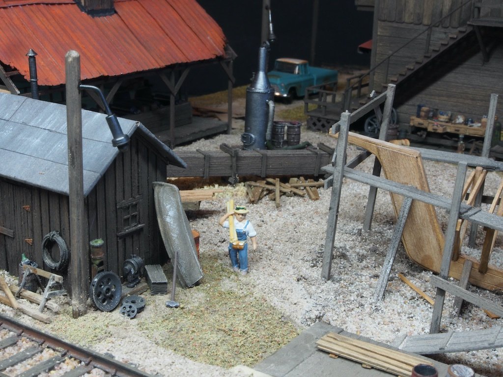
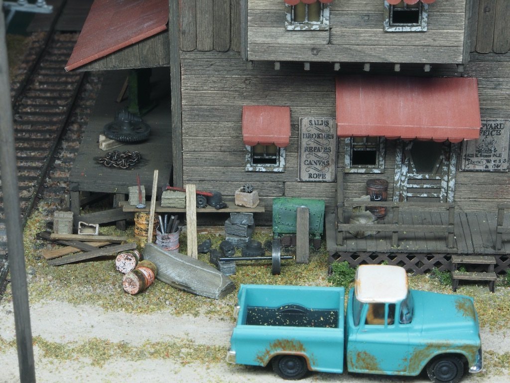
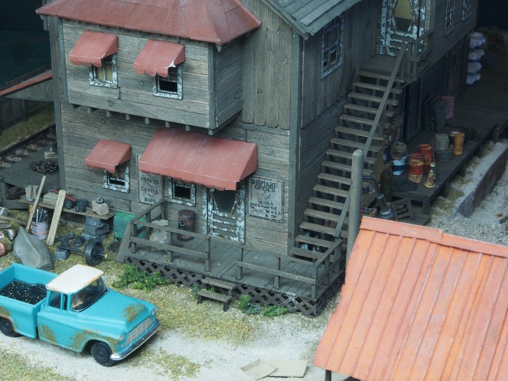
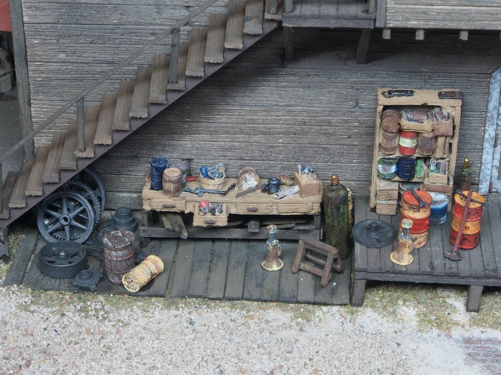
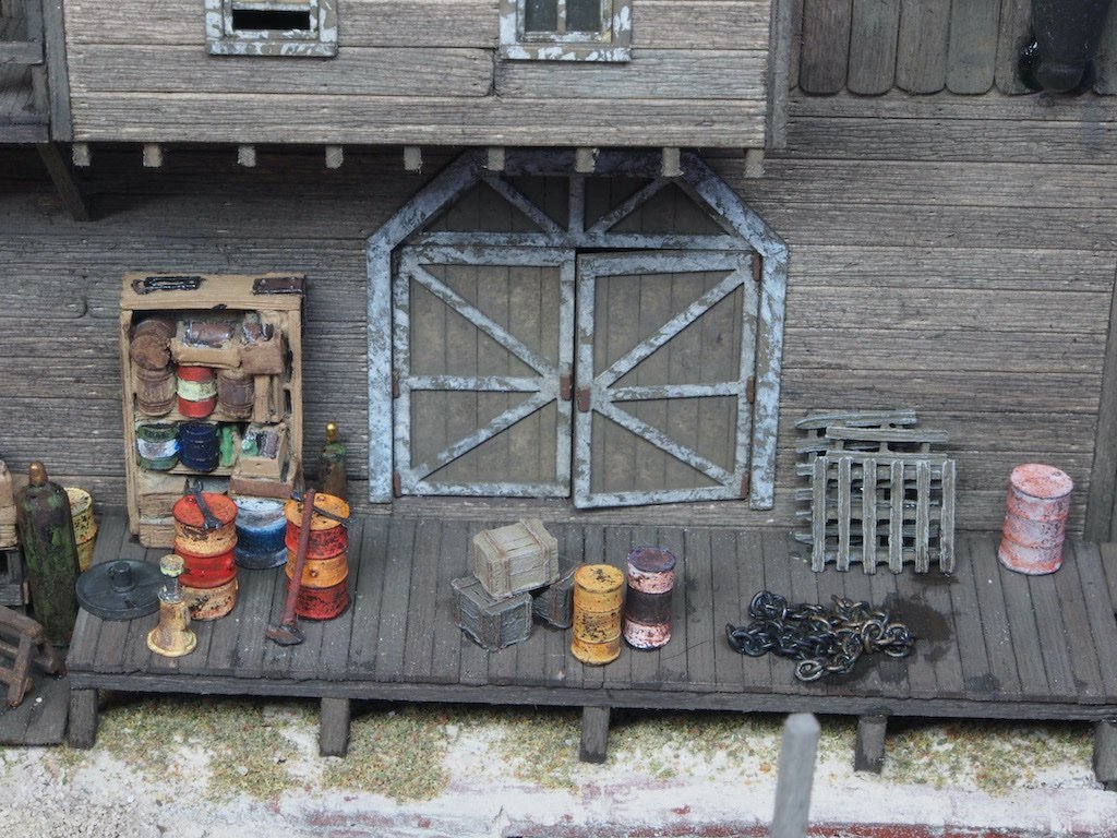
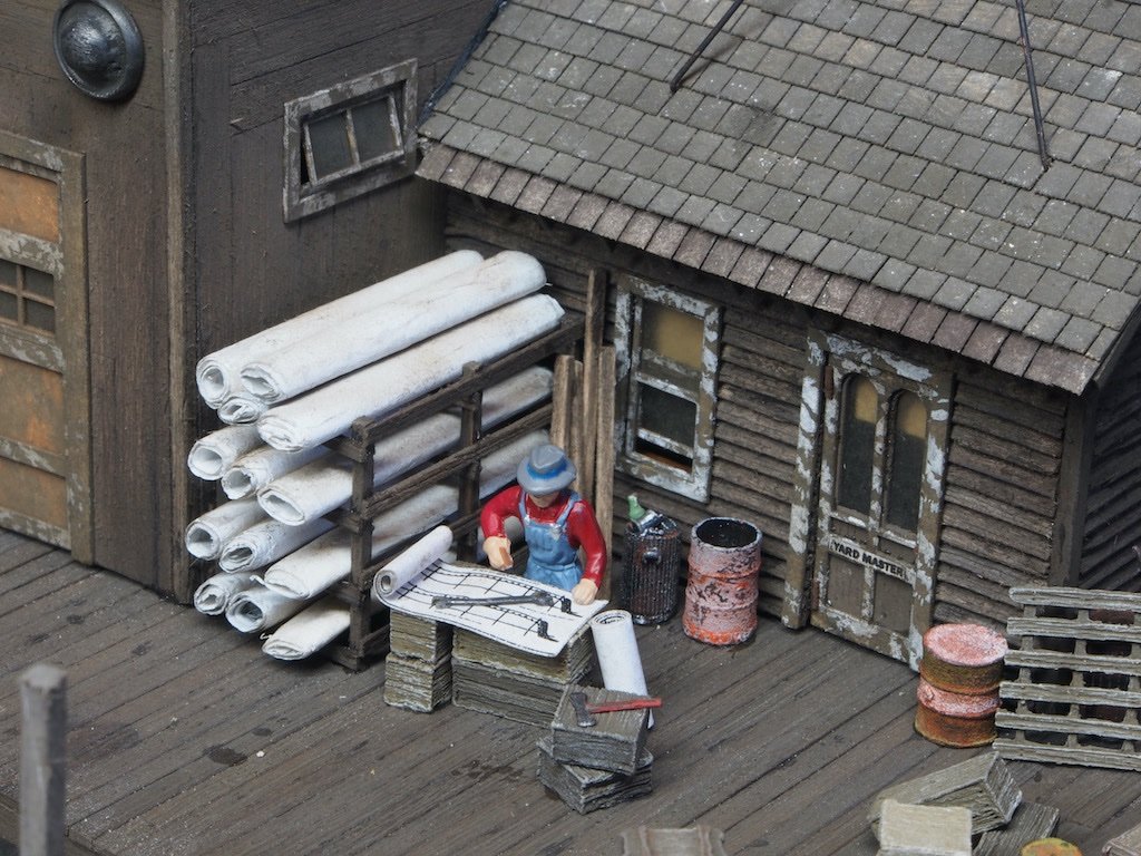
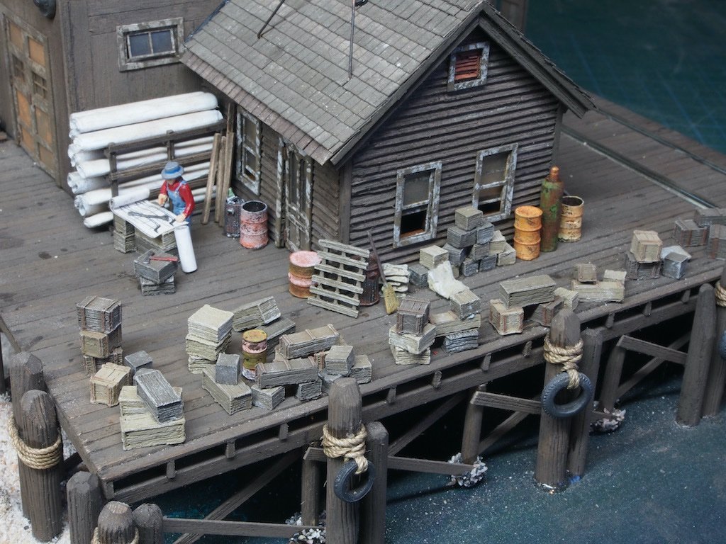
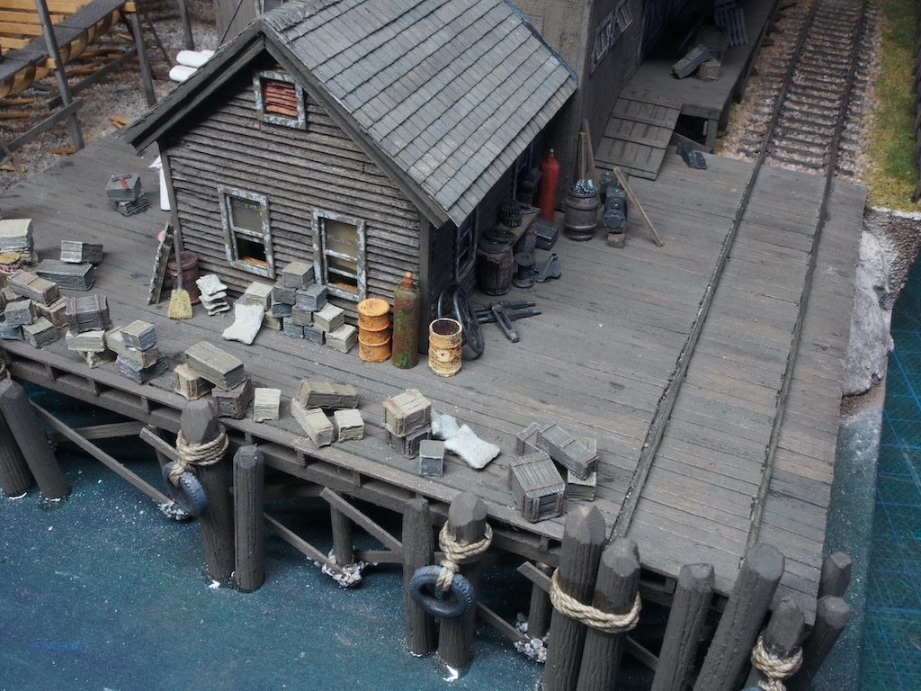
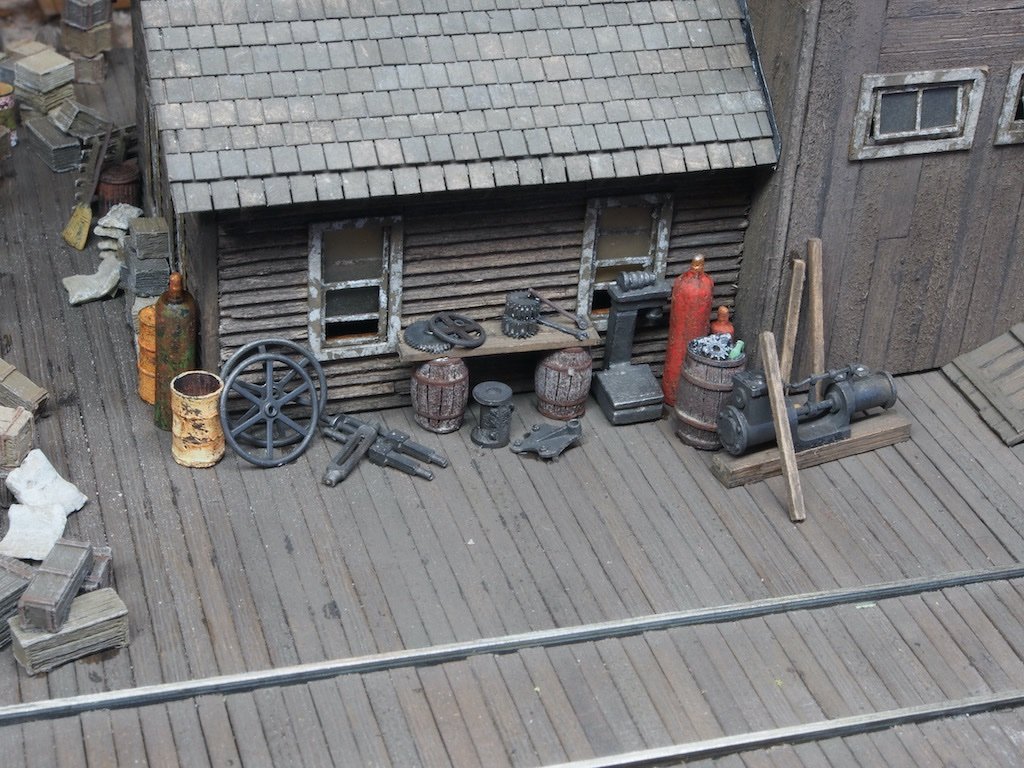
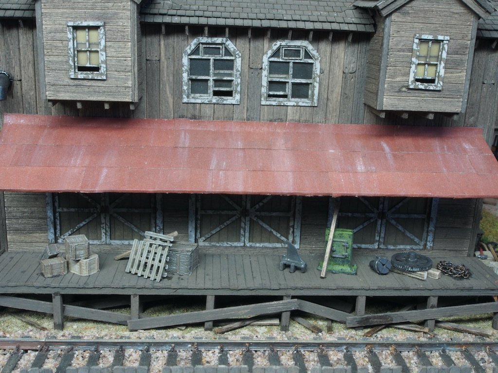
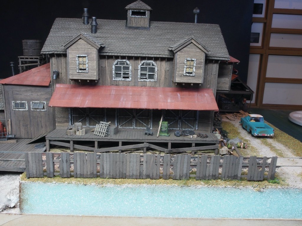
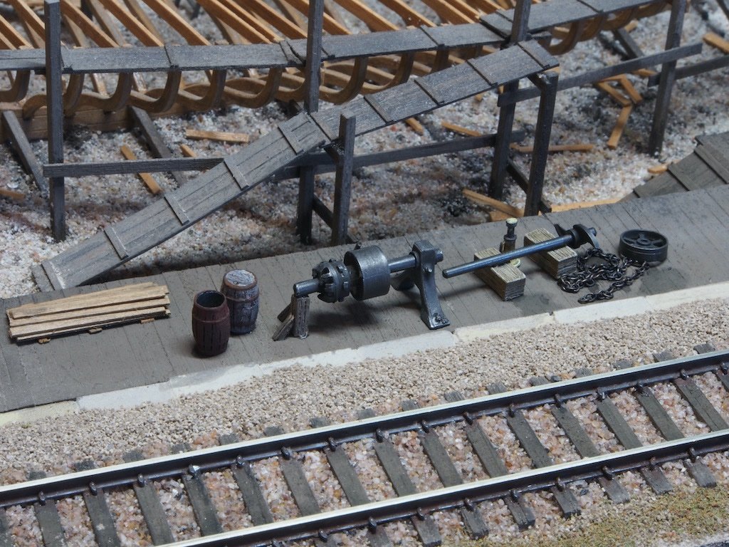
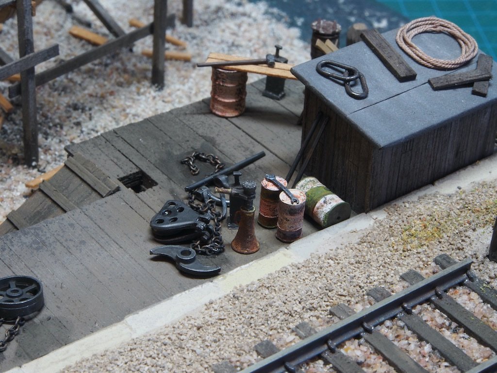
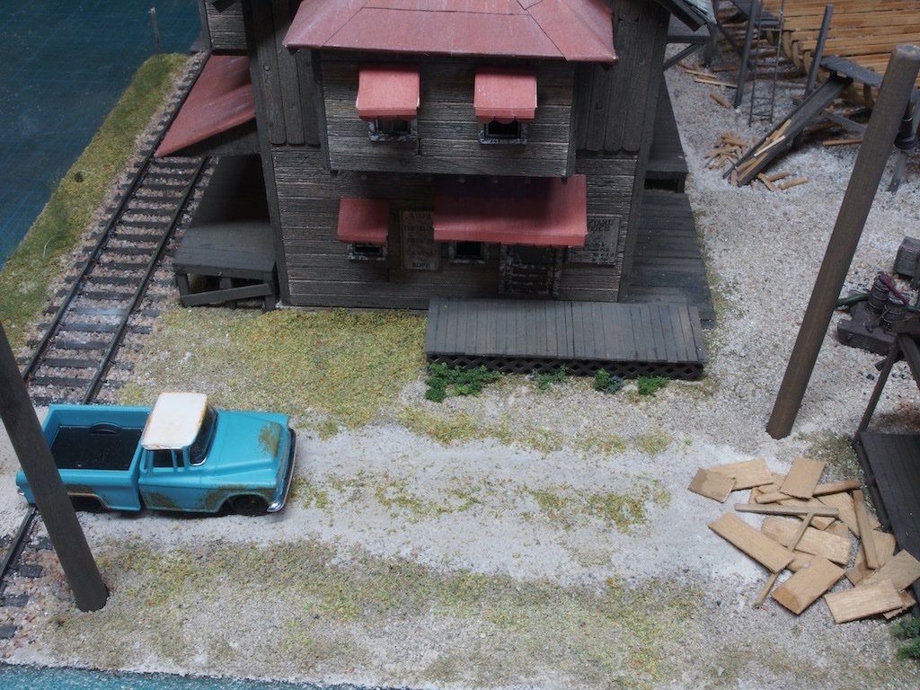
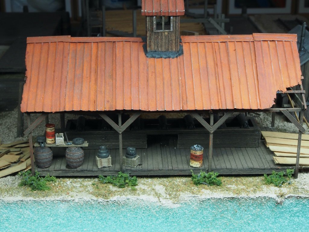
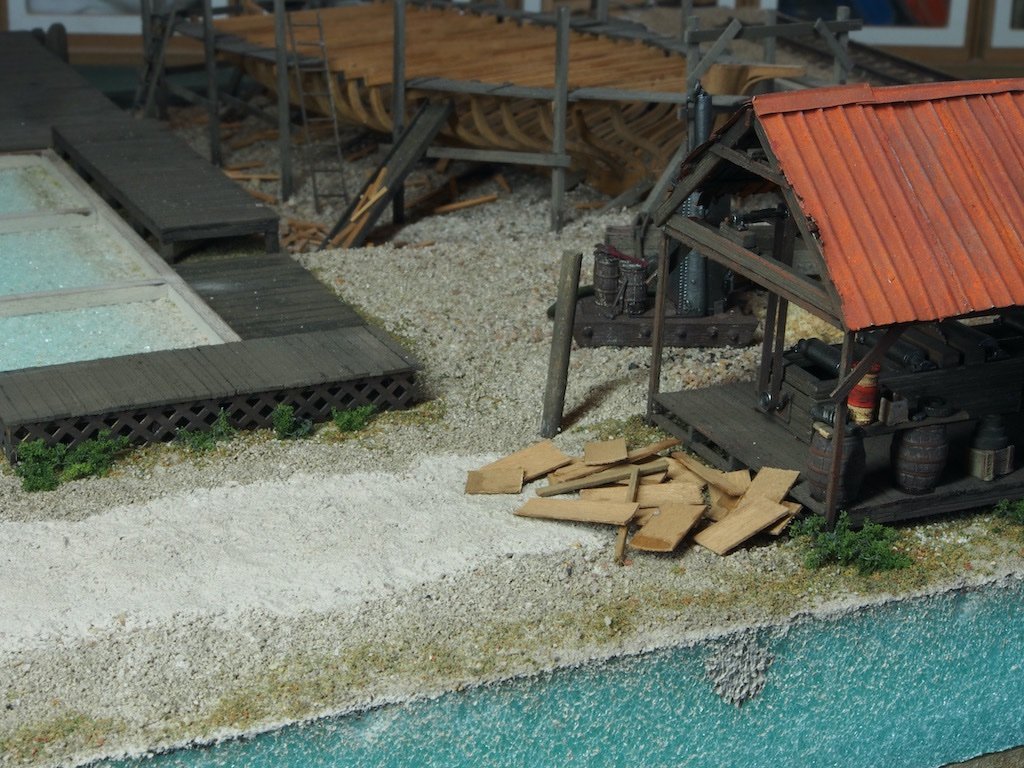
Detailing the Diorama Scenes (continued) A picture heavy update, so I'll spread this across two posts. With the “ground work” complete, it was time to start placing the remainder of the castings around the main building and docks. In doing so, I’ve used the pictures in the instruction manual as a general guide to placement, without copying it exactly. We start with the area outside the Sales Office. Once the castings were in place, the Sales Office Porch was added. This was built in the usual way over a provided template. A two-step set of stairs was also added. In the picture below, I have also added the old truck in its final place. The stairway to the upper storey was then build and added. A set of three laser-cut stringers are provided in the kit, along with a cutting guide for the stair treads. I got so engrossed in what I was doing that I forgot to take any “in-progress” pics of this process but it was a straight forward one. Prior to placing the stairs, the area underneath the stairs was detailed with the workbench and other items various. The workbench was a one-piece casting painted earlier, but legs and bracing were needed prior to final placement. I’ve also added a few scraps of timber under the bench. The left Loading Dock was next. Again, the shelving unit was a one-piece casting painted earlier. All other items are individual castings. Next we move onto the area outside the Yard Master’s Office. I obtained a set of HO Scale figures from Woodland Scenics and have used some of these to add some more life to the diorama. The set of figures I bought was a Carpenter’s Crew. Here I have modified one (by cutting the saw off of his hand) to represent the Yard Master examining the ship’s plans. Then it’s on to the end of the Main Dock. Looks like a lot of inventory has been delivered recently. And from another angle. The rear of the Yard Master’s Office also houses a range of parts and clutter. The right Loading Dock also gets its share of paraphernalia. The fence line is now added, complete with “rising damp” as suggested by a SWSM forum guru. Continued next post...
- 333 replies
-
- 18
-
-
-
I wonder if small zip-loc bags might be a better option for you Ian? Just thinking they might be easier to place and you can get them in a variety of sizes, from tiny to quite large.
- 536 replies
-
- 3
-
-
- Quadrireme
- radio
- (and 1 more)
-
Congratulations Mark on another fine build. She looks fabulous and you should be justifiably proud of her.
- 505 replies
-
- 7
-
-
-
- vanguard models
- Sphinx
- (and 1 more)
-
I’m late to the party (again) Glen, but I’ve pulled up a chair next to Mark beside the bar. We’ll empty a few more bottles for you while we’re there! Best wishes for your friend’s recovery - she sounds like an awesome friend. Looking forward to following another epic build. 🙂
- 290 replies
-
- 5
-
-
-
- Quinquereme
- Finished
- (and 1 more)
-
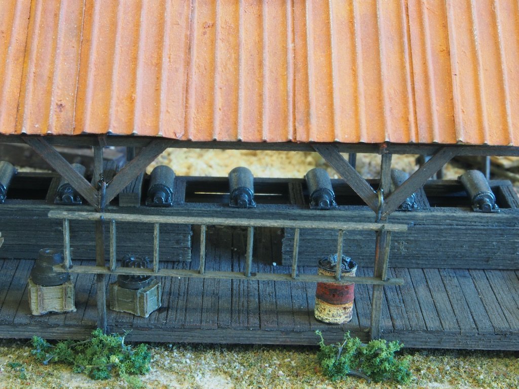
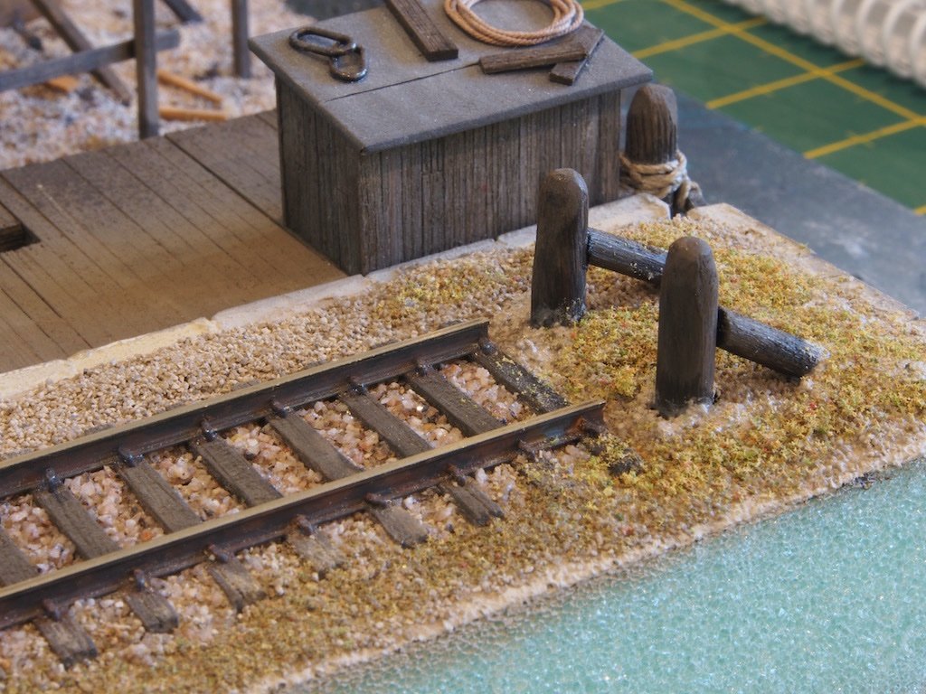
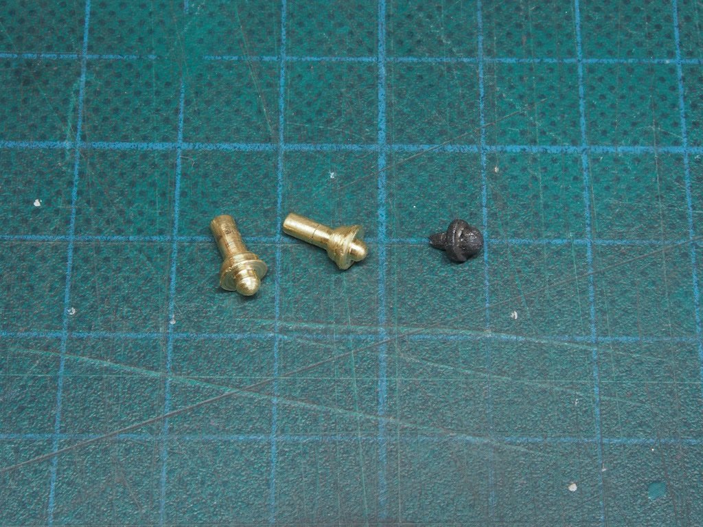
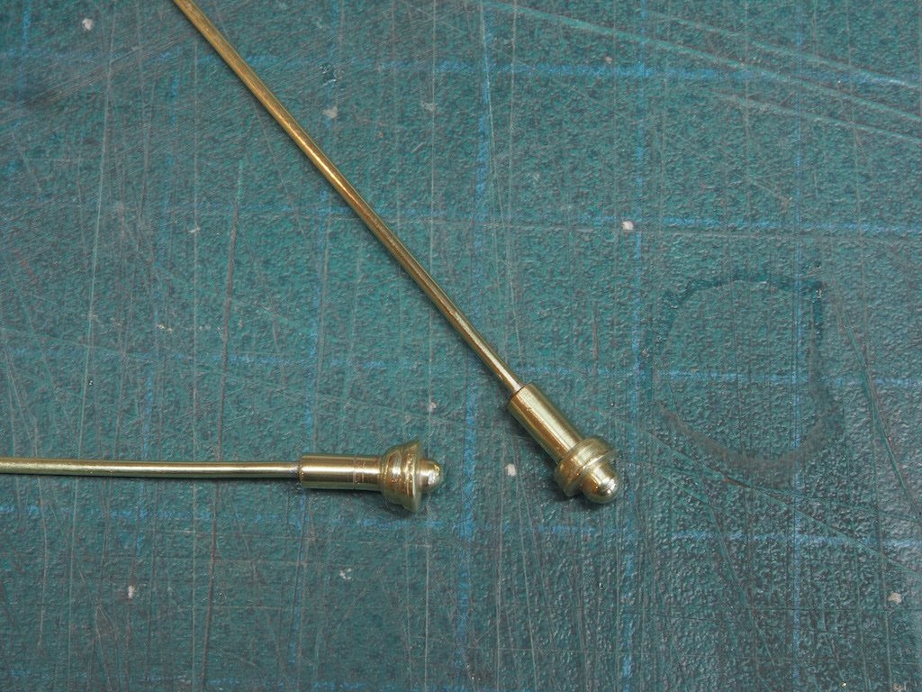
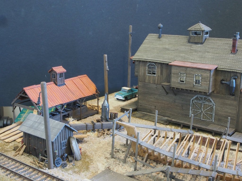
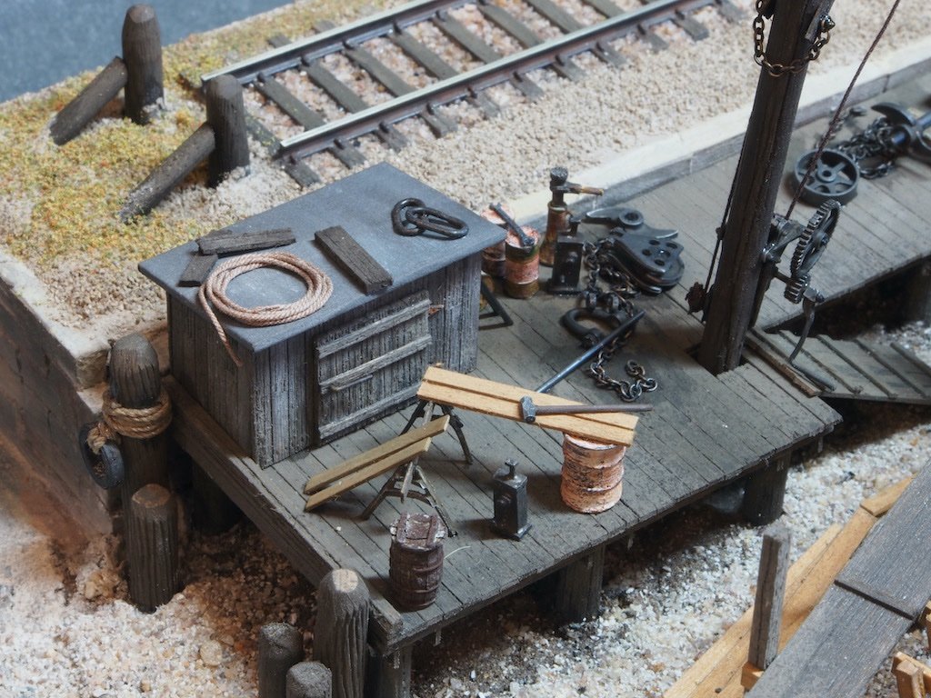
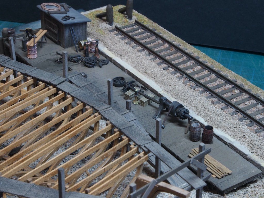
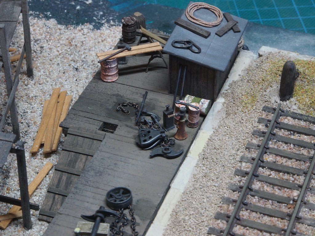
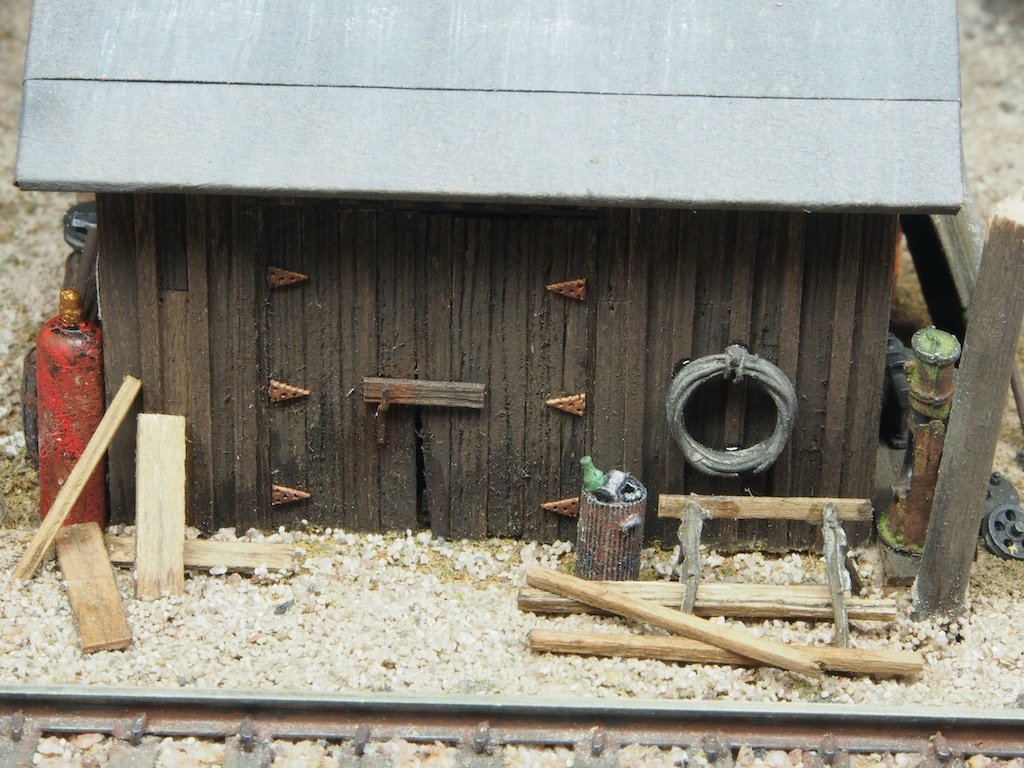
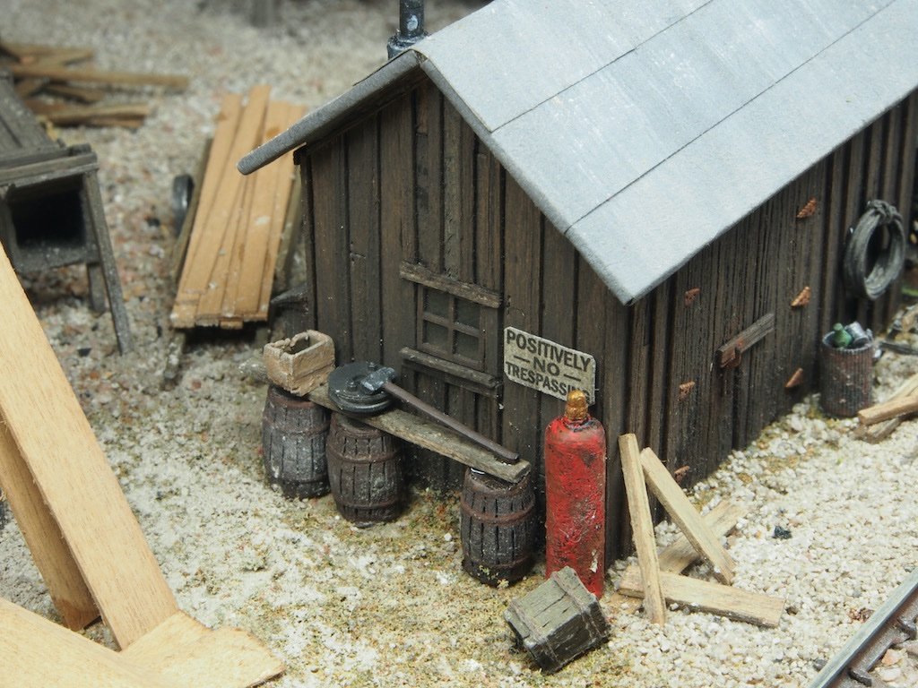
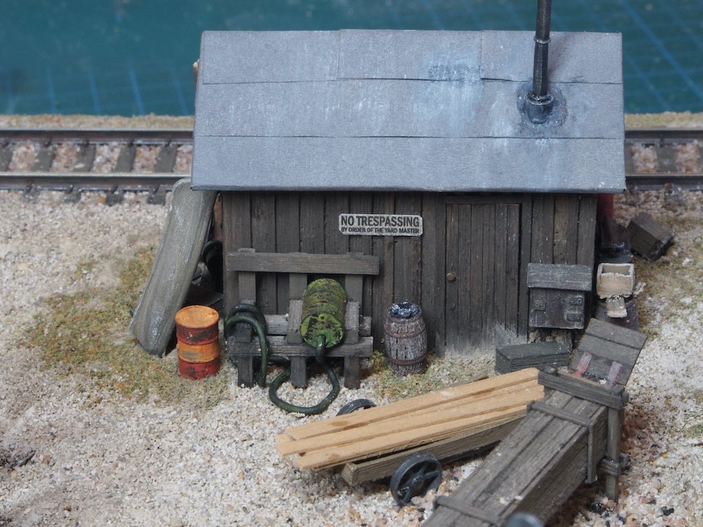
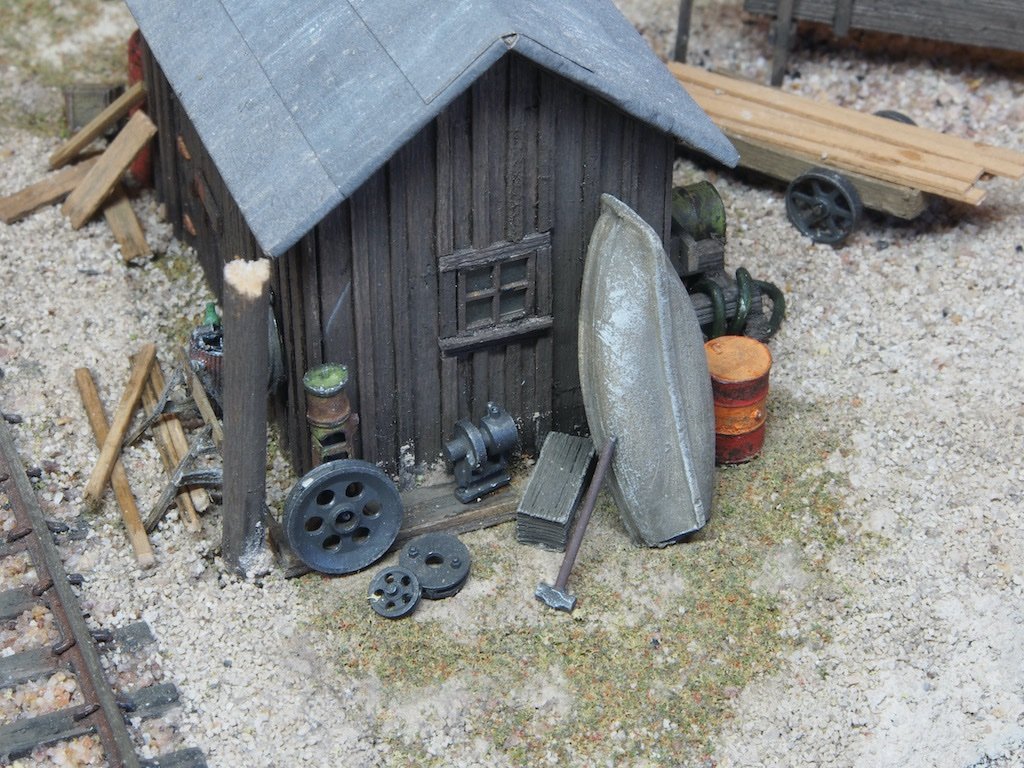
Thanks very much OC, Ken and Mark, and also to all of the "likes". Detailing the Diorama Scenes (continued) A couple of “housekeeping” items to begin with. Firstly, I built an extra ladder and hung it on the side of the Saw Shed using a couple of “S” hooks I made from brass wire. Then the Bumper was added to the end of the rail tracks. This is made from some scrap dowel. Two lamps/lamp posts are required. I found what I believe to be one lamp among the metal castings, but only one. It also requires a piece of brass wire attaching to it to form the lamp post lamp. Faced with the dual problem of being short one lamp and securely fixing wire to a white metal casting, I opted to make a pair of new lamps by turning them from brass rod on my lathe. In the picture below you can see my new lamps on the left, with the blackened original casting on the right. While I was turning these, I also bored out the back end to accept a 1.6 mm (1/16”) diameter brass wire. I then silver soldered the wire to the lamps. Here they are cleaned up and ready for blackening. The lamp posts were made from 7/32” (~5.5mm) diameter dowel. The blackened and buffed lamps were epoxied into holes drilled in the dowel and are shown below temporarily in place in the diorama. (The Telegraph pole can also be seen in the background). In the photograph, the poles look a little over-thick, although in the flesh they seem okay. I don’t know whether this is just a trick of the camera lens, or whether I need to redo the lamp posts. With these tasks complete, I was able to proceed to detailing the Derrick Dock. Here are a series of photographs of the detail in this scene. The end of the dock, with the shed and the Derrick both in place. The Derrick has since been removed for safe keeping until the diorama is complete. An overview from the pit side of the dock (minus Derrick) Looking down at the inboard end of the shed. A closer look at the inner end of the dock. And another view of the shed area. I’ve also done a little more work on the entrance road, adding some hint of vegetation growing between the wheel tracks. It looks like someone has just arrived to check on progress…. The final task for the day was to glue the main building in place. Detailing the various scenes around the main building will commence tomorrow.
- 333 replies
-
- 21
-
-
-
Sorry to hear about the heart attack Michael, but very glad you are now recovered. Even more pleased to see you back at work on your magnificent model.
-
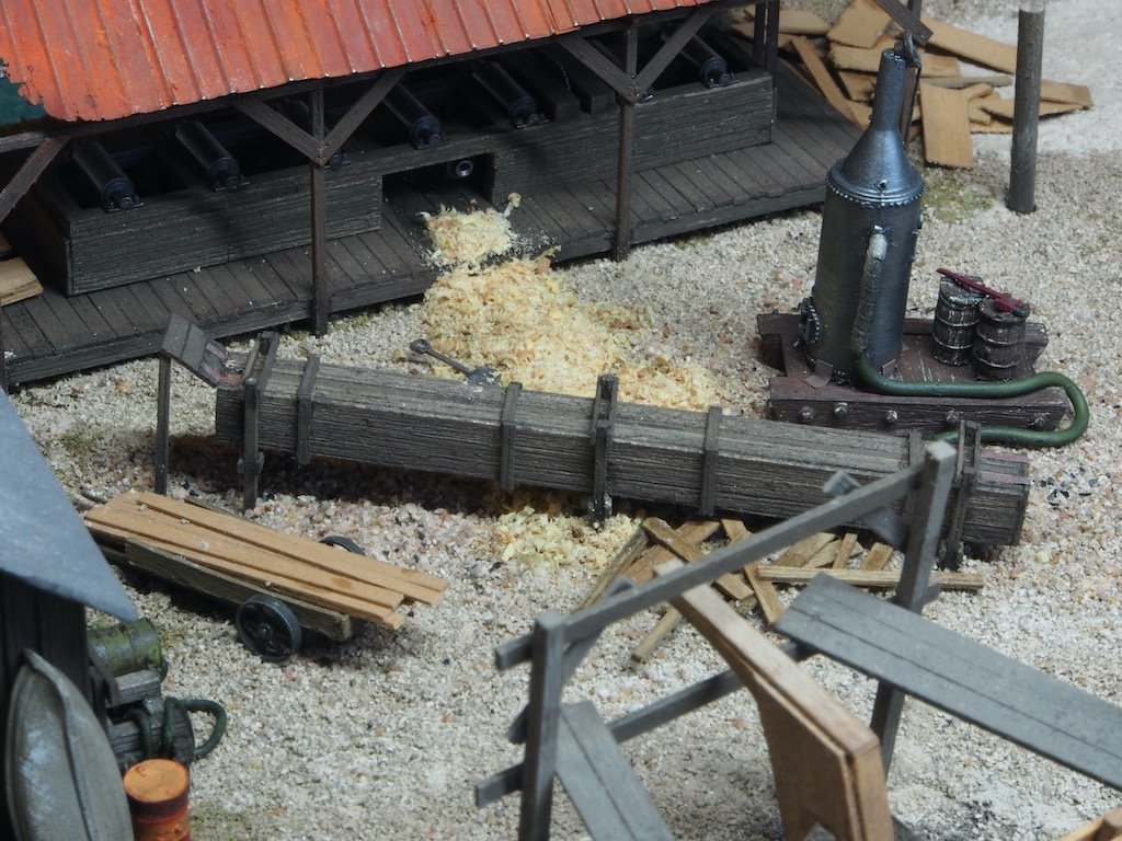
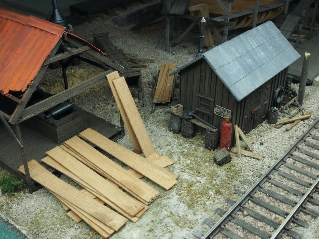
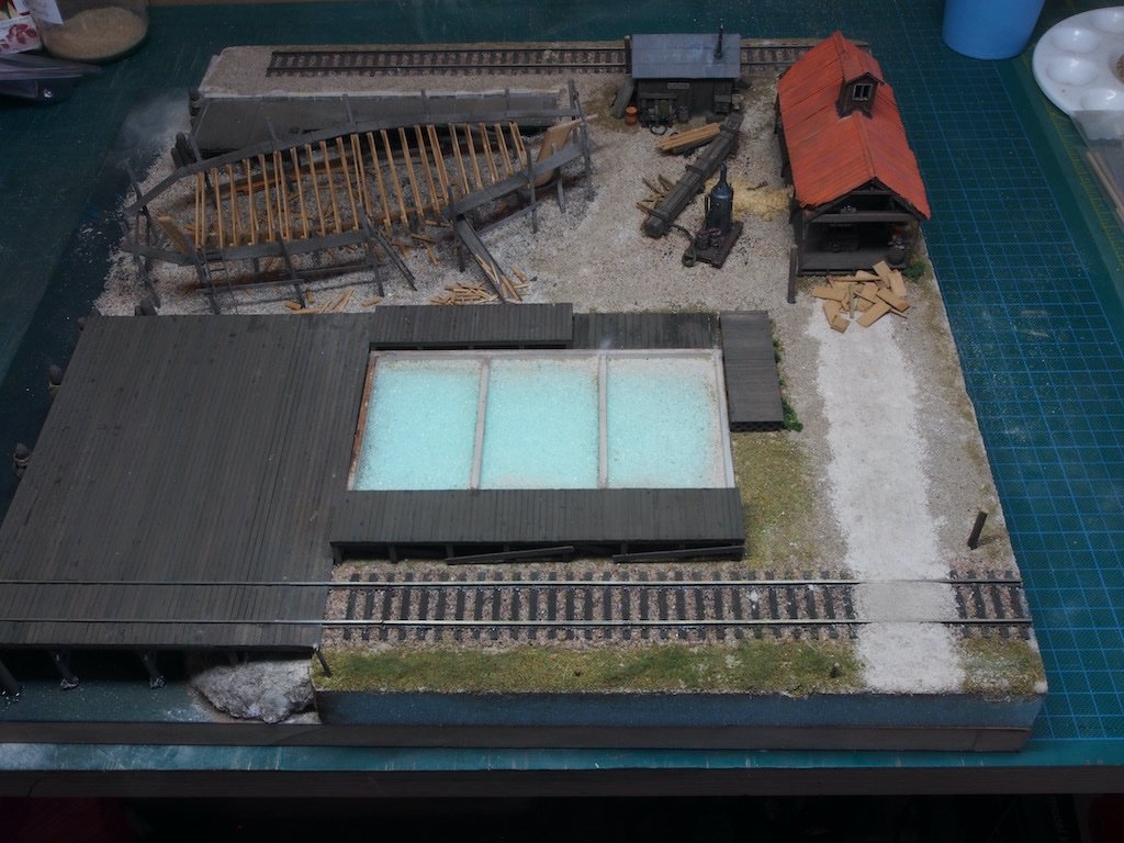
Thanks again for all the encouraging comments and the "likes". Detailing the Diorama Scenes The next task was to add the ballast to the rail tracks. I quickly discovered why most modellers will add the ballast before laying the tracks – it would have been much easier that way! Nevertheless, it didn’t prove to be too difficult. Once the ballast was down, I was able to start adding a secondary layer to the base, including the suggestion of some grass along the outer fence line. (The fence will be added in much later, but for the moment the holes for the fence posts are plugged with some scraps). The loading docks for the main building were also glued in place at this stage. In the picture below, one of the docks is being weighted down while the glue dries. The next task was to create the Steam Box scene. In addition to the placement of the steam box, boiler and hand cart, I added a pile of sawdust that has been created from the blower under the saw table. As this is great fuel for the boiler furnace, a shovel can be seen in the saw dust pile. Several scraps of wood are also scattered about under the steam box. It was then time to place some previously prepared castings around the Upper Yard shed. I struggled with this at first but eventually managed to refine my technique to get the castings embedded in the ground. Here is a series of shots from all four sides of the Upper Yard Shed. The Saw Shed itself was enhanced by the addition of some freshly delivered lumber that has just been unloaded from the rail siding and stacked, ready for processing. The back of the Saw Shed received a few castings, as well as a little shrubbery. The opposite end of the Saw Shed received a few scraps of lumber off-cuts after processing in the shed. In the above picture and the next, you can also see the beginnings of the entry road, which includes creating a crossing for the rail line. There is more work to be done on this. The Derrick Dock will be the next to receive some detailing before the main buildings are placed and the details added around it. Still a long way to go, but I’m fairly happy with progress thus far.
- 333 replies
-
- 15
-
-
-
Thanks Rusty. But be warned, that’s exactly how I ended up with this kit (and another one as well……..) The Sierra West kits really are top notch if you are interested. Just sayin’……………….😉
-
Thanks Roger. No, this will be a stand alone diorama, not part of a layout. At this stage I have no plans to add a locomotive or cars to the track, although that's not set in stone..... I will probably add some HO scale figures, and possibly an old vehicle of some description if I come across something suitable (I'm thinking an old truck......maybe......).
-
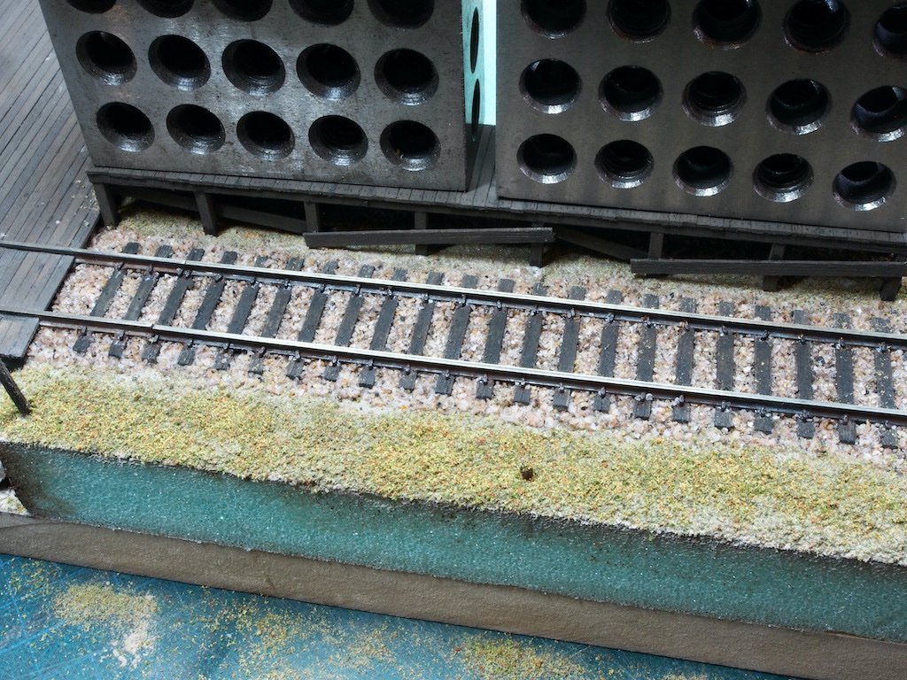
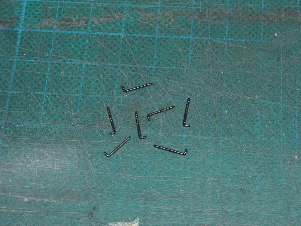
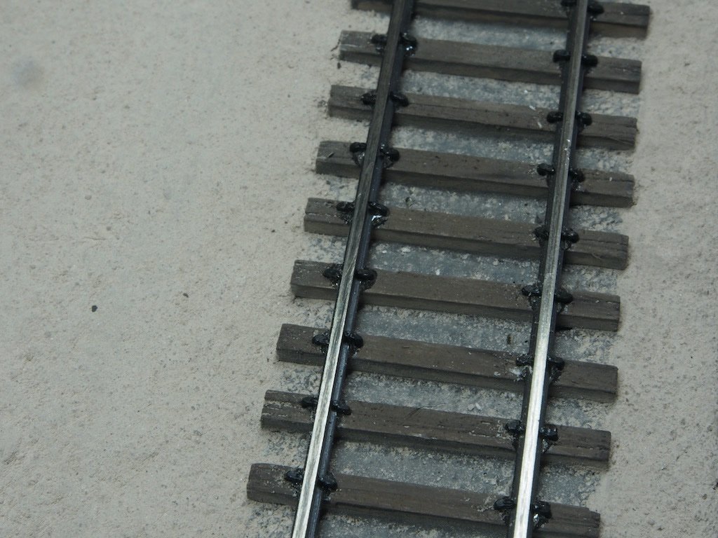
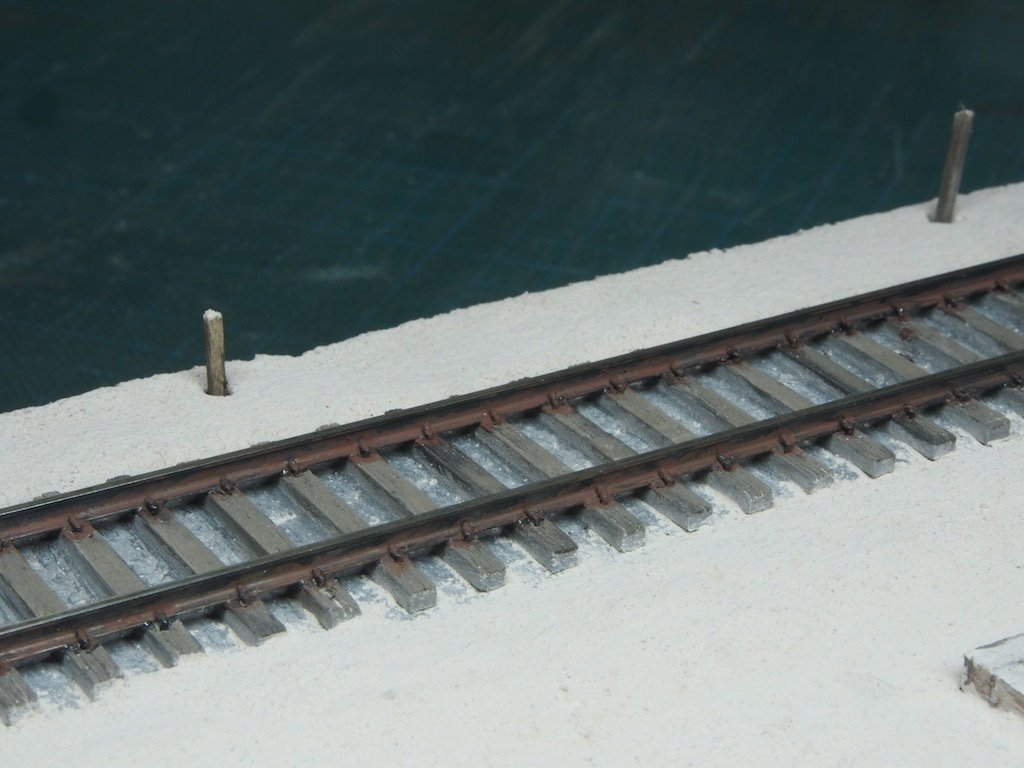
A brief update... Finishing the Diorama Base – Rail Tracks After brushing off the loose “dirt”, I decided that the coverage was insufficient. I painted the surface again, this time with a 50/50 white glue/water mix, and sprinkled on some more “dirt”. Once dry and the excess brushed away, I was much happier with the result. The rail tracks were next. These were first cleaned and blackened using Jax Pewter Black, and then lightly buffed. They were epoxied one rail at a time, with the epoxy left to cure overnight before the next rail was added. An HO rail gauge was used to ensure that the second of each pair of rails was laid at the correct distance. Once all four rails were set up, I added the rail spikes to each tie. The spikes used were Micro Engineering Spikes 30-106, purchased from Fast Tracks at the same time that I bought the rail tracks. They are approximately 8mm (5/16”) long, with a 1.5mm (1/16”) “head”. Here is a picture of the spikes. Although somewhat tedious, pre-drilling for the spikes using a 0.6mm drill made the process go quite quickly. A pair of fine long-nose pliers was all that was needed to drive the spikes. Here is a close-up of a section of track once spiking was complete. And an overview shot at this stage. The sides of the rails, including the spikes, were then painted with a rust coloured chalk/alcohol mix (Rembrandt 411.3). This not only gave a nice rusted appearance to the side of the rails, it also dulled the occasional blob of epoxy. Here is a close-up after the chalk mixture was added. Further work on the scenery base and scenery to follow. The ballast will be added to the rails at some point soon.
- 333 replies
-
- 14
-
-
-
Great work Jeff - it’s coming together very nicely.
