


gjdale
-
Posts
4,894 -
Joined
-
Last visited
Content Type
Profiles
Forums
Gallery
Events
Everything posted by gjdale
-
 Looking good Jeff. I have no idea in answer to your question, but I’m sure the folks over on the SWSM forum will be able to give you some good advice.
 -
Once again I’m late to the party Glen - don’t know how I missed the start of this one! Looks like this will be another very interesting project. You’re off to a great start. And instead of penguins, you can insert miniature chickens! Now there’s a fowl thought……
- 174 replies
-
- 6
-

-

-
- Waa Kaulua
- bottle
- (and 1 more)
-
Your rigging looks fine to me. Your whole model is looking superb.
- 217 replies
-
- 4
-
-
- medway longboat
- Syren Ship Model Company
- (and 1 more)
-
Illness and injury aside Chris, it sounds like a good problem to have! May you continue to have such problems for many years to come. 😊
-
Just thinking out loud here Chuck, but since you have done all of the design work and presumably all of the laser cutting is a “file”, would it not be possible to produce the POF kits “to order”? That would mean that you wouldn’t need to keep an inventory of either kits or raw material in stock until someone placed an order - that order being on the understanding that there would be a certain lead time before the kit was ready for dispatch. And if the cost of materials goes up, then so does the kit price. Just seems to me to be low risk (for you) while providing a degree of certainty for the would-be buyer.
-
Perhaps use a sanding sealer first? That should overcome the issue. A very light sand afterwards will give you a nice base to apply the paint.
- 536 replies
-
- 4
-
-
- Quadrireme
- radio
- (and 1 more)
-
That was my thought too. I hope that is not the case though.
-
Despite some obstacles to overcome Ian, this is still very cool!!!
- 536 replies
-
- 3
-
-

-
- Quadrireme
- radio
- (and 1 more)
-
You’ll be on holiday Chris, but I’ll wager your mind won’t be! By the time you get back there will be ideas/plans for a whole raft of new Vanguard projects and/or tweaks to existing designs and methods.
-
Congratulations on completing yet another outstanding build Glen. I can't wait to see what's next.
- 290 replies
-
- 4
-
-
-
- Quinquereme
- Finished
- (and 1 more)
-
I would not worry about that Glen. It simply shows the tidal range. My advice is to “embrace the creep”.
- 290 replies
-
- 5
-
-
- Quinquereme
- Finished
- (and 1 more)
-
Great job on the water and colour transition Glen. That looks superb.
- 290 replies
-
- 5
-
-
-
- Quinquereme
- Finished
- (and 1 more)
-
Amazing work Ian. Congratulations on achieving a successful first sea trial. I wonder if you really need to increase the oar blade size though - with an extra bank of oars, would the speed actually look about right for the scale?
- 536 replies
-
- 4
-
-
- Quadrireme
- radio
- (and 1 more)
-
Love the cows Glen. Now all you need is to add a BBQ on the grassed area and invite the cows over for dinner………
- 290 replies
-
- 5
-
-
-
- Quinquereme
- Finished
- (and 1 more)
-
Looking good Glen. The texture you added to the timber parts is very convincing. Love the cows - from their colouring, it looks like they may be distant cousins of your penguin colony…….
- 290 replies
-
- 4
-
-
-
- Quinquereme
- Finished
- (and 1 more)
-
Looks great. Congratulations on your retirement - you’ll soon find yourself so busy that you’ll wonder how you ever had time for work!
- 217 replies
-
- 1
-
-
- medway longboat
- Syren Ship Model Company
- (and 1 more)
-
Speaking of Penguins.... I'll get my coat and leave now....

- 290 replies
-
- 8
-
-
- Quinquereme
- Finished
- (and 1 more)
-
Further to Mustafa’s accurate conversions Sjors, I find that a handy approximation to remember is 1/16” = 1.6mm (approx) From there it is easy to work out any other fractional inch (bearing in mind that it is an approximation). So 1/8” is 2 x 1/16” or 2 x 1.6mm = 3.2mm and 1/32” is half of 1/16” or half of 1.6mm = 0.8mm and 1/64” is half of 1/32” or half of 0.8mm = 0.4mm and so on… Hope that is helpful.
-
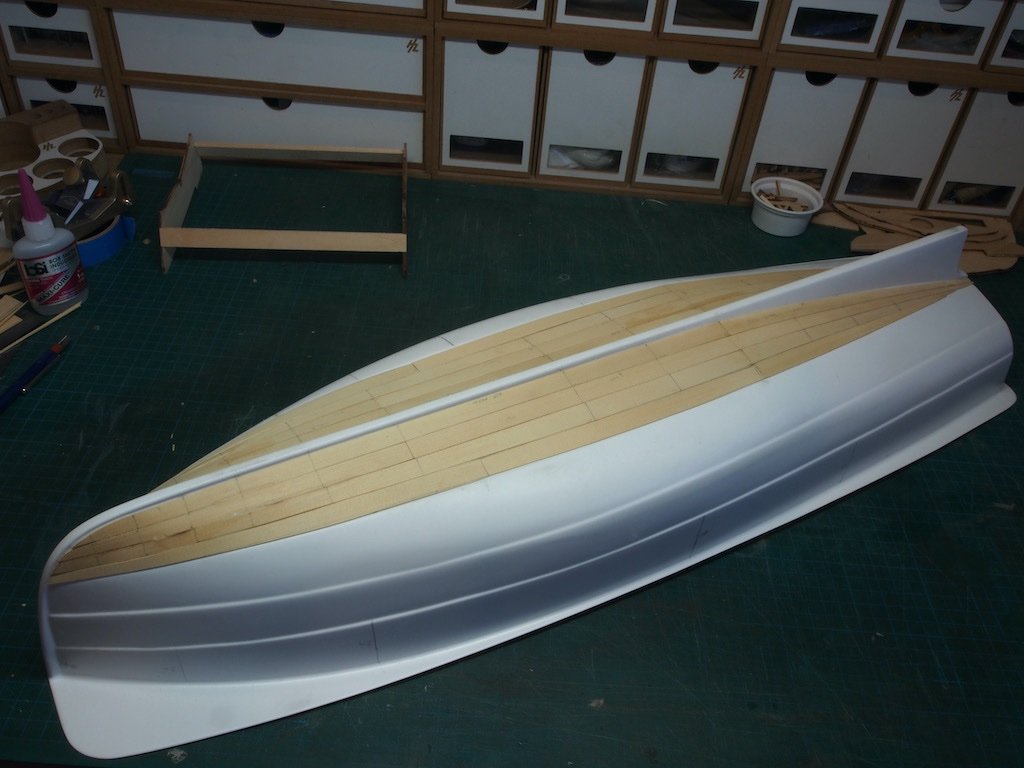
It seems that my modelling mojo has been having a little holiday of late, however there is some progress to report - albeit little more than "proof of life". I have completed the first band of four strakes of planking per side. Three more bands to go, each of three strakes. I will now move my attention to the Sheer strake and work down from there. The trickiest part will be the final band that contains the turn of the bilge.
- 57 replies
-
- 19
-
-
- live steam
- radio
- (and 2 more)
-
WOW! Just watched all the videos Glen. Either you did some serious editing, or the fight wasn’t as close as you say - looks to me like you had this under control pretty much all the way and had a counter move for everything the model tried! Well played Sir! My advice to you now is…..SDH (Start Drinking Heavily)….after all, you need more empty bottles for your next projects.
- 290 replies
-
- 6
-
-
- Quinquereme
- Finished
- (and 1 more)
-
Ingenious solution to joining the hull halves Glen, but then we’d expect no less from you! Can’t wait to see this go into the bottle.
- 290 replies
-
- 6
-
-
-
- Quinquereme
- Finished
- (and 1 more)