


gjdale
-
Posts
4,894 -
Joined
-
Last visited
Content Type
Profiles
Forums
Gallery
Events
Everything posted by gjdale
-
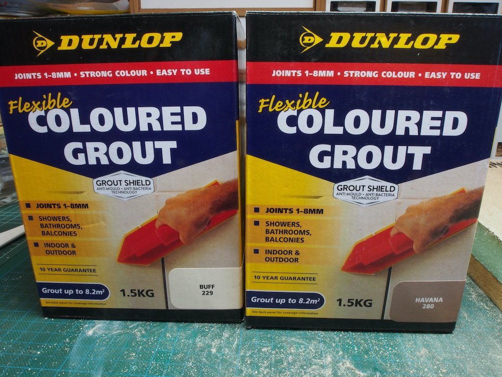
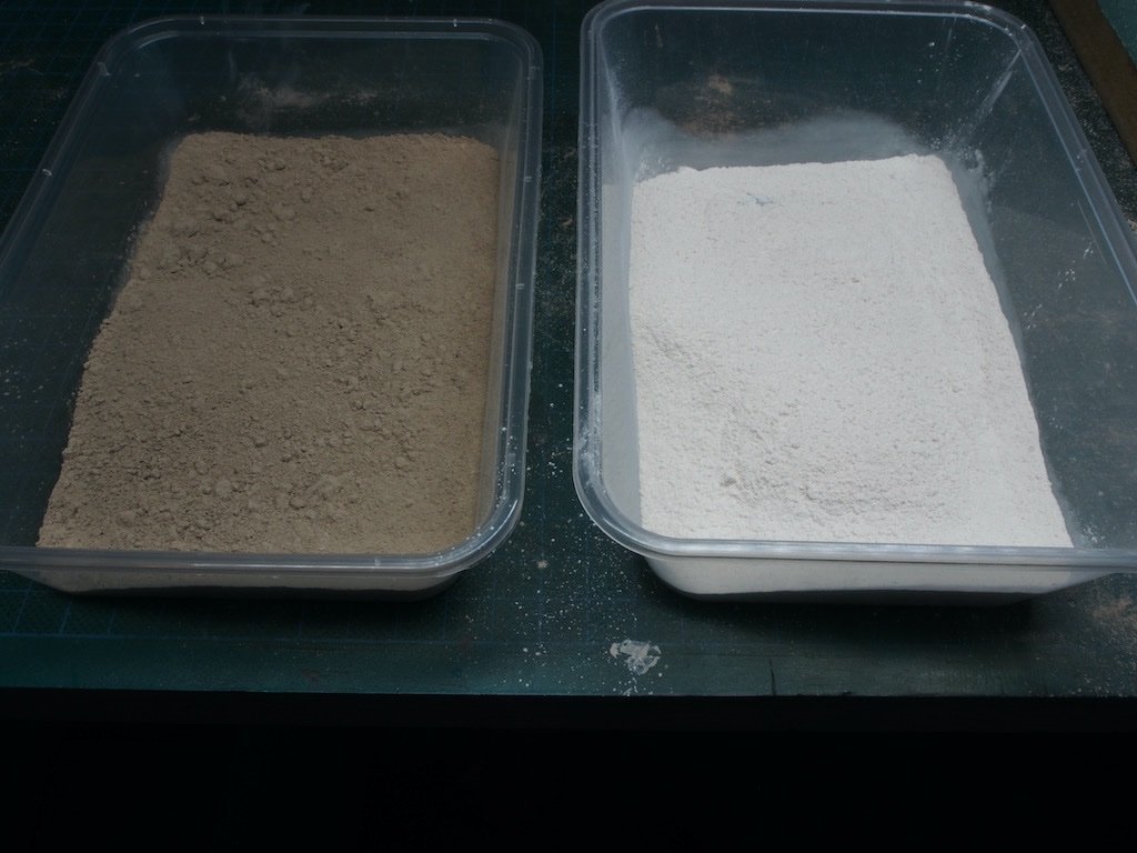
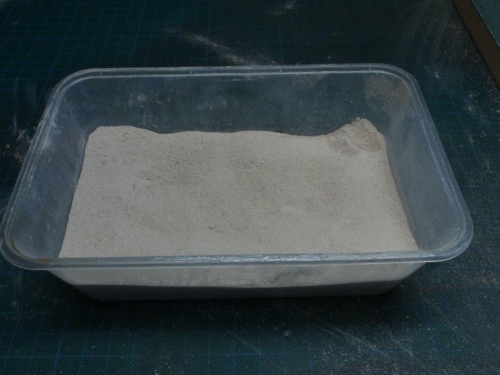
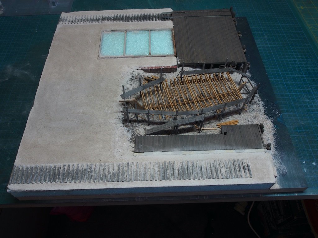
 Thanks Wefalck, Glen, Roger and Keith, and also all of the "likes". A brief update... Finishing the Diorama Base With all the casting details now prepared, it is time to finish preparing the diorama base. This is another trepidatious moment as we are once again venturing into new territory (for me). In addition to the guidance in the instruction manual, I am relying heavily on the excellent discussion threads/tutorials on the SWSM forum by Karl Allison “Dirt, Details & Dioramas”, and Ken Karns “Dr. Grunge...The Dirt on Dirt...(Scenic Work and Sundries)”. While both gentlemen make the disclaimer that this not THE way to do things, it is simply how THEY do things, they both take a similar though not identical approach. I feel in safe hands following their lead. The first step is to put down an initial layer of “dirt”. I’ve followed Karl’s method for this. First up, the necessary materials – some light tan latex house paint and some coloured grout (Karl recommends blending two colours for this step). Both of these were readily available in the local hardware store. A sample pot of paint – with the very helpful colour name of “Cane Chair”. And the coloured grout (a lifetime’s supply!) Here is the actual grout: And once blended, following Karl’s recommendation of one part dark to two parts light. It’s hard to see from the photo, but this blend produced a colour that was almost identical to the paint colour. The base was given a good heavy coat of paint and while still wet the coloured grout “dirt” was sprinkled on and spread with an old paintbrush. I was careful not to get paint/grout onto the ship and pit area but was less concerned about the dock and rail ties as these can be easily cleaned up later. I will leave this to dry overnight before lightly brushing off the excess dirt. Base layer done – breathe….
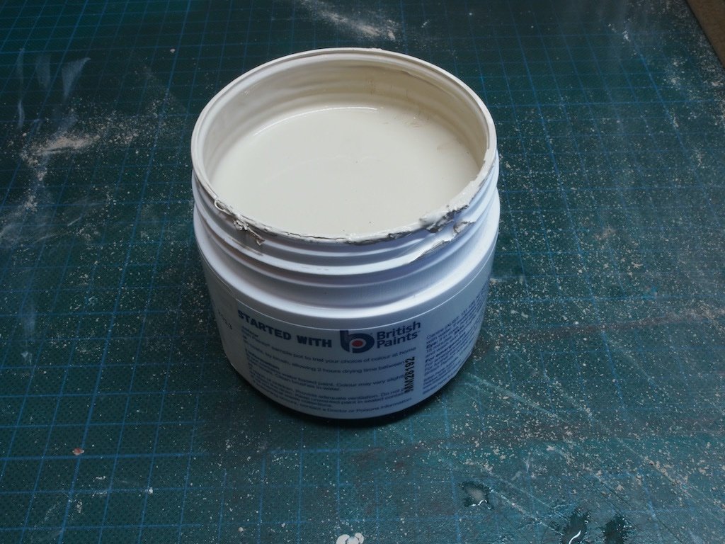
- 333 replies
-
- 14
-

-
I missed the start of this one Nils, so I’ve just caught up. Looks like another interesting build - I’m pulling up a chair.
-
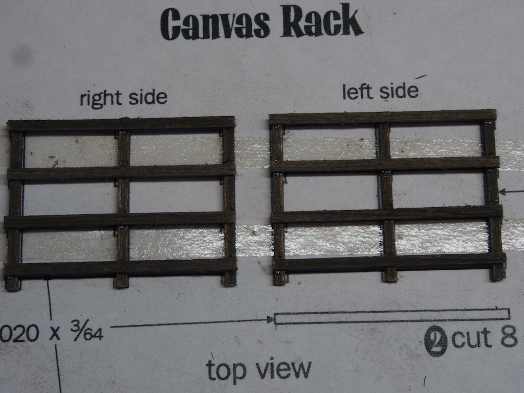
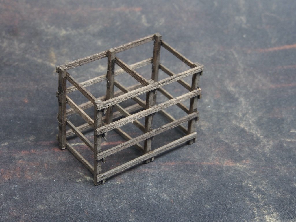
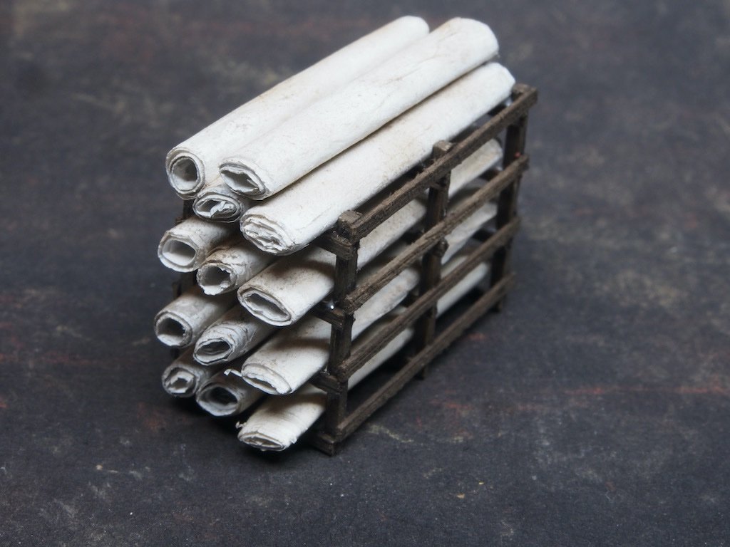
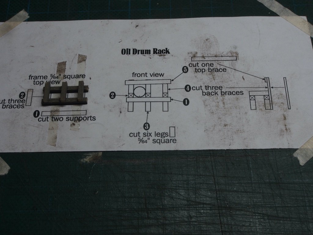
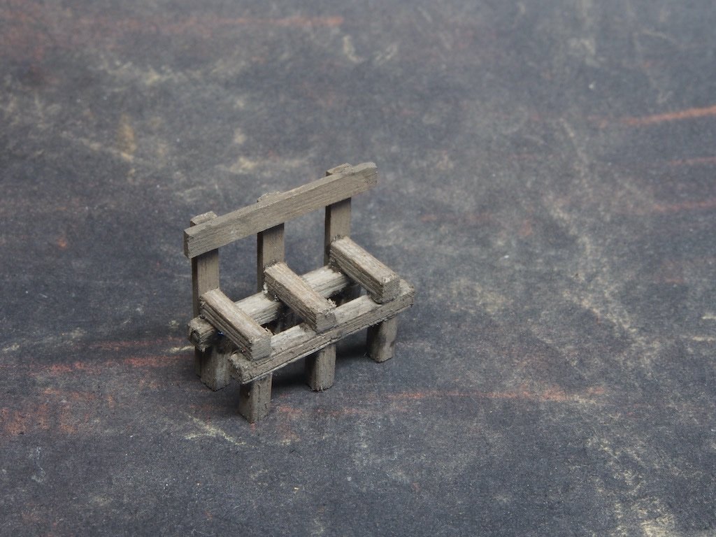
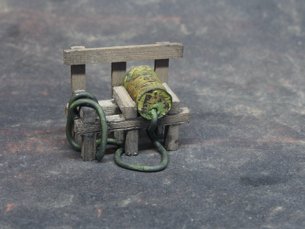
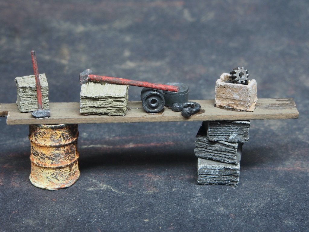
Continued from previous post... A Canvas Rack is built up, once again using the provided template to build directly over. The two sides are then joined by some cross-braces. Rolls of canvas are then made by cutting strips of tissue paper 30mm wide by about 250 long and rolling them around a 3/32” diameter piece of brass rod. The ends are secured with some diluted white PVA glue before the rolls are given a coat of diluted off-white paint and a final dusting of some dry chalk powder. Here is the completed canvas rack. The Oil Drum Rack is built up in a similar fashion. Here is the rack, ready for it’s occupant. A previously prepared drum is then added together with a hose made from 1.0 mm diameter solder wire. A number of “mini scenes” are then created from some of the previously prepared castings and some bits of scrap wood. These will each form part of a larger scene in the final diorama. The extreme close-up of the macro lens shows me that I need to go back and take care of some of the shiny bits of epoxy that are evident here. I believe I am now ready to start adding the details to the diorama itself…
- 333 replies
-
- 15
-

-
-
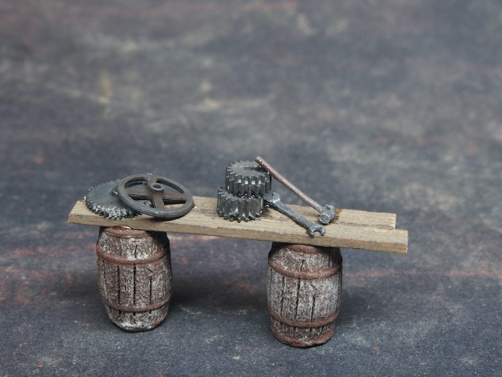
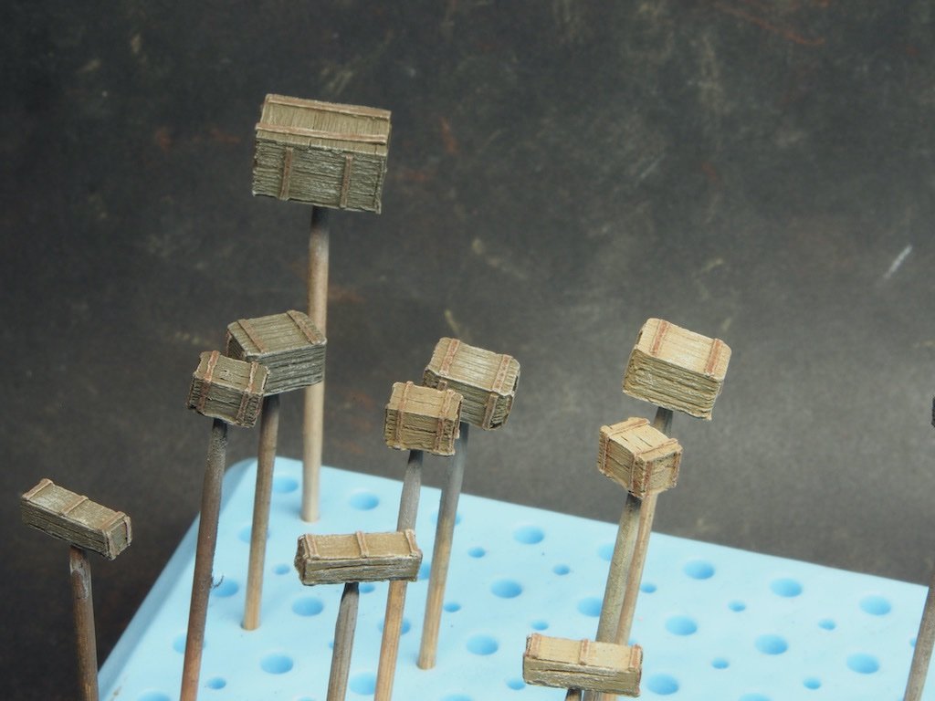
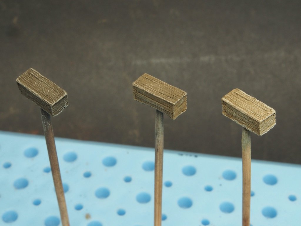
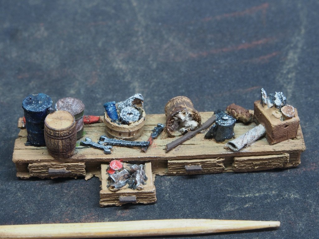
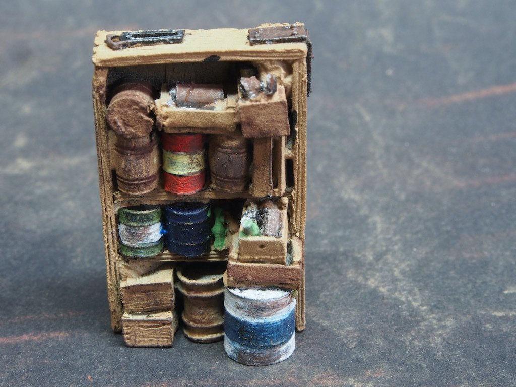
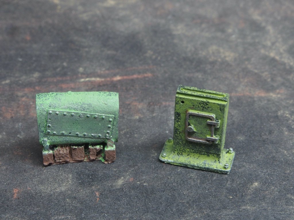
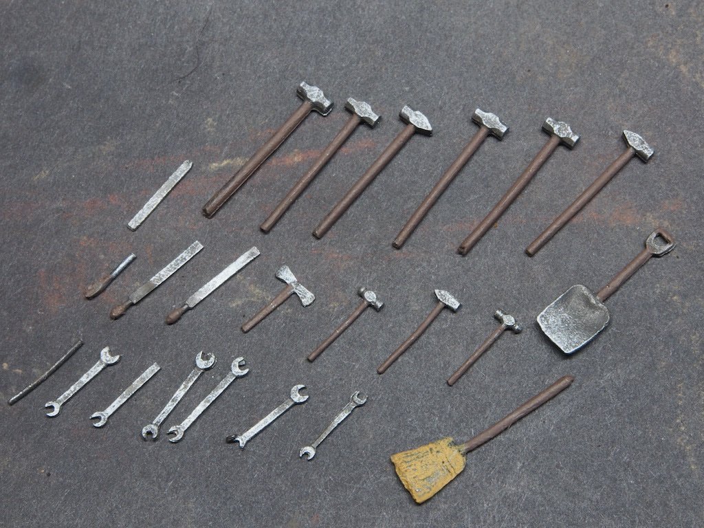
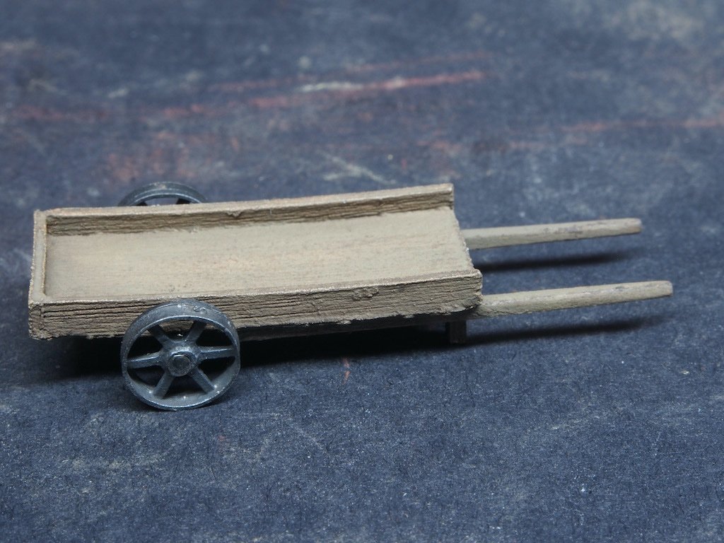
Lots of pictures for this update, so I'll spread it over two posts. The Castings – Painting the Details (continued) I’d been struggling with getting a satisfactory finish on the “wooden” castings, so I posted some pics to the SWSM forum for review/critique/further advice. Here is a selection of crates I posted. Having received some encouraging feedback from the SWSM Forum, I felt confident to continue with painting of the details. I have tried where possible to use some of the techniques explained in a couple of discussion threads on the SWSM forum. We begin with a couple of multi-detailed castings. Here is the workbench top (legs/frame to be added later). This is a single casting, packed with details. I’ve included half of a toothpick in the foreground as a reminder of the scale. Parts were picked out in individual colours and then some edges were highlighted by dry brushing. A little dry chalk powder was added where necessary to dirty things up a little. And here is a cupboard/bookcase, again packed with details. The same techniques were used here. There are a few bins and barrels with the contents cast into them as well. Some miscellaneous larger machinery items – I’m not exactly sure what they are, but figured green was a safe bet for colour. I’ve used a different shade of green on each. Then there are the plethora of individually cast hand tools. These are all cast white metal parts. The metal areas of the tools are left the buffed blackened colour and are then dry brushed to provide some highlights. Subsequent to this photo, I’ve changed some of the wooden tool handles from brown to a peeling red paint. The handcart below is comprised of a resin cast tray, some metal cast wheels placed on a brass rod axle, and some wooden handles made from some scrap strip wood. Continued next post...
- 333 replies
-
- 12
-
-
-
Alfa Romeo Spider Touring Gran Sport by CDW - Pocher - 1:8 Scale
gjdale replied to CDW's topic in Non-ship/categorised builds
I didn’t buy the front axle - I don’t think it’s necessary. I did buy the steering wheel - expensive, but sooooo nice! I also bought a number of the low cost items like spark plug boots and ignition wires. Also the decal set (well worth it). None of them are essential, it’s up to what you think will improve the appearance of your model versus how much you are prepared to spend. It’s easy to get carried away! -
Congratulations on finishing a fine build HOF. Despite the many challenges along the way, you have produced an excellent model - one that you should be rightly proud of.
-
Alfa Romeo Spider Touring Gran Sport by CDW - Pocher - 1:8 Scale
gjdale replied to CDW's topic in Non-ship/categorised builds
The kit instructions are little more than a series of exploded view diagrams. Paul Koo’s instructions take you step by step in a logical sequence and also explain how to do things, as well as giving you a heads-up around some fit issues and how to resolve them. He sells a series of instructional CDs for all of the Pocher kits and the CD contains the written instructions, hundreds of instructional photos of the kit being built, and a stack of reference photos of the real cars. They are a very worthwhile investment. PS There’s a link in my signature block to my build of this kit. You may find that helpful too. -
Alfa Romeo Spider Touring Gran Sport by CDW - Pocher - 1:8 Scale
gjdale replied to CDW's topic in Non-ship/categorised builds
Great to see another of these fantastic models being built. I’m sure that you are aware of some of the fit “issues” with these. If you haven’t already come across him, Paul Koo has produced an excellent set of supplementary instructions that address all of these, along with hundreds of photographs to accompany the “how to” aspects. He also sells replacement parts at very reasonable prices - whatever you are missing, the chances are that Paul will have them. Here’s a link to his eBay store: https://www.ebay.com/str/pocher-philes-forum You can also contact him directly. He is very helpful and easy to deal with. I could not have completed my own version of this kit without Paul’s instructions and replacement parts. Model Motorcars (https://www.modelmotorcars.com/useful-info/favorite-links/) is another great source for “upgraded” parts, but beware - they are not inexpensive, and they are addictive! I look forward to following along with your build.- 51 replies
-
- 11
-

-
-
Thanks Ron - that’s a very nice completed diorama. I hope mine turns out as nicely. I should have a minor update to post this weekend.
- 333 replies
-
- 10
-
-
Congratulations Rusty - a beautiful model, just as we have come to expect from you. It’s been a real pleasure following your build.
- 642 replies
-
- 3
-
-
- winchelsea
- Syren Ship Model Company
- (and 1 more)
-
Master of the understatement!
-
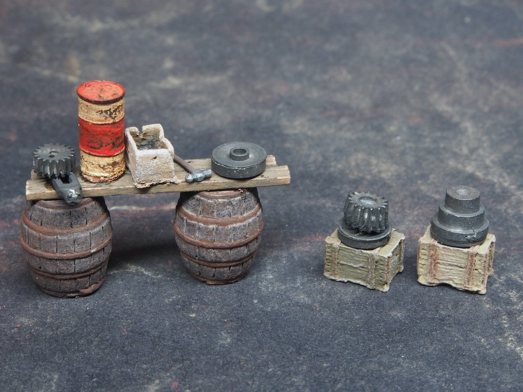
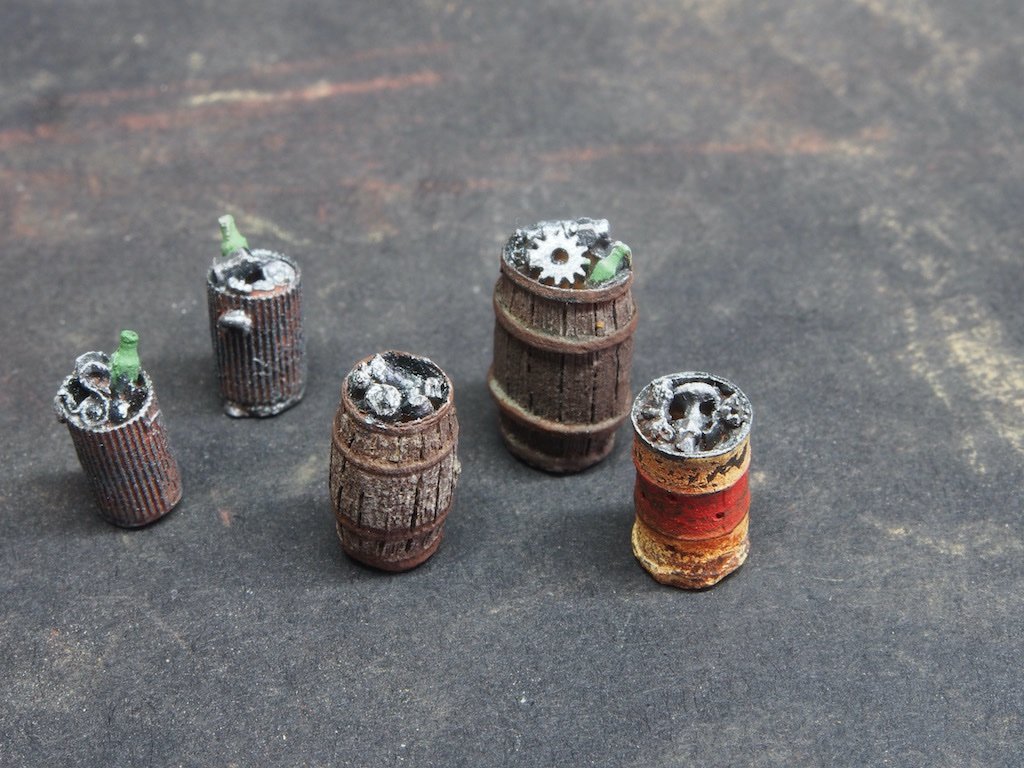
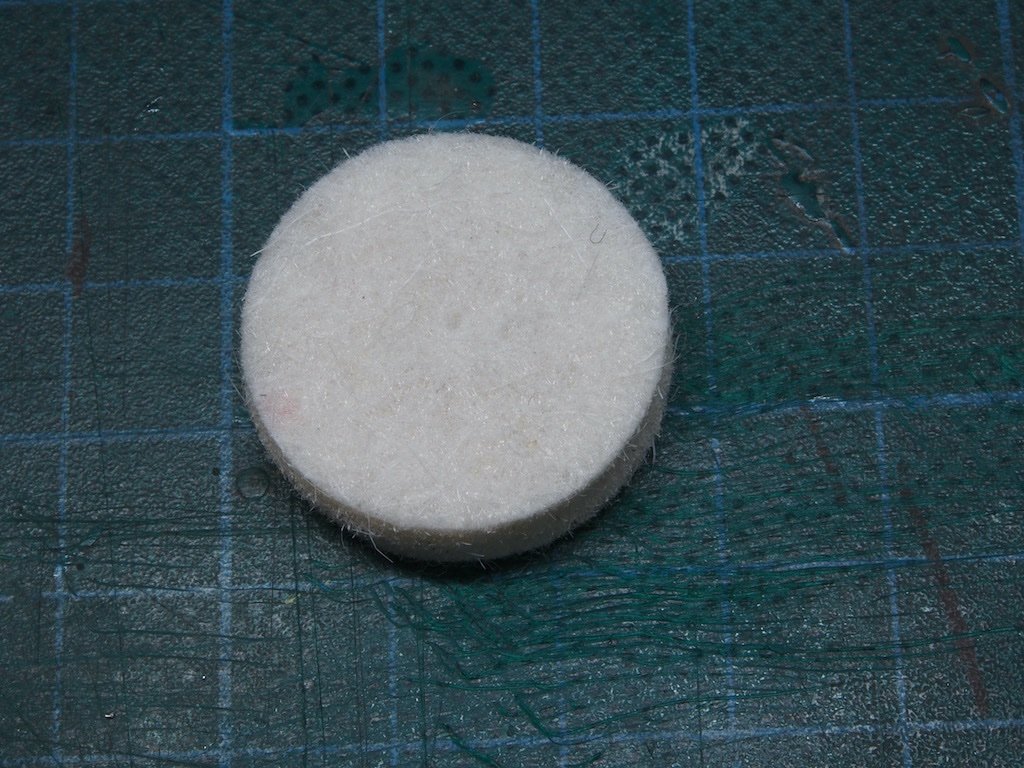
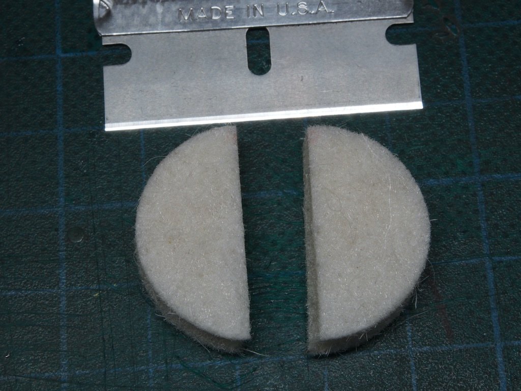
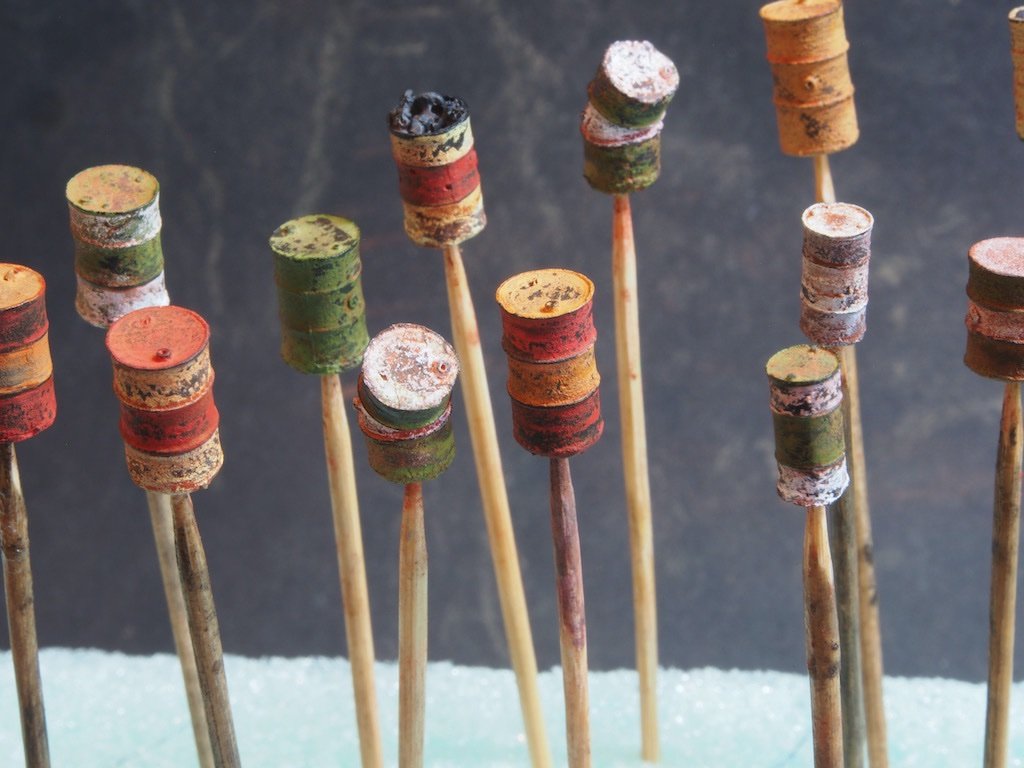
Thanks Egilman for chiming in here - that is exactly correct. But here are some photos, just in case. Take a felt polishing wheel for a Dremel-type tool. Use a single edge razor blade to cut it in half. Now use the semi-circular piece to polish the metal casting BY HAND. These parts were way to small and fragile to go anywhere near a spinning tool. You could attach a handle to it if you wished, as Egilman suggested, but I just held the felt in my fingers. Moving right along... The Castings – Painting the Details There is an excellent video tutorial on the Sierra West Scale Models website that demonstrates an extremely easy, yet highly effective technique for achieving peeling and chipped paint effects on the castings. In summary, Once the base coat of black has been allowed to dry thoroughly (in my case it was left for a couple of days), colour is applied using a selection of AK paint colours, and while still wet the part is dunked in Isopropyl Alcohol (IPA) and then dabbed with a make-up sponge to randomly remove bits of paint. It is left to dry for at least a couple of hours, and then the process repeated if there is a second colour to be added. Once that has also dried thoroughly, the parts are dusted with various rust-coloured chalk powders and given another dunk and swirl in IPA to remove most but not all of the chalk, and left to dry again. That’s it – process complete. Here are some of the resin cast oil drums – I have yet to paint the details of the contents of the one in the centre at the back. The process works equally well on the metal castings of the Acetylene Tanks. Back to painting wooden crates……..
- 333 replies
-
- 14
-
-
-
Thanks Bob, To answer your question, it gives you a semi-circular shape which simply gives you more options on which part of the felt to use. If you need a sharp corner to get into a crevice, then you have one, as well as both a straight section and a rounded section. No photo to hand, but I think you can get the idea?
-
I think you mean "gateway drug" Hamilton. Beware, these things are extremely addictive! Before you know it you'll be mainlining with a Mill as well.
-
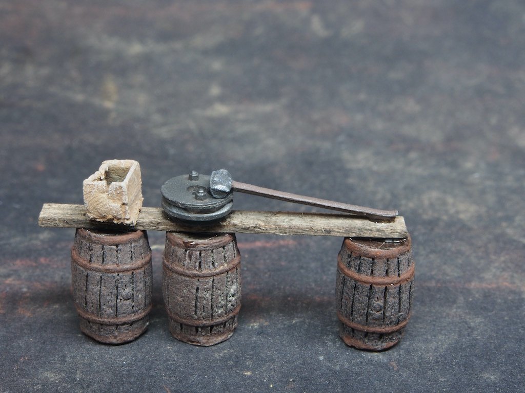
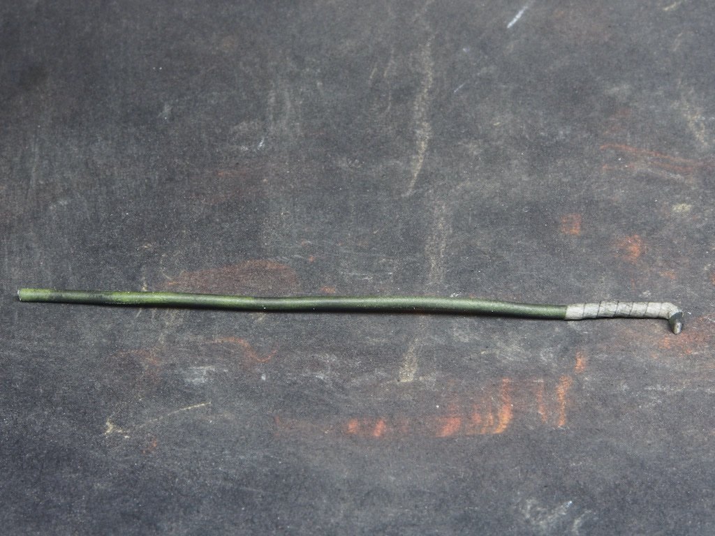
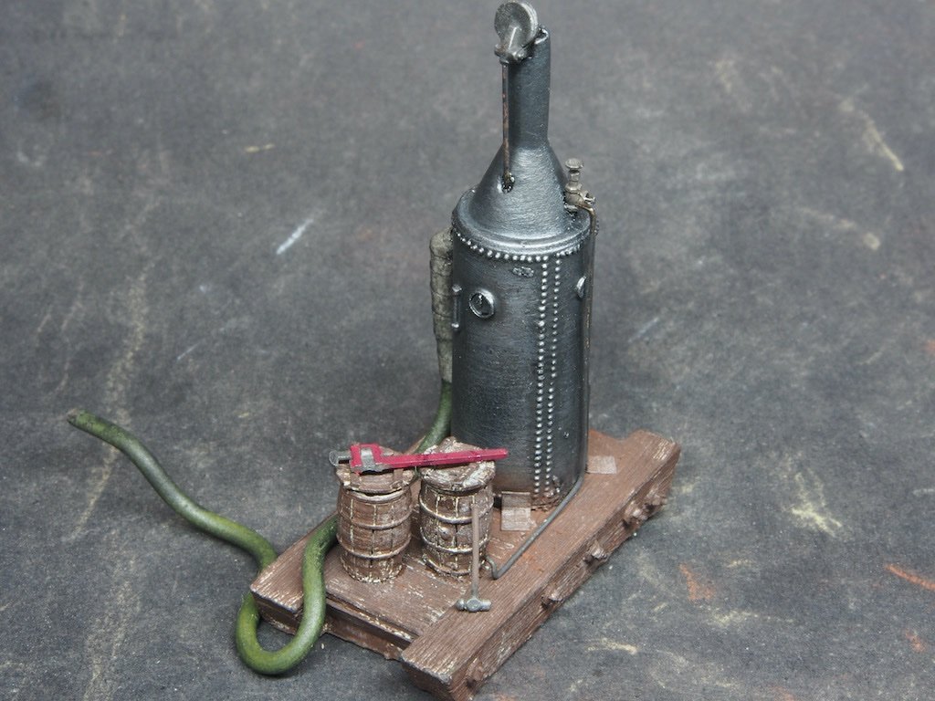
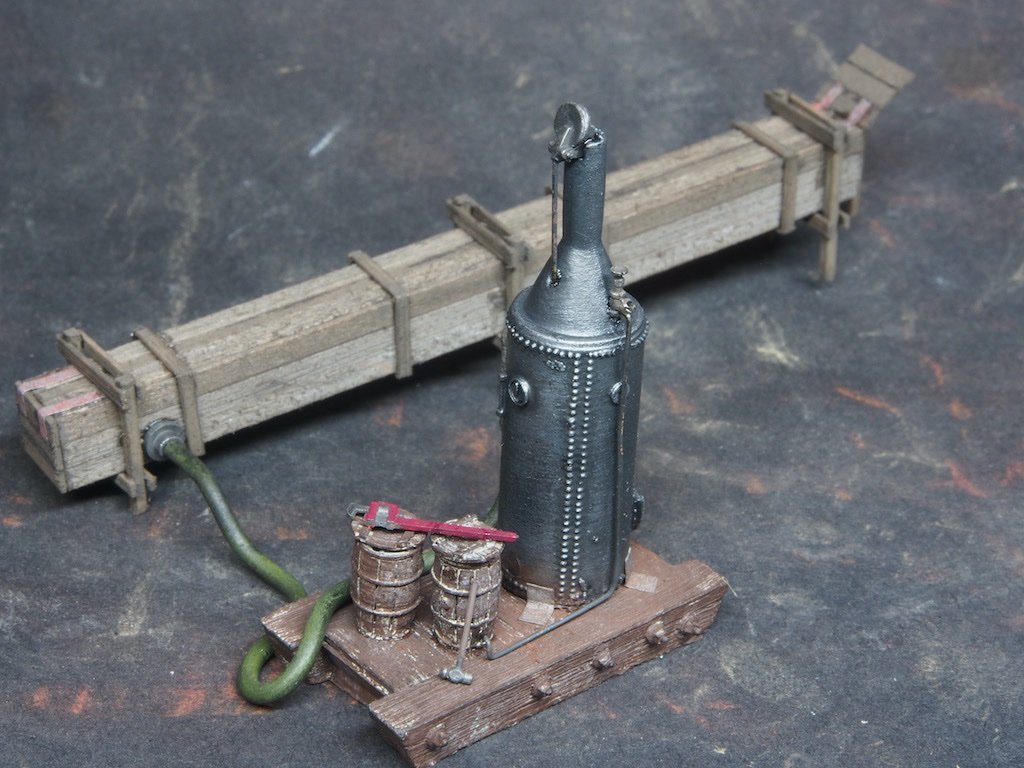
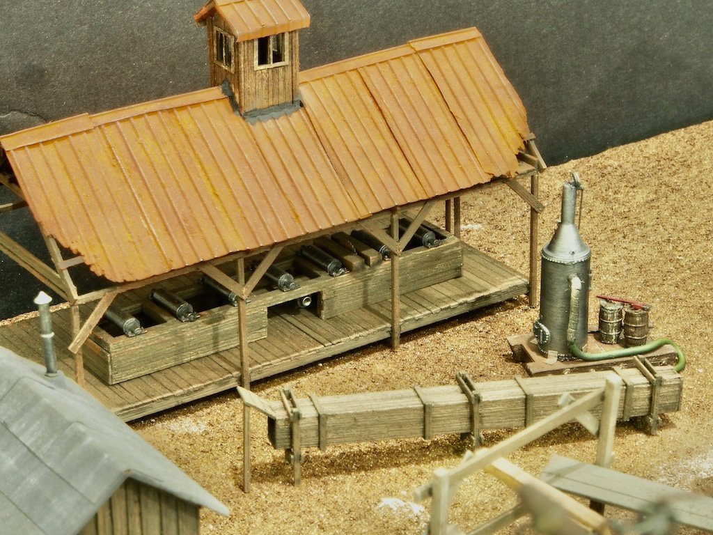
The Boiler With all the castings now having their initial preparation complete, it was time to turn attention back to completion of the Boiler for the Steam Box. The boiler itself is a resin casting, but it has a white metal casting Stack Cap and Valve, along with a brass wire Stack Wire. The boiler was painted with AK 11212 (Gun Metal) and then dry brushed with AK 11210 (Natural Steel) before the blackened and buffed metal parts were epoxied in place. The boiler is mounted on a wooden sled – another resin casting. This was first painted with AK11008 (Grimy Grey) and then dry brushed with AK11110 (Leather Brown). A couple of the tiny hand tools had their handles painted - AK11095 (Dirty Red) for the large wrench, and AK11110(Leather Brown) for the wooden handle of the hammer. In the photo below, you can see part of the toothpick that the sled is mounted on for painting. Two barrels are given the same treatment as the sled (again mounted on toothpicks here). A Steam Hose is then made from a three-inch length of 1.2mm diameter solder. It is painted with AK11147 (Olive Green) and one end is then wrapped in masking tape to simulate the lagging. It was then dirtied up with light dusting of (dry) black and grey chalk powders. The boiler was then epoxied in place on the sled and four “supports” were made from paper, painted with AK11210 (Natural Steel) and then dusted with some (dry) rust coloured chalk powder. The barrels were then epoxied in place and once dry the feed-water pipe was made from some 0.5mm diameter brass wire, blackened and buffed, and epoxied in place between the barrel and the valve on the boiler. The two hand tools were then epoxied in place, and finally the steam hose was epoxied in place on the side of the boiler. Here it is with the steam hose temporarily attached to the steam box. Finally, here it is temporarily in place on the diorama. I had to play with some post-processing adjustments on the photo as the original was very dark. More details will be added to this scene later. Now it’s back to painting all of those casting detail. This could take a while….
- 333 replies
-
- 24
-
-
-
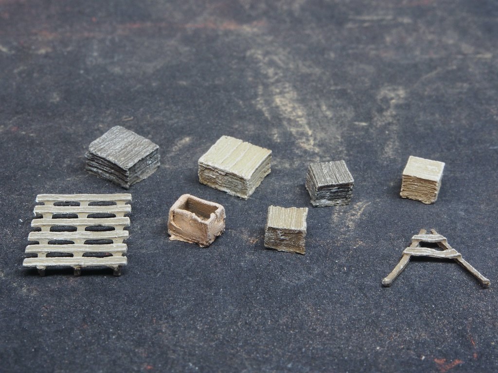
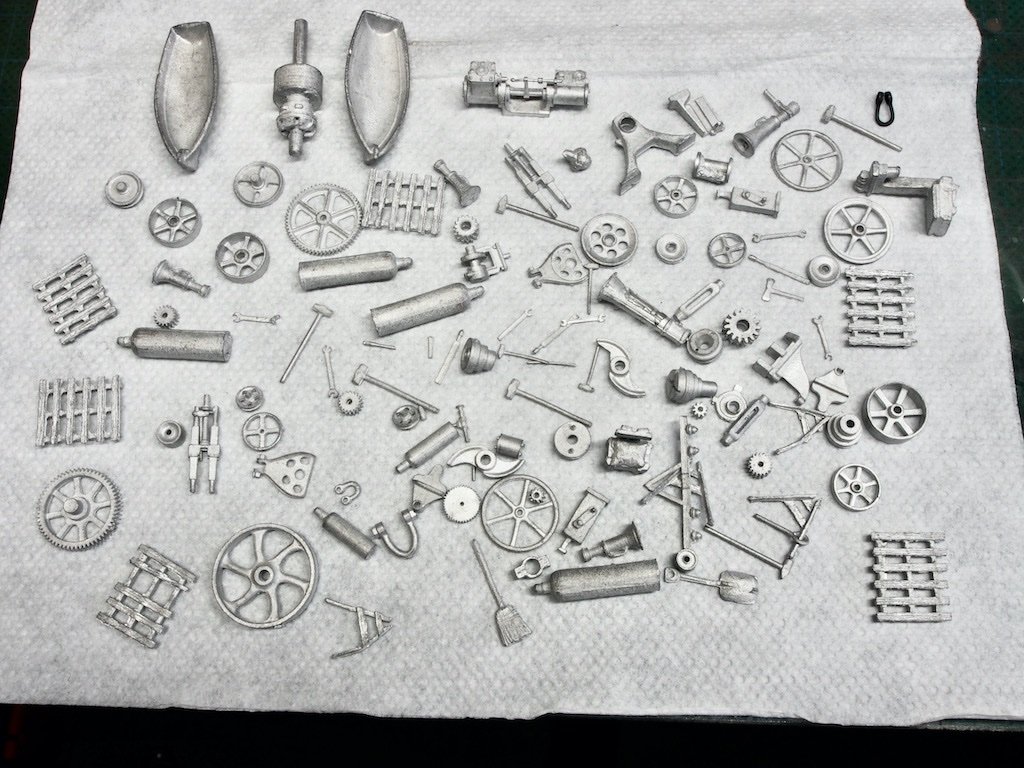
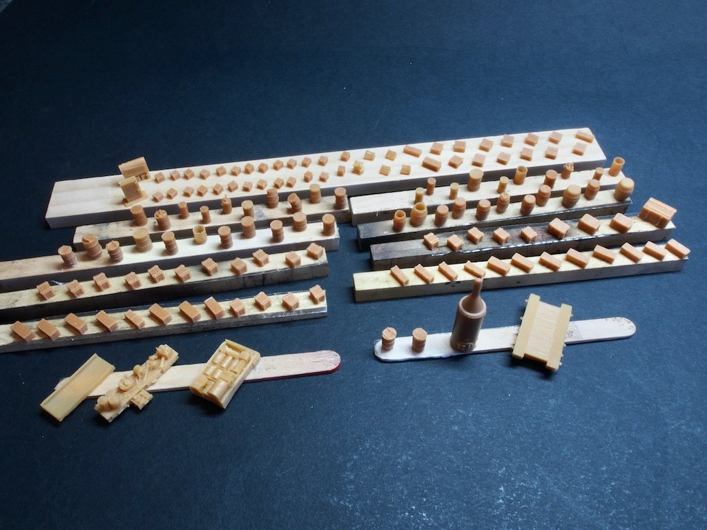
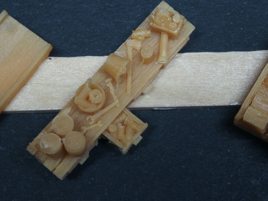
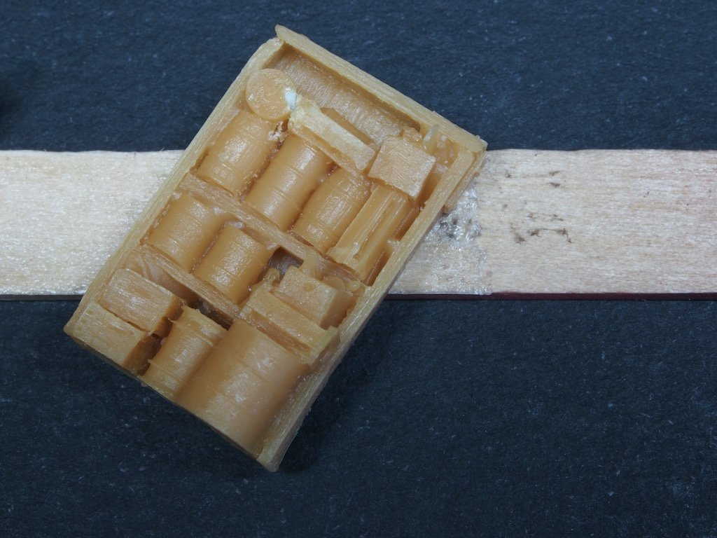
The Castings There are a great many castings included in this kit, in a mixture of white metal and resin. They all need preparation, so I decided that now was as good a time as any to do the initial preparation. Along the way I decided to count them… Including the few castings that are already in place, there are a total of 174 white metal castings and 147 resin castings. Here is a shot of the remaining white metal castings prior to being “processed”. Some of these parts are extremely small, especially the hand tools! My “process” for the preparation of these parts is to first wash them all in slightly soapy water, then rinse. Next up is an Acetone bath, after which they are not handled by bare hands again. A quick rinse in distilled water, then a 20-minute soak in Vinegar. Another rinse off in distilled water then left to dry before application of Jax’s Pewter Black, applied by scrubbing the part with an old paint brush. Once the part is totally blackened it is dipped in distilled water again and then left to dry. Finally, all parts are gently buffed by hand using a felt wheel from a Dremel that has been cut in half (a tip I picked up from the kit designer). That took a couple of afternoons work to achieve. The resin castings get a scrub in some soapy water and then rinsed. They are then prepared for a base coat by attaching them to various scrap wood “handles” using double-sided tape. Here is an overview of all the resin parts ready for spraying. While most of the resin castings are individual parts, there are a couple of composite castings that pack in an incredible amount of detail – especially when one remembers the size of these. For reference, the castings in the foreground of the above picture are mounted on popsicle sticks. Here is a close-up of the casting of the work bench top (centre casting on the left popsicle stick). Note the open drawer full of “stuff” as well as the clutter on the bench top. And here is the open cupboard right next to it. Some of the barrels and bins are also filled with incredibly details parts, like this barrel full of spare/discarded parts. Although some of the tutorials suggest that castings representing metal should be sprayed black and those representing wood should be sprayed a “wood” colour initially, the kit designer in his own tutorial suggest spraying all parts black initially, regardless. I took that advice and sprayed all of these parts with Stynlyrez Black Primer using my airbrush. Another afternoon’s work….
- 333 replies
-
- 16
-
-
-
Looks like it all worked out in the end Tim, but I don’t know why you shied away from using fibreglass. I too was terrified when I first used it, but by following the advice I found on another site (RC Groups), I found it was actually quite easy. It might have actually saved you some time/effort. But, all is well that ends well as the saying goes. 🙂
-
Just a thought Keith, but rather than printing across many small sheets and having to stick them together (with inherent risks to accuracy), why not take your PDF to a local plans printing shop and ask them to print on a large format paper? I don’t think the cost would be prohibitive, particularly taking the benefit into consideration.
-
Just stumbled across your log here Keith. What a beautiful and interesting subject you have chosen! I’m pulling up a chair and will follow along from here.
-
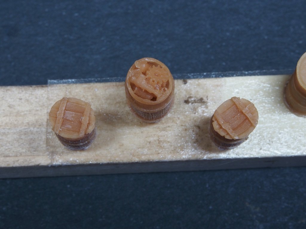
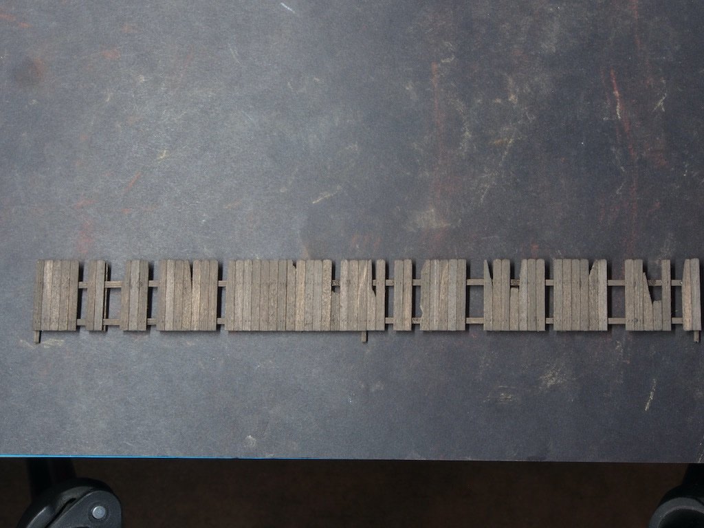
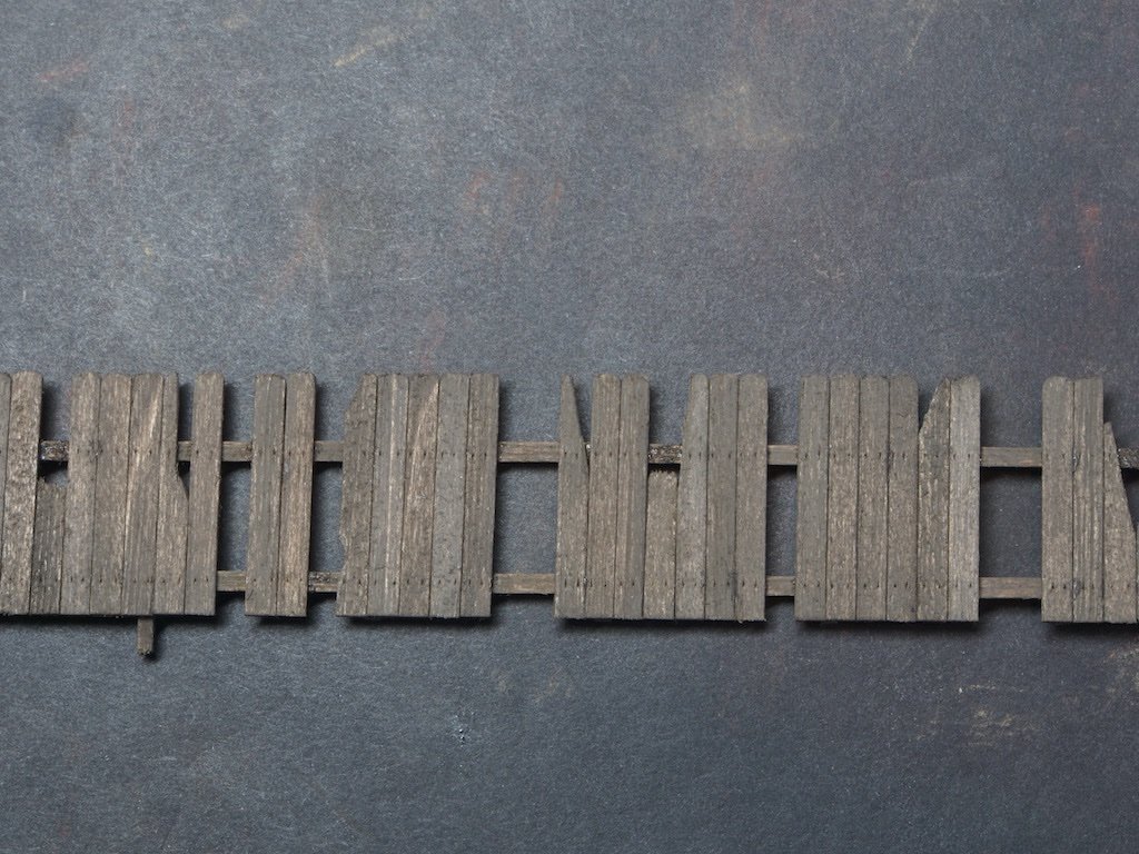
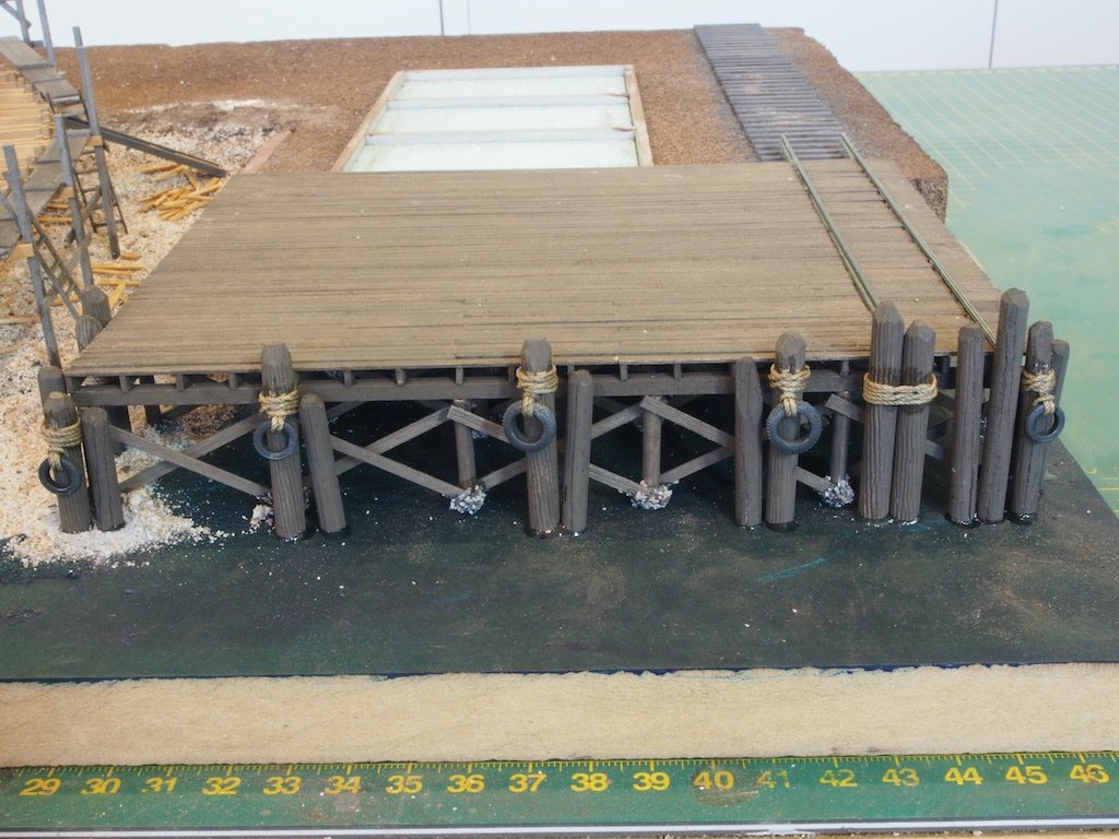
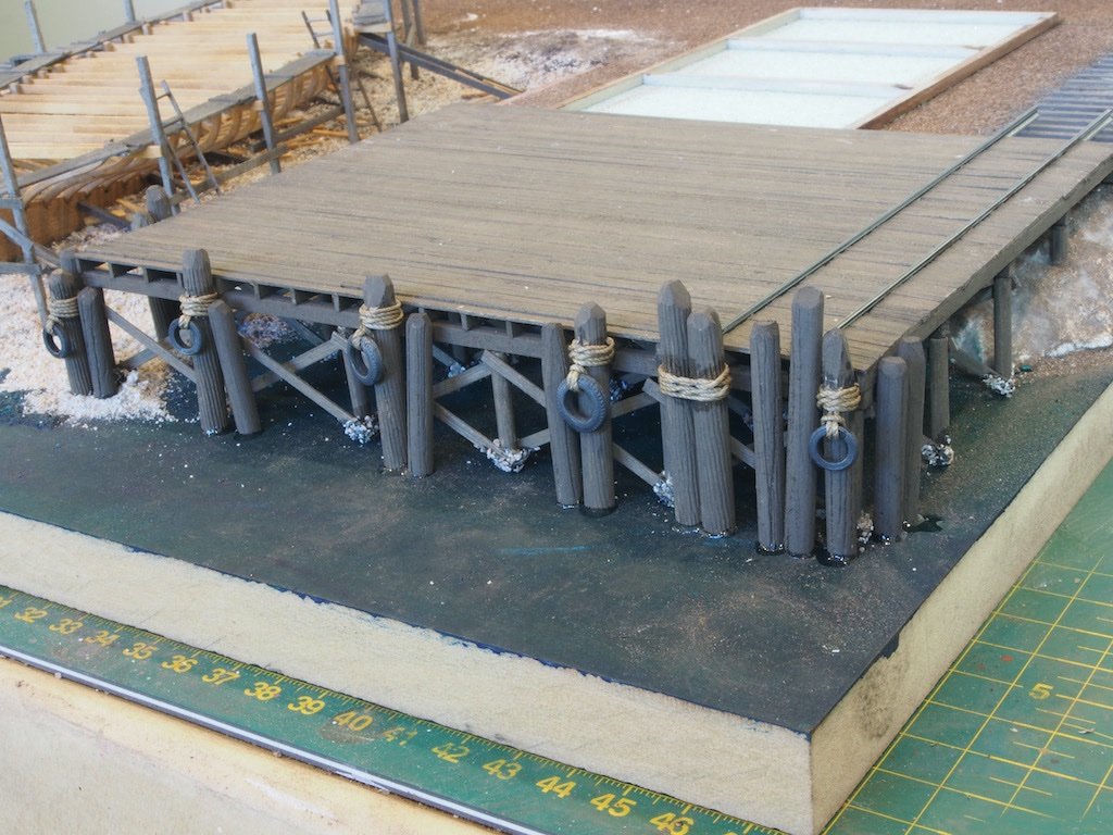
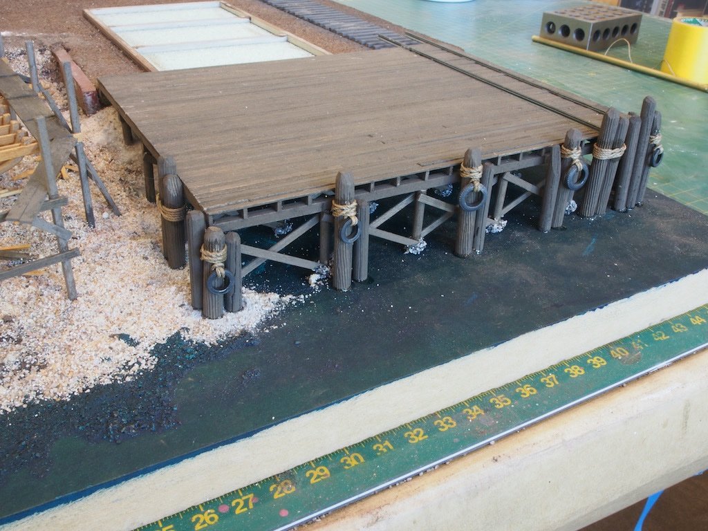
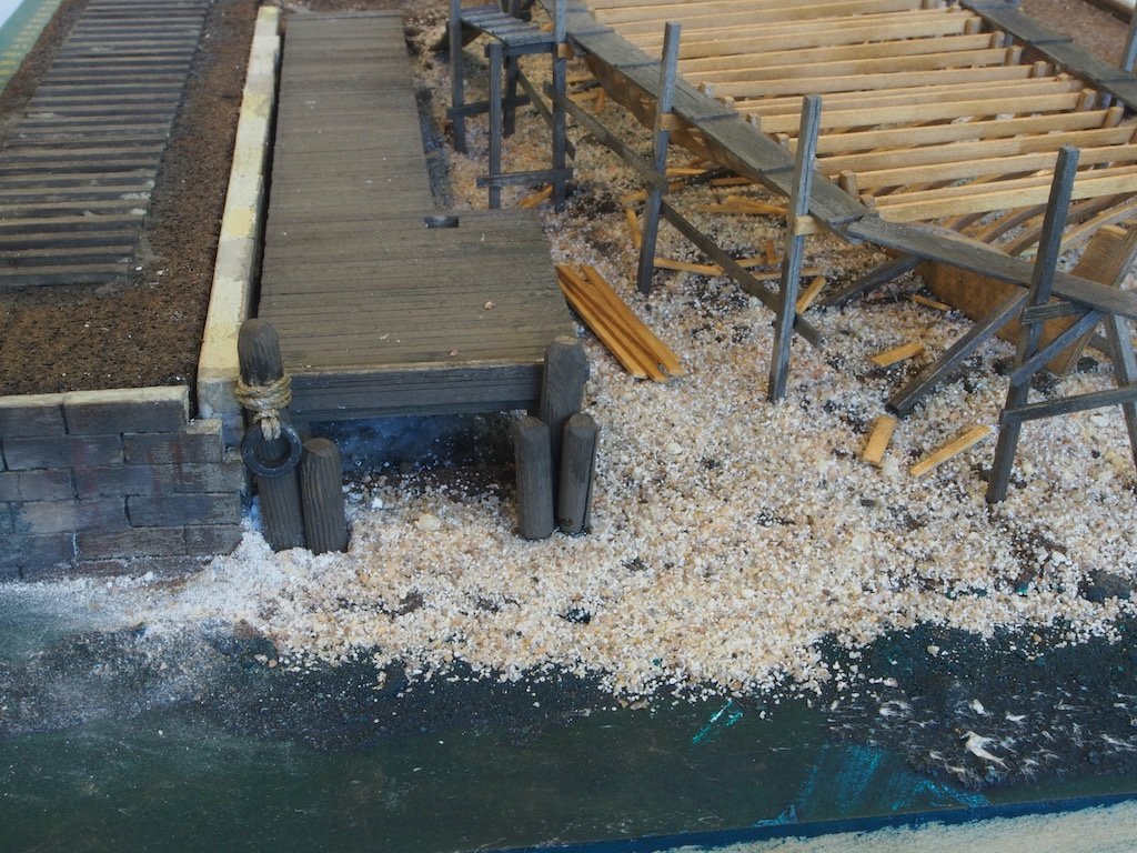
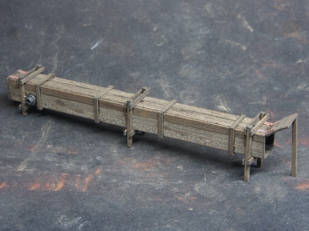
A minor update... The Wooden Fence As the kit instructions remind us, fences create a barrier that allows us to define a scene. This is a simple board on board construction using the provided template to define the overall dimensions and placement of key components – the posts and rails. The posts are made from 3/64” square stripwood, and the rails from 0.020” x 1/16” strips. Individual boards of 0.02” x 3/32” are then applied after applying plenty of texture, splits and cracks. I forgot to take any in-progress photos, but here are a couple of completed shots. Overall view. And a close-up of the mid-section. The fence is now set aside for later placement on the diorama. The Bumper Pilings The bumper pilings are made from dowels. Unfortunately, there did not seem to be enough dowel of the right diameter (3/16”) provided in the kit to complete this task, so I supplemented the kit stock with some from my own stash. The latter were slightly larger in diameter and of a much harder wood. The harder wood made imparting grain much harder, and for this I used the edge of a saw blade for an exacto knife. Tyres are provided in the form of white metal castings which are blackened, buffed, painted and chalked before being attached. I did not like the look of the provided cotton string, and there was not enough for the task anyway, so again I substituted from my own stash for this. Again, I did not take any in-progress shots, so here are a few of the completed pilings. I tried to follow as closely as possible the distribution/layout shown in the example in the instruction manual, including deliberately leaning some of them. The main dock pilings. And the Barge Derrick Dock. The Steam Box The steam box was used for softening the planking, making it easier to bend to attach to the hull. Steam from the boiler was pumped into the steam box and a little while later, it was ready to go. This provides an excellent opportunity for creating a scene that tells a story within a story. The actual construction of the steam box is very straight forward with a solid core of ¼” square stock being clad in some .020” x 3/32” stripwood and 0.020” x 1/16” stripwood. Wrap braces are made from more of the 0.020” x 1/16” stripwood and applied. Finally, the legs and braces are made up from 3/64” square strips for the legs and 0.020” x 3/32” strips for the braces. Thin paper strips are used to create the hinges on the doors and a small white metal cast hose ring / inlet is blackened and buffed before being epoxied in place. Again, no in-progress shots, but here is the completed Steam Box – 3 ½” in overall length. Next up will be the boiler to accompany the Steam Box.
- 333 replies
-
- 20
-
-
-
Thanks for that excellent explanation Elmer - that all makes perfect sense to me. 🙂
-
The chain is to prevent the presumably removable through-pin from working its way out. I do agree though that there might be more rigging/support required - especially if the mast is able to rotate (which I think it must do).
-
The jib is held to the mast by a through-pin. In this case, the modelling simplification is to use two short pins instead of one through-pin. Other than that, I can’t say - it’s just the way the kit is designed.