Ian_Grant
-
Posts
2,156 -
Joined
-
Last visited
Content Type
Profiles
Forums
Gallery
Events
Everything posted by Ian_Grant
-
 Bill, I agree that the ratlines look better darker. What did you do to stain them? Reading Kirill's recipe I wonder if it would affect the longevity of the thread as a display?
- 1,508 replies
-
- 1
-

-
- Le Soleil Royal
- Heller
- (and 1 more)
-
Looks like a great planking job to me, especially for such a voluptuous hull!
-
Harriet McGregor by Boccherini
Ian_Grant replied to Boccherini's topic in - Build logs for subjects built 1851 - 1900
Beautiful work. -
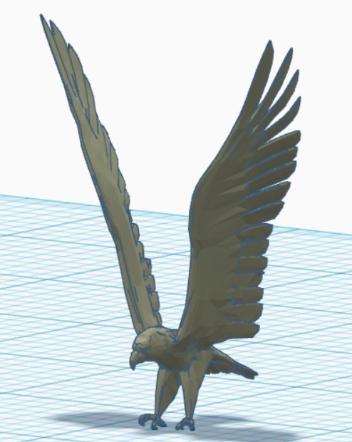
Yet another post on 3D eagles. Found a likely-looking one for the bow, with wings spread. I measured in TinkerCAD and his wings are at too narrow an angle compared to the bows, so as an experiment I will try a PLA print at the library; if successful some surgery will be in order to see how he looks mounted. If nice, I can get a resin print later or possibly play around in TinkerCAD to amputate his wings and re-attach at a wider angle.
- 536 replies
-
- 5
-
-
- Quadrireme
- radio
- (and 1 more)
-
Interesting looking ship; I also do not think she is ugly. But 30kg!! That's a heavy RC model to lug to water........🏋️♀️
-
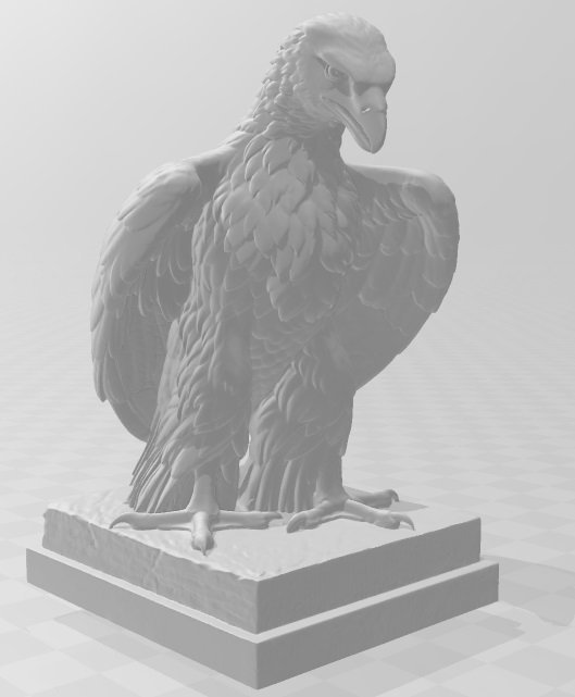
Success! Scaled to 3/4" tall, pedestal removed (with a few lingering glitches in his tail feathers) in TinkerCAD. Shall see if Andrew can clench his claws for me, to go around a cross-bar on the stern flagpole. Many thanks to Paul!!
- 536 replies
-
- 4
-
-
- Quadrireme
- radio
- (and 1 more)
-
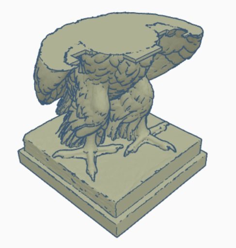
Paul, I did so and here is what was imported into TinkerCAD......HaHa!! I'm guessing this massive model exceeded the z-axis limit in TinkerCAD. Will try scaling it in 3d builder then re-importing.
- 536 replies
-
- 4
-
-

-
- Quadrireme
- radio
- (and 1 more)
-
When I get to the point of needing a crew I'm hoping to visit him for a weekend for a tutorial on using blender to pose figures. I have bookmarked a 3D legionnaire figure who is "fully rigged" meaning he has "bones" which can be moved around to pose him, and his armour/clothing just sort of flows naturally as posed. Would beat amputations and re-gluing.
- 536 replies
-
- 2
-
-
- Quadrireme
- radio
- (and 1 more)
-
Thanks Paul. Apologies for wasting your time, but it wasn't from thingiverse after all; I was all over the web looking and I downloaded that eagle from myminifactory. How many 3D model sites are there I wonder? Here's a try at attaching the actual .stl file......Needs to be simplified down to 25M, don't know what it would like by then. Perhaps it would be simplest (for me) if I sent the file to my brother who presumably is familiar with better tools than TinkerCAD which is the extent of my 3D skills. https://www.myminifactory.com/object/3d-print-jupiter-as-an-eagle-from-the-ganymede-group-a44-278554 thorvaldsen-a44-a-eagle.stl
- 536 replies
-
- 2
-
-
- Quadrireme
- radio
- (and 1 more)
-
Bill, you need to decide what ropes go to the kevels. The main braces absolutely do not tie off at the flagpole and should go to a kevel. I believe there is a kevel on each side which Heller leaves unused. Re-assign the kevels in a way that makes sense. Someone else's SR log mentioned this, I forget whose. Good luck Mr. Phelps.
- 1,508 replies
-
- 1
-
-
- Le Soleil Royal
- Heller
- (and 1 more)
-
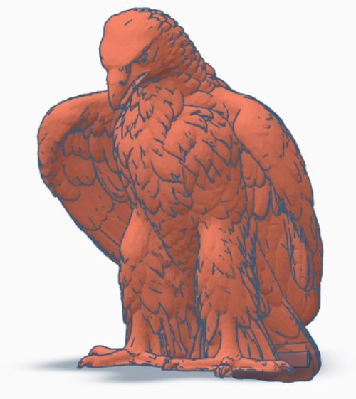
Paul, thanks for the tip! I imported the free eagle to 3d builder, unable to figure out "simplify" in ten minutes playing with the tool and viewing youtube. Will keep trying. Here's an image from 3d builder ..... this eagle, with dais deleted, would be fantastic atop the stern flagpole although I'm not sure how much the detail would hold up at my small printed size.....I saw some eagles with wings spread, now that I know about this tool I will see about getting one of them "simplified" and into TinkerCAD where hopefully I can cut it up for use at the bow. 🤞 Or ask my brother to do it. 😉
- 536 replies
-
- 3
-
-
- Quadrireme
- radio
- (and 1 more)
-
Sorry Pat, the crew figures will be "still lives" on-deck in various positions. The "oarsmen" are completely out of sight, and danger from projectiles, in the enclosed hull which is one of the reasons I decided to build this ship as opposed to, say, a viking ship. Articulated oarsmen are beyond my pay grade. 😉
- 536 replies
-
- 2
-
-
- Quadrireme
- radio
- (and 1 more)
-
Yeah, I think it would look good. There will be a small eagle atop the flagpole at the stern too. I was looking in Thingiverse for a suitable eagle. Downloaded a free one, but the .STL file was too big for TinkerCAD to open (limited to 25M file size). Will be looking again. Also made a start at 3D CAD drawing for the scorpion artillery, before I realized I don't know how they got tilt and traverse with the bulwark in the way, without the machine getting rather too high up. Will have to think more about it.
- 536 replies
-
- 2
-
-
- Quadrireme
- radio
- (and 1 more)
-
Oopsie! My bad - the printer was Halot1 Pro for $169CDN, it is the washer which was $120. Andrew is an animator who worked on Star Wars, Pearl Harbour, The Hulk, and numerous other movies. Looking forward to his help with a crew!
- 536 replies
-
- 2
-
-
- Quadrireme
- radio
- (and 1 more)
-
Thanks Kevin. My goal is to sail (row?) her in the local RC boat club's February evening at a local pool. 🙃 Possibly of interest to you, my brother just bought a Creality resin printer, and washing machine, in a "Black Friday" sale (you may never have heard of it; it was an annual fall thing in the States which has spread to here). Just $120CDN for the printer! He says he has my crew in mind for it. 😊
- 536 replies
-
- 4
-
-
- Quadrireme
- radio
- (and 1 more)
-
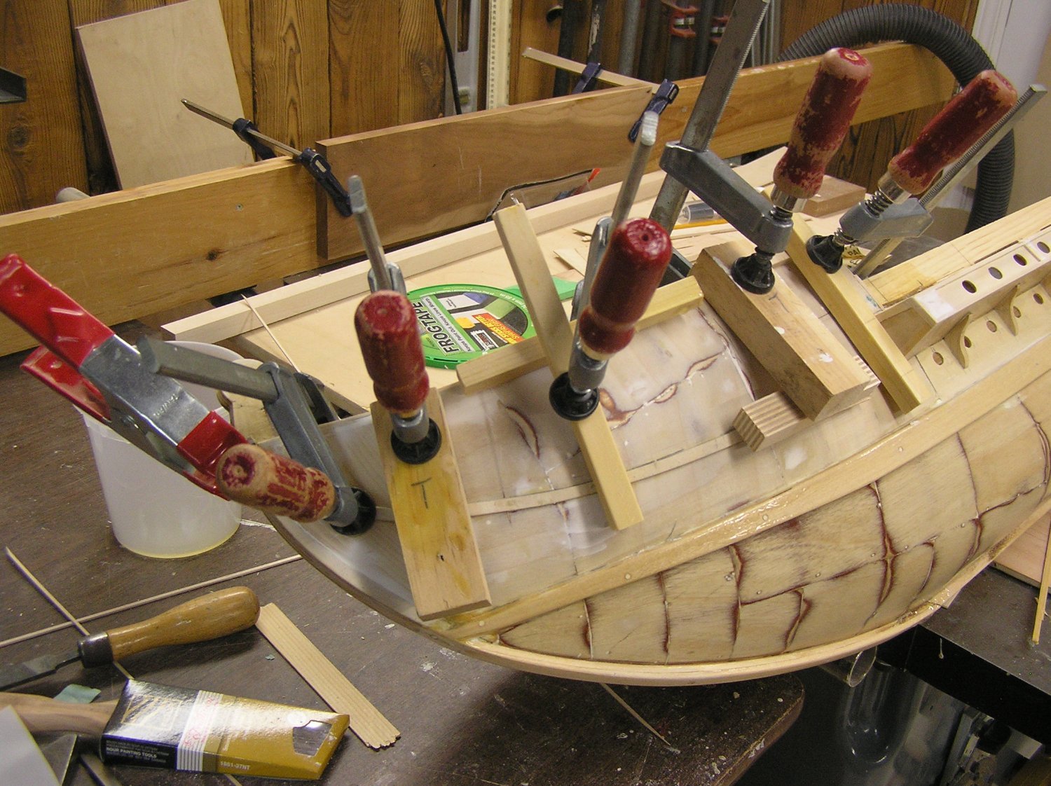
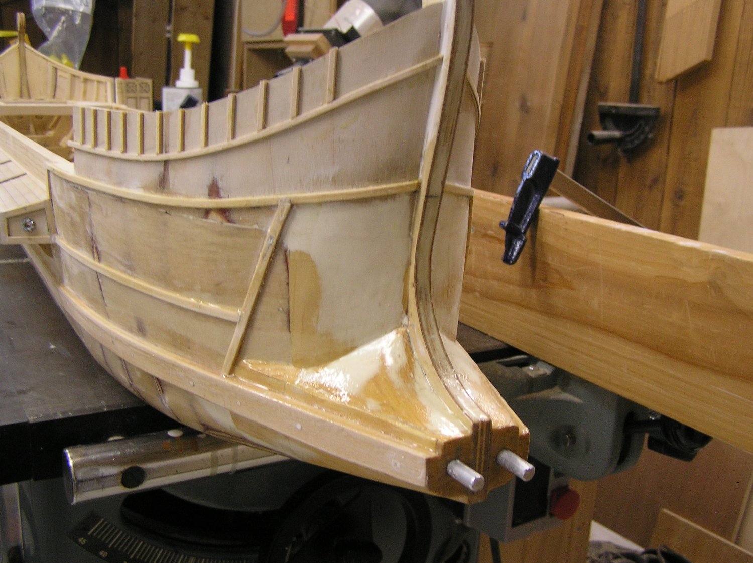
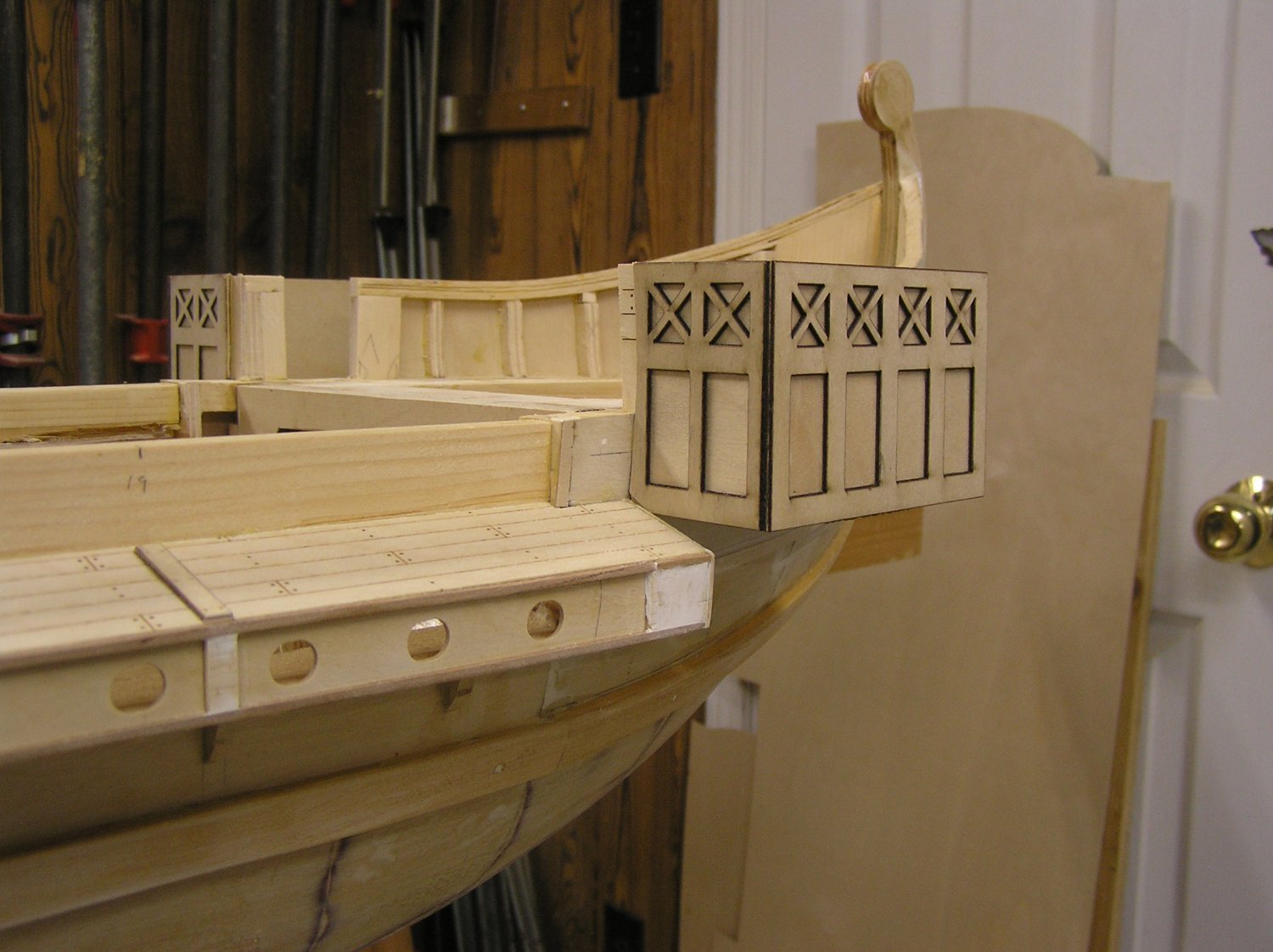
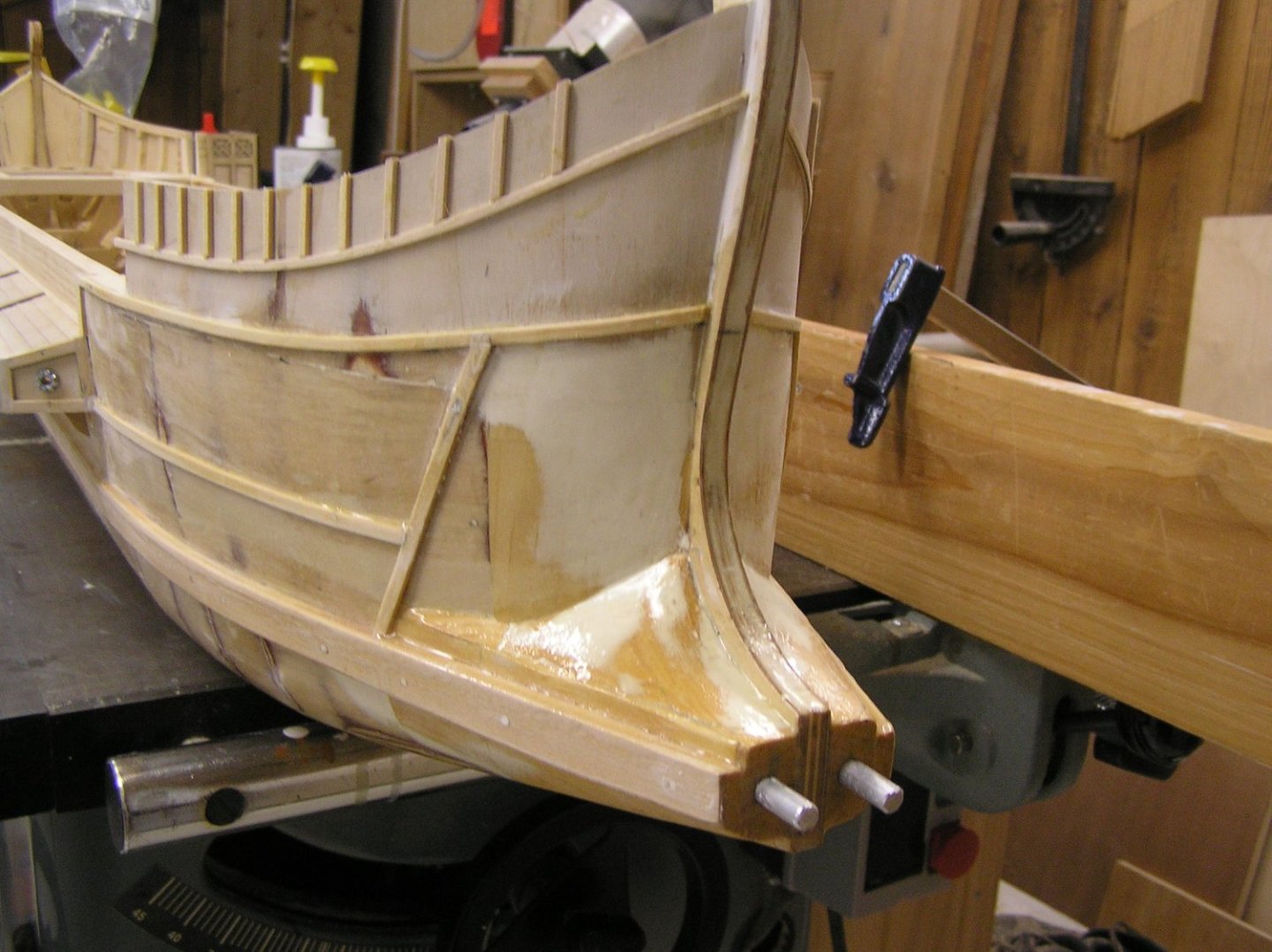
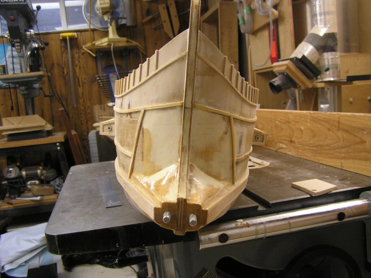
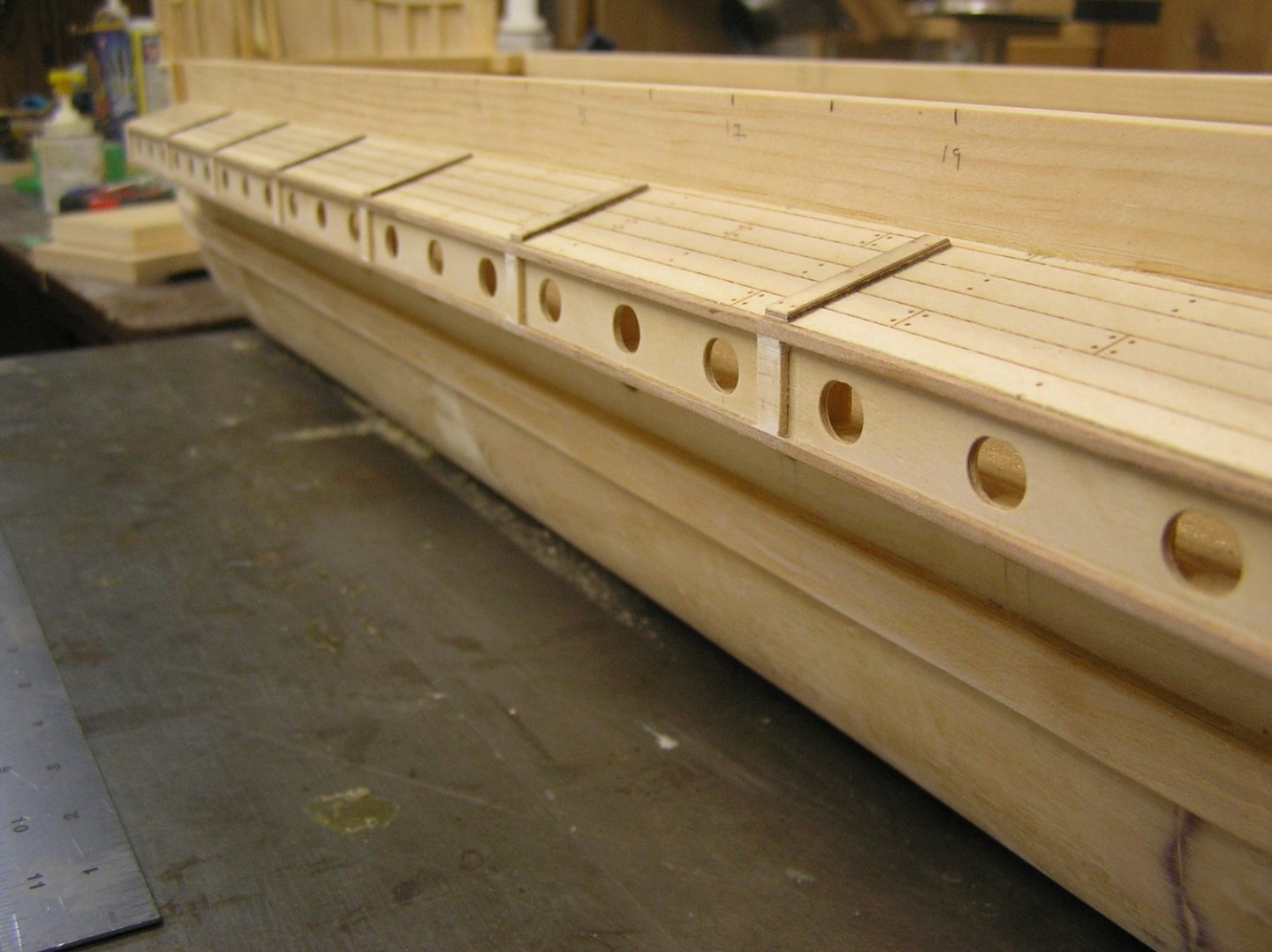
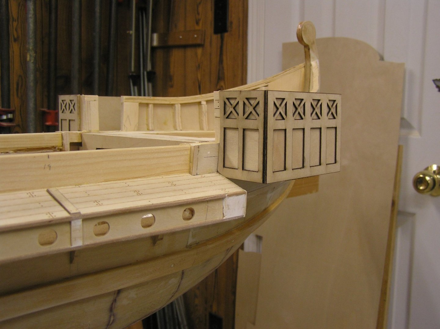
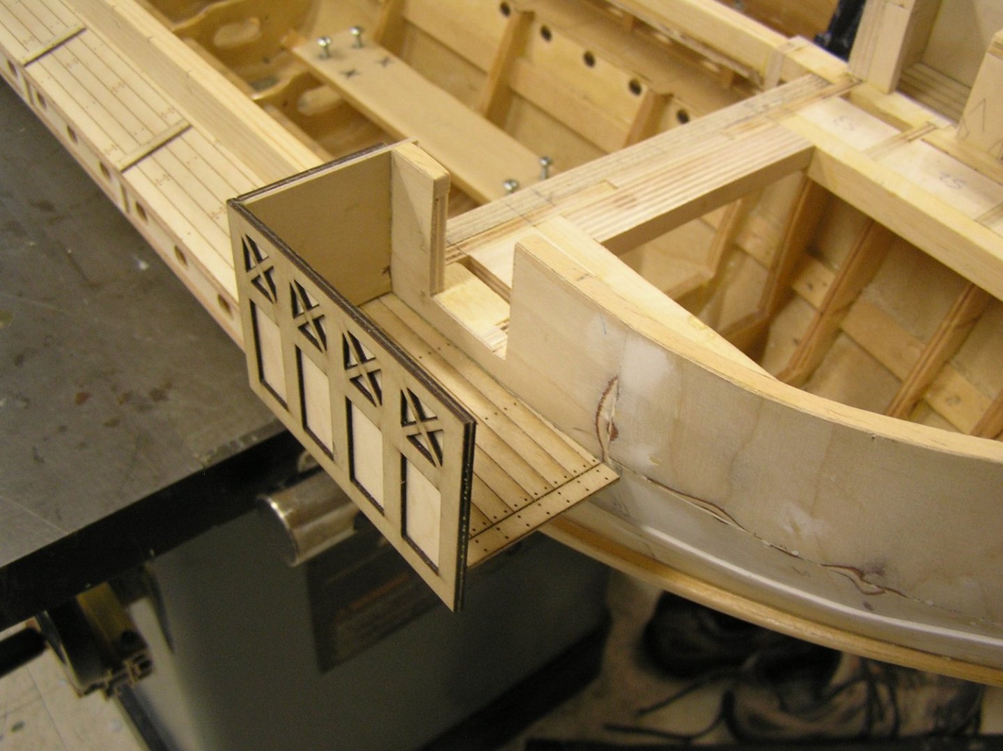
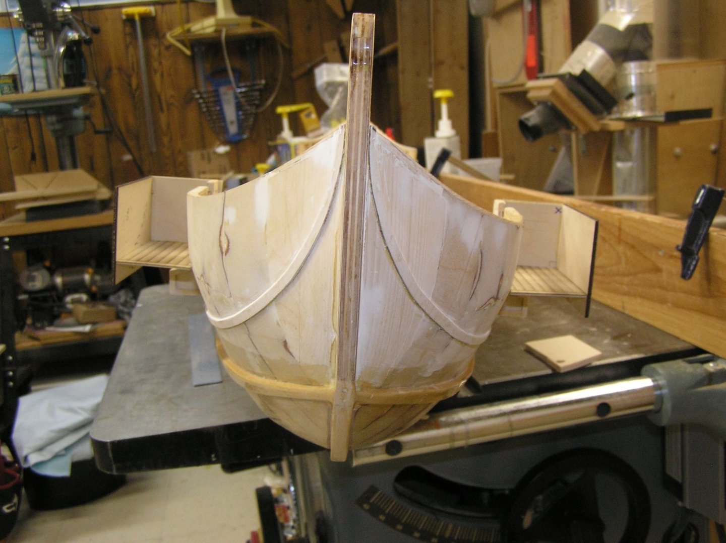
I finally attached the steering platforms after adding most of the exterior trim. Now it's back to the library to laser etch some ply for the fore and stern decks; after adding them I can skin the inside of the fore and stern bulwarks and add the cap rails. I will probably need to add the rudder servo and links before the stern deck decreases access. Pics: Clamping a piece of stern trim. I cheated by cutting the arc from a sheet instead of edge-bending. The bow. The little panels below the (absent) cap rail will be blue with red framing. I left out a couple of forward panels for now; thinking of somehow making or finding a decorative element for there. I drew a little signum in 3dCAD but not sure if it would print, or even if it's appropriate for a ship as opposed to an infantry formation. Maybe a cut-up 3D printed eagle on stempost, with wings extending back into these spaces???? Still pondering. The painted eyes will be in the space at stempost below the trim. Outrigger trim. The little verticals defining sets of three ports were planned originally. The laser etcher could not do the outrigger tops in one long piece; I needed to add a plank to cover the seam so I placed the seam at one of the verticals and added more planks across the outrigger top to match the others. "Make a bug into a feature". Despite what I said earlier I safely cut the trim from wood on my Unisaw by making an auxiliary zero-clearance plate and fence. Port steering platform. They could stand to be 1/4" narrower aesthetically but I figure I need the width to place the rudder shaft outboard enough for the exaggerated oversized rudder to clear the hull, and for the rudder horn to swing. The stern inboard half of the platform will have a shaped block reaching the cap rail level, containing a brass tube for the rudder shaft. This gives me about 2" of "sleeve bearing" for about 6-1/2" of rudder and shaft below the platform. Hoping it won't bind. The horn will be beneath the steering platform deck, concealed from the side by the steering platform's walls which extend below the deck. The stern. There will be one more trim piece, starting at the steering platform at "half bulwark" height and again sweeping up to the cap rail at the sternpost. I must say this part has been fun compared to endlessly tinkering with the oar mechanisms. Still don't know what kind of paint to use. Can't see myself masking and remasking to spray all those little panels, and wales etc. One hobby shop said use whatever paint I like so long as I apply a compatible UV clear-coat on top ......

- 536 replies
-
- 9
-
-
- Quadrireme
- radio
- (and 1 more)
-
Nice job so far. Your workbench looks like mine .... 😉
-
I recall standing at the foot of Cutty Sark's foremast looking up along the mainstay. It was a curve, tight I grant you.
- 1,508 replies
-
- 1
-
-
- Le Soleil Royal
- Heller
- (and 1 more)
-
Oh Bill, just leave well enough alone! Your stays look great, job well done! On to the next task......👍
-
Not an expert, but any given rope or wire stay with say nothing attached along its length will sag in a catenary curve. No real stay on a real ship is a straight line. These old-time ships with braces attached far from the ends of the stay would have to result in distortion of the stay; having the stay remain undisturbed would require the stay's tension force to hugely exceed the sideways pull exerted by the brace if the sail is drawing. I'm trying to think of an analogy but I'm drawing a blank right now .....
- 1,508 replies
-
- 1
-
-
- Le Soleil Royal
- Heller
- (and 1 more)
-
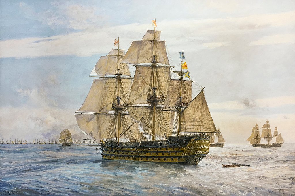
I don't see where you proposed that sail plan above, but yes it would be fine. Or you could do something interesting with the courses as in my print of Victory sailing into Trafalgar, below. Notice how the windward clew of the mainsail has been pulled up a bit to allow the foresail to catch some more wind as Henry alluded to above. Note the breeze was very light on the morning of Trafalgar so all sail was set, even stunsails, to reduce the time spent enduring enemy fire without being able to reply. In fact, sources say they approached the combined Fleet at a casual walking pace all the while under fire.
- 1,508 replies
-
- 1
-
-
- Le Soleil Royal
- Heller
- (and 1 more)
-
That is not nautically inaccurate. They weren't slaves to particular sail combinations in light airs. The diagram I posted depicts the steps in reduction from full sail, under a situation of continually increasing wind strength. As Veszett says, in battle the courses were usually furled to reduce fire risk.
- 1,508 replies
-
- 1
-
-
- Le Soleil Royal
- Heller
- (and 1 more)
-
Bill, just looked back at your photo. With your fore topgallant and topsail yards fully raised as they are, the sails need to be fully set to be correctly rigged. If you want to furl either, or reef the topsail, you will need to lower the appropriate yard(s) as I explained in post above.
- 1,508 replies
-
- 1
-
-
- Le Soleil Royal
- Heller
- (and 1 more)
-
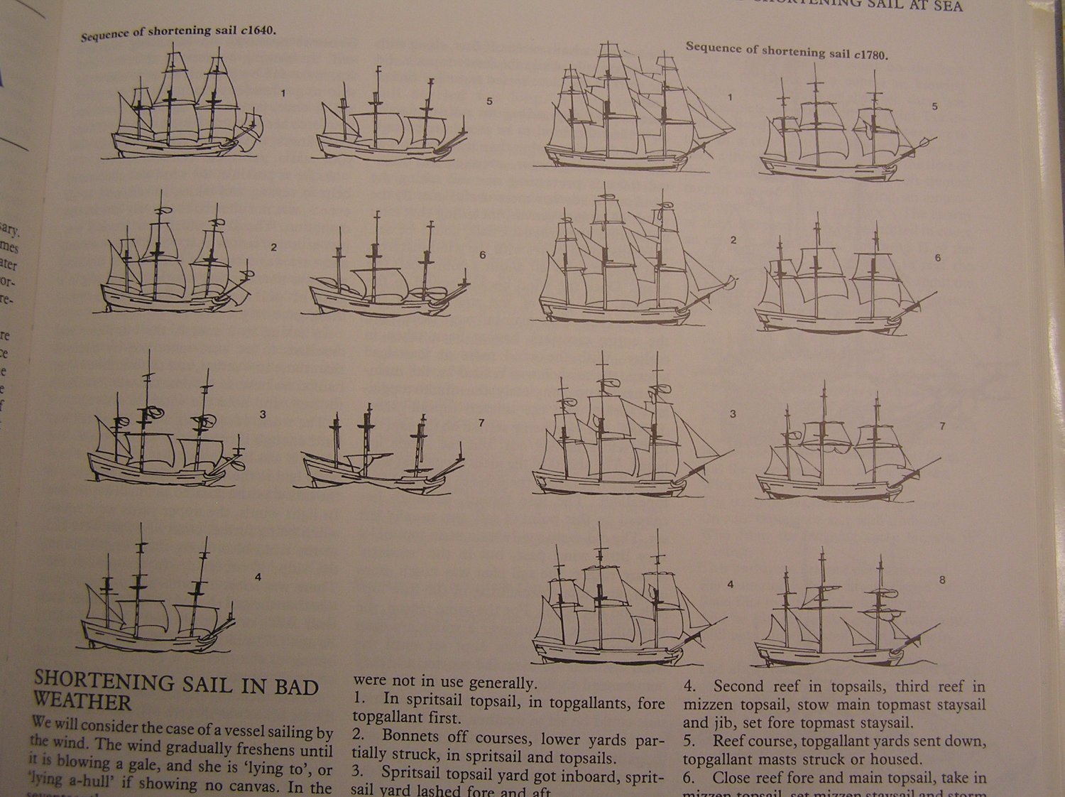
Bill, to put this topic to rest, here is a diagram from Harland's "Seamanship in the Age of Sail", showing the order of taking in sail and thus which combinations are realistic to depict on a model. Note on the c1640 example no reefs are present, a sail is either set or furled (or partially furled on one side see diag #7 with all topmasts struck and just a corner of the course showing). For c1780 reefs are common and one can see the topsails, then the courses, gradually reducing in area as the wind increases. Note how the topsail yard lowers by degrees as more reefs are taken in so if you want to show a reefed topsail you should have the yard lowered on the model. Heller shows SR with reefs, I think we discussed this before, I think Mark stated it could have had them assuming we are modelling SR2.

- 1,508 replies
-
- 2
-
-
- Le Soleil Royal
- Heller
- (and 1 more)
-
Hi Bill; I think it would be unusual to be sailing a square rigger on topgallants only. If there's a strong breeze, the topgallants would be the first sails furled since (a) they exert a lot of leaning force, being high up, and (b) the spars are smaller and weaker up there. If there's a light enough breeze to use topgallants, then other sails would be unfurled before them. Typical situations for you might be topgallants furled, one reef in the topsails, courses furled; or maybe courses set, two reefs in the topsails, topgallants furled. As for the staysails, if you have them set then the square yards should be turned far to one side for sailing close to the wind.
- 1,508 replies
-
- 2
-
-
- Le Soleil Royal
- Heller
- (and 1 more)