Ian_Grant
-
Posts
2,156 -
Joined
-
Last visited
Content Type
Profiles
Forums
Gallery
Events
Everything posted by Ian_Grant
-
 Michael, as always, fantastic model! I can't get over how your crowfeet don't distort the run of the stays. Beautiful. By the way, what are you using for ratline thread?
 -
Held my nose and ordered another aluminum channel beam from ServoCity, paying the usurious shipping rates to Canada and the inevitable "brokerage fees", shipping taxes, brokerage taxes, and Canadian taxes on the sum total ie taxes on taxes. I have some tea in the pantry; where's the nearest harbour? Making slow progress on the 2nd mechanism. I want to make a second water test with all lower oars this week because we are leaving on the weekend for two weeks in the Yukon and NWT. Here's a pic of current state.........

- 536 replies
-
- 9
-

-
- Quadrireme
- radio
- (and 1 more)
-
Really like your stand, Bill. And the ship, of course!
- 1,508 replies
-
- 1
-
-
- Le Soleil Royal
- Heller
- (and 1 more)
-
Over here, waterproofed matchsticks for camping are generally green. Glen, what can I say? I'm running out of superlatives for this build. Your scorpios are Aaah-maaaaziiiing!!!!
- 290 replies
-
- 4
-

-
-
- Quinquereme
- Finished
- (and 1 more)
-
Looks great Glen! Must have been very fiddly. Just a note that they weren't actually made of stone, just sometimes painted to resemble it. They had to be very light weight wood and canvas affairs to not affect stability. In fact they were later made to be collapsible and stored flat on deck during heavier weather.
- 290 replies
-
- 3
-
-
- Quinquereme
- Finished
- (and 1 more)
-
Agree with George....and I love the brass etch trailboard decorations ..... day and night compared to the decals.....keep up the good work .... I admire your commitment.....
- 89 replies
-
- 2
-
-
-
- Cutty Sark
- Revell
- (and 2 more)
-
Yes, the corvus was a Roman invention for the first Punic war. They soon discovered that the additional weight, and possibly the removal of forward bulwarks to allow deploying it at various angles, made the ships even less seaworthy so it was obsoleted. The new solution was a lighter-weight "boarding bridge" which could be manhandled over the side, and was stored lying athwartships on the forward deck, between new bulwark openings used to deploy it. You can see it sitting on the deck around the 21 sec and 53 sec marks in the following video (I meant to send you this video earlier, not the short fast one but couldn't find this at the time). That's a really beautiful model; I'd love to buy one but they are out of production, very difficult to find, and presumably $$$$. There's another video before this one showing his stages of the build. I'd love to know where he found his crew too! By the way, looking forward to seeing how you represent scorpio artillery at your miniscule scale. I'm wondering how to make them for mine!
- 290 replies
-
- 4
-
-
- Quinquereme
- Finished
- (and 1 more)
-
Glen, this is amazing ..... I love the bulwark decorations!!! For some more ideas on finishing this ship, check out the following video: https://m.facebook.com/Cast-Your-Anchor-Hobby-246287451905/videos/roman-navy-galley-warship-model-boat-awesome-cast-your-anchor-specializes-in-sta/325854628861004/
- 290 replies
-
- 4
-
-
-
- Quinquereme
- Finished
- (and 1 more)
-
Sorry to hear that ...... the usual sequence would be stays first since they're along the centreline and soon become less accessible, then backstays. When rigging each stay, I attach a temporary backstay to the next mast behind, or something convenient, so I can tighten the stay and the backstay to ensure the mast is straight when I fix the stay. For this stage I work from stern forwards.
- 89 replies
-
- 2
-
-
-
- Cutty Sark
- Revell
- (and 2 more)
-
Bill, if that is "S2" coloured in green in your pic, yes it is the mainstay, hooked at the shoulder in the stem below the bowsprit. You'd need to slide it down the bowsprit before adding the gammoning (will it go past your sprit-topmast?) if you want to tie the loop off-ship. It might be too late for you. 😒
- 1,508 replies
-
- 1
-
-
- Le Soleil Royal
- Heller
- (and 1 more)
-
As long as I don't go past the point at which the grip on water requires too high a continuous torque from the sweep servo....🤔
- 536 replies
-
- 3
-
-
- Quadrireme
- radio
- (and 1 more)
-
I think mine is perhaps more overweight than underpowered; I had to put in several pounds of lead to load to waterline. On the other hand it still lacks the second mechanism and the entire deck etc. When I guesstimated the ultimate weight of the wood hull I was conservatively heavy - better to turn out lighter and need ballast than heavier and sit too deep. You may recall I weighed my old battle-cruiser empty to see what its wood etc weighed; I'm wondering now if maybe I placed some ballast in the inaccessible areas in her bow and stern as I built her, 40 years ago....... I'm thinking of replacing the oar blades with blades 1/2" longer to catch more water, since the loom length was increased by 1/2" when I changed the geometry of the outrigger. It would be a bit painful but perhaps helpful.
- 536 replies
-
- 3
-
-
- Quadrireme
- radio
- (and 1 more)
-
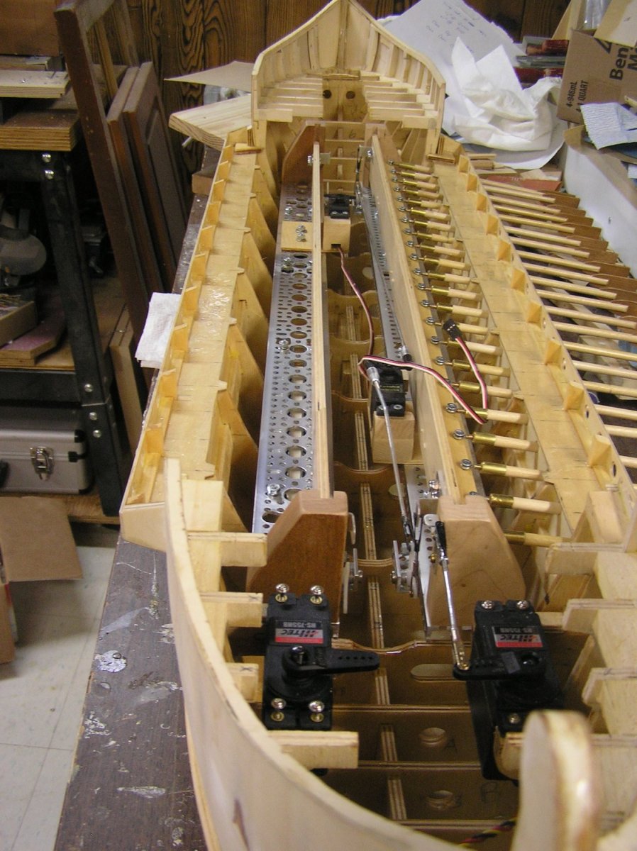
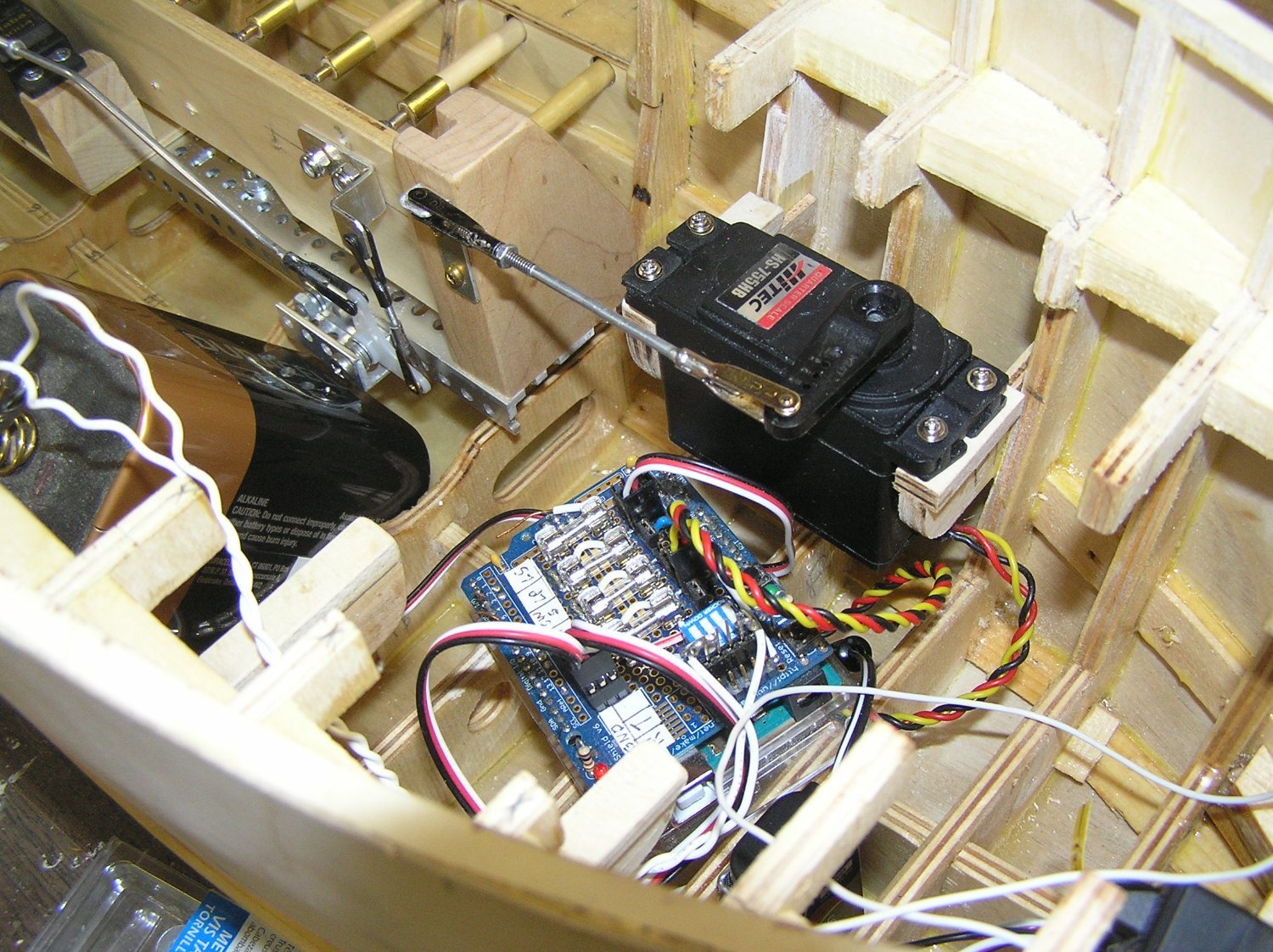
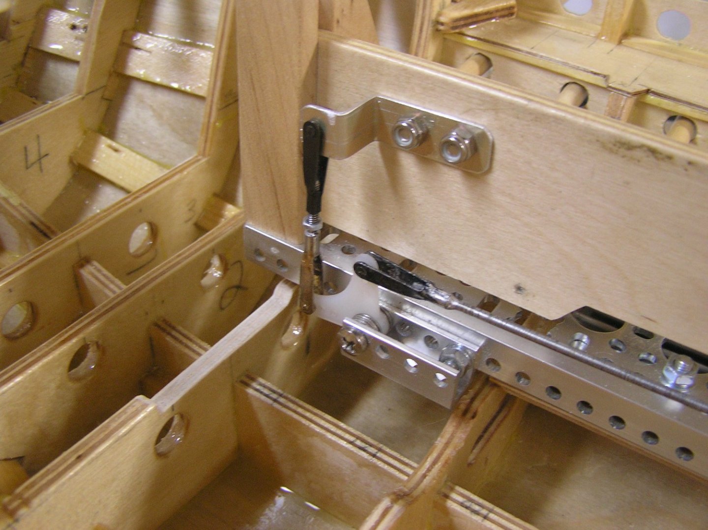
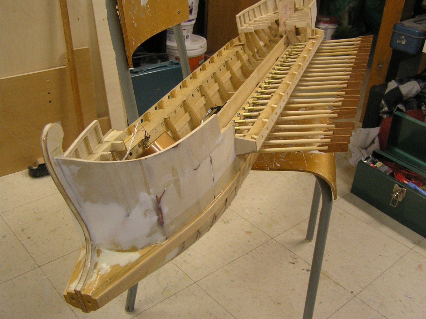
An abortive first water test has been conducted!!!!!! The port side mechanism is installed but only with the lower oars; upper oars need to be longer but I haven't made any yet. Here are a few pics. "Giant" scale sweep servo in port bow and linkage to mechanism. The standard size lift servo is just seen at left, along with the lift linkage at this end of the beam. Arduino electronics at centre. Still powering from a lantern battery for now. Lift linkage at the aft end of the beam. Shot from the bow. It was a nice, though sweltering, evening at suppertime. While I was putting lead shot into ziploc bags a storm started to blow in. By the time I got the ballast right there was a gusty wind blowing. Between that and the pool's circulating current it was hard for the galley to react to its oars, but I can see it will be pretty weak. I conclude that Richard Braithwaite was correct when he commented these models are for calm days only. Does it work well enough to bother continuing? Test is inconclusive for now, bearing in mind that it only has half the oars on one side. Might have to drive oars unrealistically quickly to get tolerable boat speed. Still, it was good to see it function without its umbilical USB connection to the laptop. Will try again tomorrow if it's calmer. ps My daughter watched and recommended adding a "cheat" propeller. 😭

- 536 replies
-
- 8
-

-
-
- Quadrireme
- radio
- (and 1 more)
-
What indeed? Storing and transporting will be a chore. It will be 54" long and 22" wide with the oars thus very difficult to pick up in and out of water. I drilled holes in two bulkheads straddling the amidships point; plan is to add two metal supports, bolted in, with holes to attach some sort of handle when needed. Or maybe even have a permament handle rising to just below deck level. In the longer term I'll probably get bored with it once the novelty wears off and try to sell it. Assuming it works at all. As for our cat, he "settles" on our laps every time we sit down. 😉 My vet wife says orange tabbies are usually quite cuddly.
- 536 replies
-
- 4
-
-
-
- Quadrireme
- radio
- (and 1 more)
-
Beautiful job! Sadly, I couldn't find a commission pennant for mine at the time; might add one someday.
- 527 replies
-
- 1
-
-
- caldercraft
- victory
- (and 1 more)
-
HaHa! 😃 I read quite a bit of Polybius at the cottage on the weekend. Haven't yet reached the attack on Syracuse in the 2nd Punic war, but there was an interesting story about a battle between two of the restive Greek states between the Punic wars, not involving Rome. One side lashed their ships together in fours and put many marines on board. They then allowed them to go broadside on to tempt the enemy fleet. When the enemy ships rammed the outer ships of the lashed sets and became stuck in them, they were overwhelmed by marines boarding while the inner ships of the lashed sets held all afloat. Many quinquiremes were captured. Polybius has a good opinion of himself. He considered himself a "serious" historian and did research (and was actually present at some engagements) but he decries some other historians who recorded, in today's parlance, misinformation. Reporting on previous "historians'" discussions of a Roman senate meeting, he says, "All of this is as implausible as it is untrue - unless, of course, one of the gifts with which Fortune has blessed the Romans is that every one of them is born wise. But I need say no more about the work of writers such as Chaereas and Sosylus. Their work seems to me to have the status and importance of the common gossip of the barber's shop. It is not history." ...... LOL
- 290 replies
-
- 5
-

-
- Quinquereme
- Finished
- (and 1 more)
-
To carry on a little more with this distraction: My wife really wanted to see the marine iguanas; she is a vet who looks after exotic animals (birds, reptiles, and plain old cats and dogs too) and this species is unique. I on the other hand really wanted to see blue-footed boobies, which we did, literally walking right by them. In fact, you are only allowed to walk on a designated path but some of the boobies, which nest on the ground, were sitting on their eggs in the middle of the path and you had to tip-toe around them as they stared at you. I can now say, to quote Dr. Maturin, "I have beheld the blue-footed boobie!". Mike, did you leave a postcard at Post Office Bay? Background for the uninitiated: in the 19th century whalers had a mail barrel on the beach here hence the name. Newly arrived whalers from Nantucket would bring mail for all the crews already in the Pacific and drop it in the barrel. When a whaler watered in the islands, they dropped mail for home into the barrel and picked up any incoming mail for them. When a whaler was leaving for home, they picked up all the mail for home and took it with them. Nowadays you buy a postcard, address it to yourself, and leave it unstamped in the barrel. While there you search through all the postcards to see if you can find one addressed to somewhere very close to your house. If so, you are to take it home and go to the peoples' house, knock on their door, and hand it over "special delivery". I was amazed to find a card from people a few streets over. We've been over a couple of times but they weren't home. Unfortunately, we recently received OUR postcard in the mail; someone brought it back to somewhere in Canada, stamped it, and mailed it to us. 😒 Idiots. It would have been a great surprise and pleasure to have someone come to our door with it instead, someday.
- 290 replies
-
- 6
-
-
-
- Quinquereme
- Finished
- (and 1 more)
-
Glen, the hull looks great, and amazing job drilling so many tiny holes consistently! I wondered how you were getting the angles right; bending the brass oars is another great idea. I'm certain this will end up being my favourite among your builds so far. 👍
- 290 replies
-
- 6
-
-
-
- Quinquereme
- Finished
- (and 1 more)
-
As I read it, after 1650 (and probably before) the deadeyes were stropped in iron, "probably" (he says) with iron "puttocks"/"futtocks" hooked into them (much the usual way for topmast futtocks) and the bottom ends of the puttocks bolted near the bottom of the bowsprit. The first way with deadeyes stropped in rope and puttocks above the bowsprit seems to me like a mechanically inept way of doing it, with all the sprit topmast strain taken by the knee of the top instead of the bowsprit; probably why Mr. Andersen is unsure of the scheme.
-
Thanks! The blades are from cherry cutoff I had around; looking forward to them getting redder and darker over time. Thanks Marc! All due to jigs...😉
- 536 replies
-
- 4
-
-
- Quadrireme
- radio
- (and 1 more)
-
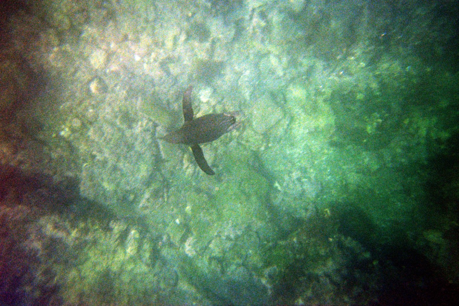
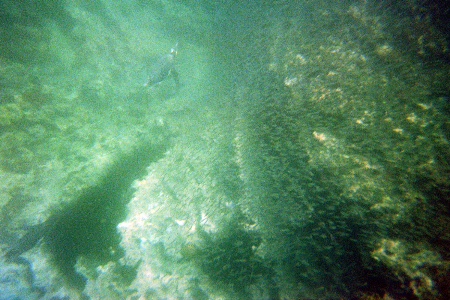
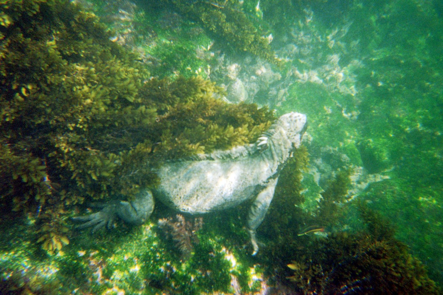
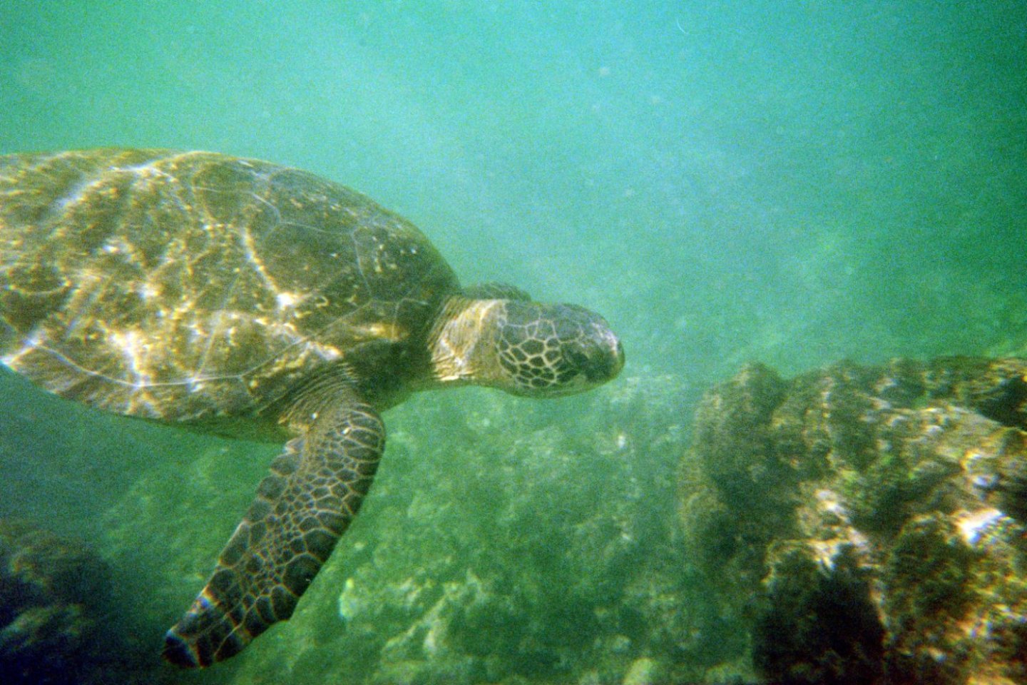
Speaking of penguins ... 🫢... here are a couple of crappy pictures I took of a Galapagos penguin during one of our snorkels on our recent trip. My camera was one of those cheap "rentals" made of a roll of Fuji film encased in a plastic enclosure. I'm quite proud I managed to capture this little torpedo while peering through the tiny viewfinder with a snorkel mask on. Not too impressed with the film though; back in the day I used ASA400 for u/w shots. Not sure what this was. Should have bought a go-pro for this once-in-a-lifetime trip. I did get some better pics, a couple of which I added below. A couple of marine iguanas (the only iguanas in the world that swim and eat underwater), and a nice one of a sea turtle which shows improved quality when camera is pointing more horizontal as opposed to towards the bottom. By the way these iguanas get rid of excess salt intake by sneezing it out when lying in the sun on black volcanic rock on land to warm up again. On one of our walks we passed by hundreds/thousands of them with someone sneezing out white salt particles every few seconds. Oh, and my wife shot about 1800 pics on land with her digital SLR. Trip of a lifetime!!!! If you are at all interested in wildlife, I highly recommend the Galapagos. Glen, sorry to hijack your log! Carry on.....


- 290 replies
-
- 7
-
-
-
- Quinquereme
- Finished
- (and 1 more)