


Modeler12
-
Posts
1,716 -
Joined
-
Last visited
Content Type
Profiles
Forums
Gallery
Events
Posts posted by Modeler12
-
-
I actually use my mill a lot. For fine drilling I use the Sensitive Drilling Attachment, and for regular drilling I use the z-axis hand wheel. I stopped using my mini drill press, so I sold it.
I recently used my Rotary Table and the Tilting Angle table to produce the mast tops for my Paragon (modified Mayflower).
I still consider myself a novice, since there is so much more to learn.
Great work, Frank. And I find it interesting that you use the mill a lot.
I just ordered the tilting table and rotary chuck from Sherline and am looking forward to doing some experimenting.
I am sure it will take some time to do what you showed above.
But it is all in the name of 'having fun with new toys'.
Would you explain what a Sensitive Drilling Attachment is and how it works?
- Landlocked123 and Canute
-
 2
2
-
Sorry Chuck, but I still think that a much simpler way is to measure the thickness of the thread or rope in question at several places along its length. I use a dial indicating pair of calipers that read to within .001 inch and have generally found very little variations within samples of thread and rope (if made correctly and of uniform shape).
I compared that against the winding method you mentioned and found no significant differences.
If there were to be a variation of a mil or two, would that matter????
My little rope rack is marked with the 'nominal' and I don't worry about the details.
-
Model rail spikes?
they are blackened iron, come in 3 sizes, and have the peened head. At least one person has posted pics of their use here on MSW.
The problem with rail spikes is that the tops are not symmetrical, they have an elongated top.
I would go with what Bill suggested above. Use molded nuts or rivet heads that come in a wide variety of sizes. They also can be bought from model train suppliers.
Try these: https://www.tichytraingroup.com/Shop.aspx?SearchValue=rivets
-
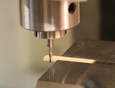
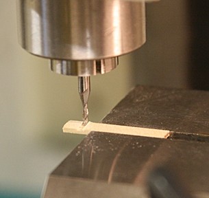
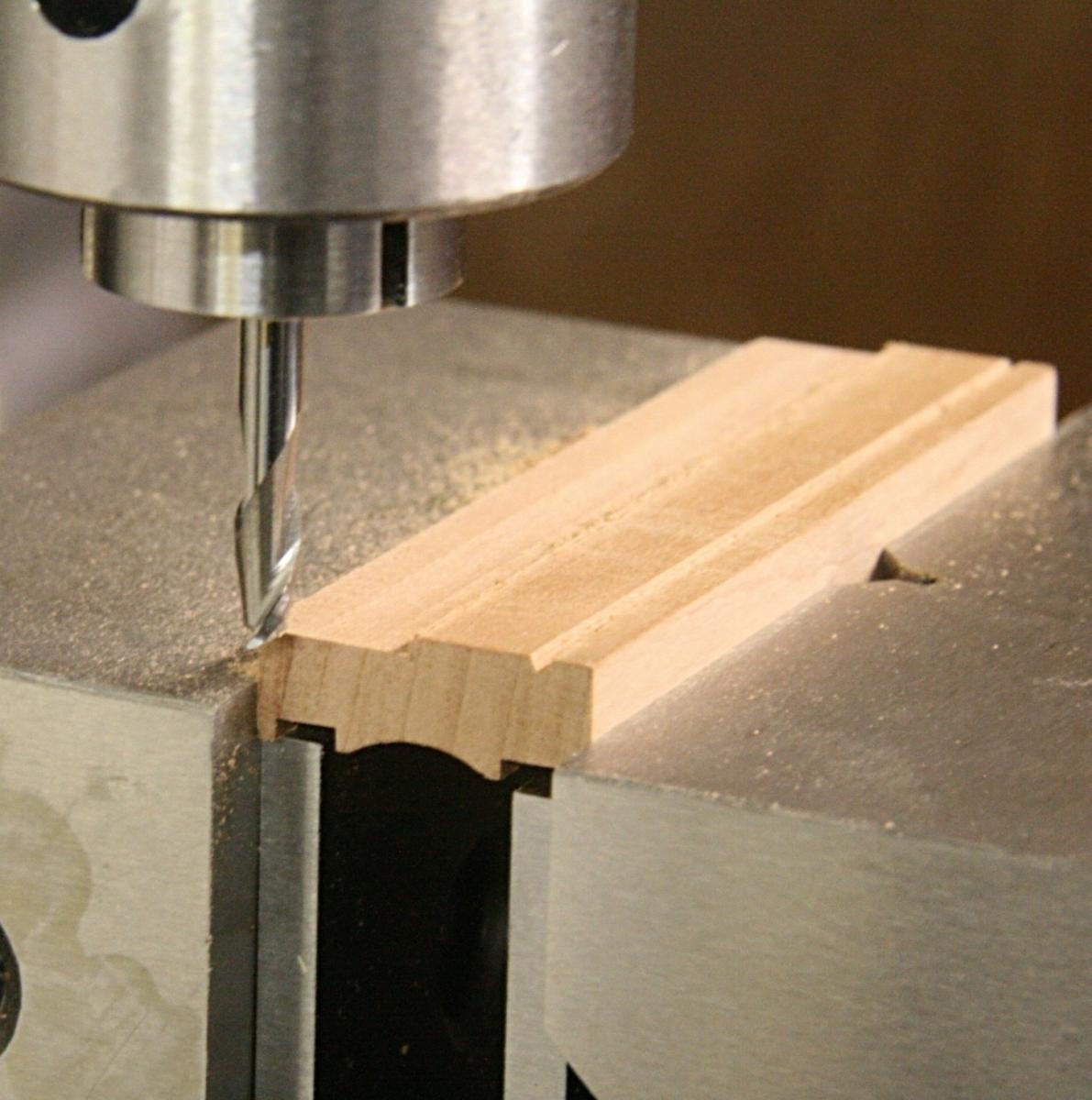
In the first picture above someone might say 'I can cut that slot with a saw'. But can you do this with a saw?
This is a 0.020 inch wide groove/slot/carving, you name it.
I went back and forth as well as at an angle and the bit at that same depth held steady at 5000 rpm.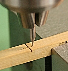
-
Here are a couple more ideas about using the mill.
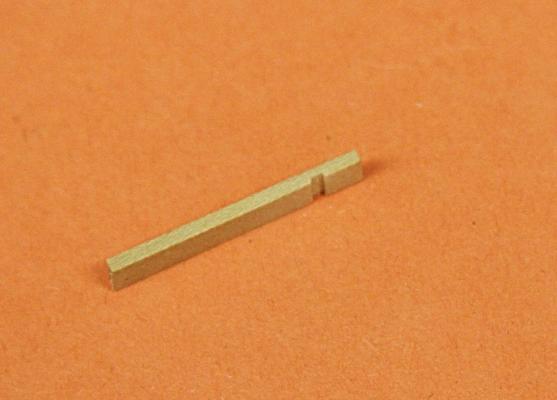
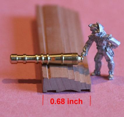
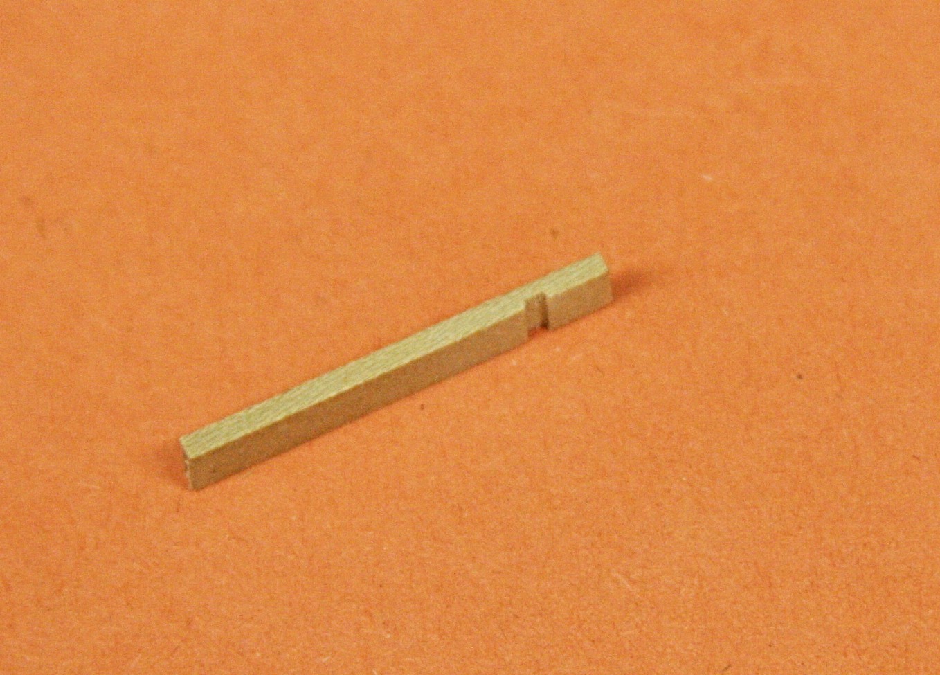
I mentioned my broken drill bit. It is 0.5 mm diameter and has a nice thick shaft. I cut a groove (three passes, so it would not break it again) and here is the result.
Not bad for a failure.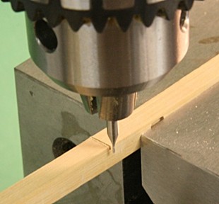
I have done a fair amount of wood working and have collected router bits.
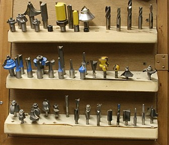
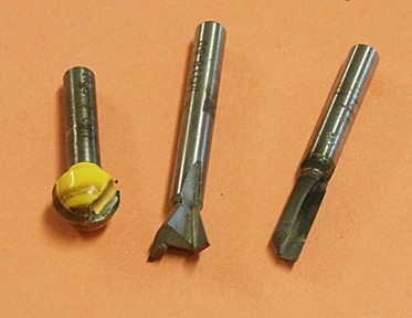
They work just fine in a mill and I have used the round one, for example, to make the gun carriages I mentioned above.
A couple of these I inherited from my father-in-law who had a die-casting shop and made his own dies.
So, now I have straight bits that go from 1/2 inch diameter down to .020 inches.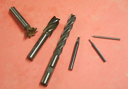
And we haven't even talked about making your own spacial shapes!!!
- CaptainSteve, mtaylor, hornet and 5 others
-
8
-
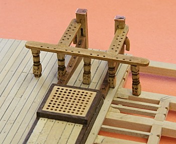
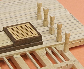
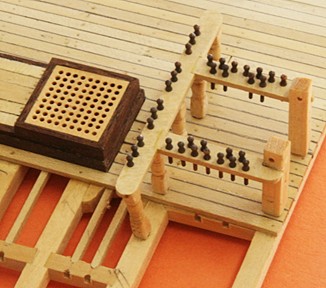
The forward fife rail is done. After I install it during the final assembly, the posts and riding bits will be glued in place and the whole will get a brushing and a couple coats of Polywipe. For now they go into a box along with other 'furnishings'.
Onto the next step which is????
-
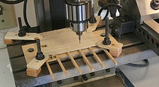
Actually I use my mill a lot to drill holes. I show two pictures above that have the grating and the fife rail parts.
I would not have been able to do this in a regular drill press because of the accuracy I wanted in indexing the hole locations.
Being able to move the table in and out is very useful when you need a hole located in the center of a narrow piece of wood, for example.
One thing I would like to add is a digital read-out system. Counting those turns of the crank can become a pain after a while.
Some time back there was a thread about the evaluation of my mill
I should add that to ship one of those heavy machines to Austalia is not cheap. There you might consider a smaller version such as offered by Proxston.
-
Frank, when I got mine, I made it a point to learn as much as I could about how to use it. That is easy to say and a bit hard to explain.
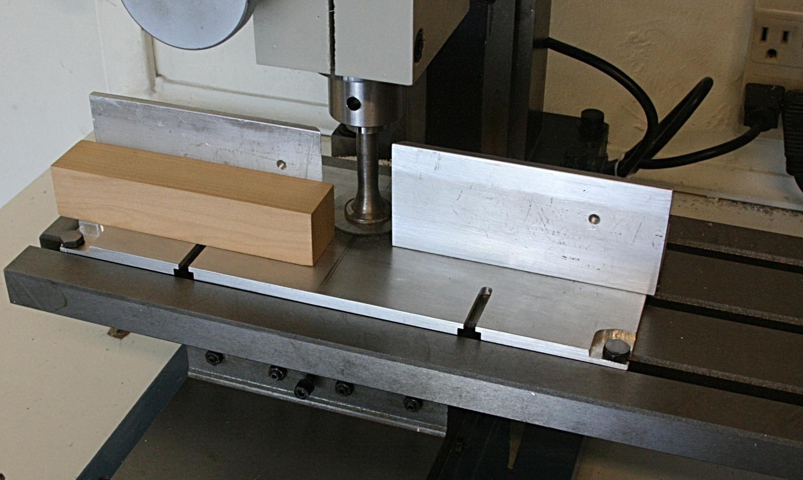
The upshot is that a mill is not like your computer. If you do something wrong with a mill it may cause more than 'headaches' . So be sure to know what you are trying to do before turning on the dials. Yet, once you are sure, don't be afraid and follow your plan. Go for it.Here is an example how I mount a tiny piece in the vise. It is outboard, but firmly in place. I can carefully machine a groove, whereas if I mount it in the center of the vise, I have no room to clamp (or run the bit into the vise).
The groove is .060 inch wide and .020 inch deep.
First I establish where X, Y and Z are. Then I move the table to the front of Y and index the Z.
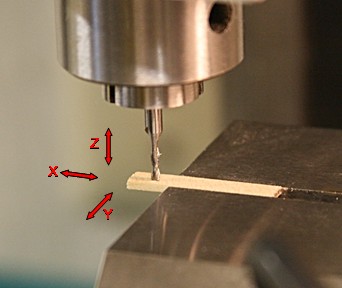
Route and see the final piece below.
Oh, I forgot to mention, I used a bit that was 0.060 inch in diameter.
-
Mark, I will have to try your idea about the broken drill bit. When I used my broken bit, it did a so, so job. But to add a bit of gump at the end would work better.
Goes to show you to not throw anything in the scrap bin until you are sure you can retrieve it later.
OK folks, don't ask what gump and swarf mean. You know!!!
-
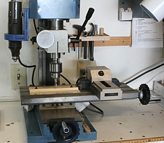
My current setup is as shown next. I have the vise accurately mounted and try to keep it that way. I use it with bits that take the collets. For flat parts, that can be mounted on the plywood panel, I use the Jacob’s chuck. It is quite accurate and takes drill bits down to around #75.
The plywood panels are easy to make and I have a couple for different edge machining.I also made a mounting bracket so I could attach my old rotary tool (a Monkey Wards left over, that works great). Speeds now are from zero up to 10000 rpm (never measured that, I don't care, it works fine).
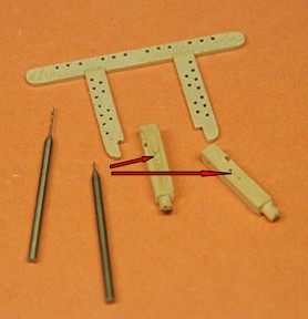
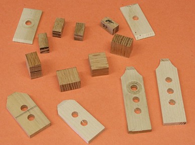
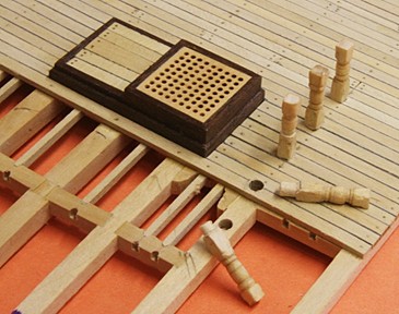
Finally I want to share a little trick. It is the result of a failure to start with. I broke one of my 0.5 mm drills, but saved the broken piece. Later, when making the sheaves in the riding bits shown below, I drilled the holes through with a new bit, but used the broken one to score the grove that connects the holes. This was done by clamping the riding bits in the mill’s vise and slowly feeding the broken bit (at 5000 rpm) across. The picture is not very clear, but it worked.
Are there any other ideas floating out there???
- keelhauled, hornet, ScottRC and 9 others
-
12
-
I realize that not too many modelers have a milling machine, but for those lucky enough to have one, I would venture to say that it is a very versatile and useful tool for scratch builders as well as those who want a bit more accuracy in cutting material.
I am constantly learning to use mine with new ideas for fixtures and techniques. Perhaps we can share some ideas on this thread.A couple years ago there was a thread dealing with this subject and I like to revamp that:
http://modelshipworld.com/index.php/topic/4320-milling-work-and-miniature-jig-making/page-2?hl=+milling%20+machine.Let me show you a few things I have done to and with my machine.
When I first got it, I wanted to learn the basics and made this aluminum slitting fixture. It can be used to make slots or even cut planks. Now I don’t use it too much anymore, because it takes a while to set up and takes away space on the table.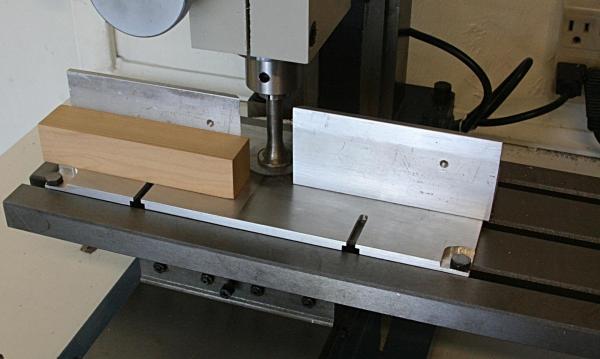
I have a four inch vise that is very accurate. Using the parallels underneath this piece of pear, I was able to machine this log of gun carriages. After the milling I cut slabs that were only 0.050 inch thick.

When I decided to make my own gratings, I had to make a decision about square or round holes. After some experimenting I gave up making square holes. Now I find it hard to tell if the grating has square or round holes (when viewed a few inches or more away). My point here is that I placed the grating material on a piece of plywood that was clamped to the table and used the mill’s x-y table movements to accurately drill the holes.
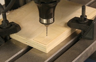
Since then I don’t use the metal clamps that you see in the picture above. I made a number of wooden clamps and blocks that do a better and safer job.
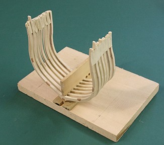
Here is a set up using those clamps. It was part of my cross section work.
More on the next post.
-
Interesting comments, Tim.
I mentioned earlier that my reason for building the cross section was to compliment the full size model that I built from a kit. I am not that involved with the history of the ship and all the modifications that happened over its life span. Hence I took what I thought was a logical approach and followed the drawings in Marquardt's book. Unfortunately he does not clearly state the source and date that those drawings represent. I still think he made a major error in the location of the aft riding bits, oven, chimney and the subsequent deletion of hatches on the gun and berth deck. Even the Wade drawing of 1812 verifies my statement.
As a result, I have now done what you mentioned above, I am doing this model my way using the best information available and not worrying about real or imagined modifications that occurred over the last 200 plus years. Even right now they are doing some 'repair' and 'refurbishing' work that may end up giving the bulwarks a different appearance. So why worry?
-
The posts and rails turned out nice Jay. Your method for making all the belaying pins identical in size seems to have worked out great. What was that method anyway?

It is called 'buy them on the internet'.
I will have to look that up, but I have lots of them in brass and I simply blackened them.
I will need more for the side rails much later on, so there is a box full (well, not full, but you know what I mean)
People do not realize how long and difficult those small bit are to do crisp and clean Bravo and good eye.
David B
Thank you David. But the right equipment helps.
A couple years ago, when I started with my full scale Connie, I though I had most of the tools I needed. After all, I have been dong wood working for almost 50 years. But that was making furniture. decking, crown-moulding, etc.
The small stuff was a experience to me and eventually I invested in a mini lathe and a mini mill to do what I like best now.
It has opened a whole new world of making small models for me.
More about all of this later (and I won't even mention what I have learned about brazing metals, making rope, using my wife's sewing machine, etc).
- dgbot, Canute, CaptainSteve and 3 others
-
6
-
To continue the 'furniture' on the spar deck.
I changes my mind about making all of the fife rail pieces one assembly.
There are seven posts and holes to align and I am not that good to do that during the final assembly.
First of all the five posts should align and eventually be glued in place.
Then the fife rails and riding posts come next. They will be glued at some point, but not yet.
Sorry, the next picture is turned on edge; it is just so the pins won't fall out.
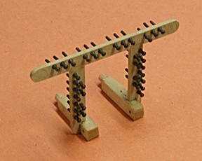
To cut the process easier, I decided to have the fife rail (sans belaying pins) and the two riding posts be one sub-assembly. There are grooves in the posts that matches the rails, so that is why they are held together. Yet, all is 'loose' (no glue yet).
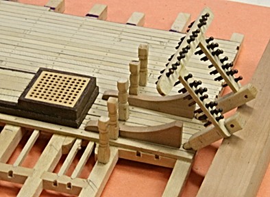
Then this should line up with the five posts as shown. At this point they will eventually be glued together.
PS. The foremast fits between all of this too, I hope.
-
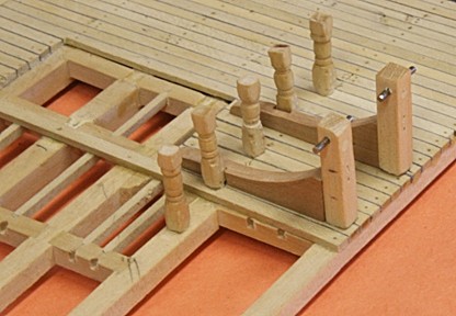
Some more details about the fife rail. All is still loose, including the steel cleats in the riding posts. I tried to use square pieces here, but gave up in favor of something more stout. After the actual rail with the belaying pins, and the cleat/sheaves on the side of the riding posts are done, I intend to make this a sub-assembly and stain the whole thing to give it some contrast.
- mtaylor, bhermann, CaptainSteve and 4 others
-
7
-
Thank you JS. I have copies of those drawings. They are not of the current Connie, but interesting.
I am still plugging away drawing cross sections on the basis as I see things now. That includes some guesses about the size of the fresh water tanks and inside layout of the powder room. All other details come from my full scale model drawings and the side views I have.
Meanwhile, I have made the five posts for the forward fife rail. These will be glued in place during the final assembly. There will be two more 'posts' or riding bits along the right edge. They will also have round ends to fit into the deck planking.
-
Just a suggestion about tapering the aft planks.
When I got to that point I decided to use a small wood-plane mounted up-side down in a vise. I then shaved off what I did not want from the planks. A bit of sanding helped, of course.
I found that even if they are not all tapered the same amount, it does not show in the long run. The main thing is that they fit together.
You can calculate the amount of tapering, but in the long run it is still a hit and miss situation. The eyeball is still your best guide.
One more thing. Keep the plank next to the waterway constant (in width) and don't end up with a sharp pointed plank at near the stern.
- thomaslambo, CaptainSteve and GLakie
-
3
-
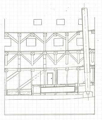
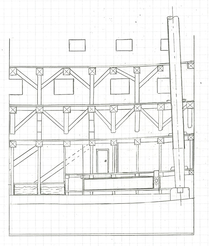
Here is the same picture with some IDs. I added the door to give this thing some perspective.
It still leaves me surprised that the magazine or powder room is as low as it appears to be. My only guess is that they wanted the floor to be well above the keel and its moisture. Yet, in the aft magazine there was no concern along that line (according to the pictures I have seen).
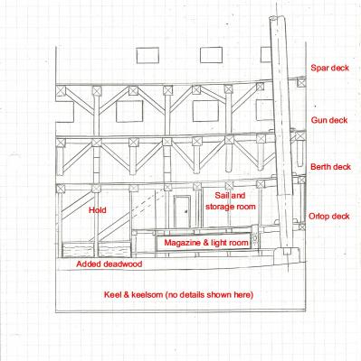
The hanging and standing knees you see on the gun and berth decks are as they are now on the ship. I had made numerous C-knees (as I called them) for the berth deck. But it turns out that for this part of the ship I only need two on each side.
Back to bed and a long drive this morning.
- Canute, GLakie, CaptainSteve and 4 others
-
7
-
Really a challenging project Jay. I agree: can't wait to see her.
Challenging it is, Dave.
I don't mind doing the small stuff such as making the stove, but to re-do the drawings and decks that I have built thus far is a pain.
I keep finding details I was unaware of before, so I am also making new drawings such as the side view and cross sections. These will be my interpretations and may not correspond to published data (or lack thereof). They will be a composite of what I now understand. An example is the raised keelsom and the sections next to that. I will show you what I have in mind after my vacation (leaving tomorrow morning).
I couldn't help it, but I finished a rough draft of the side view as I see it. No labels. And that is not a swimming pool in the basement, it is part of the 'fresh water tanks' made of lead sheets.

There are several other additions, but I will go over that later.
-
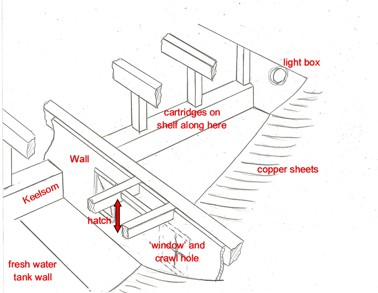
Here is my first interpretation of what the forward powder room or magazine would look like on my model.

1. The beams as shown in the Navy 1927 drawings would have carlings and ledges framing the scuttle or hatch(s) to the first stage, the 'transfer room'. I use that term based on the sketch supplied by Jonathan.
2.There will be a wall separating the transfer room to the powder room. There is a small, hinged window that Henry showed. However, I am not sure if it belongs where I show it (one side or the other). It should be big enough for a small man or boy to crawl through (no other entry).
3. The ceiling of the powder room will have a solid sheet of copper and the rest of the structure will also be coppered, including the posts (just like the magazine in the aft section).
4.The two 'rooms' will be interconnected but not easily crossed. The height between the top of the keelson and deck above will be only a foot or so.
5. In the center there will be shelves for storage of empty and filled cartridges and perhaps a small keg of gun powder for 'repair and balancing' the cartridges. There is no way to bring 100 pound kegs here, so the main filling will be done aft (just like Mark suggested).
Keep in mind that in both rooms the ceiling height is only about three feet.
The part that says 'copper sheets here' will not be there. This will be one section where the frames and beams will be cut away to show the interior.
- keelhauled, bhermann, Canute and 1 other
-
4
-
Dan, the general notes mentioned by the Navy is also interesting because there is a significant difference in the height of the keelsom in the various drawings I have seen. A build up of the keel and deadwood, at one time or another, would explain why the forward magazine is as low as it is now.
When I started this model I followed the layout of the frames and keel as much as I could. But I did not go very far with the inside of the frames. Now I realize that I will have to add more to the keelsom and deadwood than I was going to. Good thing I stopped because now I know that I can show the magazine, fill station and other details as I see them now (as well as on the drawing you supplied me).
Here is where I stopped. Notice the extra material for the keelsom. I had no idea at the time what I was in for.
- Erebus and Terror, GLakie and Canute
-
3
-
Thank you Dan. As I said in one of my comments above, I am going ahead with the information as I see it.
I have made repairs and, after my vacation next week, will proceed with new vigor.
Do you happen to know if the Navy in 1927 created any drawings other than the plan views? I would dearly love to see a side and/or section view. But, again, if they are not available I will create my own. The one you sent me is very fuzzy when I zoom in.
-
You still don't understand. The information (old drawings from 1812 or what ever) you provided me clearly showed that the aft riding bits were in a different place than what Marquardt shows. As a consequence the oven, chimney and two hatches were also in the wrong place or eliminated.
I am not going to rehash all of this, but you can reread all my comments earlier. I will leave it that.
-
Jay -
That clears up my confusion - you refer frequently to Marquardt as being "wrong" where what you actually mean is that he is not showing the modern structures. My sole intent in the comment above was to point out that Marquardt wasn't wrong - he is quite accurate for the period he was portraying.
Marquardt was and is wrong with his drawings by putting major pieces of equipment in the wrong place and eliminating hatches on two decks. You may find that of no consequence but to me that was a major mistake and cost me lots of time to correct.
You mentioned in one of your posts here the following to me (and I quote you): 'If you doubt the Marquardt drawings, find better sources yourself'.
I have done that and they are called Henry, Jonathan, Dan, Google and more. So, no more nasty remarks, please. At least, not on my build log.


How to make best use of your milling machine. Tips and techniques
in Modeling tools and Workshop Equipment
Posted
I like to respond to a couple posts regarding using my mill for drilling.
I understand that cranking the z direction feed can be a pain. I did not realize that some mills don't have the feature I have on mine. That is, with a simple push of a button I can change the z feed from cranking to a lever action such as used on a drill press. In other words I can readily change my mill to a drill press.
In addition, I can mount a dremmel like tool on the head and use it for drills down to the #80 size while indexing the x and y according to my needs. Like most other operations with tiny bits, I just have to be more careful with the feed rate and not move the table while drilling. One example that comes to mind is drilling hundreds of small holes for tree nailing deck planking.
As far as I am concerned, I agree with John that a Vanda-Lay mill seems like a waste of time and money when you consider its very limited capabilities.