


Modeler12
-
Posts
1,716 -
Joined
-
Last visited
Content Type
Profiles
Forums
Gallery
Events
Posts posted by Modeler12
-
-
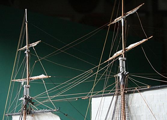
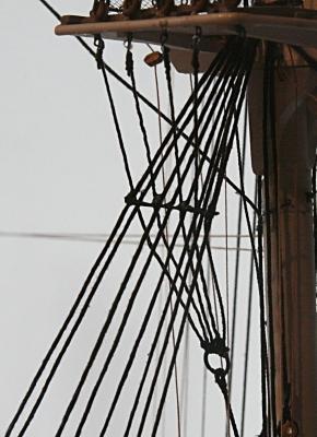
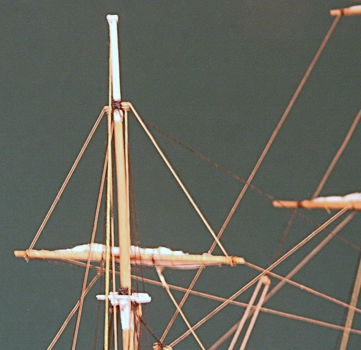
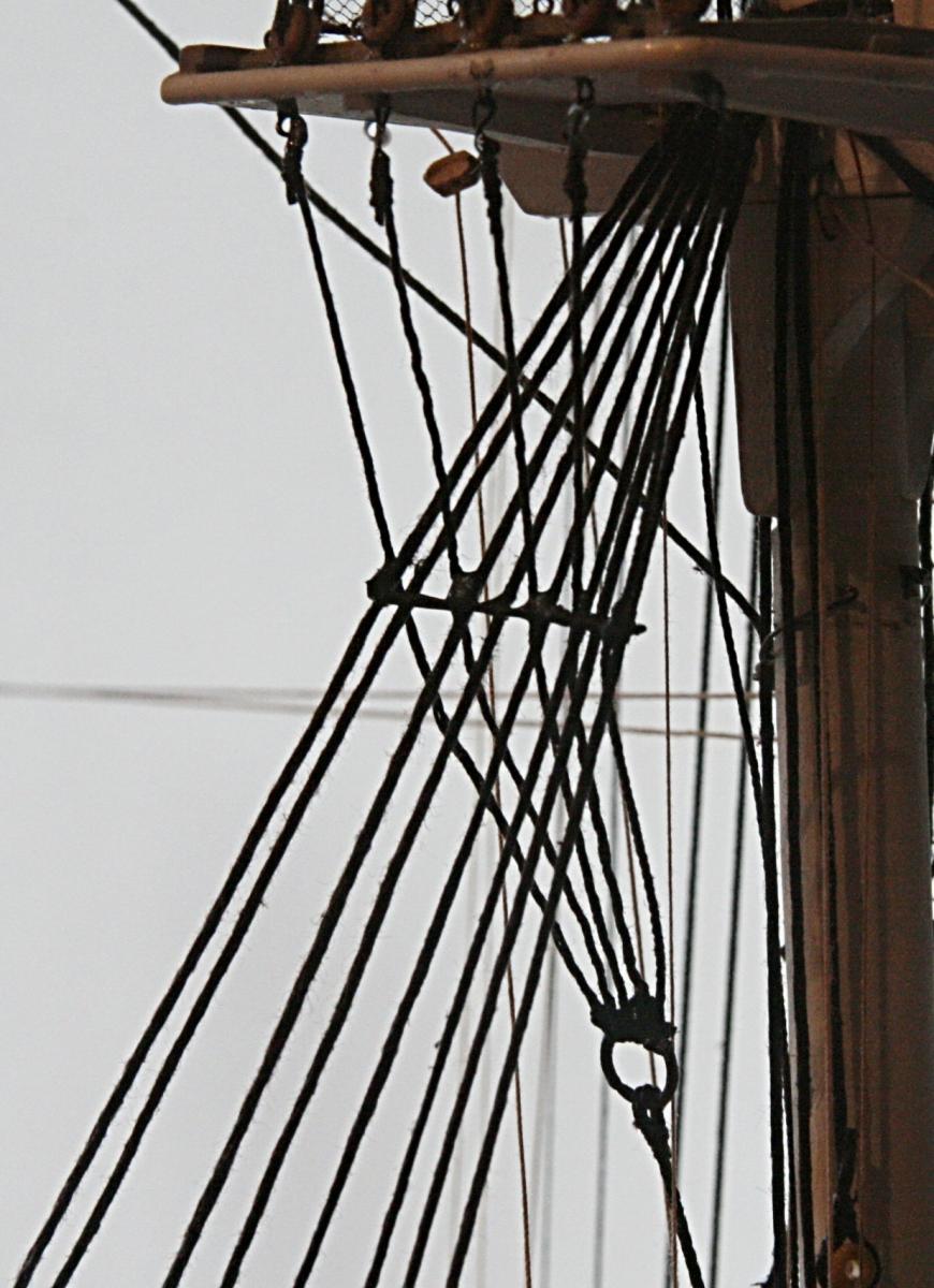
Well, Henry, like I said, I will be adding those lift lines per your suggestion.
Here is a start
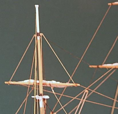
This looks much better than the royal on the fore mast below. That poor guy didn't get a lift yet.
I must admit that at this stage I am taking a few shortcuts (cheating actually) and hide the 'belaying points'.
As you can see the 'blocks' on top are actually bullseyes; they are really the same size (camera angle I guess).But now I have to finish what I was doing before on the fore . . . . ????
-
In my opinion, it is a mistake to not include the lifts. They are a major player in the control of the yard. You would not want to have uncontrolled up and down movement of the yard arms putting strain on the sails and gear.
Henry, I had some more thoughts about what you said and decided that after I am done with the fore topsail I am going to try to add at least a few very visible lift lines.
You were so right and my plans so vague at the time I started this project. The drawings show a loose line hanging from the spars (as if they were an after-thought, perhaps). My mistake. But your explanation brought me back to what the whole sailing thing is all about.
On my model the royal and topgallant spars are furled and lowered. This would be a good place to start adding lift lines. They would look appropriate. In fact, the lines can go to some some 'blocks' I already have up there (maybe as a premonition at the time I glued them in place). It would be difficult to properly install lift lines on the three topsails. They are busy enough. I will consider doing it with the lower jacks later.
I don't know if there are good explanations about rigging and what and what not to include. I am a bit of a maverick and don't follow instructions very well. Hence, I have not read up on this whole thing before I got started on the rigging, but I learned the hard way. Now I am smarter, but not yet smart enough.So, my friend, thanks for this honest and valuable remark.
- popeye2sea and CaptainSteve
-
 2
2
-
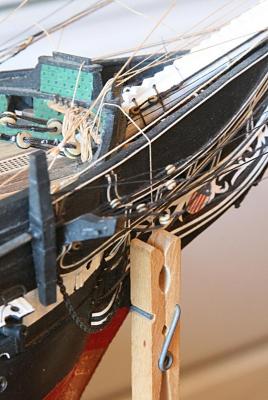
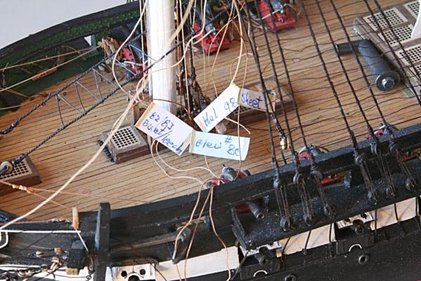
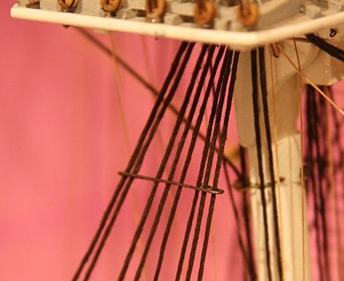
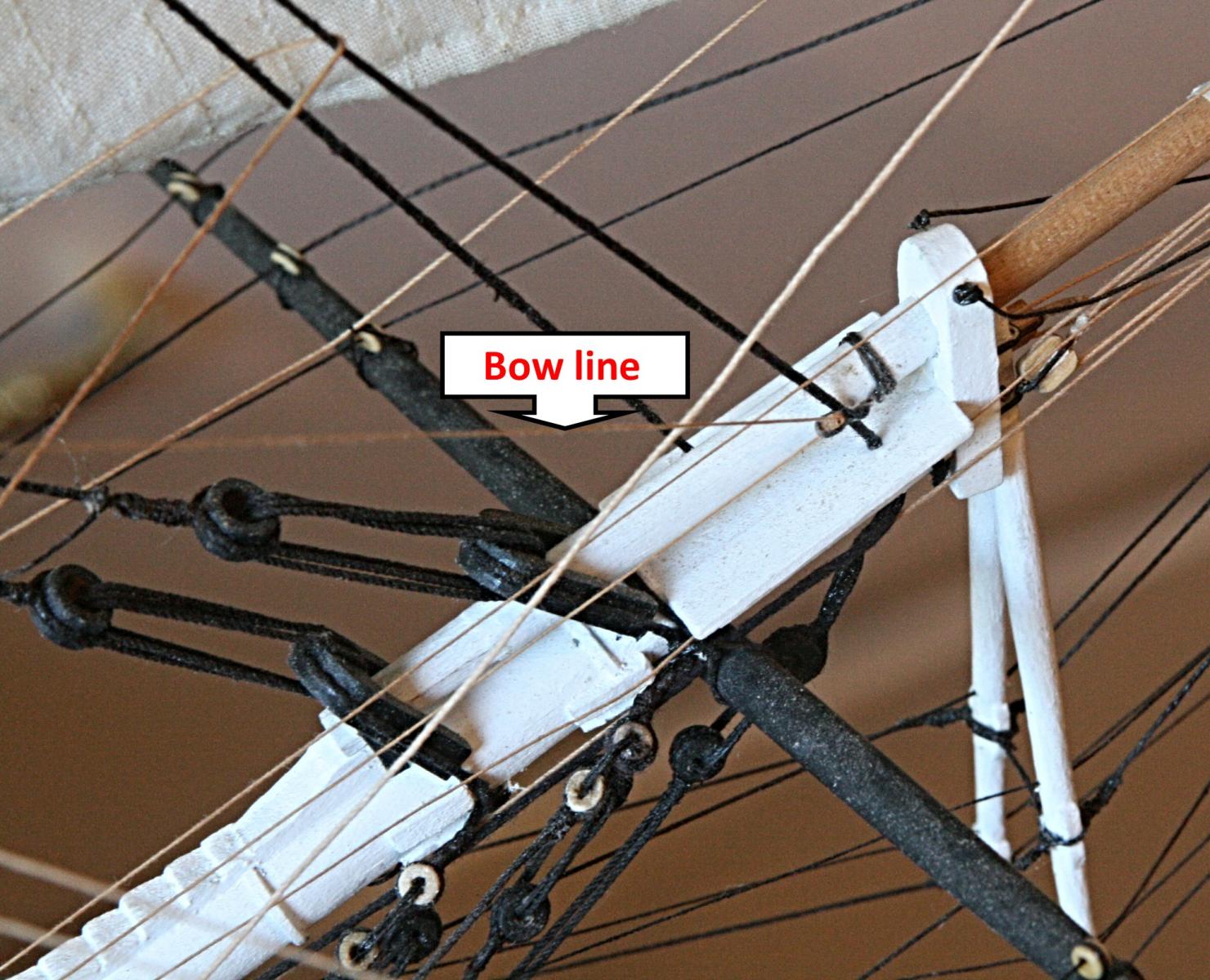
Here is an interesting one. It is the bow line (fore top sail again), the line that pulls the sail leech forward.
From the three sections at the sail it goes forward to a tiny block on the bowsprit. Then it goes to the left of the sign in the picture below, is threaded through the guide on top of the rail to the fife rail. The second picture shows the thin line after I looped it around a belaying pin. The clothespin is to hold the line taut until I am ready with the final setup.
The little blocks (p/s) were installed more than a year ago and I finally got to use them. In the pictures below the port bowline is not yet threaded through.

- CaptainSteve, dgbot, Geoff Matson and 2 others
-
5
-
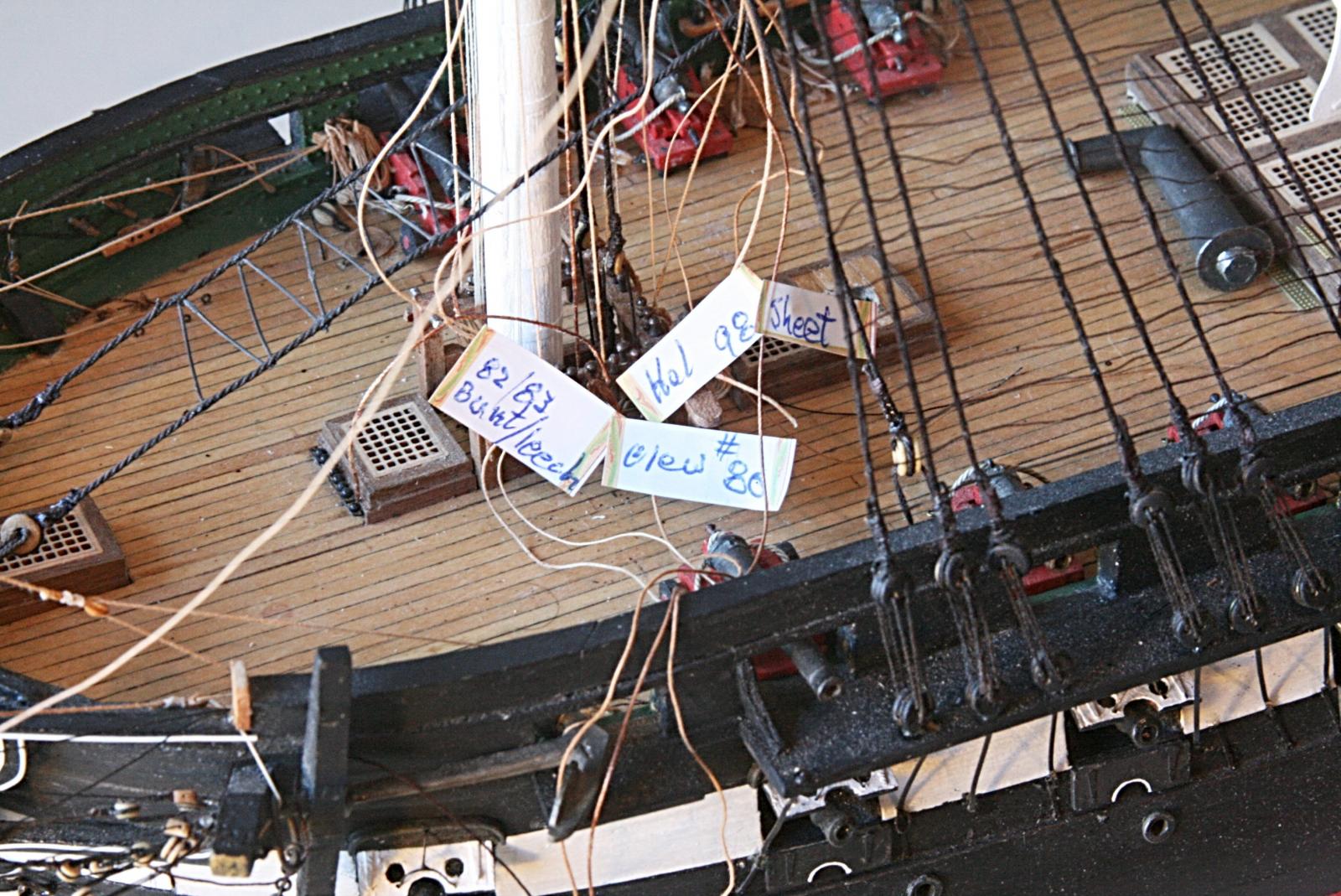
Rigging the fore mast topsail.
Pulling the lines from the sail up through the blocks and then down to the deck might seem relatively easy.
The problem is that I loose track very quickly what line is where. I take them one at a time and when it reaches the deck I put a small piece of tape on it along with the cleat number per the rigging plan.
Notice in the picture below that most of the lines have to go aft of the jack. On the port side this gets to be a bit crowded. I cannot tighten the lines too much until the starboard side is done and the whole thing is raised to its final position. Then all lines will be belayed.
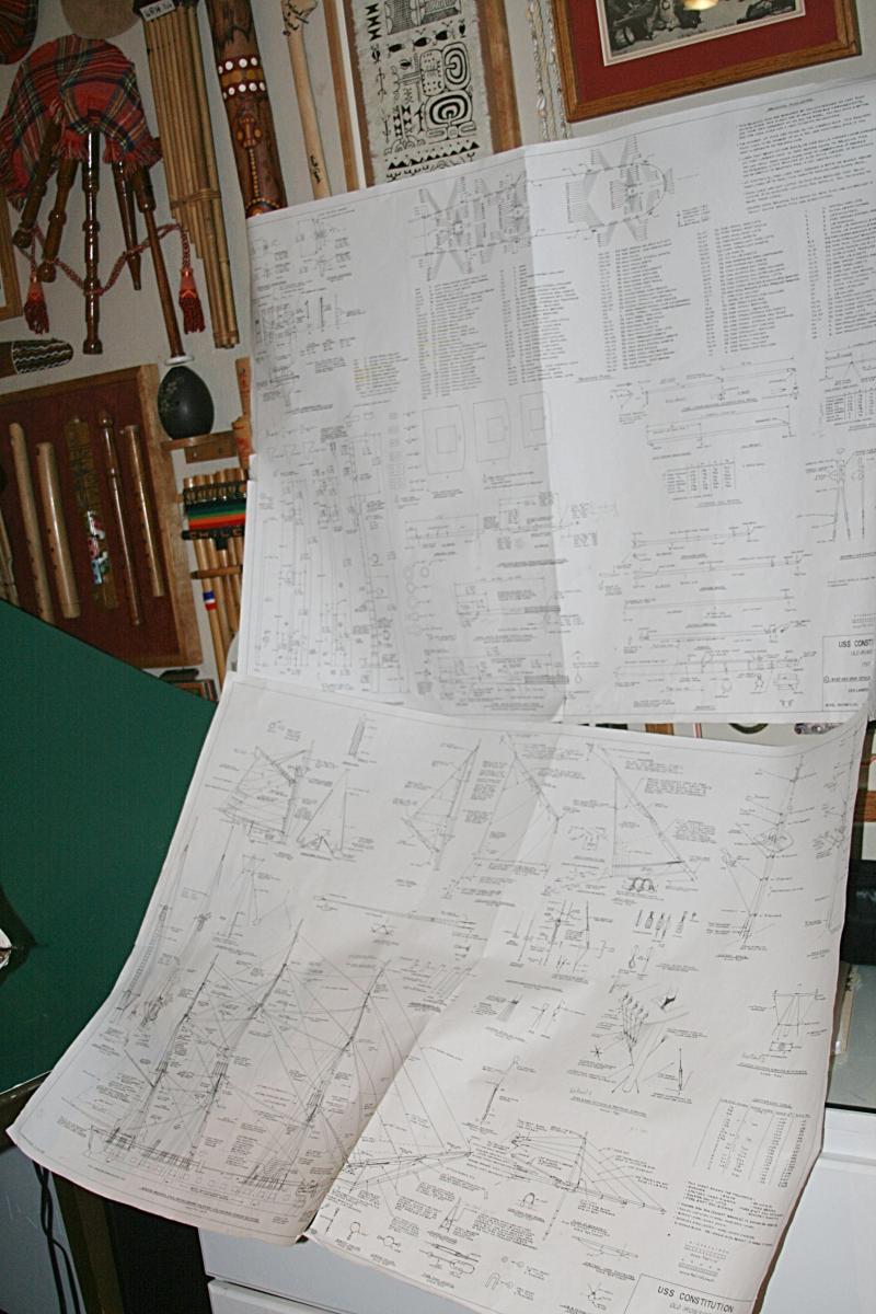
I have to refer to three large drawings (#6,7 and 8).
One lies on my desk; the other two are taped to my collection of 'junk' from around the world. One corner is taped to a didgeridoo (next to a bamboo harmonica from Thailand and a bagpipe from Scotland). I have about twelve flutes from Europe, Hawaii, South America, China, etc.
-
Thanks again you old salt. Big help. Mostly because I am curious and sometimes not able to correct. I still want to come back to Boston to see the old gal as she floats there now.
Here we go with installing the fore topsail. I will try to take lots of pictures just for file and those interested.
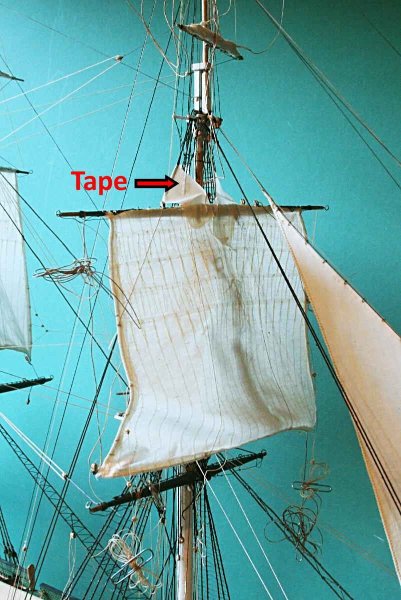
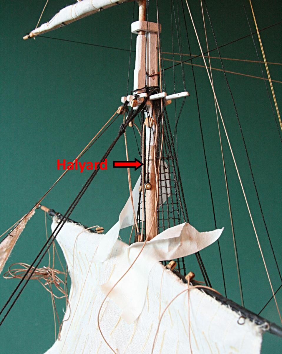
The first thing I did was to make a few 'repairs' such as loose reefing lines on the sail. I also forgot to install a block on the spar right above center. When all looked OK, I held the whole mess up against the foremast and taped it in place well below its final resting spot.
Then I pulled the halyard line through the block underneath the top, then through the one on the spar and again through the block on the other side. It may be hard to see because of the other lines in the picture. But the idea is that the line goes from one side, through the spar block and back through the block on the other side. The line draped across the sail is the port side halyard. Then the two lines will go to the fife-rail below. They will be the lines that raises the spar and sail into its final position.
Notice I pulled back on the tape to get to the block on the spar.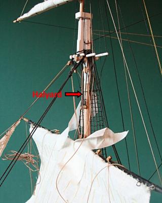
But before I do that, I will hold the spar with the masking tape and run the other lines through the blocks above.
But now I have to make dinner. More tomorrow.
-
In my opinion, it is a mistake to not include the lifts. They are a major player in the control of the yard. You would not want to have uncontrolled up and down movement of the yard arms putting strain on the sails and gear.
Henry, you are absolutely right about lifts being a major player. But early in deciding what I was going to include with the sails, it seemed to me at the time that the lifts were not that important while sailing. I was wrong, but there is no way I can add them at this point. I don't want to add them to the fore mast sails only.
What about the braces, Henry. Was I wrong about the fore jack braces? I cannot find a good picture of the ship as it is rigged now. Are the lines that thick, and attached at both ends to the main stay (or a futtock shroud as the plans show)?
-
One more brace to go. But the spar to which it goes is attached to the fore topmast sail. I still need to install and rig that sail. It will be the last of six.
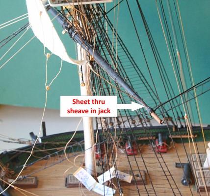
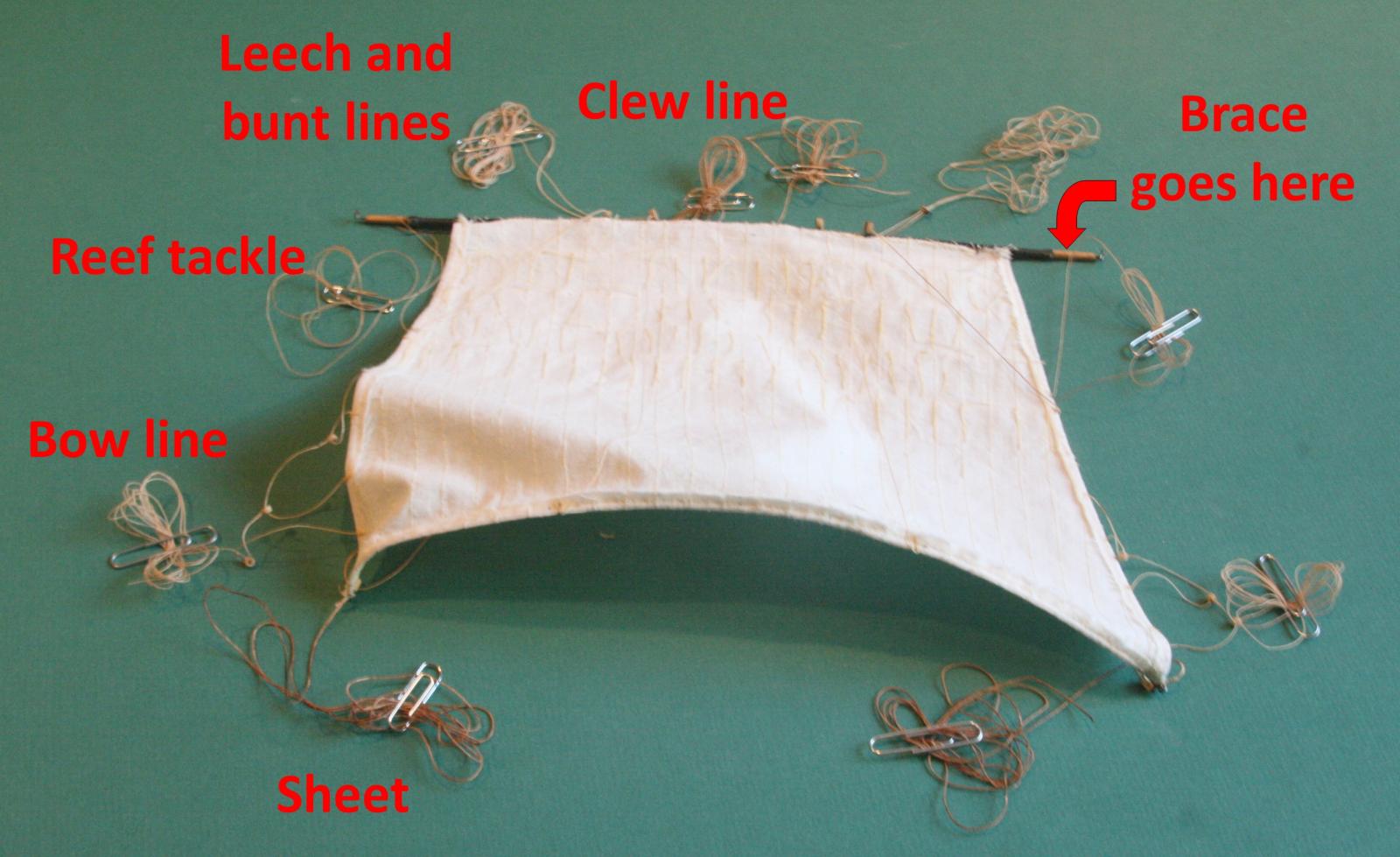
Before I do, I need to refresh my memory what all those lines are that were attached to the sail eons ago. What are they and where do they go? The picture below should help. There are two sets: s/p starboard and port.
From the bottom up:
1. The sheet is used to control the set of the sail depending where the wind is coming from. The heavy line goes from the bottom clew down and through a sheave in the spar or jack below it. It takes a lot of force.2. The bow line is used to pull the leech or edge of the sail forward and control its shape. It goes all the way to the bow sprit.
3. The clew line, leech line and bunt line are used to haul the sail up and furl it. Each line is attached to the sail as shown. The bunt and leech lines share a double block that is attached to the top above. The clew line goes through a block on top of the spar and then down to the deck. All three are slack when sailing.
4. The reef tackle is used to haul part of the sail up and secure it around the spar with the reef lines that are sewn into the sail. It is used in strong winds when the sail area needs to be reduced. The line also goes to a block below the top.
Not shown and not used by me are the lift lines. They would be used to raise the spar or tilt it when needed such as in tight quarters in port.

- Ol' Pine Tar and GLakie
-
2
-
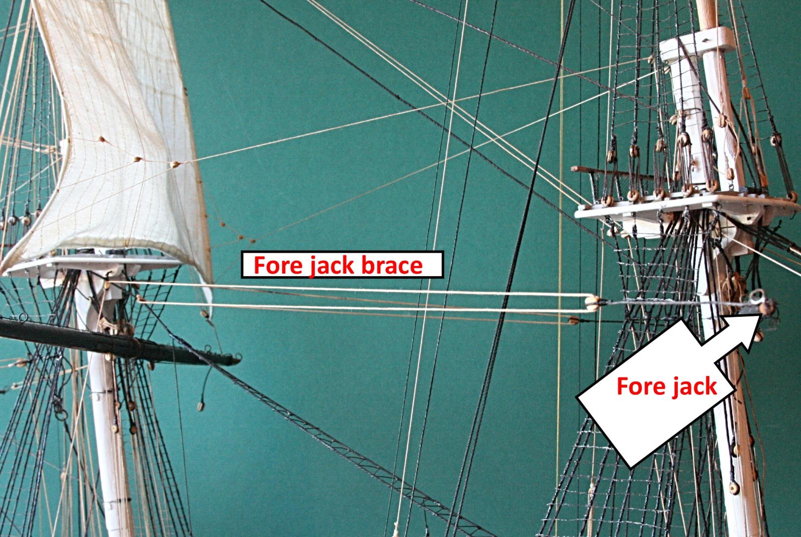
A picture is worth a thousand words. Maybe two pictures should be worth more or less?
The brace is the horizontal line tied at one end to the main stay and the other end goes to a pin on the deck. With the block underneath the top, all now has a clear line of sight.


-
More comments about braces. Please bare with me
 . This gets confusing and drawings would help. But let me try with words.
I mentioned how the braces for the mainjack go all the way aft. Now come the braces for the fore jack. A whole different story.
The plans that came with the kit show that the braces start at the main stay near the main mast. They go through a block near the tip of the fore jack and back towards the main mast. So far so good. Petersson shows the same thing, but Marquardt in his book shows that it starts from an eye bolt in the topmast cross-tree.
When the line comes back, Petersson shows the line going through a block on the main stay and then further back to the deck below where it is belayed along the railing. When I looked at this, it seemed to me that when the main course is set, it would interfere with these braces. I don't like that. Even though I am not including this sail.
The plans with the kit shows a similar thing, but they also added another block that is tied to a futtock shroud and then down to the deck. This solves the problem of interference with the main course, but brings up other problems.
Braces are a major means of transferring the driving forces from the square sails to the hull. Without them the sails would bellow forward and drag the jack out of wack. So, the braces are thick and strong. In fact, the plans call for lines that equate to more than 1.5 inch thickness. That is too much, in my opinion, and I reduced that to about one inch.
Even so, to have these braces tied to a futtock shroud is not smart. When you vector the forces involved, the stresses are too much for these shrouds. They were intended to hold the topmast in place, not to drive the ship forward.
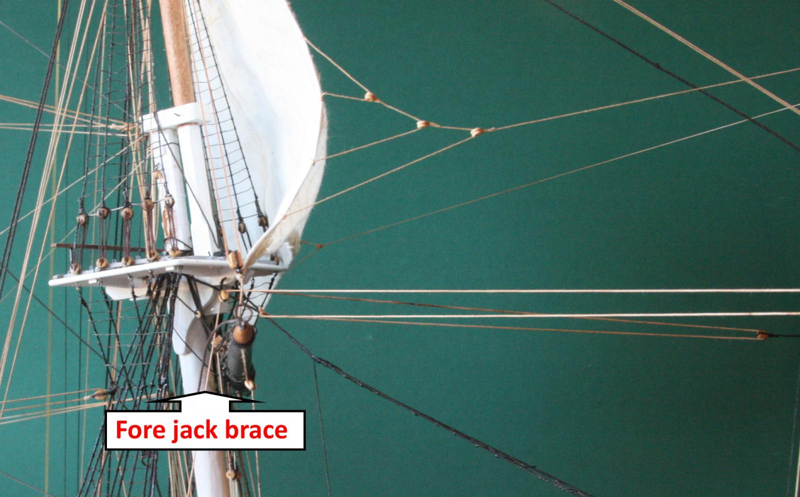
My approach is to have the braces come to a block tied to the cross-tree on the main mast. Hence the combination eye bolt and block I showed above. This is a bit of an afterthought and the spot was hard to get to on the port side. But it worked. Now I have the clearance for the braces to go down at an angle to the belaying pins on the bulwark.
I am curious how others have solved this issue.
-
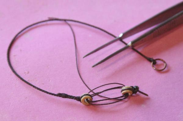
Sometimes I cheat.
There is a bit of difference of opinion in the way some of the lines are attached. For example, the drawings that came with the kit shows how the main yard braces are attached to the main stay one way while Petersson shows it another way. In either case I had to add some blocks that are hooked to another eye bolt. Nothing new; it has been happening a lot. But in this case, the installation of the eye bolts was hard to get to.
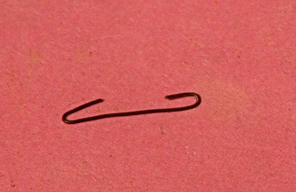
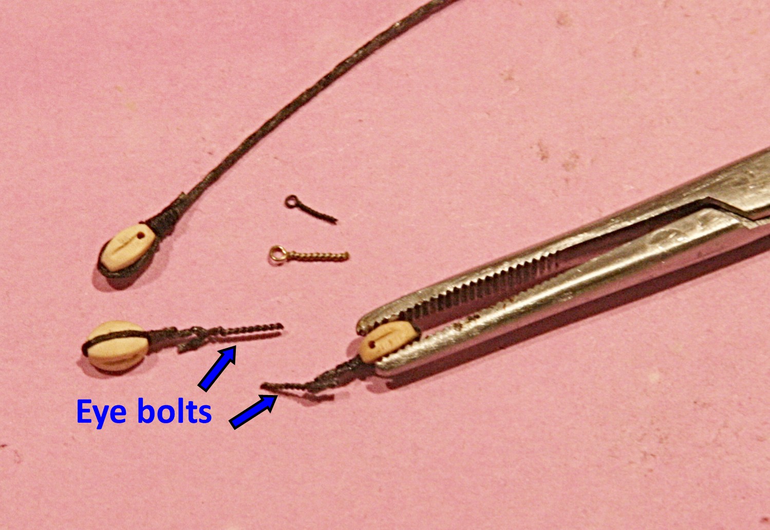
Instead of drilling the hole and installing the eye bolt with epoxy first, I decided to pre-assemble. The picture below shows how.
I took the block and added the black strop. I then hooked it onto an eye bolt (the type made by twisting wire around a pin!!!). I coated the black line with CA and let it set. Then I was able to bend this line to simulate a wire hook. Now the whole thing is rigid and should be easier to epoxy into the hole where I want it.
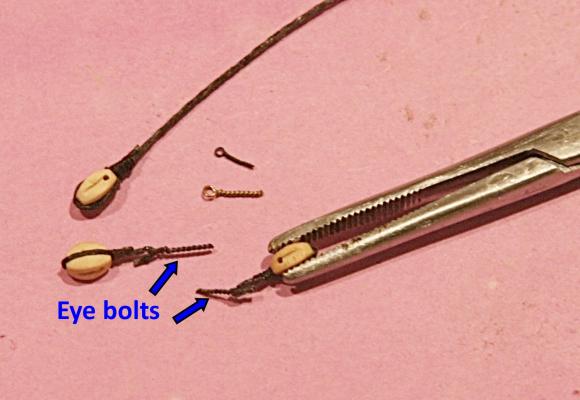
While the thought lingers, this might be a good way to install the cannon rigging, the part that goes to the bulwark.
For now the frigging rigging continues.
- CaptainSteve, Ol' Pine Tar, dgbot and 1 other
-
4
-
Rob,
Nice crisp shots. And I second using a tripod.
I third using a tripod.
In my opinion the camera is really secondary (except an iphone or similar). Almost all decent digital cameras give you some options about aperture and all that stuff. But in the long run (after you know how to use the one you have) it is the nice, long exposures that usually give you the best results. Hence, a tripod.
-
I've been reading your last updates. Looking good. Just one thing I came across a few times. You use CA to fix some parts of the rigging (like e.g. ratlines). As far as I learned and know CA will eventually deteriorate the threads, thus in time your rigging will break/fall apart at those spots. Usually white glue is applied (often diluted)
Please correct me if I'm wrong
I have heard about this but never experienced it. I still have some old 8mm film that was spliced with Eastman 910 almost 50 years ago and I have not seen it fall apart. True I don't use the film anymore, it just sits in a box. But that will be the case with my model also (if I finish it before the fifty years are over). But by that time I will be in a box.
-
Jay:
Is there a number on those cutters someplace? It kind of looks like these: http://www.micromark.com/End-Nipper,11459.html?sc=WGB&utm_source=GoogleBase&utm_medium=feed&utm_campaign=GoogleBase&gclid=CjwKEAiAlvilBRC5ueCzkpXb4kgSJADxop1B6UrKveQVj0IjXfKeIuOq2NZvsEqh7maL48ctSWBF3xoCwv_w_wcB at Micro-Mark
Cheers

That's the one. Thanks George.
The picture in their add explains it all. But the price is still enormous.
I am glad that I have a rich mother-in-law.
-
I corrected my mistake and now have a couple more braces in place. All that means is more confusion about what line goes where.
Even a spider would have nightmares.Suggestion: If any of you are considering adding sails to this model: don't. It can lead to . . .. . .
But it is fun for me.
- GLakie, CaptainSteve, hexnut and 2 others
-
5
-
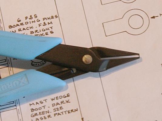
More than a year ago my mother-in-law bought me this end snipper. I am trying to find out where it came from. I know it was not cheap, but a friend of mine is interested for circuit board applications. It is made by Xuron but even their website does not show it. Does anyone know where to buy this?
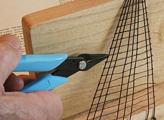
It cuts thin wire or lines flush by holding it right next to the surface. The ends of the 'pliers' are bent and sharpened, so the cutting action is perpendicular to the handles. I use it from time to time to cut the ends of lines to get rid of that little excess as shown below. There are lots of other applications, but it is not intended to cut thick metal wire.
-
Have any of you ever made a mistake?
I finished the fore shrouds and ratlines on the starboard side. Not pretty, but it will do.
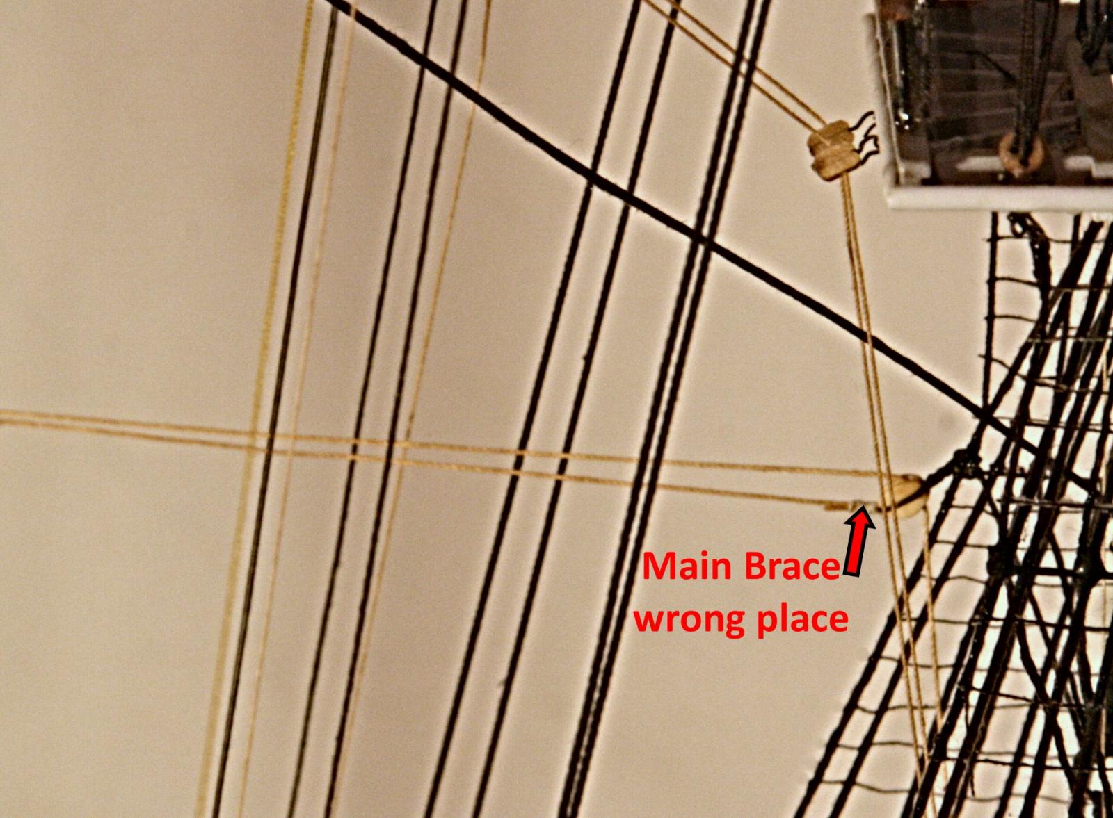
Then I was about to add the main brace; like I had done on the port side. The brace there goes from the spar forward and is latched to the fore-shroud at the futtock stave. See picture below.
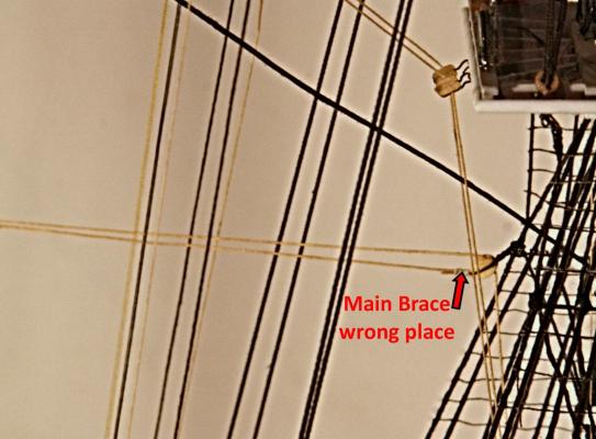
Mistake. I had blindly followed the same rigging that was done for the mizzen spar and 'assumed' the same would be true for the main and fore mast braces. To find the right way I had to refer to the drawings (#7 in the series) and also the book by Lennarth Petersson 'Rigging Period Ship Models'. The second picture below is from his book and shows where those braces should go. Notice also that the topsail braces also go aft.
I will detach the port brace, but will hold off with adding these far-out lines until much later. Meanwhile I do have to add 'sheaves' in the side of the hull far aft.
The reason I want to hold off is that I want to see how these lines might 'interact' with the davits and whale boats that go into the same area. Besides, braces are easy to get to, except for their belaying points.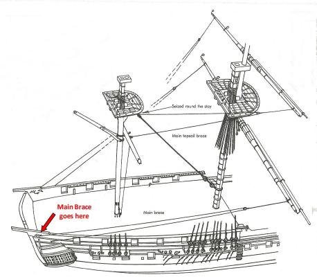
Suggestion ------------ # what ever.
Don't assume.
-
If I may interject.
I had no idea that this would result in a nice 'conversation' about CA, but it is good to know that some (like Mike above) have had positive results and are not too concerned with the durability of CA in the long-run. After all, I don't think our usage involves high stresses (or do they?).
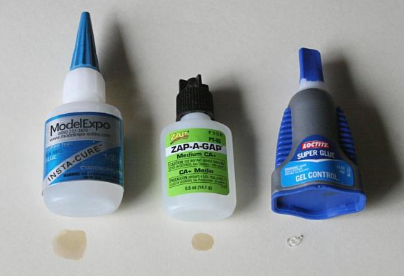
By the same token, I am not surprised about having several who like Locktite adhesives, but I am wondering about Zap-A-Gap. I should not a proponent of either of them, but I did return a container of Locktite's marked 'Professional' that showed a model ship on its cover. At the time I decided that was for me???? Wrong!! As far as I am concerned it was the same very low viscosity stuff I can get at half the price.
But I have had a learning and good experience with the green bottle of Zap stuff. So be it.Is price a object? Not in mine opinion. I think we spend a lot more on new tools and other materials than we do on glue!! How much CA do you use on a model? Let's experimentation be separate for this comparison.
Is it true that many of the cheap 'Super Glues' work just as well as those sold by our hobby suppliers. In fact, I will do some more research with your help, please. But again we should be careful about what 'works well for us'.Here I my take.
If you like what you are working with, fine.
If you want to experiment with others, good.
If you want some advise from others on this forum, better. The more the better.
Either way, the application, more than the product, should be the guiding factor in the selection.- mtdoramike, Tuffarts and dgbot
-
3
-
Hi Rich,
Perhaps I'm a bit late on this but here is my method for making eye bolts and oar locks. Got this
from a fellow modeler who makes hundreds of these as all of his models are scratch built. Most
of my eyes are from .010 brass wire. Hooks are made from brass wire of different diameters
depending on the eye size needed.
John Elwood
Pardon this comment on your log, Rich, but this is indeed a nice version of making oar locks.
I have made eye bolts this way using steel wire down to .010 inch, but never thought about cutting away part of it as shown. Chuck and others gave me this idea about a year ago and here we find a great expansion of the same theme.
Rich, I have just gotten back to the forum and looking over what is happening. Yours is fabulous.
So much to learn!!!!
-
I am sure you are all well aware that there are several brands of CA adhesive on the market. I am curious which you prefer.
Here is my view. The formulation of this rapid curing adhesive dates back to when Harry Coover working at Kodak developed and used it to splice movie film. I remember using this as Eastman 910. Loctite came into the picture and made its own version. Since then there are several more, but (to the best of my knowledge) they all depend on the same chemistry.
However, what I found is that for my use in building models I rely on three types depending on its application and viscosity. The original Eastman 910 was very thin (low viscosity) and was good for smooth surfaces (such as movie film). This is the case for most on the market today.
I have been using a somewhat higher viscosity type called Medium CA by Zap-A-Gap. It is good for most applications such as threads, cloth, wood and other porous materials.Then there is one that has lots of fillers and has high viscosity. It is referred to as 'Gel Control' made by Loctite. it is good for making those 'knots' on the rat lines shown in an earlier post. It has good gap filling properties while still bonding pretty well for most bonding jobs.
Here is are the three I referred to:
-
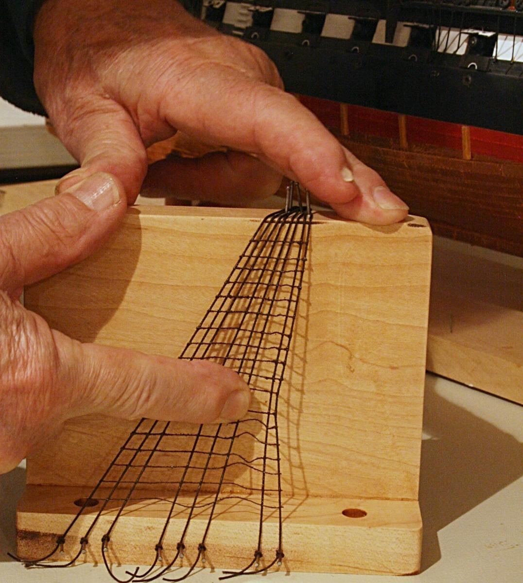
After the mock-up sat around for a couple days and the adhesive had really cured, I was curious what would happen if i punched or forced my finger into this rigging.
I could distort the webbing and ratlines, but they would not come loose. At least with what I considered rough treatment.

I will have to try this on a real model, like my USS Constitution . . . .
-
Harvey, we should both owe an apology to John Bentinck.
We both spelled it wrong, which was probably not unusual with him, his family and the times they lived in.
But his contributions to the British Navy were good and well remembered.
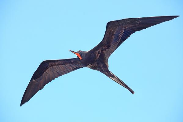
I just wished he could have put those darn shrouds of his in a better place to get to.Here is another frigate that does much better at sea and land than any of ours. And we had nothing to do with its design.
-
Jay, I just came upon your log. Sorry I did not see it sooner. If I build the Conn your build will be a must read. I however lack the courage and I am looking at other models of interest. Great work
David B
Thank you Dave, but remember: nothing ventured, nothing gained. Although this lady is a tough one to master.
Here is a picture of the last Bentnick shroud installed on the starboard fore mast.
Now what I need to do, of course, is to add the rat lines. The more I think about those, the more I am inclined to use the contact cement approach I posted somewhere else. I took the little mock-up I made and could punch the ratlines/shrouds with my thumb pretty hard without damage. It is a tough setup.
BTW I still have to trim off the ends of the metal futtock stave.
As a retired engineer, I really like the idea that Bentnick proposed and used to transfer the loads on the futtock shrouds to the deck via this extra shroud. What it does is to eliminate (reduce) the stress on the two other approaches. One being where the futtock shrouds are tied directly to the main shrouds, the other where the futtock shrouds cross over to the other side and again are tied to main shrouds which already have to carry the brunt of sideways forces on the mast. If the main shrouds were designed today, the extra forces imposed by the upper parts of the mast (via the futtock shrouds) would mean much thicker and stronger shrouds than if those extra forces (stresses) were carried elsewhere.
Anyway this is an old engineer rambling on.
- capnharv2, CaptainSteve, WackoWolf and 2 others
-
5
-
A couple days ago someone mentioned the Bentnick shrouds and how he attached the swiveled bullseys to the bulwark first. It is a real tricky place to get to since the mast and shrouds are all in the way. Here is my approach.
I locate and drill the hole in the bulwark first. Make a dry fit with the swivel bullseye, but don't install it yet. I then pre-assemble the Bentnick shroud with the ring that holds the five futtock shrouds and the tackle with the two bullseyes. However, I leave the tackle line loose. It will be tightened after all of this is installed. The shrouds are added to the ring and the whole thing is carefully fitted to the bulwark.
In the pictures below you can see the swivel (which will hardly be noticeable) and the ring which was silver soldered at the joint (barely see the light spot). I should have blackened this copper ring, but will touch it up with some black paint. The two bulleyes were drilled out to represent the real thing as shown in the pictures taken by Popeye2sea.
- GLakie, GuntherMT, Geoff Matson and 2 others
-
5
-
Suggestion 15
Stabilize and hold the shrouds in place before adding ratlines.
Of course this is something I am going through right now, so bear with me.Once the shrouds are installed with deadeyes below and the mast on top, there is still some 'movement' or looseness to the whole thing. It is not a stable platform for the ratlines. Hence there is a solid rod (called a sheer pole) near the bottom and the futtock stave upwards. They really hold the shrouds where they should stay. Lateral movement in particular can be a problem otherwise.
To install these bars is tricky. They cannot simply be cut to length and tied in place. Things have a tendency to slip, slide and drop out of place.
What I did is to take the wire, bend one end, determine where to bend the other end and fit it to the shrouds.
Below you can see a futtock stave before and after fitting it to the shrouds.
I then used some thread and tied them in place, followed by a dab of epoxy to finish them permanently. Now I was ready to do the rat lines. If necessary I can cut the ends of the bars if they show too much. Some black paint is also in order.
- capnharv2, HIPEXEC, Geoff Matson and 2 others
-
5


USS Constitution by Modeler12 - FINISHED - Model Shipways
in - Kit build logs for subjects built from 1751 - 1800
Posted
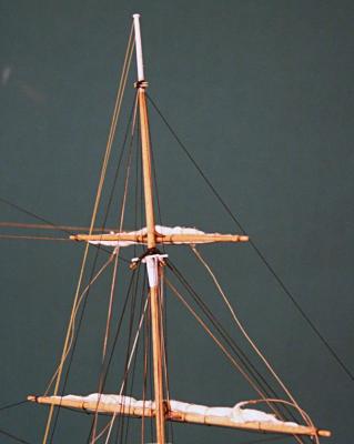
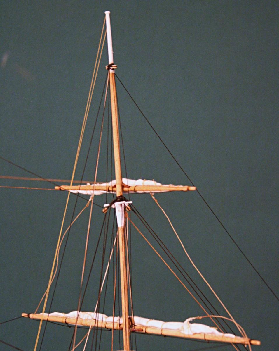
Thank you guys. Indeed the lifts on top really stand out. I will do the same with most of the others, but the topsail would be difficult. Besides the sails would tend to hide the lift lines when viewed from the bow.
Now I will continue and stop when the rigging is almost done.