Modeler12
-
Posts
1,716 -
Joined
-
Last visited
Content Type
Profiles
Forums
Gallery
Events
Everything posted by Modeler12
-
 Like I said above in the last section, I am a firm believer in using epoxy for installing eye bolts and I have never had any problems using that whereas CA glue will pull out if the hole is a tiny bit too big.
 -
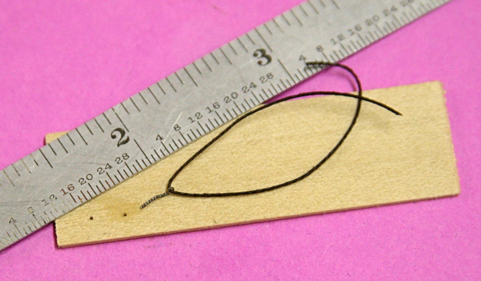
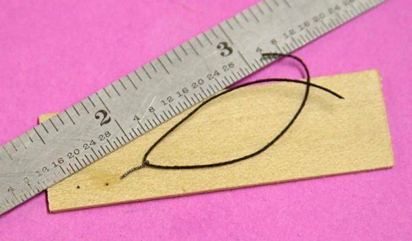
Scaling is always useful to 'judge' if the line thickness (and any other parts) look right. I have been using thread that is .011 inch thick and to my eye it looks OK. Too thick, of course, when I scale at 1:76 it would come to 0.84 inch. I hope that is close enough for Russ' hair.
-
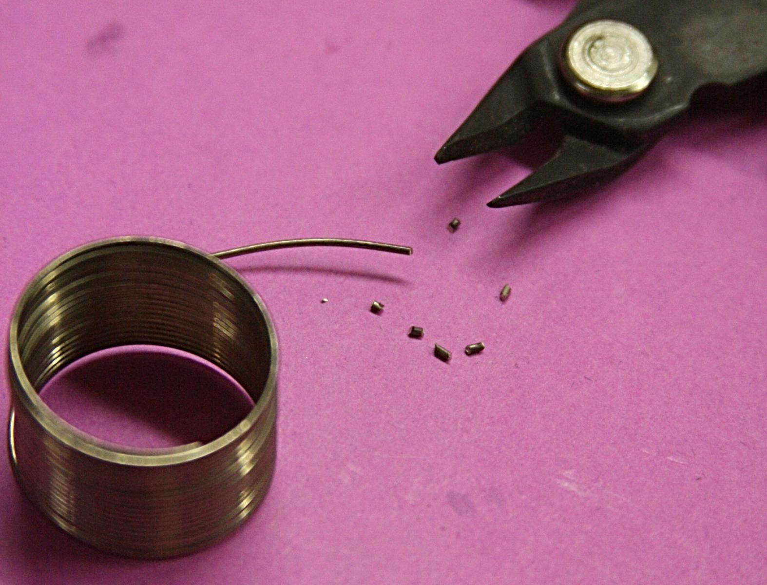
One more comment about these eye bolts (and then I will be quiet, may be). Chuck mentioned that the shaft of the eye bolts made this way provides extra 'pockets' or space for the adhesive to make a good bond. The twisted wire does indeed make pockets, but I am not sure it is needed!!!! Here is my thought: A certain modeler, Bob H., claimed that he never had an eye bolt pull out when he used CA adhesive. I ran some tests and decided that he was wrong or very lucky. Of course, there are 'gap filling CA adhesives', but they don't go that far. When an eye bolt is installed on deck (or on top of a spar) with adhesive (no nut on the back side or any other way) and the line pulls straight upwards, the shear on that bolt shaft has to take the brunt. CA does not do the job. Here is a little test with the tiny eye bolt using CA adhesive. It pulled out of this wood with very little resistance. I have used epoxy. And there are several varieties, but they all do well filling 'gaps'. Even if the gap between a straight shaft and the media wall is relatively large, the 'adhesive' quality of epoxy is usually strong enough. And so is the 'cohesive' property between metal and wood. The difference is that the first, adhesive strength, refers to the strength of a solid piece of glue (in this case epoxy), while cohesive strength refers to the strength between the two media. CA does not have much to offer when it comes to 'adhesive' quality. So, I use epoxies for eye bolts 'and I have never had an eye bolt pull out with epoxies'.
-
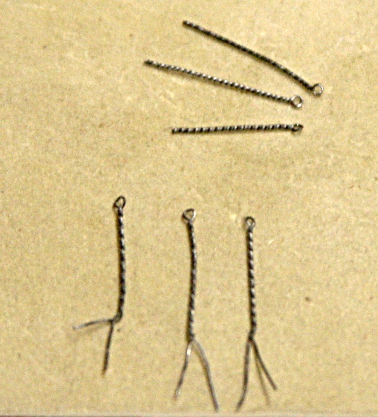
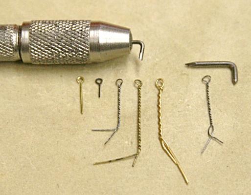
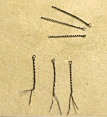
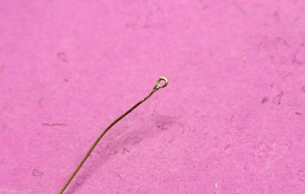
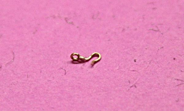
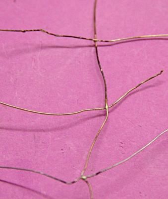
Ulises, post #28 here, showed an excellent way to make those tiny eye bolts. Thank you again. I had to try this and ran a few experiments. I took two steel brats (.035 and .045 inch diameter), made hooks to fit into a pin vise. Later I also made a hook out of stiff bronze wire at .021 inch diameter. Then I used three types of wire to be made into eye bolts. A couple were made of .010 inch steel wire, one was .012 inch brass and one .015 inch brass. I compared the results in the picture below. To the left is a brass eye bolt that came with my Conny kit (and I have not found that available commercially). To the right of that is one I made using needle nose pliers (blackened brass .012 inch thick.). The next three were made using the .035 inch hook and the last one with the .045 inch hook. Incidentally, the eye opening of the 'kit supplied' was .031 inch diameter. You can judge the others accordingly. Then I made some more using the thin steel wire (.010 inch) and the bronze hook). I found that the number of twists made a difference in the final piece. So, I decided to see what the limit of twisting was. Something had to give. Indeed, the wire broke where I had clamped it (my trusty hemostat). I repeated this two more times and found the results to be pretty much the same. The eye diameter was exactly the diameter of the bronze hook. Hence a pretty good gauge. I should have added that in the last picture the three horizontal pieces were the ones that broke at the clamp.
-
Should all spars be aligned in the same direction?
Modeler12 replied to Modeler12's topic in Masting, rigging and sails
Thank you gentlemen for your replies. I was curious about this but, unfortunately, I posted my question after I had already braced the upper yards. Again, the royal and topgallant sails will not be furled nor rigged (other than the halyards and braces) so I gave it no thought at the time. Then, when I started to add the topsails did it occur to me that the upper spars should align the same way. If the wind comes from about three o'clock, the wind shear and resistance should not matter too much, but having the spars facing the same way would, indeed, make the whole picture look better. So be it. I might add that the way I am rigging is from the top on down (good or bad, it works for me thus far, except for this foo-foo). -
I conducted a few brazing experiments with a small and large torch to see how they performed on small and large diameter wire. This video includes annealing metal wire, how to make silver soldered eyes for hooks, and a few other suggestions and tips. In particular, I try to show how tiny joints can be silver soldered using 'pellets' of silver solder. https://www.youtube.com/watch?v=RuMoGam-Mww
-
Homemade Rudder Hinges
Modeler12 replied to lamarvalley's topic in Metal Work, Soldering and Metal Fittings
Indeed, nice work, Randy and Sudomekh. You show that a lot can be done with those details. I am afraid I took the easy way out for my Conny. Since the hinge straps were going to be painted black and the hinge itself would be barely visible, I decided that instead of brass, I would use stiff paper. I actually used an old photograph print, cut it into strips, painted them and . . . .
-
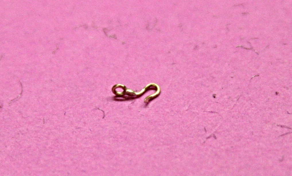
Let me add one more picture of an eye in the same piece of brass wire. I used a very tiny piece of solder and still had a bit too much. One thing I have to be careful with is that I don't get flux on or too close to the eye. It will fill up with the solder very easily. Here is the same eye piece made into a hook. Again notice the excess solder. But a little filing should take care of that. PS Interesting idea Mark. I assume that it would have to be a raw potato, not a baked one. And since this is Thanksgivings Day, I would also assume a yam or sweet potato might work also.
-
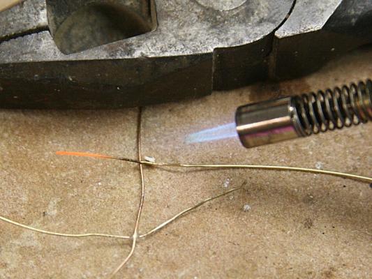
Nirvana touched on using a torch to solder. Here are a couple pictures of a technique I picked up from a lady who made jewelry using silver soldering and a small torch. The pictures show three joints using bronze wire vertically, steel wire at the bottom and two pieces of brass wire above that. The bottom joints were made by using my roll of silver solder directly on the joint as I heated that. The top was made by cutting a few small pieces of solder off the roll, putting one of those underneath the joint to be made (along with a dab of flux, the white dot). As I heated the joint the silver wicked up and made the connection. I have used this to solder the loop of an eye bolt, but it is tricky and requires some practice. Notice also that I use a piece of flat stone instead of a 'soldering pad'. The pliers are just to hold the bronze wire steady.

-
I like this. It is even simpler than what Chuck described and what I tried to show in the video. I can see that a few 'hooks' for the hand drill would come in handy and should be stored some place safe.
-
The reason I ask is that I am adding topsails to my model and it will be on a starboard tack. That means that not only the topsail jacks but also the course jacks will be aligned at an angle. That is necessary because the topsail sheet goes through a sheave on the course jack. Besides, I think it would look strange not to have both follow in the same direction. But what about the topgallant and royal spars? They will not be furled (too many lines already). Would they be just kept straight or also angled???
-
I learned that the hard way, Bob. I might add that if you should use a drill, turn it so the shank is inside. Otherwise the glue will fill the spiral very nicely. Also pull the 'rod' back and forth while the glue sets up.
-
I have made a short video about making various parts out of metal wire. Some of the topics I included seem to be of interest right now, but I also included some hints, how to blacken metals and a few others. I show what I typically do and don't want to give the impression that it is the best or only way, of course. In fact, I welcome suggestions and your input about how to . . . . After all, that is what this forum is all about.
- 14 replies
-
- 16
-

-
Sorry, I don't see a rope 21 in your drawings.
-
Position of yards with furled sails.
Modeler12 replied to Ulises Victoria's topic in Masting, rigging and sails
If I may ask another question along these lines: If a ship is on a starboard tack and has some sails (say all topsails) set that way, should the upper stays also face the same direction? I don't think it makes a difference unless the topgallant and royal are furled. Righ?? -
Where Do You Keep Your Working Plans
Modeler12 replied to BubbleHead's topic in Modeling tools and Workshop Equipment
I agree, Jim had a marvelous idea about those spring-loaded rolls (and other ways to store and retrieve plans). But I doubt that you had those things in your grade school at that time. After all, it was George W. Bellington who invented that and patented the idea in 1904 (I think that is about right???). I was wondering about the old movie projection screen that had the same feature (and which I threw away eons ago). It would come in handy now. -
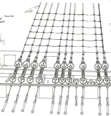
Perhaps if you think of it another way, it might help. The line you are referring to is a 'sheet' (one on each side of the sail) and is used to control the forward propulsion this sail provides to the ship. Hence, there can be a lot of force on these lines. By having two lines going through a block the force that a sailor would have to handle is cut in half. In this case one end is attached to some solid structure (a spar for example), it then goes through a block (at the corner of the sail) and the other end (the one with the arrow) is the one the sailor handles and belays to a pin or cleat. The other lines, such as number 61, are used to furl the sail. All they do is haul the sail up when no longer wanted or needed. The force to do that is relatively small. Hence no double lines are needed for that.
-
Bjoern, I know that you used the image as an example, but let me also point out that the shrouds that tie in with the deadeyes (per your picture) should line up with the top of the mast. In other words, if you connect a pencil line with all the shrouds they should come close to one point. So, don't go too closely with the drawing you saw. This is one of many published by Lennarth Petersson, 'Rigging Period Ship Models'. I am afraid that it shows the wrong angles of the shrouds to the right. If you go to the next page, it might be clearer. Pardon my personal scribbles. The plank you are referring to is called a channel. It is the board that is on the outside of the ship to which all of these 'deadeyes' and shrouds are tied to. Again refer to more ship details here or other books.
-
Looks like the way to go, Geoff. One suggestion: Try to keep the shrouds evenly spaced on top. In other words, as each shroud goes down along the mast, be sure there is an even gap between them. This becomes important when you do the rat lines. I am finding on mine that some of the shrouds are spaced a bit off and it makes the rat lines look off also.
-
I am sure the chain has been treated with some kind of polymer. Other than painting, I don't think you can 'blacken' it or give it a treatment without first removing the coating. The suppliers of modeling supplies is also an excellent source for chain in a variety of sizes and shapes.
-
Seizing or whipping a line. Here is how I have done it.
Modeler12 replied to Modeler12's topic in Masting, rigging and sails
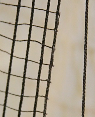
Actually there is a bit of residue, but I try to use as little glue as possible. When I made the coils for the belaying pins I used a tiny drop of PVA or carpenters glue. I used to thin that with water, but not any longer. For the whipping thread I use also a tiny drop of CA that has a bit of filler (to make it 'cap filling'). I know I should not do that, but I squeeze the excess glue away with my bare fingers and then wash my hands shortly there after. Never had a problem, unless I held it too long with the CA. I keep a bottle of my wife's 'nail polish remover' handy. It is a washed down version of acetone and as long as it is ok for women, it is ok for me. Below are two pictures. One is the top of the gaff (spanker sail) and it shows not only a small kink in the line but the darker tone because of the adhesive. The second one is part of the ratlines. Here I used a needle and thread (rather than knotting) and again you can see traces of excess adhesive.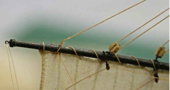
-
Seizing or whipping a line. Here is how I have done it.
Modeler12 replied to Modeler12's topic in Masting, rigging and sails
Hi Bob, I made one little 'hick-up' in the video. The loose end of the whipping thread should go through the loop after the seven or eight wraps. I jumped the gun in my narration and said to 'loosen the thread that is taped to the hemostat . . .'. I did not change that and I hope it did not confuse you. -
Seizing or whipping a line. Here is how I have done it.
Modeler12 replied to Modeler12's topic in Masting, rigging and sails
I should have explained that when I referred to 'large' versus 'small' blocks, I was referring to the length of the block or more clearly the size sheave or wheel that is inside. Blocks with the same size sheave can be wider when they are double or triple blocks, and as Henry pointed out, when they become special configurations with two sheaves mounted above each other in the same block (a fiddle). However, I have never seen a setup where a line runs through blocks of two different sheave sizes. A thin line in a large block could easily snag between the sheave and block wall. -
Seizing or whipping a line. Here is how I have done it.
Modeler12 replied to Modeler12's topic in Masting, rigging and sails
Thank you, Cor, for that comment. Inderdaad, I believe when you combine a large block with a smaller one, it would still be called a 'tackle' (at least in the case you refer to), but you have to be careful, because most of the time you would not combine different size blocks in one rigging. The block size depends a lot on the size line used. In the video I happen to use blocks that were way too large, but only to make it clearer what I was doing. Have you ever been to Lelystad and seen the replica of the Batavia? Het is een van de replicatie schepen die ik nog niet gezien heb, maar ik heb wel het boek gelezen. -
Where Do You Keep Your Working Plans
Modeler12 replied to BubbleHead's topic in Modeling tools and Workshop Equipment
I like this idea for several reasons. Plans are usually quite large and many. Having them on the computer means you can always make copies of close-ups or full size. Scaling becomes a problem, but that can be overcome. I have been shuffling eight large drawings for more than two years and they show the wear. Where do I store them? On top of the hood (or bonnet, if you please) of my 300ZX parked next to my workbench. Just have a peek at the first clip of the following video.