Modeler12
-
Posts
1,716 -
Joined
-
Last visited
Content Type
Profiles
Forums
Gallery
Events
Everything posted by Modeler12
-
 The USS Constitution has a 36 foot pinnace stowed on the main hatch cover. That must have weight a lot. How were boats like that launched? Does anyone have a drawing of the rigging involved? I am sure the capstan would be used, but what about the overhead rigging and the way it was swung over the railing? Did the spars get involved?
 -
cable laid vs rope (left vs right twist)
Modeler12 replied to davec's topic in Masting, rigging and sails
Dave, I have used the same cotton thread for most of my rigging. But I also have made 'rope' up to .040 inch thickness going the 'wrong' direction (it is S not Z). It takes close scrutiny to see the difference at scale level, so I went ahead and used it for the big stays and shrouds. Another possibility is to use polyester sewing thread and make rope out of that and then the cable. I have made rope with some that was only 0.008 inch diameter to start with. -
You have come along quite a ways since the last time we 'met'. Nice going Jim. Rigging is fun but can be confusing too. Keep it up and I know you can learn a lot from all these experts on this forum.
-
I just ran into a similar problem when rigging braces that were supposed to go to the pinrails along the bulwarks. They just did not clear the tops!!!! And I can see that a bumpkin going outwards would do that. Of course, there are other solutions, but again, I would not be surprised if somewhere, some one suggested a 'hinged or swinging bumbkin'. Is it that important?
-
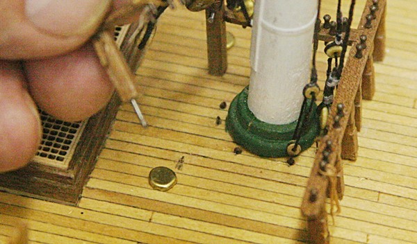
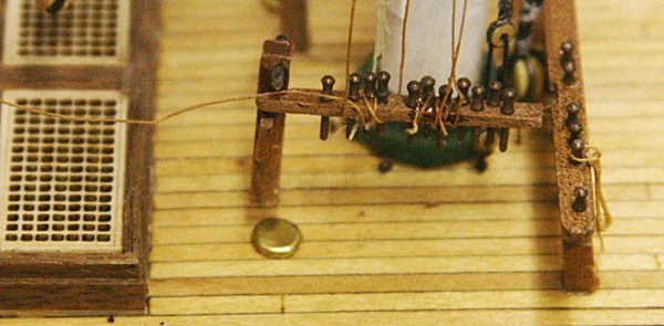
That might be tricky to line up. I think with a pin as shown below (which is inserted into the post about 1/4 inch and bonded in place with epoxy) and a hole in the deck (pencil mark) with more epoxy when I am ready to bond the whole kittagaboodle in place, I should be ok. It surely will be stronger than just edge gluing the post on deck.
-
A word of caution about mounting the riding bits to the deck. These are the posts that hold up the fife rails around the masts. As you can see I broke one off when belaying the brace lines. It was simply glued to the deck and a little tension broke it loose. With more lines to add, including the heavy ones for the main jacks, I may end up with the same problem later. I would suggest making the posts longer and having square holes in the deck into which I would epoxy the posts. I am not going to redo all of that now, but will add a pin in the end of the post that broke loose and use that to remount the post. I will also use some more epoxy in the joint of the fife rail after I clean this up.
-
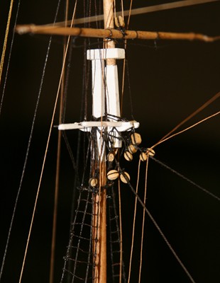
Thank you Tex. Every time I add another line and a few more blocks things get interesting. And I haven't even added the sails yet Yes all those blocks have a purpose but most are for the mizzen topsail with its clewlines, buntlines, etc. Four of them are for the braces that I am now putting on.
-
Steve, thanks for the 'invite' but not this year. That whole story of the Batavia (including the execution of some of those who were found guilty afterwards) was horrific. I have time for a few more additions to Conny and then I have to start packing for our Sunday departure. Right now the weather is not to good in western Europe and if it is raining when we want to do the Lelystad excursion we may have to cancel that. We'll go to the new Rijksmuseum in Amsterdam.
-
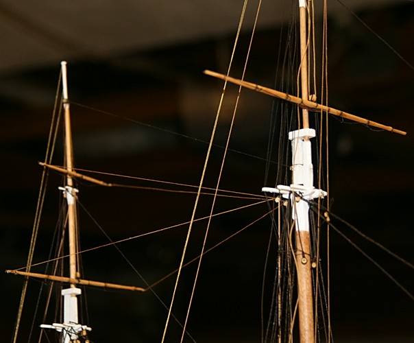
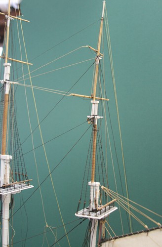
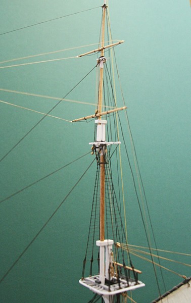
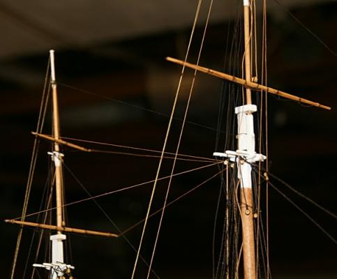
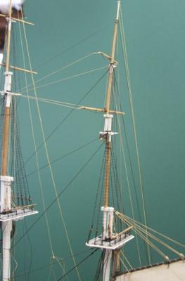
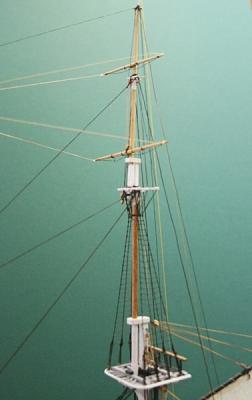
The braces may seem easy and not important at first. But they are the lines that control the fore and aft turning of the spars. The main topgallant spar has not yet received the braces in the picture below. It was not until I started to add a couple of these that I realized that they require more blocks and tie- downs at deck level. More blocks and strops, you guys! I encountered one problem with the royal braces for the foremast. According to the plans those lines would go to the pinrails along the sides. However, when I tried to do that they interfered with the top. Besides the other braces were tied off at the base of the mast. So, I decided to do the same and find a place that would not be used for any lines that I have in mind.

- 732 replies
-
- 1
-

-
- constitution
- model shipways
- (and 1 more)
-
Dave, rather than me telling you the story, you might have a look at Wikipedia http://en.wikipedia.org/wiki/Batavia_(ship)
-
Dan, I hate to be the eternal pessimist, but if you are going to spend up to $60 for a tumbler (which you might use 'sparingly') would that not buy a lot of 'good blocks'?
-
Pulley sheaves out of plastic hangers
Modeler12 replied to Walter Biles's topic in Masting, rigging and sails
Walt I like your idea. It just shows again that all it takes is a little 'insight' and that is part of the fun. Sorry Wefalck, but this time 'other plastics' etc don't do as well as ingenuity. If this works for you Walt, make me some, OK? -
Will do David and Dave. Do you, by chance, know the ill fated story of the Batavia? I read the book which, although fictional, was based on her voyage and the mutiny/cannibal acts that followed. Shortly after I read the book they found the wreckage and I understand that it is on display somewhere in Australia.
-
Thanks Geoff. We had planned to do this trip two years ago and then I tore my Achilles tendon and had to cancel. This time it should be a go.
-
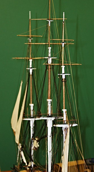
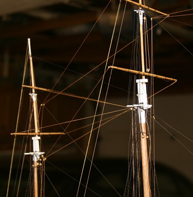
My build has slowed down but I have made a little progress with the rigging. As before, I continue to work the lines from top on down and stern forwards. I have added the bare spars on top, rigged the halyards and even added the braces. Someone ones told me to hold off with the braces for last, but I am finding that to add them where they don't interfere with other things, makes it a lot easier to belay them around the masts. The back stays and halyards go to the channel or pinrails along the outside, but as long as I am finished with other details (such as the rigging of the spanker) I went ahead and attached them. My wife and I are going to Europe for about three weeks so there will be further slow downs. We will be on a river cruise from Amsterdam to Budapest, but I am planning to go to Lelystad in Holland to visit the replica of the Batavia, a Dutch ship that ran aground west of Australia on it maiden voyage to Indonesia. The history alone is fascinating.
- 732 replies
-
- 1
-
-
- constitution
- model shipways
- (and 1 more)
-
Prachtig Anja. But are there really two different ways you did the port and starboard? I can see the difference, but only you will remember when she is finished, right?
-
That's exactly how it happened with me and it is the first finger, the one that is now more pointy. Tried to grab a small piece of wood while it kicked back and again the saw won the battle. It cut a nice kerf down the middle and now I have eleven finger nails.
-
Mark you are so right about 'it was a dumb thing to do'. I have had my share while wood working for several years. Hope you are getting along with a few scars.

-
barrel sizes
Modeler12 replied to chrish67's topic in Discussion for a Ship's Deck Furniture, Guns, boats and other Fittings
I am sorry but I had to verify if those dimensions I came up with were close. So if we look at the dimensions of the 'barrel' at 34 inch high and 22 inch diameter, we can come up with a close calculation of the volume. I took an average diameter of 19 inches and then subtracted the thickness of the staves, top and bottom to come up with 33 inch high by 18 inch diameter. The volume is then: Volume = 33 x π x 9 x 9 = 84000 cubic inches = 4.86 cu feet = 36 gallons. Pretty close to what I came up with. As mentioned I still think the ratio of height to diameter is a bit too high. I wanted shorter/fatter barrels. When I took a look at typical barrel pictures on the web I came up with a ratio of 1.3 to 1.4 instead of the 1.5 that was used above. So I will recalculate the sizes on the basis of a ration of 1.3. -
barrel sizes
Modeler12 replied to chrish67's topic in Discussion for a Ship's Deck Furniture, Guns, boats and other Fittings
Using the above dimensions I made my first crack at making them. Not perfect but these will be deep down under. This is for you Mark: From left to right we have a leager, a tun, a butt, a hogshead, a barrel and an 'I-don't-know-what'. Scale 1:64. Personally I think they are too tall (or small in diameter), but they were based on a very tall leager. For the next series I think I will modify the dimensions a bit to make them look more like a 'wine barrel', something we are more familiar with???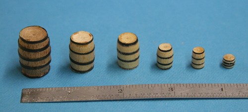
-
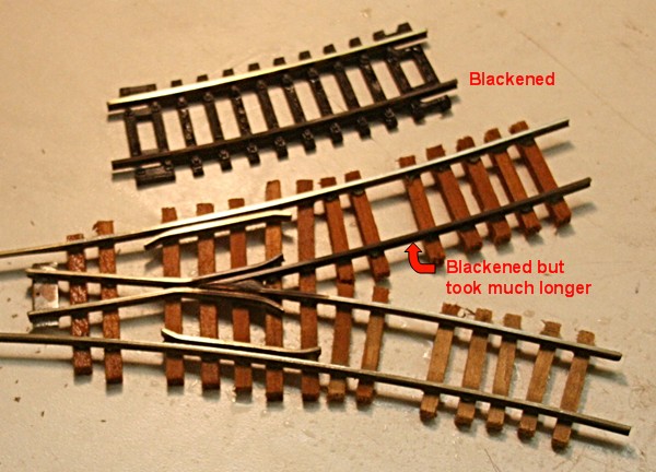
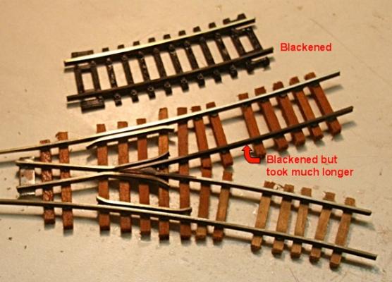
No problem, Dave and no apology is necessary, please. You were right and I was in error by simply saying that bronze is somewhere between copper and brass. Since you are an expert on metals, can you tell me if the spool of wire I showed above could be bronze? Is there a simple test for that. I suspected that it was not brass because it is too orangy in color. I tested it with the selenium acid solution and it worked fine. Probably because of the copper content. I also was interested in your comment about the nickel in model railroad track. I was curious about the difference and pulled out a couple pieces of track that have been in my attic for a couple decades. One small piece was from the old brass track and the other from the nickel alloyed material. The brass was badly oxidized and the other had a greyish cast. I sanded part of the track and coated one section with the selenium 'patina'. The brass turned black very quickly but the other one took a long time to finally show the black oxide coating. So, I am not so sure that a little nickel in these materials will prevent the blackening. Although stainless steel tongs (which also contain nickel if I am not mistaken) will not be affected. Low carbon steel will blacken. Figure that one out, Dave.
-
Well, I beg your pardon guys if I over simplified. But like I said there are many non technical members on this forum and some may not realize that brass and bronze are not the same thing. For our purposes of modeling ships, bronze is not used very often, but it just so happened that I came across some bronze wire. I just did not want to go into all those details that a metallurgist would drool over.
-
barrel sizes
Modeler12 replied to chrish67's topic in Discussion for a Ship's Deck Furniture, Guns, boats and other Fittings
I took this a step further because I wanted to know the dimensions of these various containers. The information provided by Long9Ron is the basis. His tabulated values are for volume in gallons. He also mentioned that a leager was typically 150 gallons with a height of 54 inches and a diameter of 36 inches. Now you cannot simply scale the dimensions linearly. Using volumes you have to use the cubes. Pardon the following, but it is the way I did the scaling: The height of a 'barrel', for example is the cube root of (54 raised to the third power times 150/36). This gives a height for the barrel of 34 inches and a diameter of 22 inches. Here are the values for the others: Leager 150 gallons 54" high x 36" diameter Tun 220 gallons 61" high x 41" diameter Butt 110 gallons 49" high x 32" diameter Hogshead 54 gallons 38" high x 25" diameter Barrel 36 gallons 34" high x 22" diameter Rundlet 16 gallons 25" high x 17" diameter These are rounded of and not very accurate, but since there were no real 'standards' they are good enough for me. You might want to compare this with the picture Ron showed for various containers. Now I can make my own 'barrels'. BTW a barrel of rum would weigh about 300 pounds. -
what powertools to buy
Modeler12 replied to Adrieke's topic in Modeling tools and Workshop Equipment
Here is one source, Danny. http://www.ebay.com/itm/50-Piece-Solid-Carbide-Micro-Drill-Bit-Set-Jewelry-S2A-/150463241831 But there others. Google 'micro drill bits' or go to http://www.google.com/imgres?imgurl=http://www.micro-machine-shop.com/micro-drill_set_carbide.jpg&imgrefurl=http://www.micro-machine-shop.com/drill_bits_countersinks_reamers_counter_bores.htm&h=340&w=640&sz=41&tbnid=tKC3fJggksoINM:&tbnh=66&tbnw=125&prev=/search%3Fq%3Dmicro%2Bdrill%2Bbits%26tbm%3Disch%26tbo%3Du&zoom=1&q=micro+drill+bits&usg=__M74_TNhVSAgdE-KzTiJSaJ0gvR0=&docid=LbVeevs67FllrM&sa=X&ei=sBmVUe3xKqKriAKJtoGwCQ&ved=0CGkQ9QEwBQ&dur=588 -
what powertools to buy
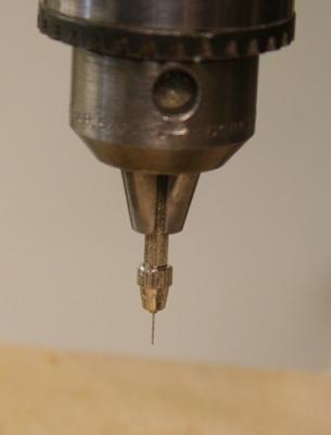
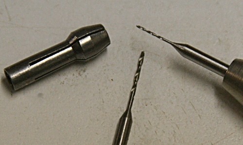
Modeler12 replied to Adrieke's topic in Modeling tools and Workshop Equipment
Danny I am glad you clarified the last part about putting a pinvise into your drill press. It is a good idea, so I tried it and sure enough the little rascal was spinning all over the place. But after some 'tuning' it did work. What I also have done is to use the collet that comes with a Dremmel kind of tool. You can insert that directly into the chuck. Another way is to buy some drills that are a lot more stable because they have a 1/8 inch shank. One source for a few is https://www.mcfeelys.com/product/PX-88/Tungsten-Vanadium-Micro-Twist-Drill-Bits But there are several others.