


Srodbro
-
Posts
291 -
Joined
-
Last visited
Content Type
Profiles
Forums
Gallery
Events
Posts posted by Srodbro
-
-
-
Oh, yeah. In my previous post that gunboat pic might be copyrighted by AP so if an administrator wants to pull it that's fine.
My point is that the true appearance of Niagara may be more like the camels in Pathagoras's model than the Brig. (Love that display, by the way).
- mtaylor and pythagoras
-
 2
2
-
Pythagoras's model of lifting the brigs over the bar might be better appreciated in the context of this pic of Gull Point at Presque Isle.
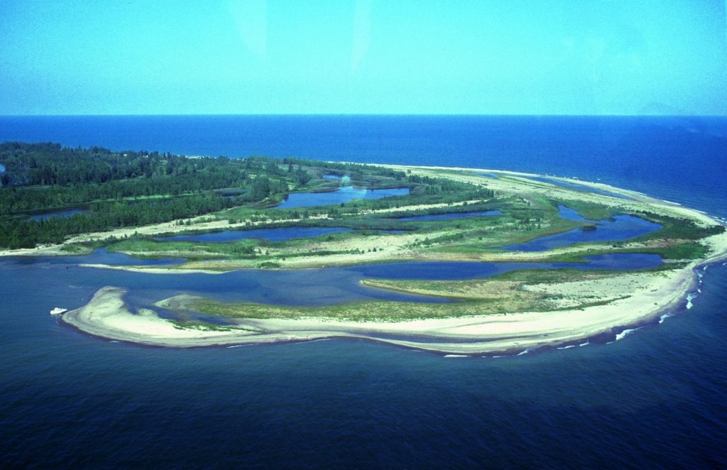
Lots of sand to deal with around there!
Now that I've started my build of Niagara and am reading a bit more about the construction of the brigs, the picture is becoming much more clear that the originals were much more "rustic" (as someone said above). Given the time constraints, lack of materials and building talent, I wonder if they were just barely afloat? Given all the constraints, I can't help believing that "shortcuts" were taken. How many trenails had to substitute for iron spikes, and how many of those were installed spaced farther apart? Was there a lot of time spent faring the hull? How much did they plane the planking to get smooth surfaces? Was there enough oakum to fully caulk...were they really wet boats? Since Lawrence was started before Niagara, did she get any preference in use of available materials? Were they short of cordage, so the rigging they might not be as weatherly as desired? If so, could that have affected Niagara's sailing abilities (and contribute to Elliot's tardy arrival to the battle)? As far as the outward appearance, I'll bet they weren't too different looking than the gunboat (also built in a hurry) in the pic below.
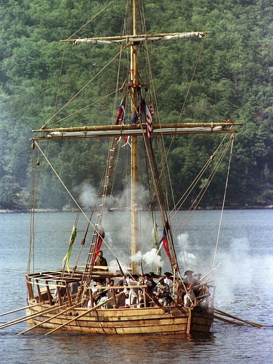
It would be interesting to build a model version of Niagara and Lawrence (as well as HMS Detroit) that focused on how deficient they may have been (compared to the "idealized" reconstructions we are familiar with). Which, IMHO, would only increase the appreciation of the battle.
-
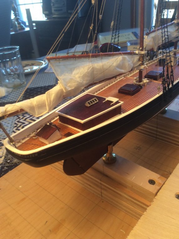
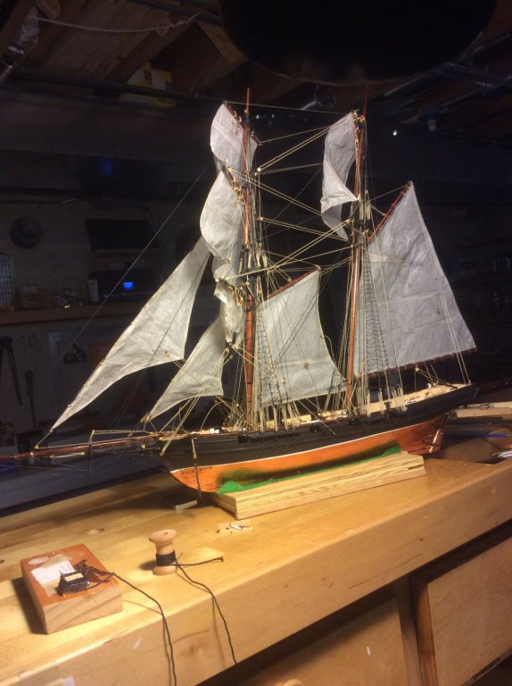
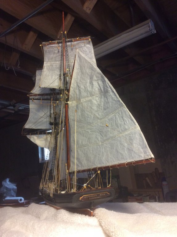
I also felt that sails on a schooner model were important. I also agree that if you have sails, you need water. Here is my We're Here. (Please forgive the temporary tape on the display case).

I found that it was essential to reduce the sail area to about 60% of actual or the volume of sail material overwhelms the model, if sails are furled. Also, I find I get better looking sails when made of tissue paper than any cloth I've found. By saturating the bolt ropes in dilute white glue and allowing to dry before furling, the sail can be draped easily.
-
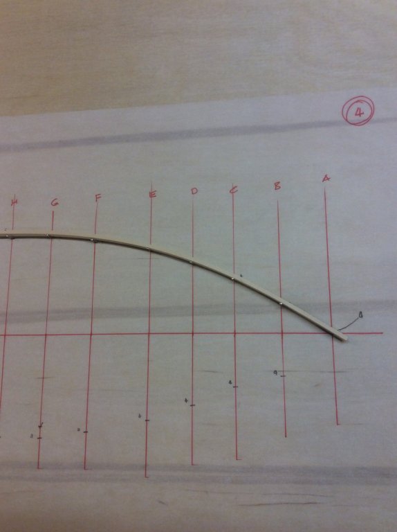
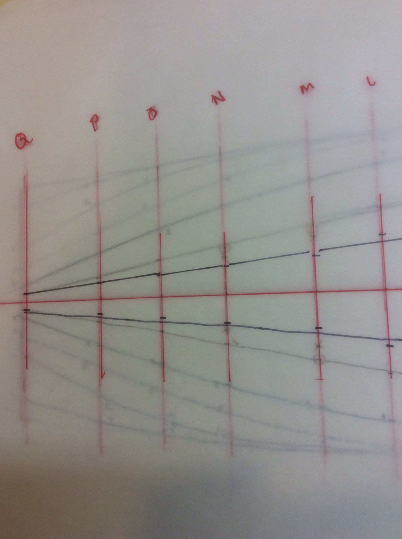
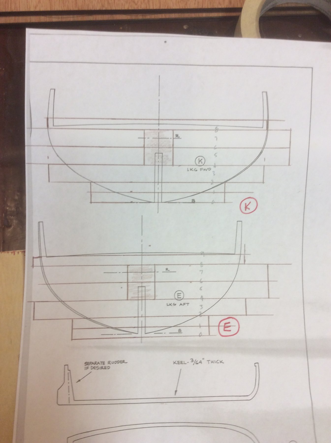
Here is a pic of the combined lift lines that I created from the kit drawings. I neglected to include anything aft of "Q" section line. (The pic is foggy in some areas because you are looking through nine layers of tracing paper. These sheets of paper I glued onto my lift blanks.
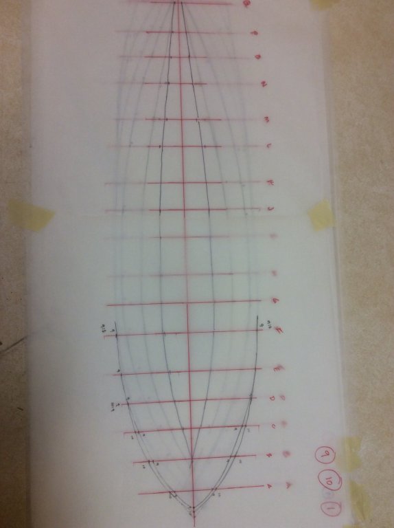
i "corrected" this omission after having glued the patterns to the lift blanks, by taking points off the drawing detail 2-H, after adjusting for my lift blank thickness.
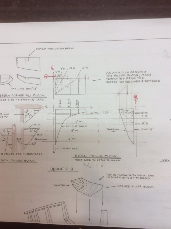
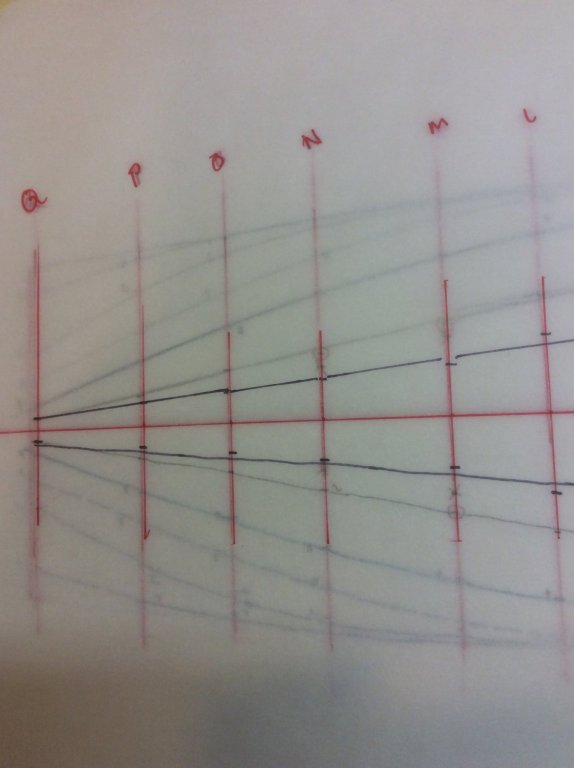
But, I didn't really have a clear picture of how the complex shape of the hull married together with the sharp angles of the stern stanchions. In retrospect, I probably should have ended my hull at "Q" section line, but I didn't, I just smoothed the curves of the upper lifts to a pleasing termination. (Call this Big Mistake #1 -- BM#1 -- I'll revisit this later).
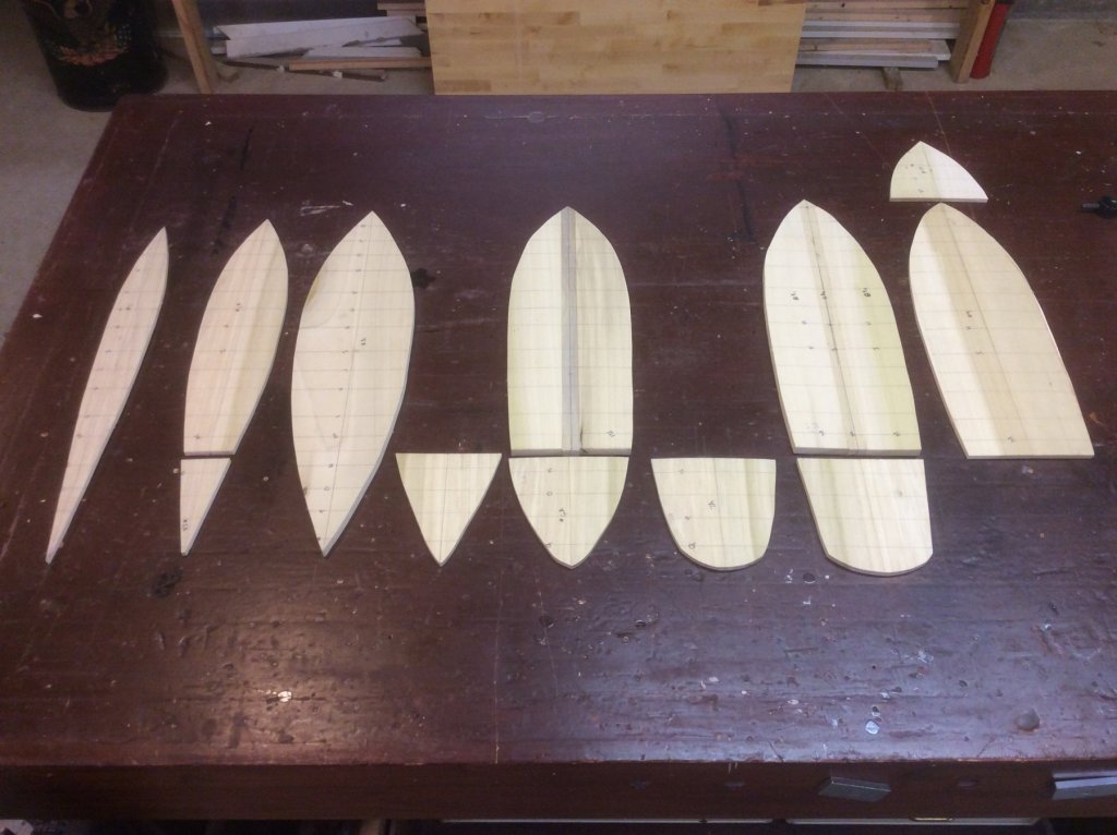
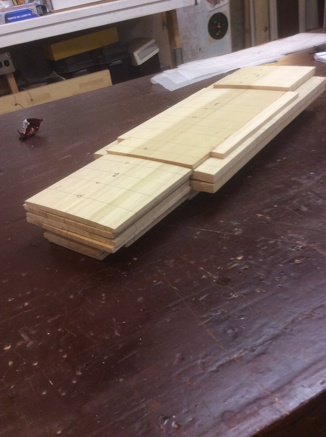
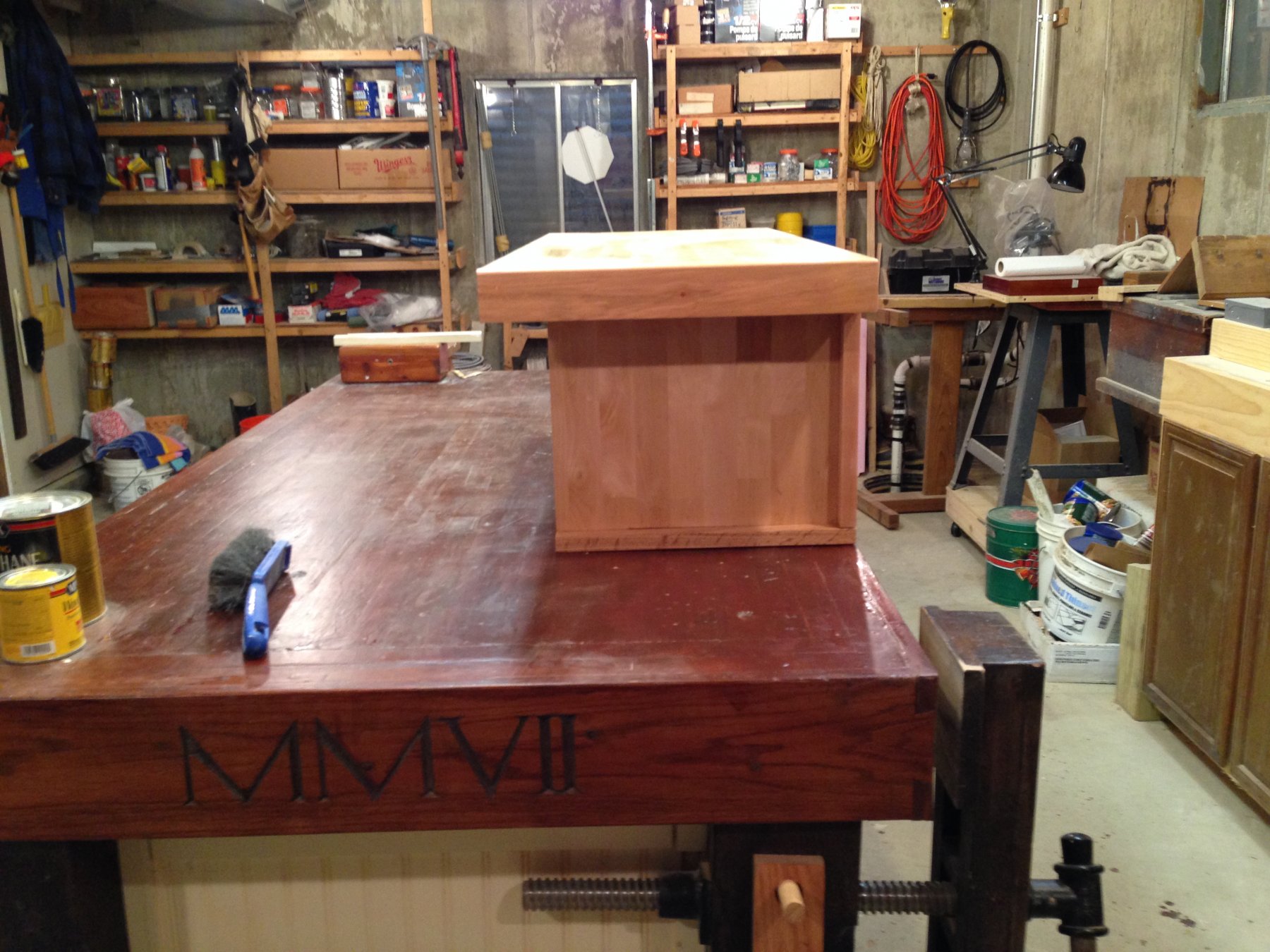
Next I assembled the raw materials of my lift blanks into the proper size.

I used poplar from the craft section of a local lumberyard, which came wrapped in plastic. The blanks were 1/4 and 1/2 (actually 7/16) inches thick. It didn't take long for these thin sheets to warp once in the humid basement shop. But, I figured (hoped) that by alternating the cupped surfaces the glue would bond them together.
There is a split between section lines "M" and "N" which divides the aft third of lift 5,6,7 and 8, which are all 1/4" thick, from the forward two-thirds, which are 1/2" thick for lift 5/6, and 1/4" for lifts 7 and 8. This was done to provide more waterline lift points where the stern shape transitions so much more than the bow. The lifts below lift 5 are the full length of the hull. (I hope this doesn't wind up being BM#2!).
After gluing on the lift patterns to each blank, they were cut out with a saber saw.
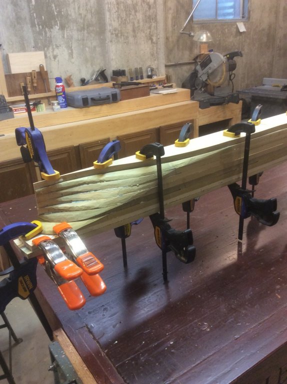
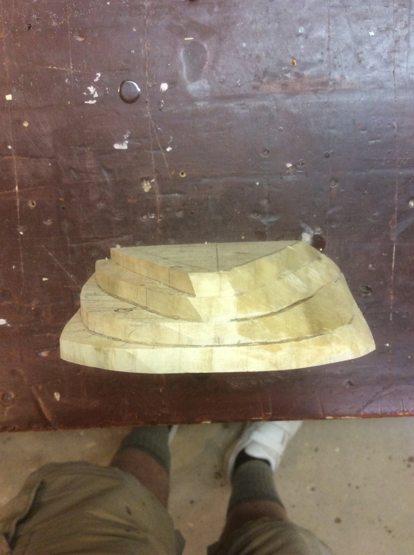
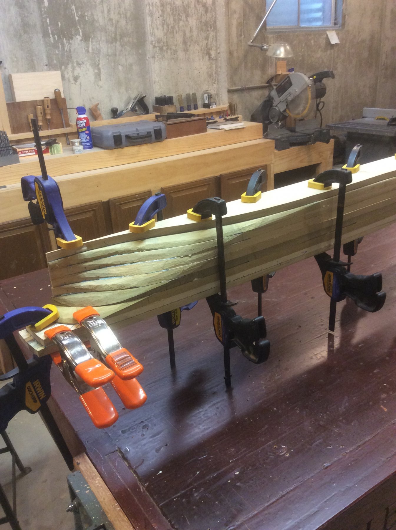
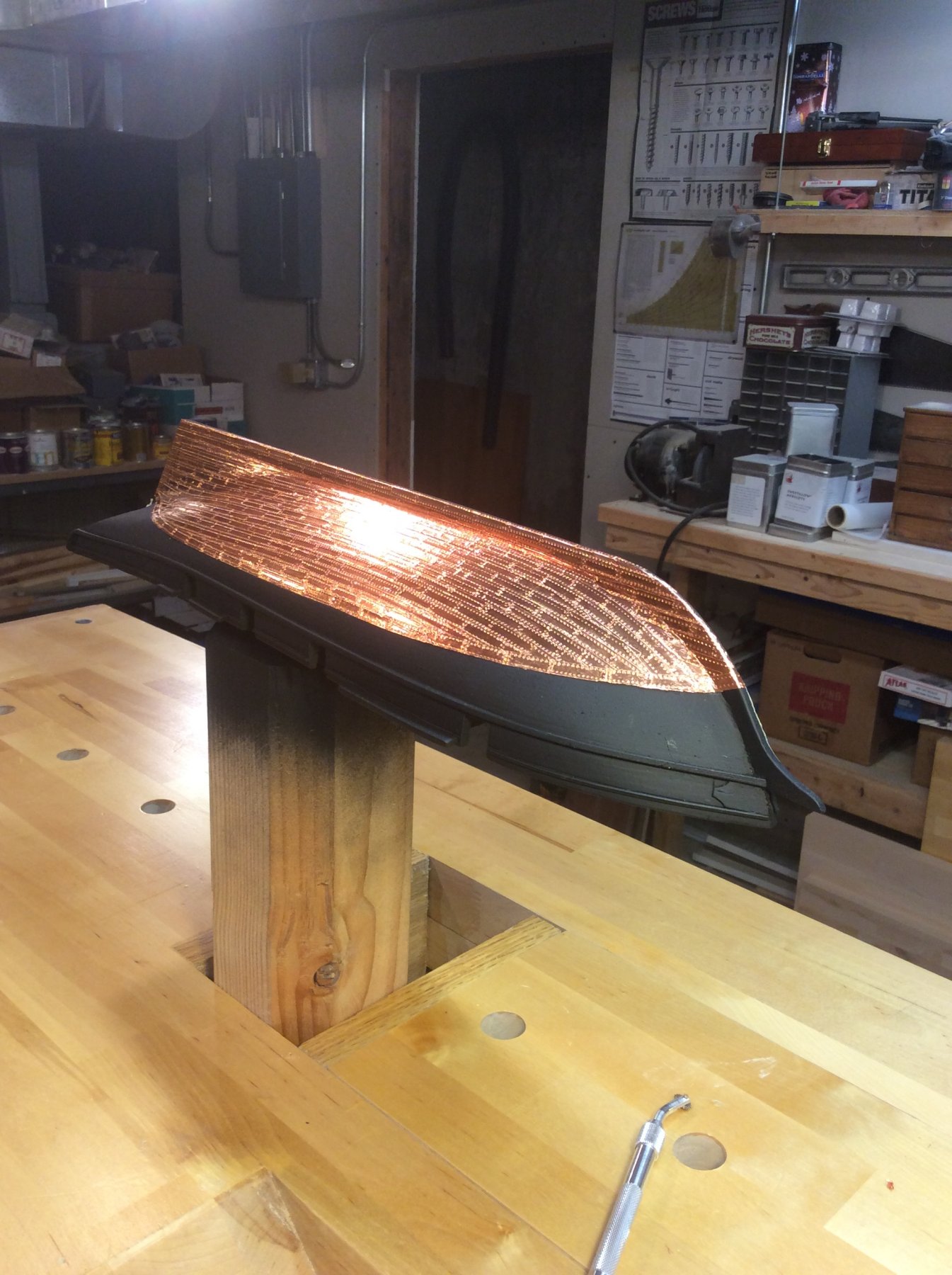
The lowest three lifts were glued together, the aft-third four lifts glued together, and the forward lifts glued together, in three separate subassemblies to facilitate initial shaping. Here is the stern subassembly with initial shaping on the right

Then the three subassemblies were glued together.

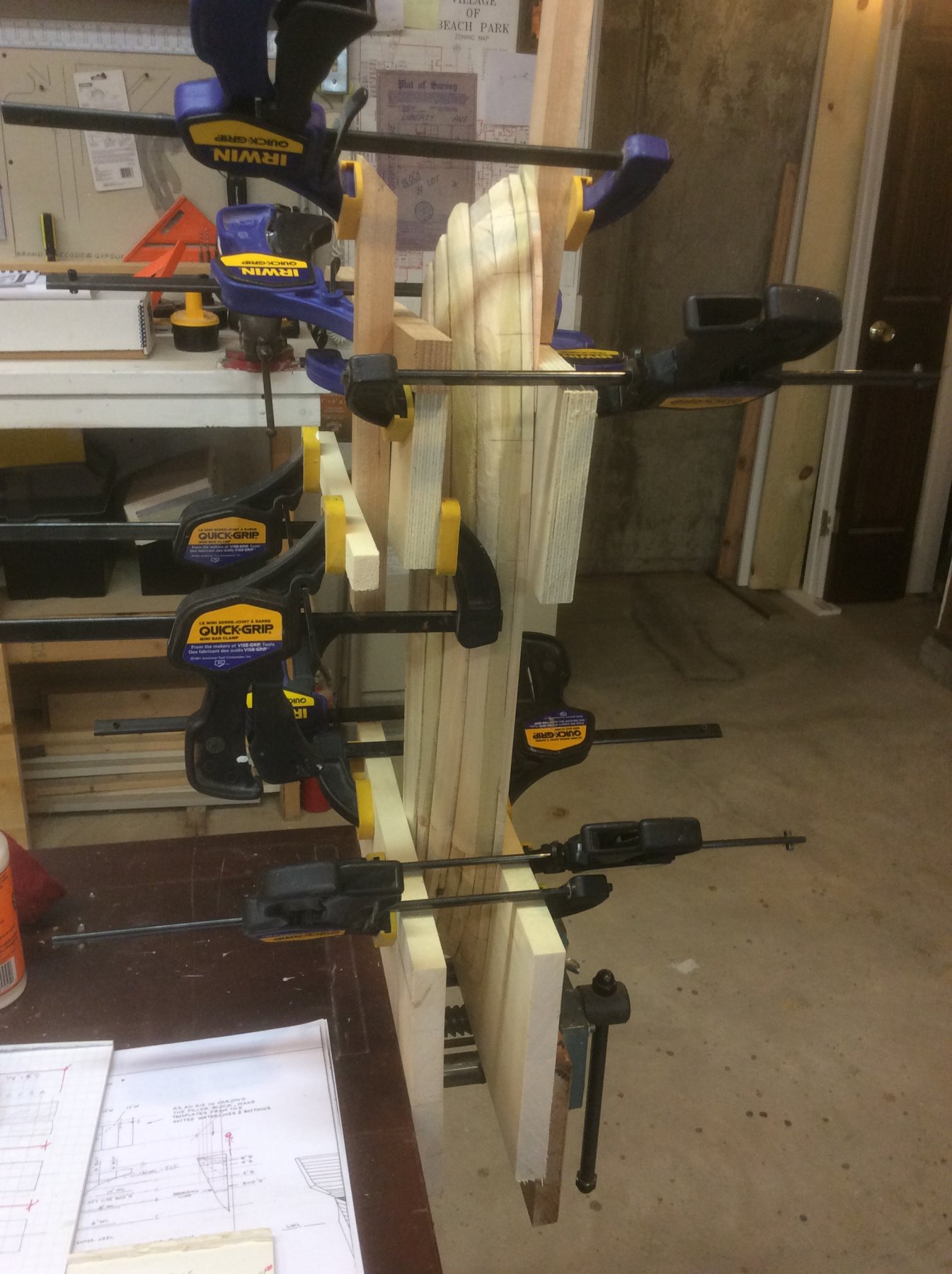
After setting up in the clamps and vice overnight, I gathered together my arsenal for shaping the hull.
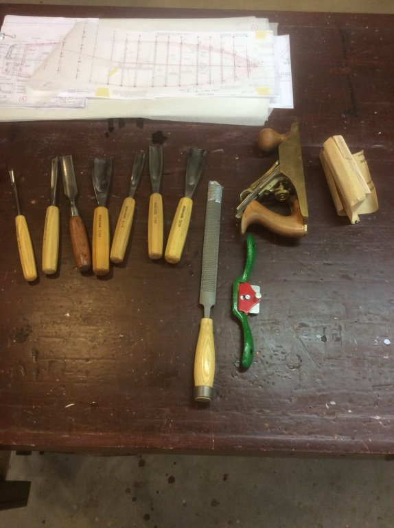
I used the Waste" from around the kit's laser cut bulkheads as templates for the shaping.
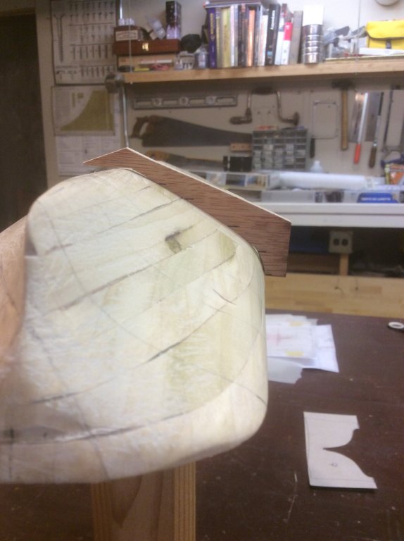
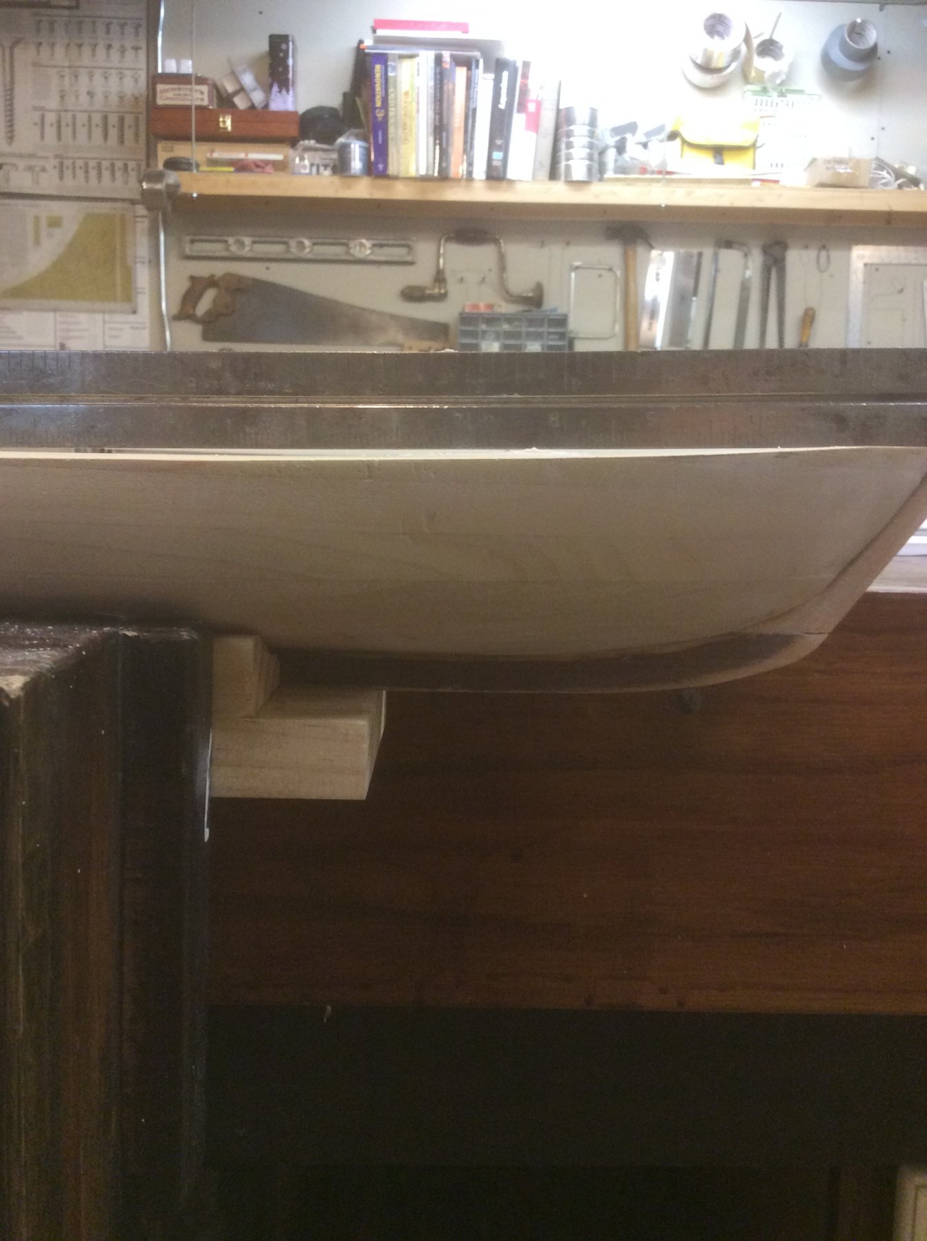
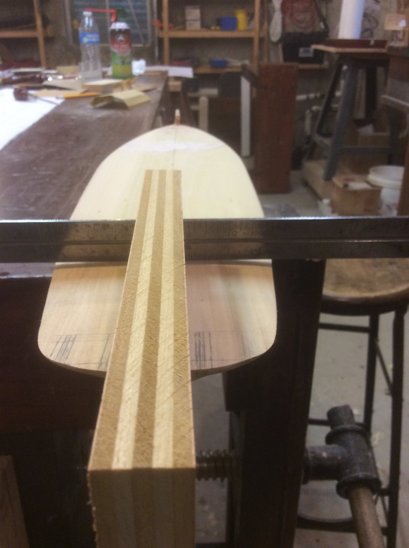
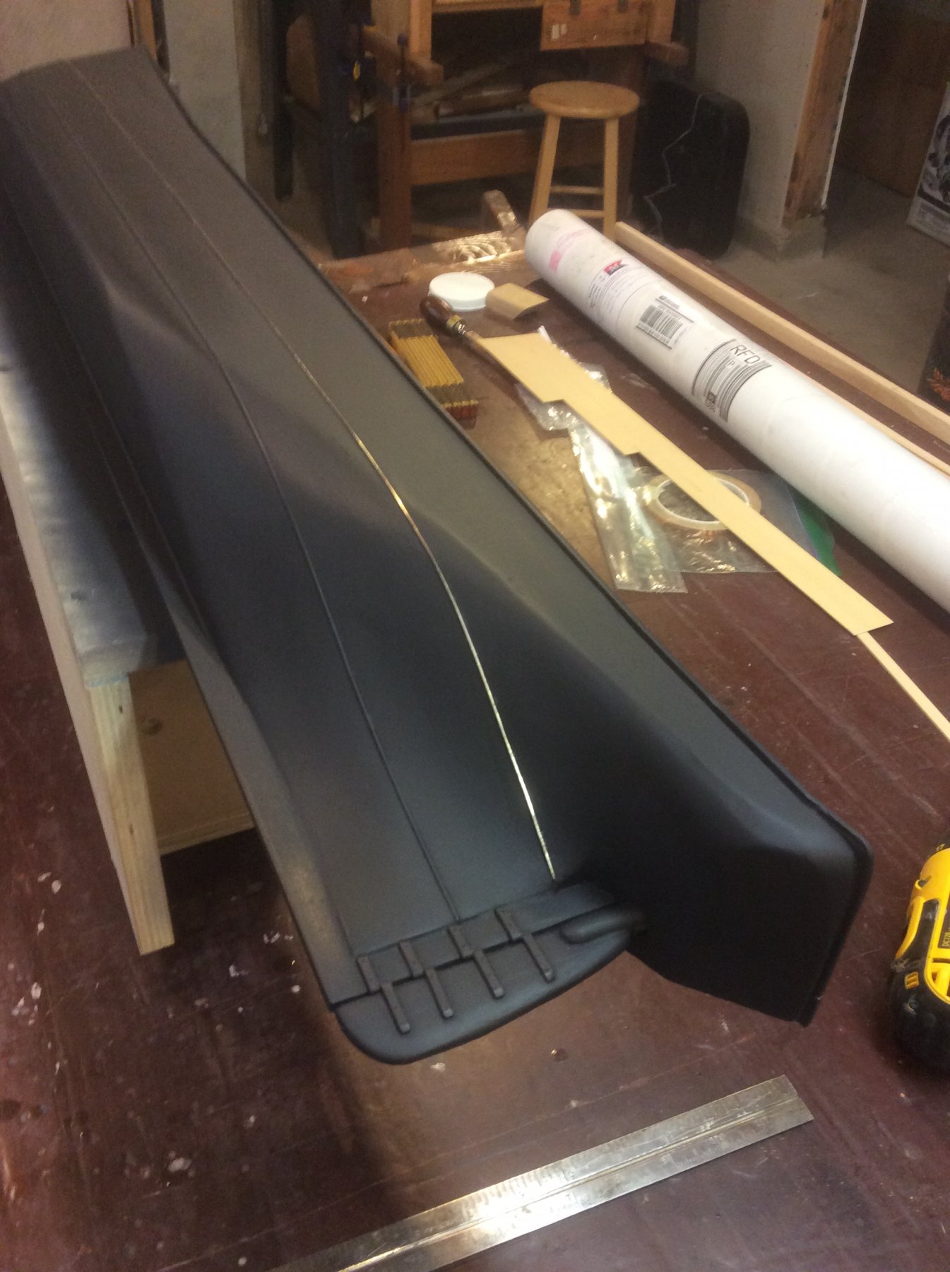
Rasping, sanding, filling, more sanding, and an acceptable hull emerged.
Then the topside needed attention. There is a slight rise to the deck from stern to bow.
And a camber to the deck from centerline to the sheer.

This pretty much completed the major shaping of the hull.
- Tigersteve, Derek C and Elijah
-
3
-
6ohiocav:
A couple factors contributed to my choice of approach. Familiarity with working on solid hulls; knowing that a solid hull can take a lot of abuse during the process; ease of securely mounting it while working on it. I also saw that most builders add varying amounts of blocking between bulkheads to reinforce the skeleton (not the least of which was illustrated by your log, of fillers between A and B bulkheads as well as everything aft of "O" bulkhead. I figured there wouldn't be too much more involved to just make it solid to begin with (which I am learning may not be entirely true) -- but, that's the heart of the experiment.
The closest the laser cut bulkheads are coming to being used in the model is that I'll be using the "waste" that surrounds them as templates to check my hull.
As following posts will show, I am constructing the hull of laminations as might be done for a half-hull model.
- Elijah and Tigersteve
-
2
-
This will be my first build log, and I wasn't sure if I should have it here, in the Kits forums, or in the Scratch build forums, since I am diverging so much from the normal, plank-on-bulkhead technique. I decided on the Kit forum, since nearly everything I'm doing is, well, based on the Model Shipways kit and drawings. All of my previous builds (Yankee Hero, Fannie Gorham, We're Here, Dapper Tom, and a recent 1/2-hull - 1/2- model of six masted schooner Wyoming) have been solid hull projects. I found dealing with my builds of New Bedford Whaleboat (PoF) and Grand Banks Dory (PoB) to be tedious due to the light weight construction. When I decided to build Niagara, I thought I'd try to construct a solid hull upon which to later apply the planking, and then complete the model per kit instructions.
I have made some some progress on this effort, and thought I'd share the experiences of this experiment. A couple of thoughts to begin.
My old microbiology professor preached "Hinkley's Law", which said "Most experiments are failures." I expect that may turn out to be true for this one, as well.
During this build I have found the build logs of 6ohiocav and mikiek very informative; the website Niagaramodel.com is invaluable.
The responses to my earlier post on planking a solid hull by BACKER and Pete Jaquith were helpful. I chose to ignor the advice in wefalck's response (sorry).
So, here we go. Hold fast!
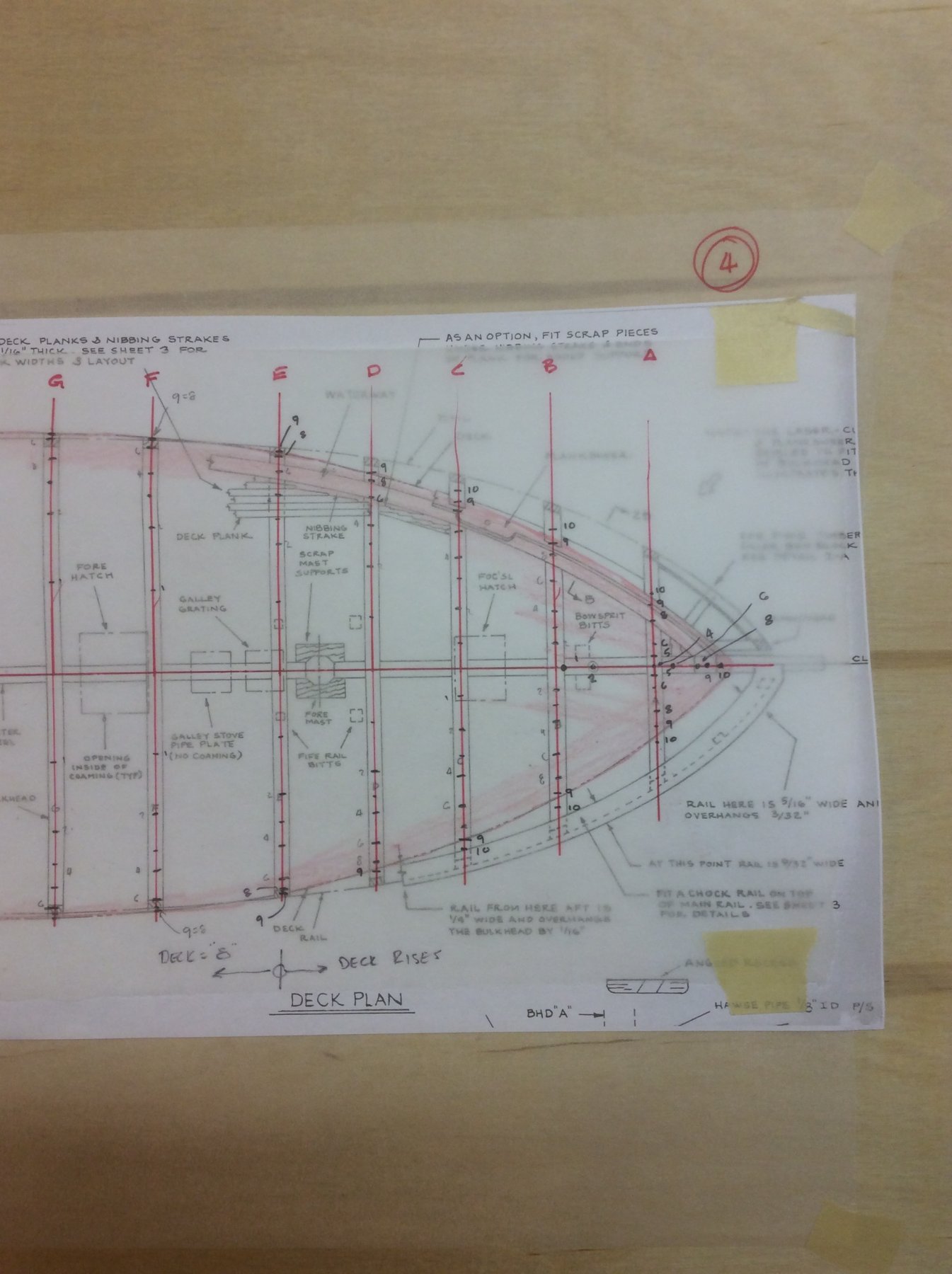
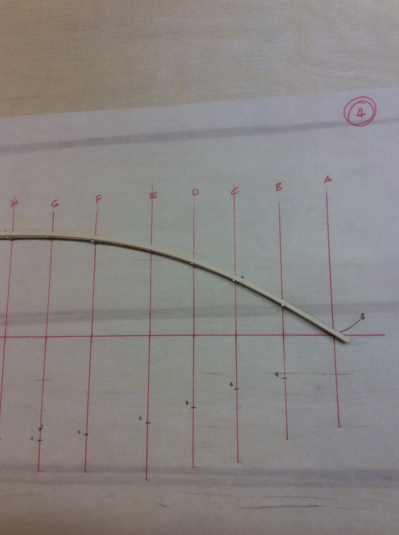
My first task was to create a set of waterline drawings from the drawings in the kit. Let me say up front that creating these was fraught with the opportunity for error. Every time a point is transferred from one drawing to another, or from paper to wood, error can occur. I calculated that given the number of sections, the number of points on each section, the number of transfers, I had a 1 in 960 chance of matching the kit drawings. At best.
I first drew onto the kit sections of the bulkheads the outline of my wood layers. From these I measured from centerline to the intersection of each layer with the section curve of the bulkhead. This distance I transferred to an overlay of the kit plan. Then, on another overlay, I connected the points for each layer by faring with a wood strip pinned to the drawing. This gave me a pattern to glue to my wood layers for cutout.
Next: attacking the wood.


- Elijah and Tigersteve
-
2
-
-
Following your build log with great interest.
I, as well, am building Niagara. But, in reviewing several build logs, became concerned with the lengths to which builders have to go to keep everything square and rigid, so decided to build a solid hull based on the kit drawings and templates.
I had to construct my own waterline plans since the kit plans didn't include them. I fared the points taken from the kit section drawings and plotted onto a plan using pins at each point and a strip of wood.
I found several points, on section line "M" and "N", about midway between the keel and deck, where the hull shape transitions from convex to concave, that could not possibly be "fare".
I noticed that your pic shows shimming at section "F". I was wondering if you tested the "M" and "N" area with a batten , and if so, have you found the need to shim at this location.
-
Thanks to all for your tips.
I have decided to go ahead and build-up a solid hull, having lifted water lines from the kit drawings.
Should this approach fail, I still have all the kit components, to which I can add fillers from the failed solid hull (if that comes to pass), and then proceed per kit directions.
Thanks again.
-
I wound up using poplar obtained at a local woodcraft shop, primarily because it was readily available, dry, square, and the thickness (1/2") was same as the waterline spacing on the drawings. It works quite well with hand tools. I think it turned out OK. I think because of the many layers in the glue-up it will be pretty stable. When I mounted it on the oak backboard, I secured with wood screws, but used slotted holes to allow for any differential expansion between the model and backboard.

- Roger Pellett, John Allen, Rudolf and 6 others
-
9
-
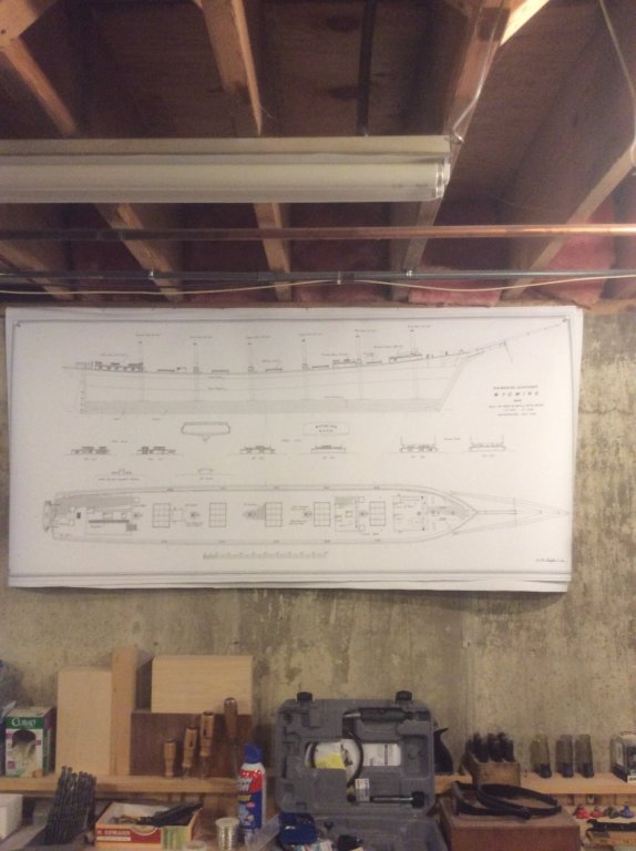
Stapled to the sill plate above the concrete basement wall, or for small plans, buried under the project materials on the bench.
- Canute, thibaultron, mtaylor and 1 other
-
4
-
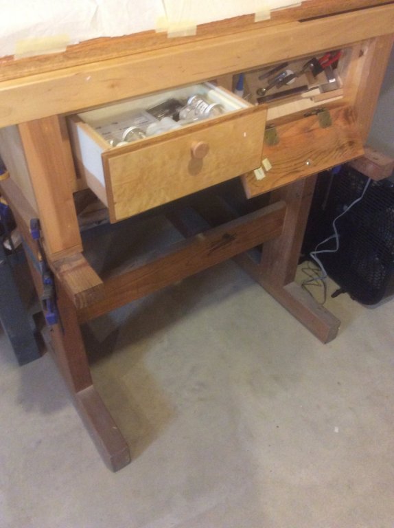
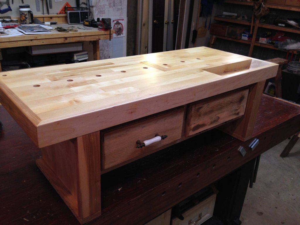
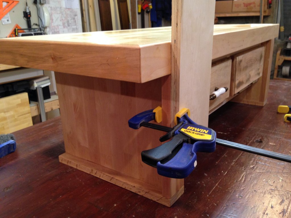
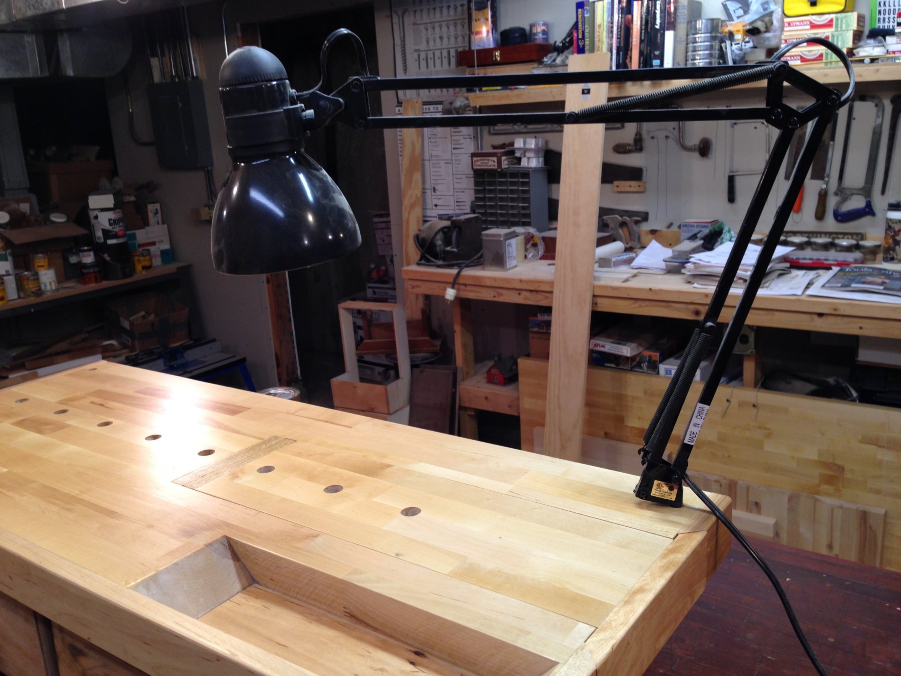
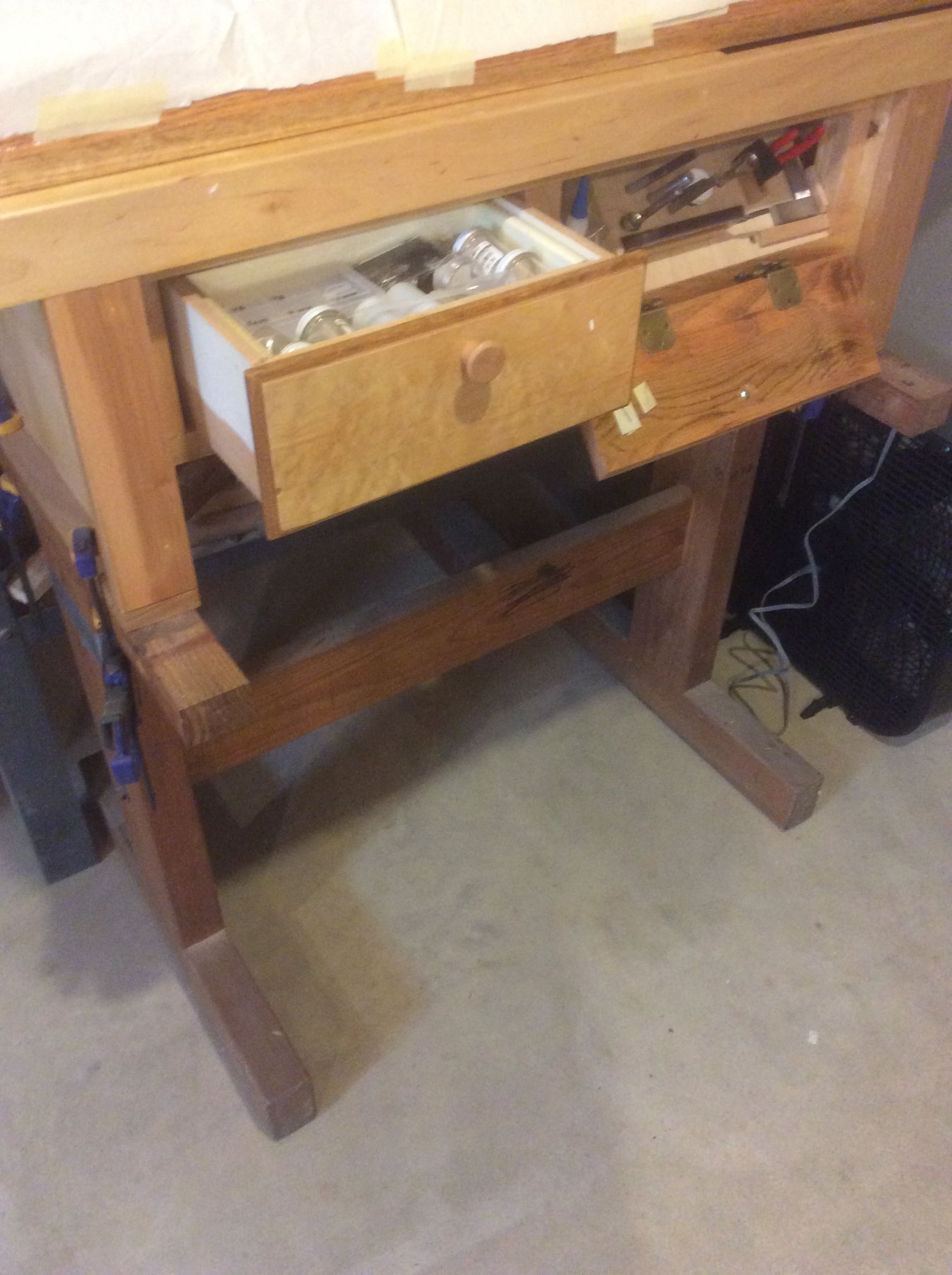
Just a basement workshop, but I did construct a mini-bench for my models. Modified from some drawings in a woodworking magazine, I have a center "tail vice" that can hold inverted hulls in about any position or used with bench dogs to hold things mounted on flat base, a depression in the top for tools/parts, drawers for frequently used tools and parts, and a mounting hole for the all important light.
But, the best feature is its portability. When not mounted on the main shop bench, it can be mounted with clamps on a pair of sawhorses, or moved to a table elsewhere. I like working standing up, and the height is just right for that, and the mini-bench facilitates resting your arms on it while doing fine work. If I decide to work seated, I move it to the sawhorses. The legs are designed with flanges to allow clamping work to them as well. Finally, when the Admiral demands work on another project, the bench with model can be moved out of harms way.


-
Thanks so much for your response and directing me to your build log. Great project -- beautiful workmanship. I look forward to following your progress.
While you have filled between bulkheads (frames), I intend to eliminate bulkheads altogether by making a solid hull. I noticed that you have used wood filler in some locations, which I anticipate I will need to do as well. I am curious as to whether you applied adhesive to any of your filler to attach the planking, and if you have any concerns about the compatibility of the filler and adhesive?
-
My next build will be the MSW Niagara. This is my first PoB kit. All previous builds have been solid hull, including my most recent, a 1:96 scratch-build half-hull of the six masted schooner Wyoming. While reading several of the build logs for Niagara and Syren, I've become concerned with all the effort required with keeping bulkheads square and properly aligned (construction of special jigs, etc.) proper beveling of the edges, removing laser charring, and then learning that, in addition to having to carve the bow and counter, many builders find they need to add solid fillers between the bulkheads to keep things rigid. So, I am considering just building a solid hull to begin with, then planking it.
In searching the forums and the Sultana practicum, it is clear that planking solid hulls is not unusual (and frequently done in Europe). Seems straightforward: Just follow the same planking methodology as PoB or PoF, knowing there are a lot more points at which one could apply glue and insert temporary pins. As a bonus, the "waste" around the laser-cut bulkheads in the kit will provide nice templates for shaping the hull. Aside from the need to develop my own lift lines from the kit sections, and forever dealing with a heavier hull, I can't think of any major obstacles.
My question is: Does anyone know of any special considerations for planking a solid hull?
-
In the original post, in the second and third pics, the instructions on the left are the older set. The copyright date of the older set - 1966 - can be seen under the "Standing Rigging" title. The copyright date 1976 can be seen on the newer set in the lower left corner of the "Lifts" diagram.
In the pic of the belaying pin diagrams, the lower Plan is the older (I have them from the kit I purchased in 1968) and the copyright date 1976 is visible in the upper Plan.
So ... the rigging plans got better, but the belaying plans got worse?
-
Captain Al's pic of the American Eagle shows several lines wrapped around the gaff and boom, holding the sail in place when the gaff is lowered. If those are utilized, then, as Russ points out, the peak and throats halyards can be pulled taught as if under strain from the weight of the gaff.
Worked ok on my schooner model.
-
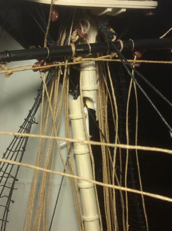
As stated by wefalck in his reply above, overly tight standing rigging can do a job on a mast (see the pic). In this case, I had returned to my model of Connie that I started 50 years ago, to finish rigging her. A styrene mast that sat in the attic for decades found a way to slightly warp, and I thought I could straighten it out with tight rigging. I was successful up until about a week after I completed the model, when there was an audible "ping" in my study, and an odd cant to the mizzenmast.
- thibaultron and mtaylor
-
2
-
S. Coleman:
i, too, favor limiting my knot tying on ratlines and use of 50/50 to secure them to shrouds. I am curious as to how the ratlines were held in place while you glued to the shrouds.
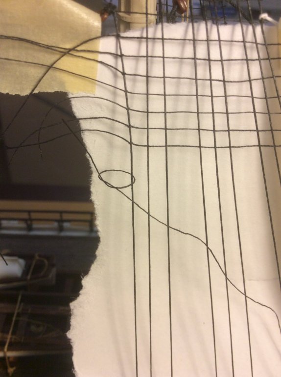
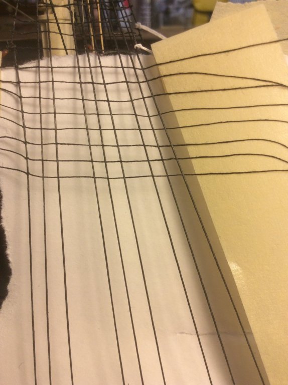
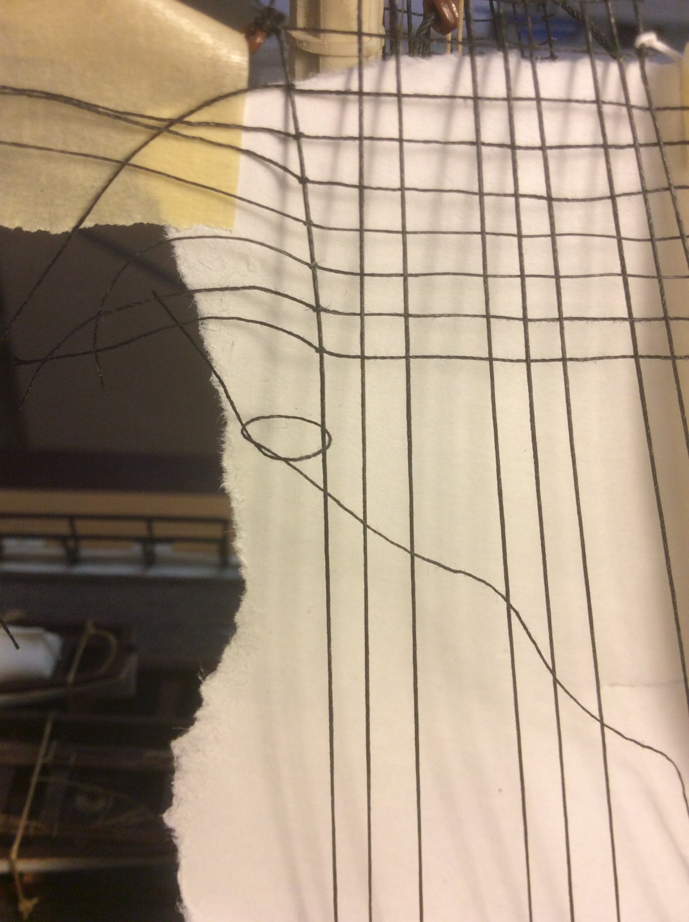
Here is my method, as shown in the pics:
1. Secure a piece of paper behind the shrouds. This to better be able to see what I'm doing, and to separate the ratlines rigging process from the rigging in place behind the shrouds.
2. Secure a strip of masking tape along side of and parallel to the outermost right hand shroud.
3. Use a simple overhand knot to secure the ratlines to the outermost left hand shroud.
4. "Weave" the ratlines, in-and-out across the shrouds. Very gently lay the tail of the ratlines across the strip of tape. Repeat the process for several other ratlines, alternating the passes over the shrouds. Note that there is still some "hourglassing" of the shroud that the ratlines was tied to, but that can be eliminated by lifting the ratlines off the tape and adjusting to the final location before applying glue mixture. After glue dries, trim the ratlines ends.
5. Since I took the pics I've learned to begin the process about midway between the lanyards and the top, and to install only about five ratlines, adjust, then glue into place. This makes the effort to eliminate the "hourglassing" much less, and, after the glue dries on the initial five lines, helps prevent it on installation of the next ratlines above and below.
I have found this works well on lower masts, where there are more than, say, four shrouds, but it doesn't work well if there are four or less, as the tension on the shrouds in the "basket weave" is most responsible for holding the ratlines in place until glued.
Hence my question on how you hold the ratlines in place until glued.

-
-
I built Dapper Tom as my fourth solid hull model (Eastport Pinky, Fannie Gorham, We're Here). All previous kits were Blue Jacket. The last kit hull blank was so bad (the bow-stern centerline at the deck was skewed out of line with the keel centerline so badly that you could never match the lines on the plans) that I swore off solid hull kits. But then I purchased on eBay a vintage (1950's or early 60's) partly finished kit of Dapper Tom. The hull was pine, and the shape matched the templates very closely; hats off to that unknown modeler. The instructions in the old kit were on one sheet of paper so I bought the Modelexpo plans and downloaded the instructions.
I have enjoyed this model so much I've bought the newest modelexpo Dapper Tom kit.
Here's the thing: except for the extreme sections at bow and stern, the rough hull blank in this new kit is close enough that light sanding will make it acceptable. Now, nobody is going to see my model in a museum, so the lines just need to be pleasing enough for the case in my study.
Here are pics of the near completed kit. I chose to put sails on her. Also, since she really never existed, I chose to rename her Quoddy Bay in homage to the privateers that sailed out of Eastport around 1813.
- usedtosail, mtaylor, etubino and 2 others
-
5
-
Suggest White-Jacket: Life on a Man-of-war, by Hernam Melville for 19th Century American Navy life on a frigate.
Also, there is an unforgettable chapter in Victor Hugo's novel Ninety-Three, about the battle with the canon (from whence "loose canon" derives) Amazon has a $2 kindle edition version, with period illustrations.
For us oldsters, suggest Joseph Conrad's Youth. A good short read on a winter eve with a glass of port.
-
-
I have the plans for the six-masted schooner Wyoming, and would like to build a half-hull model of her at 1/8"=1' scale. This will be quite large (about 43" long x 3" thick x 3 3/4" tall). I've made several solid hull kits, most of basswood, one of some sort of pine, which have turned out well, but the largest hull was only about 18" long. I have read the Half Model tutorial, and several of the forums, and am seeking advice on the proper wood (poplar seems popular) to use. I plan to paint the hull, so staining is not a consideration.
Any suggestions? Any concerns about warping or twisting of such a long, narrow piece?
Thanks.


US Brig Niagara by Srodbro - Model Shipways - Scale 1:64 - Solid Hull Experiment
in - Kit build logs for subjects built from 1801 - 1850
Posted
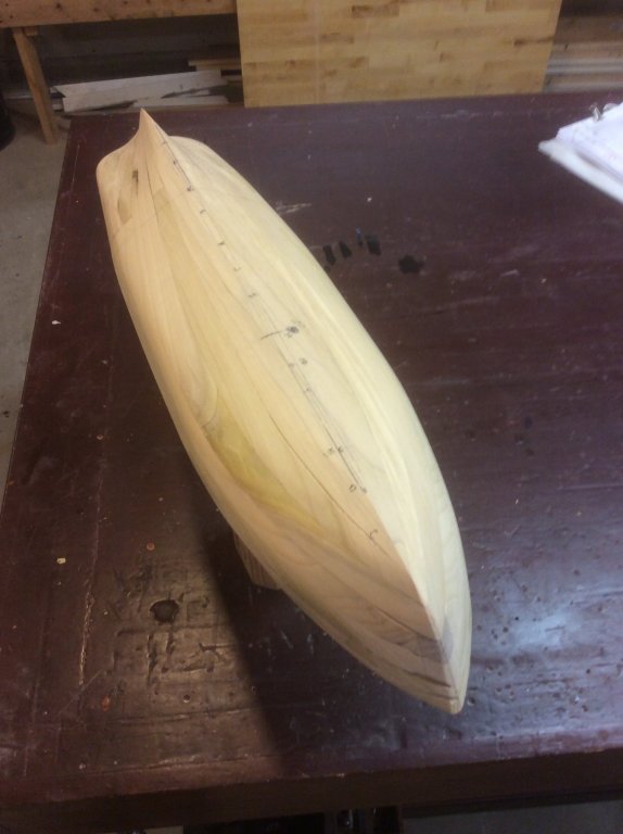
I have had the worst luck with keels on my builds. One came off, due to insufficient glue area, I think, and another split twice during the build. I was determined that the keel on this build was going to be more robust. I cut then chiseled a 1/4" groove down the centerline of the hull and inserted a piece of cherry that I had leftover from a cabinet project.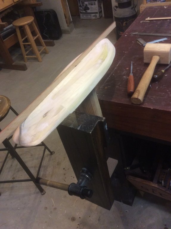
I used the same material for the stem and stern, a secured with glue, clamps, and a few trenails for good measure.
Ill do further shaping and sanding down to a more scaled width before planking, but for now these element remain capable of great abuse.
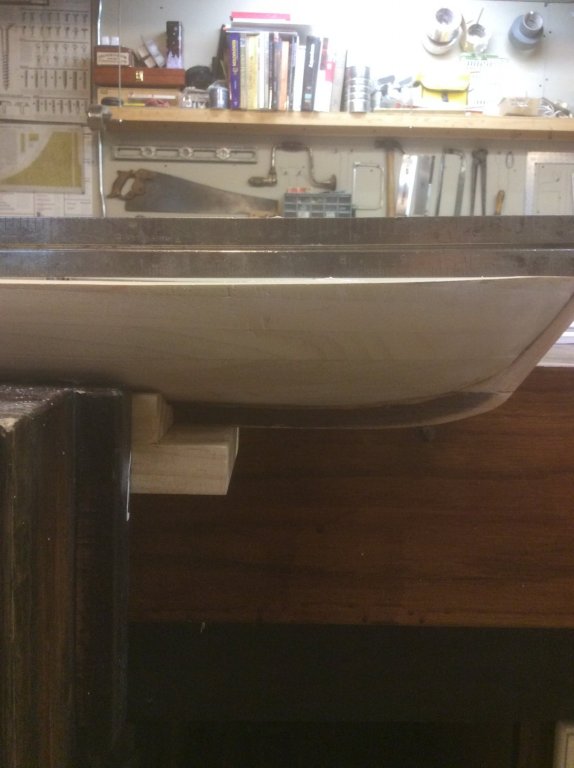
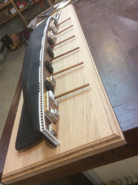
After adding the keel, I added a strong mount to the bottom of the hull so I can hold the model in a vice while working topside.
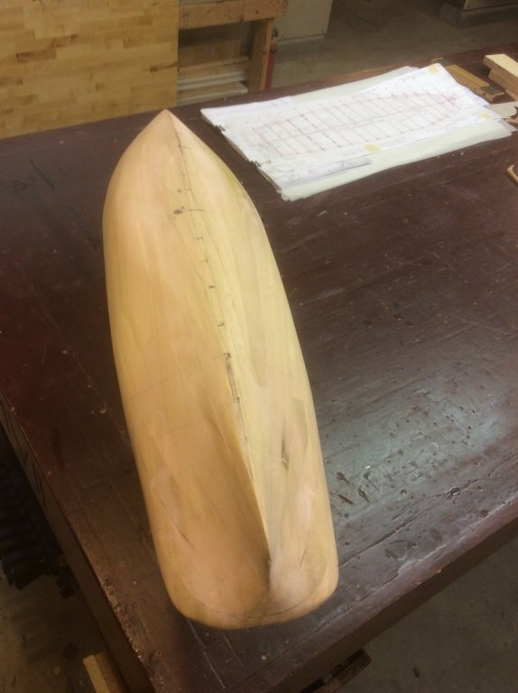
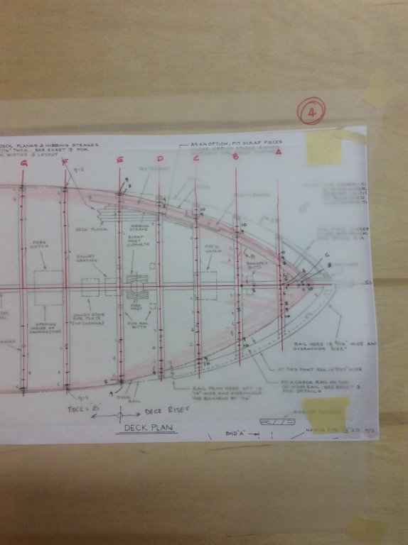
Going topside now to address the development of the bulwarks. When I fashioned the hull, I excluded the timberframes above the deck, and shaped the hull out to the sheer line. Looking at the drawing detail, the outboard edge of the waterway abuts the inboard edge of the laser cut bulkhead timberheads.
So, if all turned out according to plan, when I used dividers to measure the plan distance from ship centerline to the waterway and transfer the location to the hull, I should have a bit of hull showing outboard of the outer edge of the waterway.
Hey! Not too bad
Oh-oh. Looks like I'll have to do some fixing at the bow.
I soaked a couple of waterway extension strips and glued to the waterway to provide the base from which to build up my bulwarks.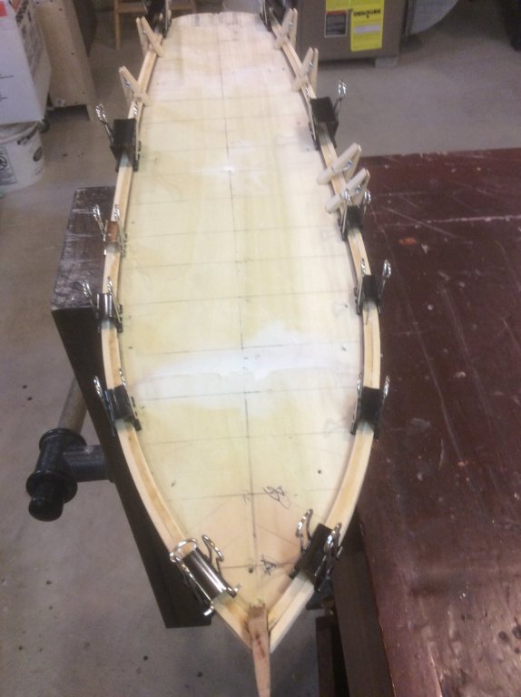
This put the sheer line beyond the hull at the bow as seen from below, so I'll have to return to this problem later. Over-zealous working with that bench plane, I guess (I just love those curly shavings flying when I get a rhythm going).