


petervisser
-
Posts
505 -
Joined
-
Last visited
Content Type
Profiles
Forums
Gallery
Events
Posts posted by petervisser
-
-
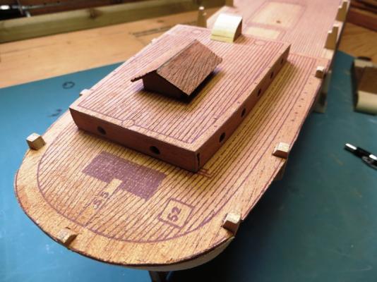
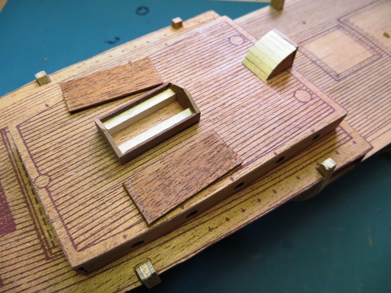
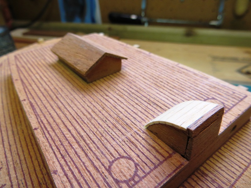
Here's the assembly of the skylight and companionway...
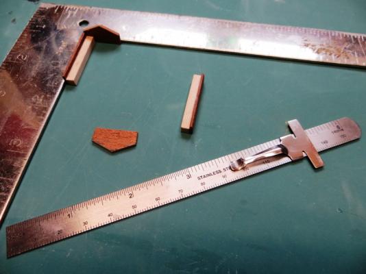

-
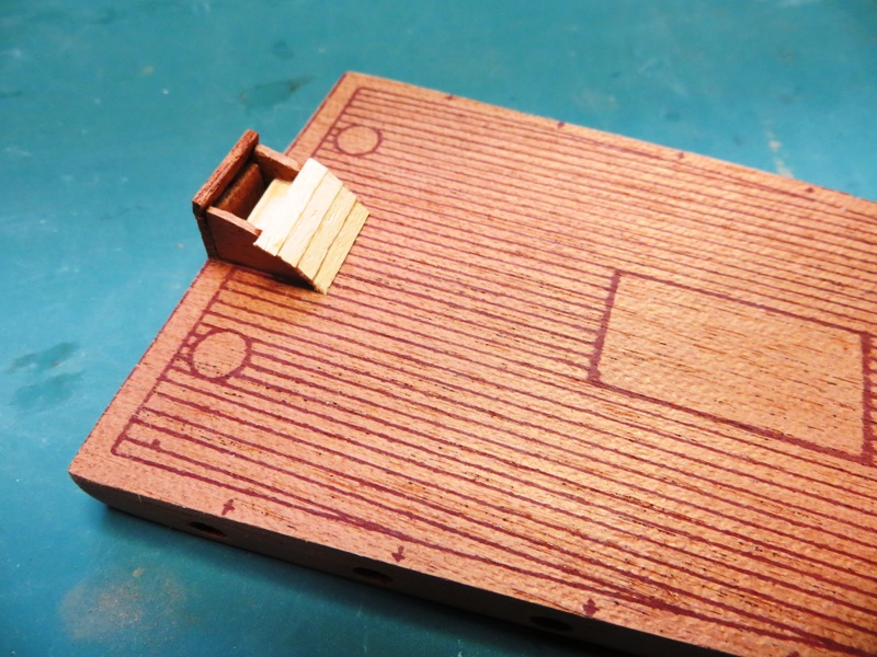
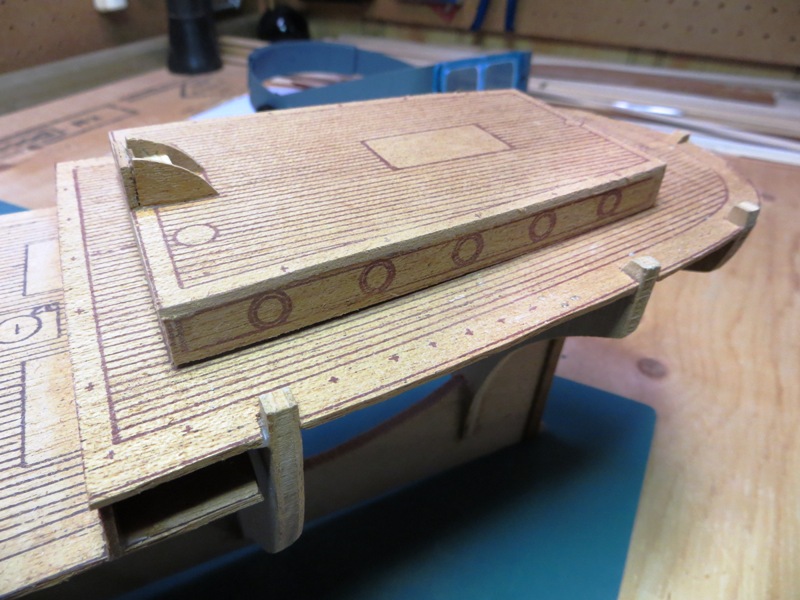
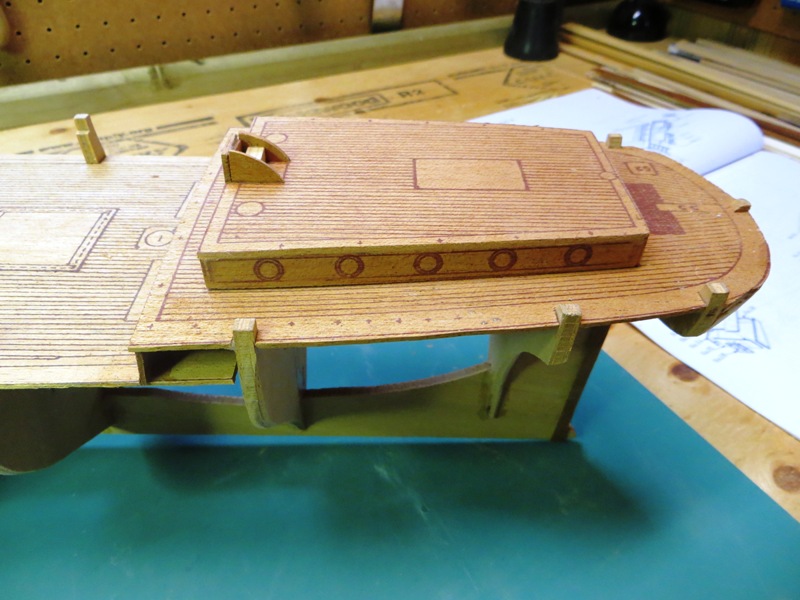
The coamings of the cabin roof did not fit flush onto the aft deck so some modification was required. Here's how I did that..

Here you can see the gap between the deck and the coaming.
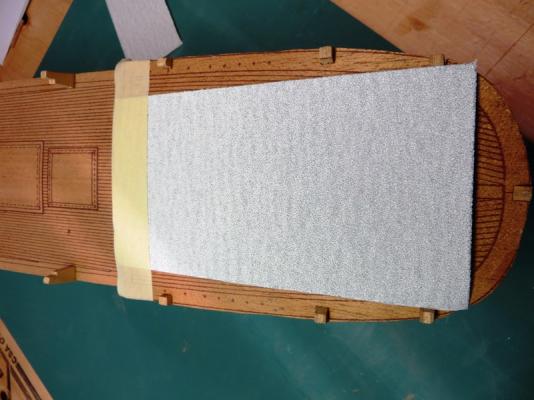
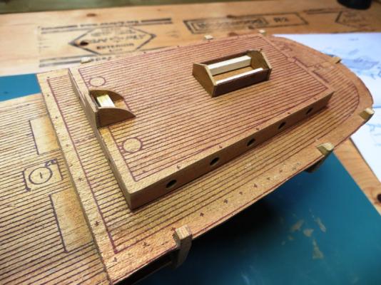
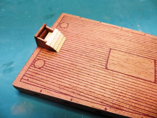
Then I laid a sheet of sandpaper on the deck and skidded the coaming fore and aft along the sandpaper to introduce the camber into the coaming assembly.
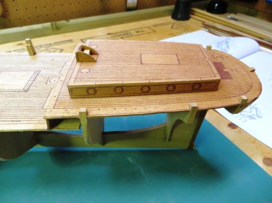
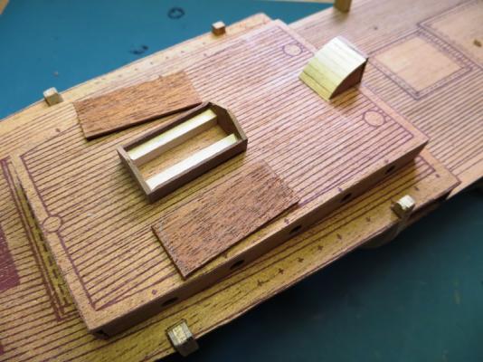
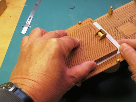
Now the coaming makes full contact with the deck.
- maddog33, thomaslambo, hof00 and 3 others
-
 6
6
-
Hi guys,
Thanks for looking in and the encouragement and ideas. It's much appreciated!
After lots of consideration on where to start, I decided to tackle the after cabin roof of all things. I thought I would make the deck planking the first job on the build. And then I was thinking about the camber the deck has and how the deck houses would be installed. With the absence of the deck planking I could assemble the various deck structures and sand the cambers into them. I will demonstrate later with a picture.
So, here goes....

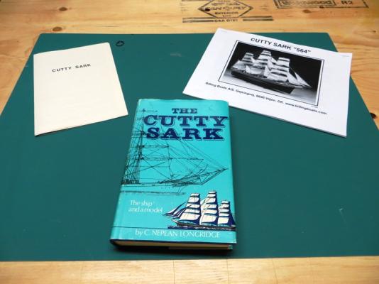
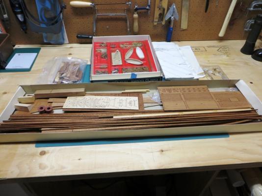
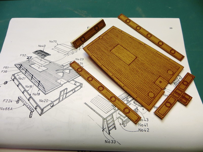
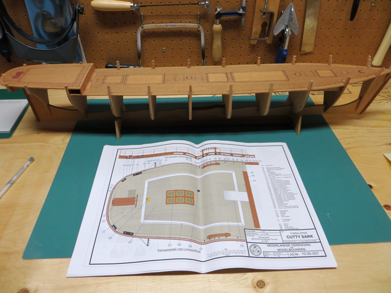
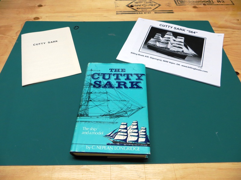
I have decided to use as much of the material supplied with this 50 year old kit and build it much as Mr. Billing intended. The "pieces" are not laser cut but inked onto sheets of mahogany, which must be cut out manually. I have a modern day version of Billing's instructions for the current Cutty Sark kit which you can see in the photo. The instructions that came with the kit I have are minimal.
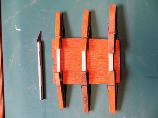

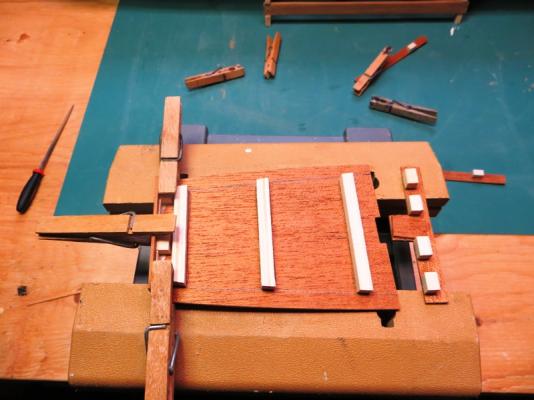
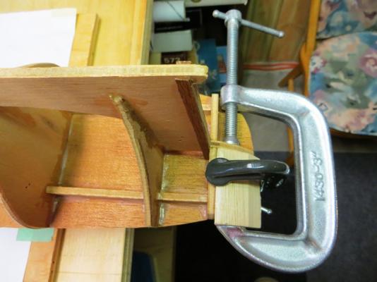
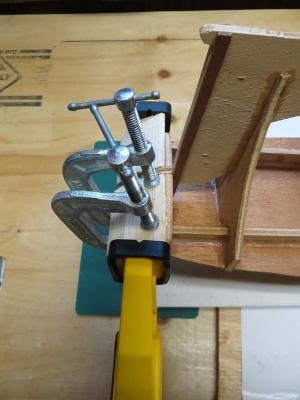
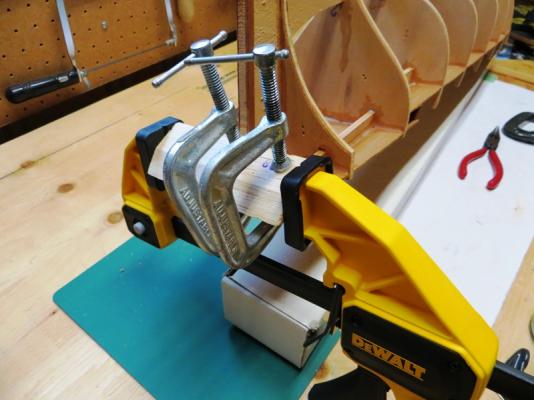
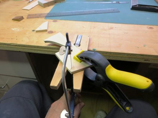
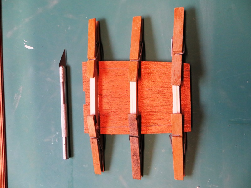
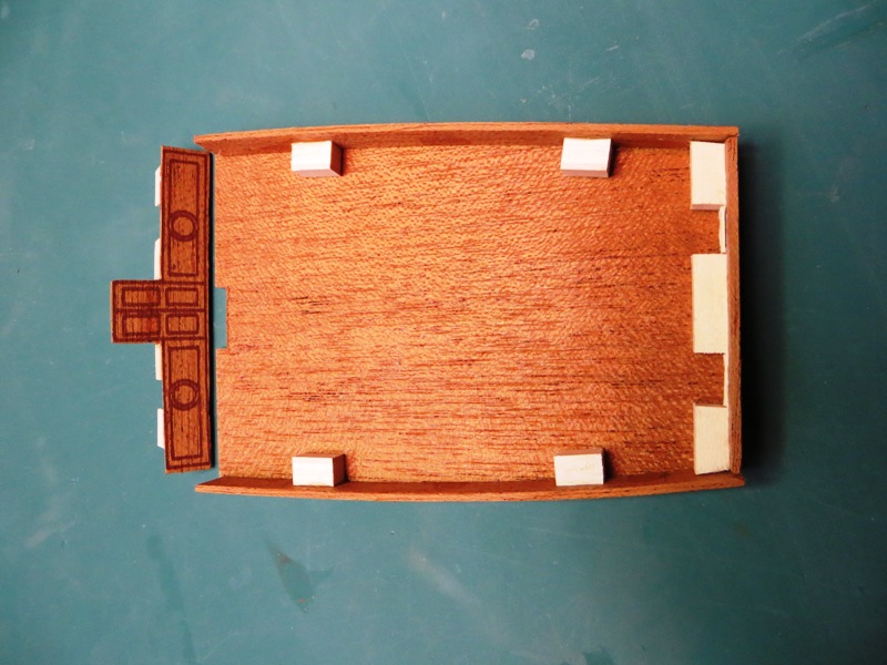
I prepped the various pieces for assembly. This entailed adding blocks of wood to the edges of the sides so that there would be more surface area to glue the pieces together. Also the cabin roof was a bit warped so I glued some "beams" on to straighten it out.


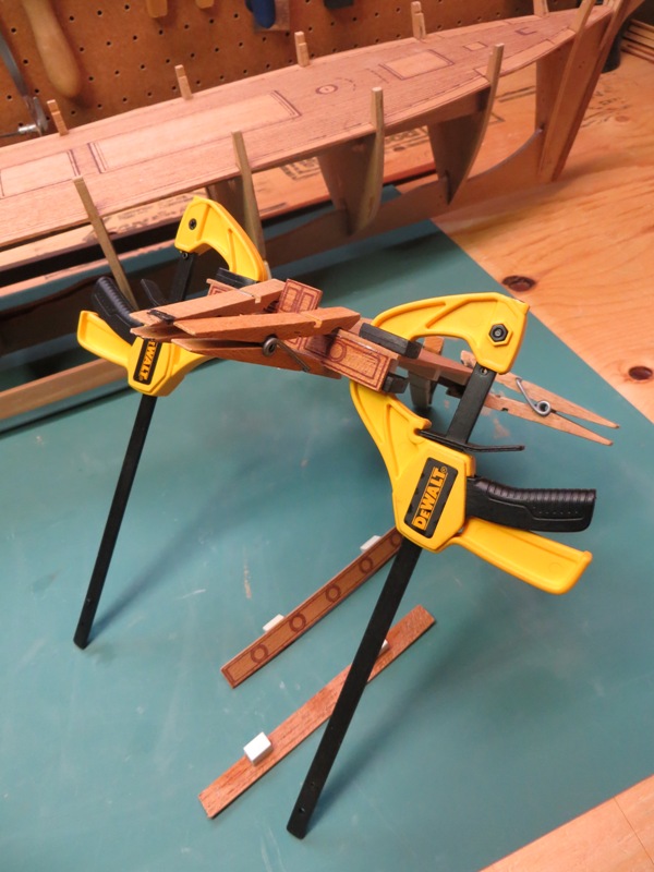
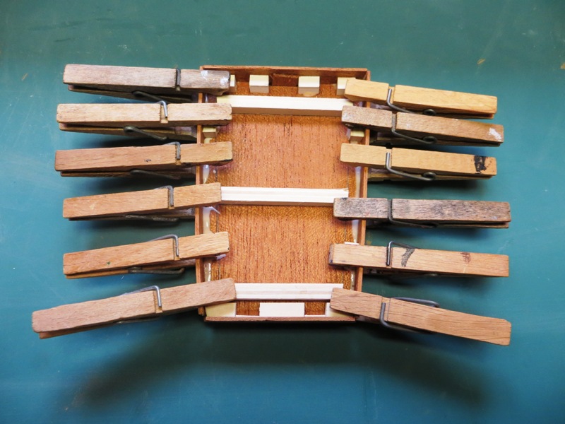
Here, the sides, front and rear coamings are added to the cabin roof, using high tech clothes pins. I have also purchased the clamps recently and they are awesome! My new favourite tool!
-
-
Hallo Jens,
I am also building this old kit, that I received from a friend. Mine has the even older mahogany wood for the hull planking which I will be replacing. I enjoyed looking at your build. You have used some original techniques which add alot of interesting details.
Thanks for posting your log.
Peter
- Altduck, Elijah and popeye the sailor
-
3
-
Hi Ian,
The binnacle is a great addition to your model! Lovely work.
As for the bulwark, I would lean towards a wood dowel of sufficient diameter instead of the brass rod. They are easier to hide I think and easier to sand to the correct length. Just an idea...
Looking forward to your final solution. Good luck!
Peter
-
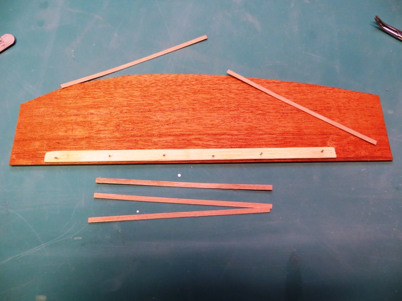
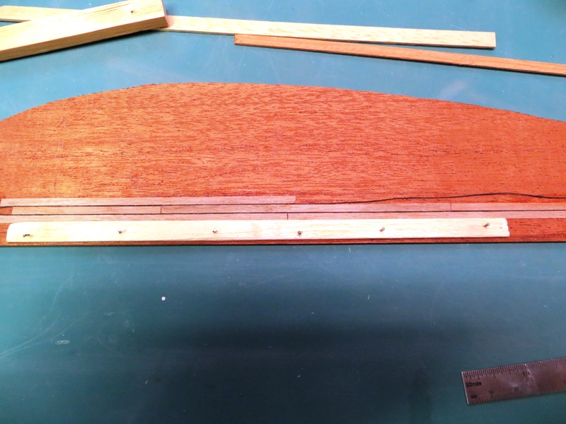
The next big step to tackle is the decks. This is an old Billing kit and the decks consist of sheets of mahogany with the planking inked onto them. Less than ideal to say the least. So I purchased a tube of cherry strips from Lee Valley which are 1/8" wide by 24" in length.
I decided to experiment with them to see how they would look on a scrap piece of mahogany and how best to apply them. Here are the results...
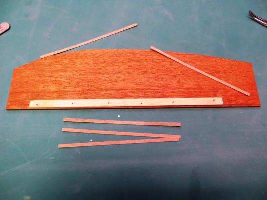
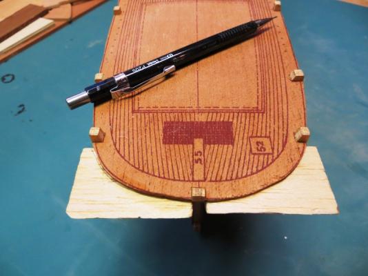
I first attached a plank that simulated the centre plank I will use as a guide on the actual false deck of the model. There are just pin nails holding it in place.
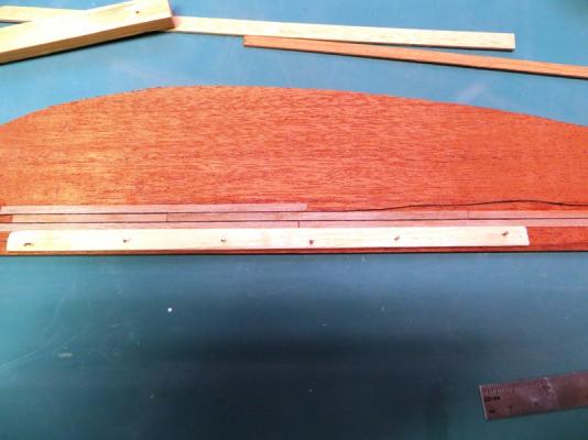
I buttted the first cherry strips against the reference plank, and then laid a black thread against them to simulate the caulking. Then repeat as necessary.
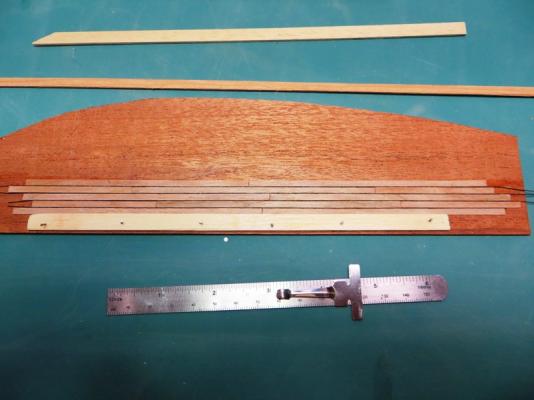
The experiment worked and I will use this method on the model.
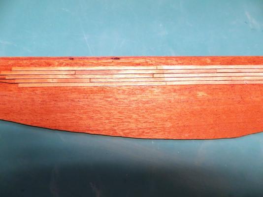
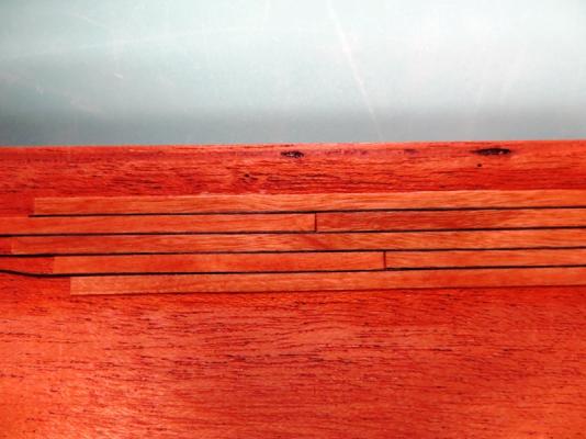
I then applied three coats of satin varathane on half the planks to see if it improved the appearance of the wood. I liked the richer colour and it also brought out the grain a little.
Now, onto the real thing!
Peter
- heksanol, Piet, thomaslambo and 3 others
-
6
-
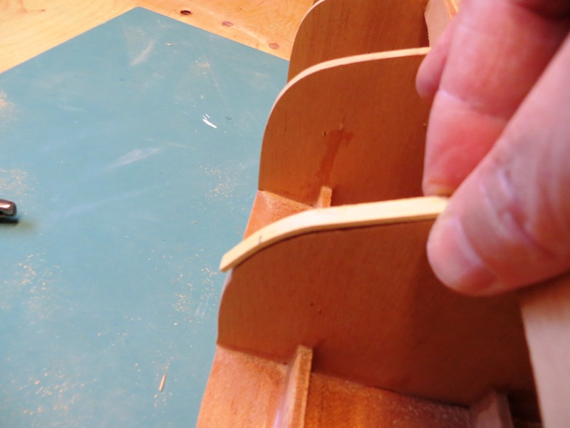
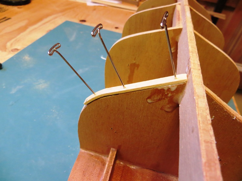
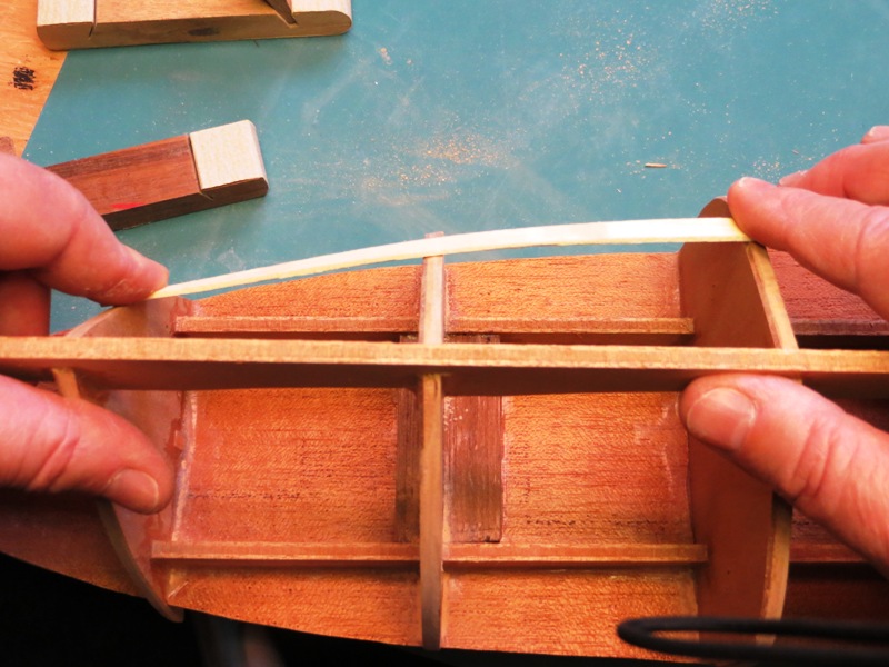
I ran into an issue with one of the bulkheads. The previous owner who had started the model, sanded off a bit too much of frame #4 when he was fairing the hull. I could see this when I was checking the beveling, as seen in the following photo.

I decided to add a fillet in order to fill the gap. Here's a couple of photos showing that process...

]


I ran the plank along the the offending bulkhead and the adjacent ones and all is well! I will commence the hull planking when the deck is finished.
Peter
- Piet, popeye the sailor, ianmajor and 1 other
-
4
-
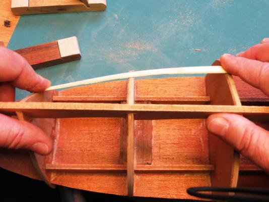
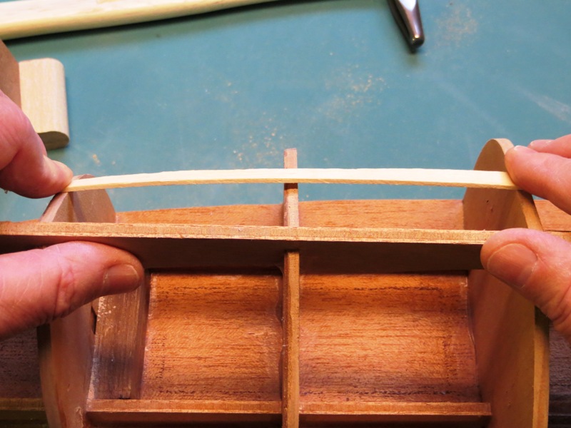
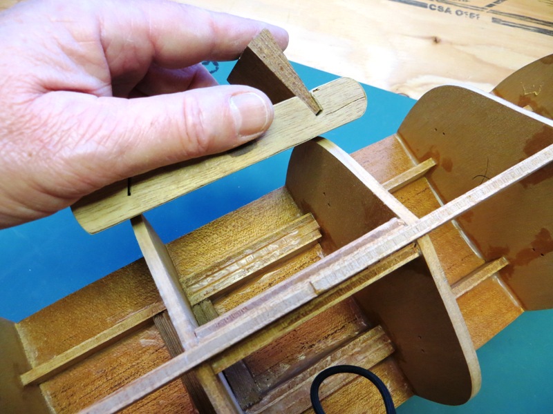
Next up, fairing the bulkheads. This is something that needs special attention in order to have a smooth looking hull. I have always used a couple of sanding blocks (a wide one and a narrow one) made by Exacto which work really well. By running the sanding block lightly the length of two bulkhead (keel to deck) it bevels the edges. I bevel two bulkheads at a time, then move on to the next one and bevel that pair. In this way every bulkhead is fair to the one immediately fore and aft of it. Using a shot piece of plank I check the beveling of three bulkheads in order to see the results.
Here's a couple of photos showing what I mean.

-
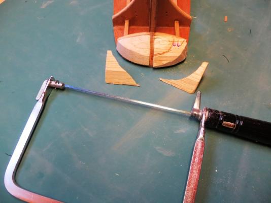
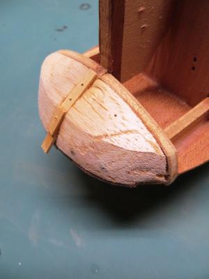
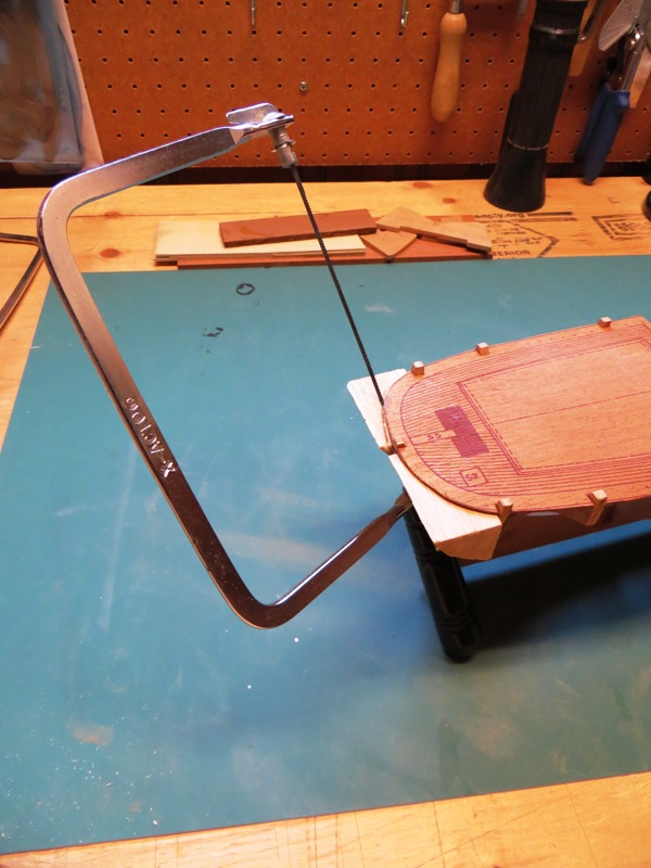
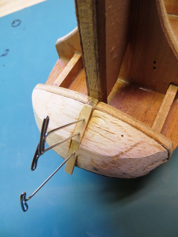
Once the blocks had a chance to set overnight, I could trim off the excess. I used a coping saw to get the bulk of the excess wood off and then sanded off the rest.
Here are a few photos of the process.
This is a mistake in the making. I started sawing from the wrong direction. I should have started at the side, instead of the stern. I couldn't really see where my blade was going, and where it would end up. In essence, I removed too much of the filler block. I simply glued the wedge I sawed off back onto the model, let it set overnight and re-sawed the wedge off again. The other side went off without a hitch.
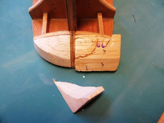
You can see the initial cut on the right with the wedge glued back on.
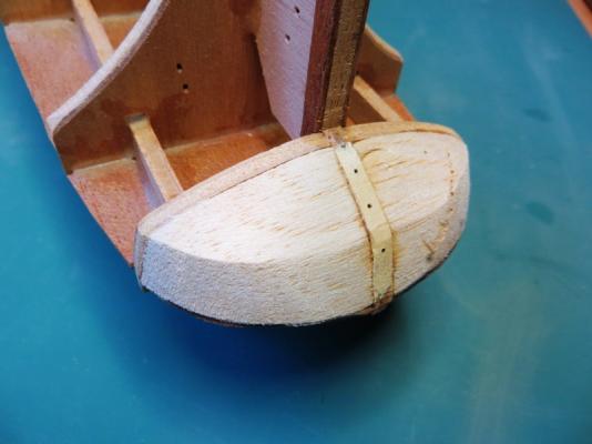
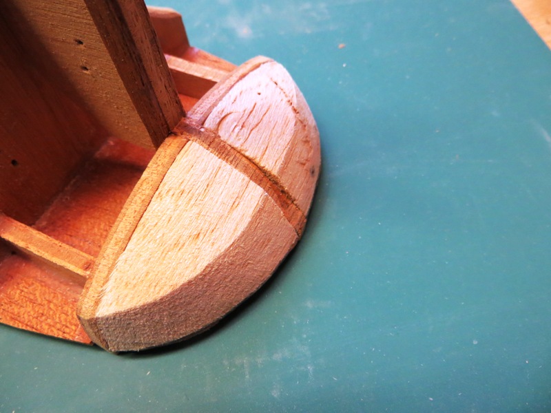
Here both filller blocks are sanded to shape. However, the stern timber is somewhat recessed. I didn't want to sand off any more of the balsa, so decided to fill in the gap.

 [
[
-
Thanks for all the encouragement gents. Yes, there are a few CS projects on the go and I have been watching a few myself. It's always nice to get ideas on different ways to skin the proverbial bird in the bush...
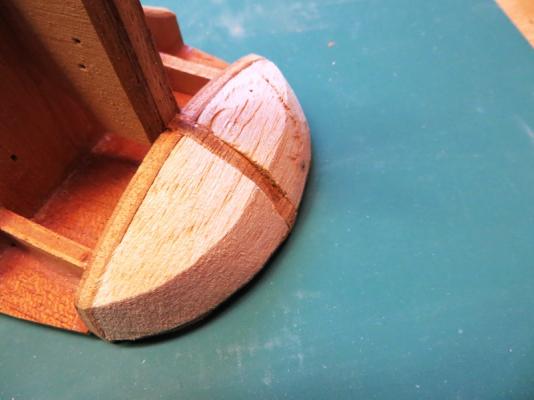
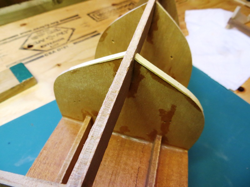
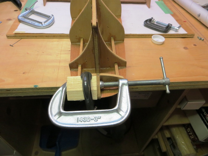
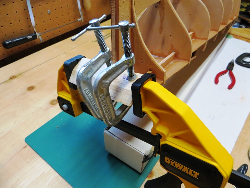
The next order of business is to shape the filler blocks on the stern to coax the hull planking in that area. The kit provided a pair of balsam blocks that were somewhat pre-shaped. All that was needed was a bit of glue and a few clamps to hold it in place initially. Here's how I went about it...

-
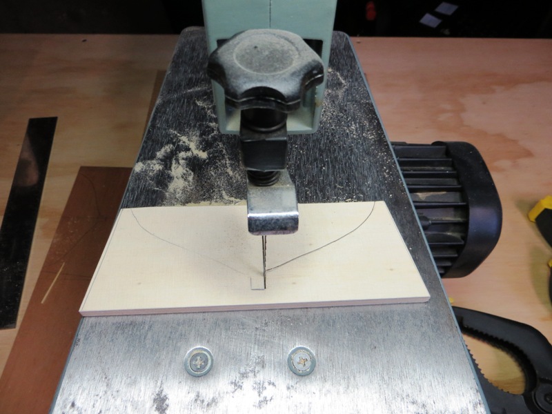
Now for the sawing..

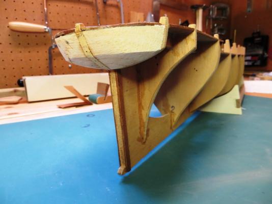
And here is the finished product, in action no less!
More progress coming soon! Happy New Year everybody!!!
Peter
-
Well, after a particularly long hiatus from model boat building, I am very glad to get back into the wood shop and make vast quantities of sawdust.
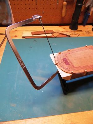
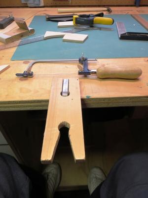
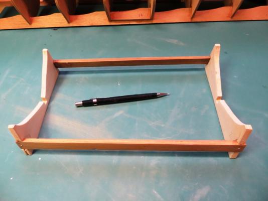
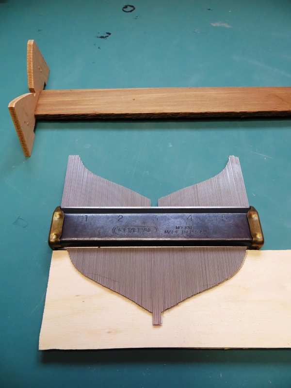
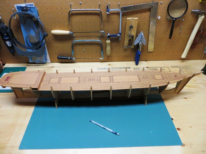
The first order of business is to build a sturdy cradle in which to hold the ship while I plank the deck. The kit had already been started by the previous owner, but it did not hold the model well. So, the cradle was built to "warm up" with some tools and skills!
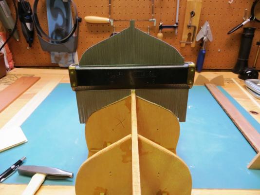
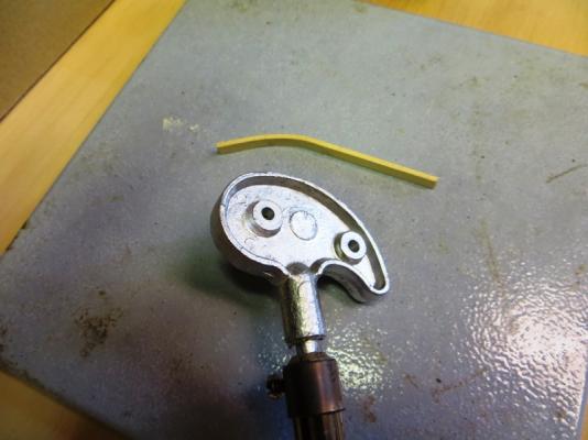
The contour gauge was placed on two of the bulkheads which are meant to "cradle" the carcass, as seen in the photo.

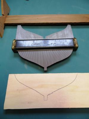
The contour gauge was then placed on a sheet of ply and the outline traced.
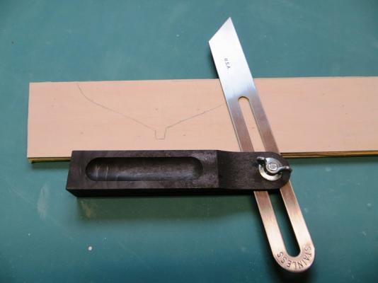

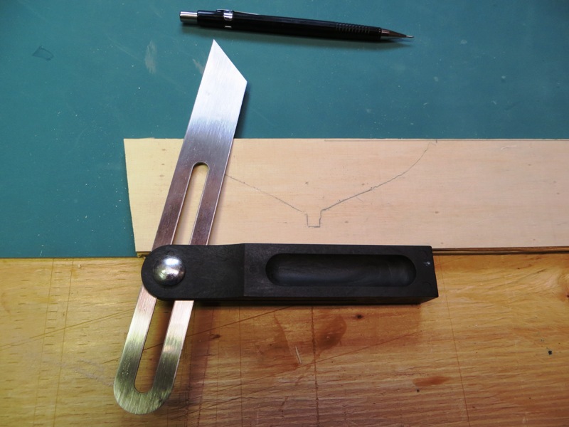
The sides of the chocks were then drawn on the ply as seen in the photos.
-
-
Hi Don, and congratulations on a beautiful ship! I just ran across your log tonight and am glad I did.
I would love to see it in person too, and help you christen it. I come home in a few weeks.
Cheers,
Peter
-
-
-
Hi John,
I really like what you've done with your Unicorn. A nice clean build! I wonder what railings with hammock nettings would look like? I'm not even sure if it would be historically accurate. But hey, you're the shipwright/skipper/bosun. You can do as you like!
I will look in from time to time and see what you decide.
Peter
-
Hi Chuck,
I am really enjoying your Cheerful unfold. Beautiful craftsmanship!
My question is, the wood you are using for your hull planking. Is it boxwood, and could you recommend a a supplier?
Cheers,
Peter
-
Hi Guys,
I thought this was a Aubrey / Maturin / O'Brian thread. It's already been cleaned up once of other authors works. Could we please keep it on topic?
Peter
-
Hi Phil,
Great work on your Bounty! You have done a fine job with the rigging. It looks really authentic and detailed what with all the seizings. Where are you getting the rigging info from? Not Billing I'm guessing...
Peter
-
Hi Nenad,
Actually, that article is already written. With Banyan's (Pat) help, I wrote a series of posts on building a display case. He converted it into an article on the NRG's Ship Modelling Resources page, under the Ship Modellers Database of articles, Furniture and Fittings.
Keep in mind, the display case is pretty rudimentary in its construction. The wood I used is easily accessible and inexpensive. I am no finishing carpenter and have only basic tools. But the display case is functional and it finishes up pretty well. With different woods and more refined skills, one could fiddle with the design and build a better one.
Here is a link to the article. Hope it helps.
http://modelshipworldforum.com/resources/furniture/Building_a_Display_Case.pdf
Cheers,
Peter
-
Hi guys,
Thanks for the warm welcome from the Cutty Sark Club. There certainly are a fair number of Cutty Sark builds going on and I have been following along with yours from the wings.
I am currently busy with building a couple of display cases, so my build log won't truly take off for a couple more weeks. But I can't wait to get it going proper. So please be patient.
Cheers,
Peter
-
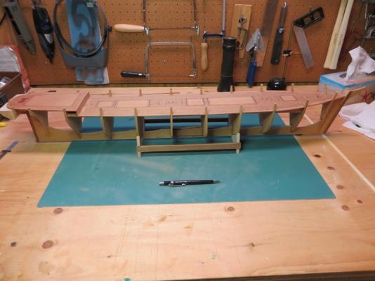
Here are a few more pictures of the model as it looks now.
I have also downloaded the building instructions from the Billing web site that include step by step building sequence drawings. They will help.
The kit number on the box is 459 which will give some of you an idea of the age of the kit. The fittings kit is #1080.


Cutty Sark by petervisser - Billing Boats - Scale 1:75
in - Kit build logs for subjects built from 1851 - 1900
Posted
The skylight needs glass and for this I use a floppy disk. And you thought they were obsolete!
I simply glue the disk onto the skylight roof. Easy-peasy!
Here it is finished.