Walter Biles
-
Posts
356 -
Joined
-
Last visited
Content Type
Profiles
Forums
Gallery
Events
Everything posted by Walter Biles
-
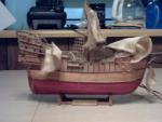
 How long is your Titanic model and what material is it I saw in the picture a way back there? I had thought about building one of those for RC once. I never found the right size. Walt Biles
 -
Michael, Originally, I put an eighth" planking then another 1/16" so I could have the better planking coverage. When I did the float test, I put enough weight in it for the masts to stand up, then gave the mast a tilt until the waterways started shipping water. When I released the mast, it went over almost that far to the other side and back 3-4 times, so I concluded that since I was already with the waterline 3/8" below the water line, that I was going to need to make it get rid of the rocking by making it sit up enough that I could add more ballast than I had before. I decided to build out the sides and the underside of the belly until I could get a quick return, and quick dampening of the sway. I have added 1/8" more to the gunnel, tapering out to 3/8" around and almost to the reverse curve where the keel bulb is formed. By the time I get done planking I should have 1/16" of that left all around the gunnel, over each side tapering to just past the inside curve, and tapering to 0" just a short ways past ending on the mid sides of the keel bulb. Then after I get everything faired, I will coat the wood with some fiberglass resin and some thin glass cloth with a build up of resin to where I can put a nice coat of paint all over. Below the water line, will be a red lead color, with a black line at the water, with gloss white from there up to the deck. I still need to make the stanchions and end rails so I can put on a fine line along the rail. They had a 1/4" cable through 1" stainless stantions on the real boat. I will try to simulate that. Walter Biles
- 208 replies
-
- 3
-

-
- meridea
- repair ship
- (and 1 more)
-
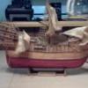
I like what you are doing with your diorama. I do feel that your big stuka on the wide edge of it would be stalling out trying to climb out at that angle of attack. I believe the nose should be maybe half as high above the tail. Most of his dive speed would be gone after a thousand feet of climb, and he would need to be able to keep it moving to climb at all. Just an observation from a former private pilot. Walter Biles
-
Thank you Michael, It was necessary in order to get the freeboard I needed. My earlier test float showed the water line would be below the surface between 1/4" to 1/2". That way I can carry the ballast needed to make sure it would self right without water entering the hull. Good to have you drop in. Walter Biles
-
I spent Saturday repairing and maintaining my tools. I repaired nearly 100 push pins by re-seating the pins in epoxy, and coating the thinner part of the heads with epoxy so I could handle them better. I used polyester thread and epoxy to reinforce my screw clamps against splitting. I cleaned and sharpened all my exacto knives, and repaired a crack in my wood splitter tool. Then I started working on another plank for my boat. I now have six on one side and five on the other. All in all, I had a productive day just fixing up a variety of things that had broken. At least now when I pick up something to use, It is more like ready to be used. I was getting a bit shy on usable push pins to hold the planks on while the glue dried, and I didn't even realize my splitting tool was broken until I was taking the blade off it to sharpen it. One of the screws that holds the blade had split the hole leaving it subject to the blade moving. I think I may modify the holding strip to brass and make that side wrap around the corner so I can redrill the screw into a more solid place. Then maybe the blade won't pull to the side like it had been doing. I wondered why it wasn't cutting as uniformly of late. Walter Biles
- 208 replies
-
- 1
-
-
- meridea
- repair ship
- (and 1 more)
-
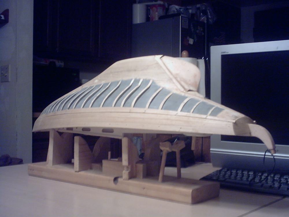
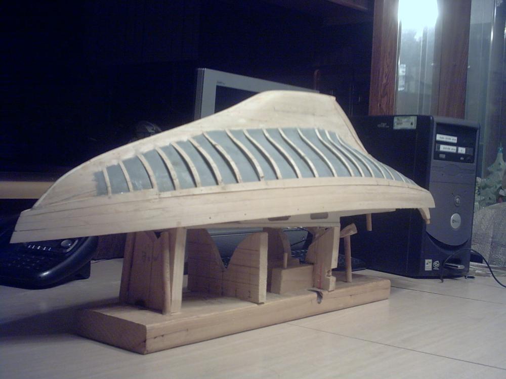
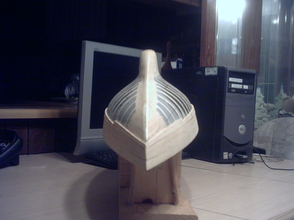
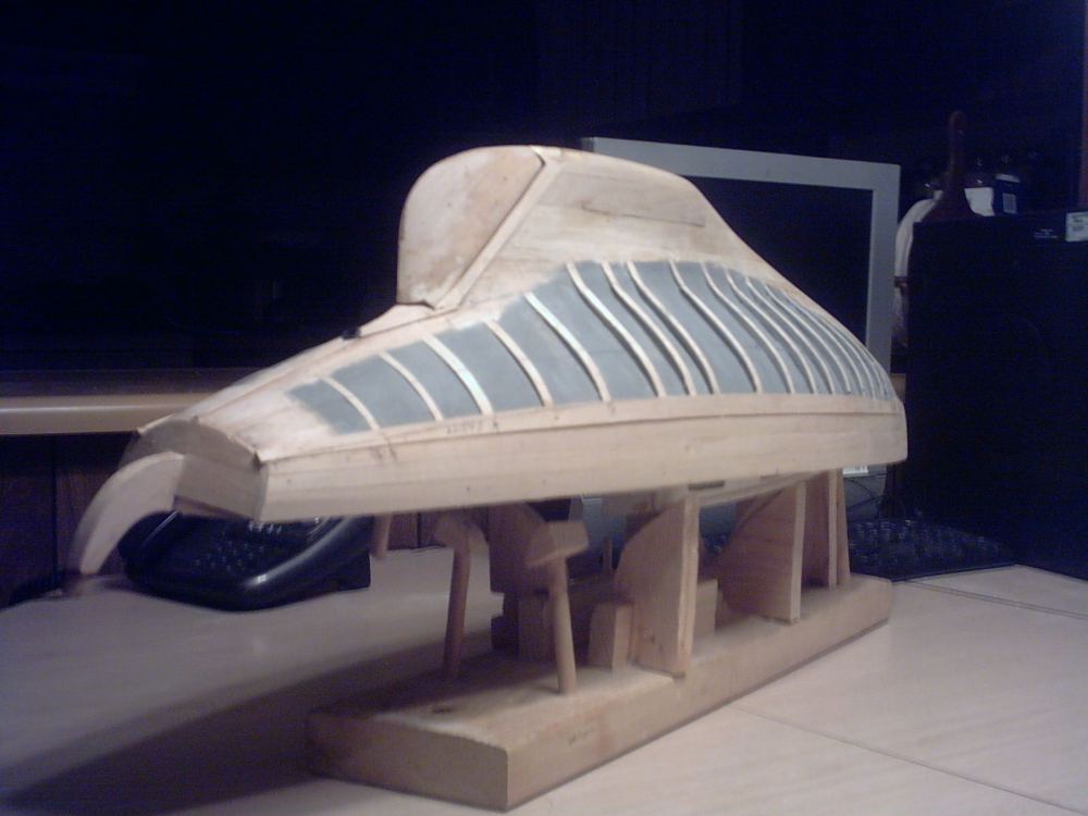
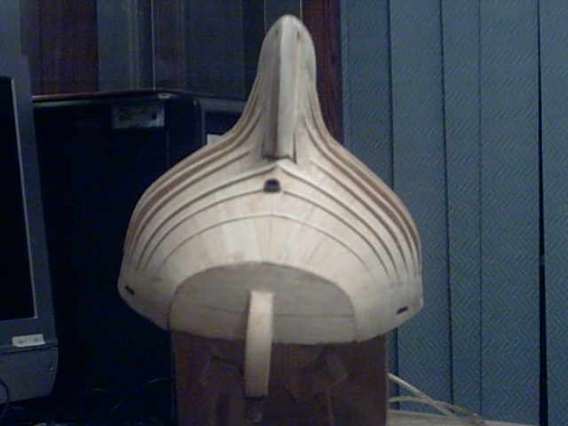
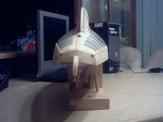
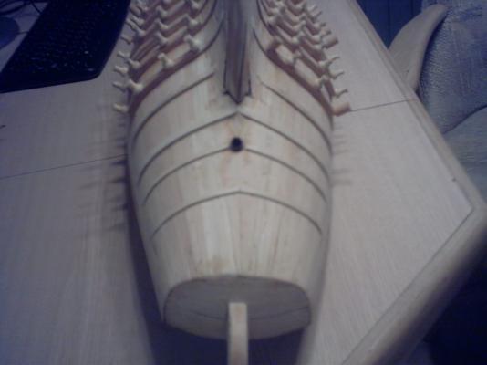
Here are my latest pix of Meridea. I masked all the way around the ribs then sprayed clear sealer over the areas. Then I put a spray primer over that to help fill any pin holes. Then after unmasking, I scraped the coatings off of where the planks would attach, and sanded and faired the ribs some more. After considering the plight I would be in if my planks went too far down the keel fin, I decided to stop all of the ribs where they arrived on the relative flat sides of the keel fin. This was done to limit thickening the area of transition from hull to rudder I have a pretty good clearance between the hull recess and the front of the rudder, with minimal clearance between the faces. If I would add anything to the outer surface of the rudder to accommodate extra plank thickness, it would mess up this clearance. The grey primer actually helps accent the recess between the ribs and seemed to keep the flash from going off and over exposing it all. Walter Biles


- 208 replies
-
- 6
-
-
- meridea
- repair ship
- (and 1 more)
-
I got a few more planks last night, I now have 4 each side, and two more cut. If I can get enough incentive I might work on it some more tonight. 2 more courses, and I will have my first section done. I will have half the radius of the hull done then. Then after getting the next section to the start of the inside curve, I will be almost done, except for the fiddly work of fitting compound curves with planks. Once I am past that area, I will be tapering all planking to zero just above the fin. I figure to leave the original planking layers from there down to keep my fin from getting too fat for a smooth transition to the rudder. I think that tonight, I may just take pictures of the progress up to where it is now, unless I get carried away. Walter Biles
- 208 replies
-
- 1
-
-
- meridea
- repair ship
- (and 1 more)
-
Fletch, I'm sorry I did not mention about the code window. If you want the pricing reflected by a code, there is a little window at the top. However, if after entering the code, you don't click on the check mark to the right, it wouldn't show except on final checkout where you would have to put it in. I lost out by paying full regular price on several sale items that way, until I figured that out. When you have the code entered with the check mark, it will show the code to the right of that in the corner area. I got pretty disgusted before I figured out what it was for. The code kept disappearing until I was in checkout, and I would have to enter it all over again. When you get the code in with the check mark during the main screen, all sale prices show instead of the regular price. Then when you get to checkout, it will show there as well. I tend to think of those things only as being from my apnea brain malfunctions, in stead of it might confuse anybody. Sorry. Walter Biles
-
Thank you all for the likes and nice comments. I have begun the re-planking. I believe it is going to work okay. I'm not working very quickly, but just taking my time. I want a good fit. I am also hoping to wait until payday before I close up where the foam should go. I now have the two top courses on both sides, and another on one side. I need to get some pictures before getting too far. Walt Biles
- 208 replies
-
- 1
-
-
- meridea
- repair ship
- (and 1 more)
-
Ed, Great work!! lovely! Walt Biles
-
Fletch, Model EXPO has been advertising it at $299 for awhile but it is a sale price, and I am not sure how long it may still be good. Model Expo has an emblem link on the main site along the right side. I think you can get through with www.modelexpo-online.com/default.asp. I looked it up. I wouldn't wait if you want it at that price It is regularly $499. You might be able to find a phone # 1-800-222-3876 on the site to confirm what discount code to use and if it is still in effect. I know I was always wanting to do the Connie and at that price it would be an exceptional buy, but my finances forbid even that kind of outlay. Walter Biles
-
Mark, Do the section at either end of that one, and sooner than later you'll have it all in sections. Great work. Beautiful! Walt Biles
-
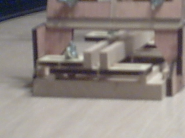
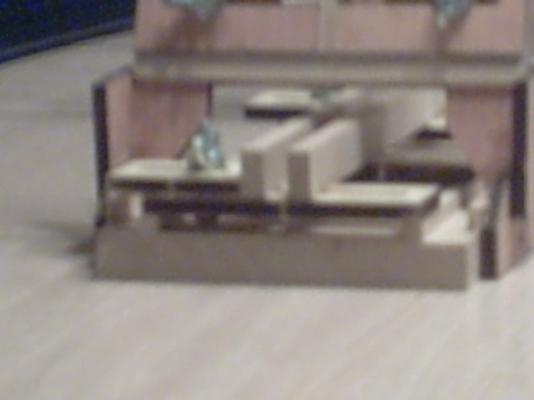
The last part about creating the key for the slot, and the locking pin from the T-washer nut, is the thing I learned from this device that I wish I had used on the first Fair A Frame project. The hold on the keel would be better if the bolt did not slip as you tighten down the settings on the keel clamp. I may go back and remove the bolts and apply the lock key and pin on those. Now I will have to drill out through the base to get the bolts out to make them work right. I want to comment that although these kits only provide the simplest of tools, I believe that each one of them can be useful for the purpose they were designed. They are kind of pricey if they are not on sale, but if you have low funding like many of us, and catch them on sale, they should work for you. They may not be the very top of the line tools, but they are kind of fun to build, and solve the problems that were overlooked. Walter Biles I will be adding more pix to improve the illustrations for this topic. If anything is not clear please feel free to ask, and I will try to provide any answers that I can.
-
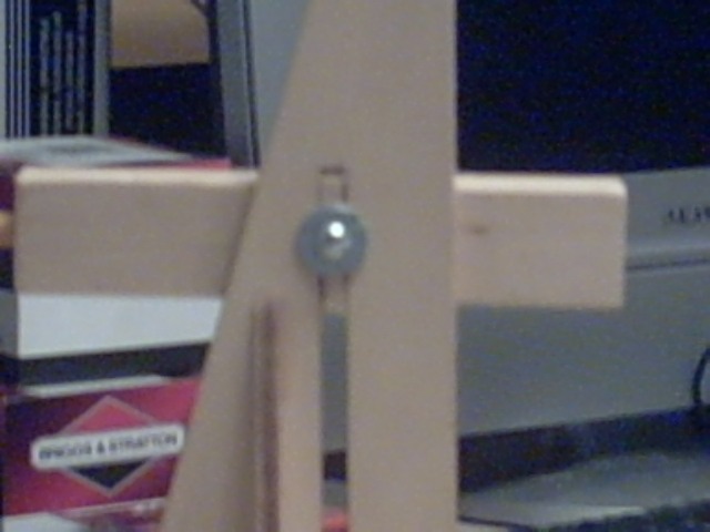
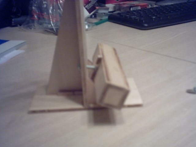
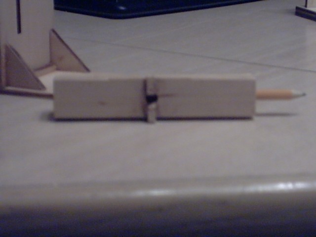
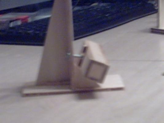
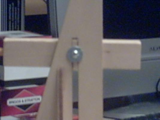
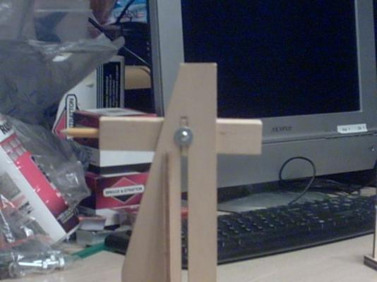
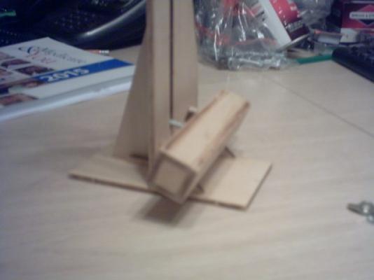
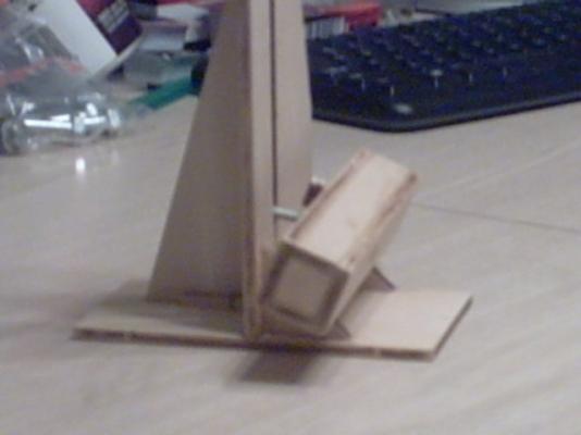
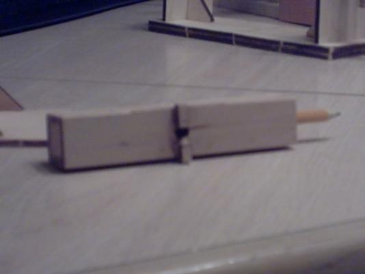
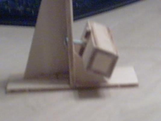
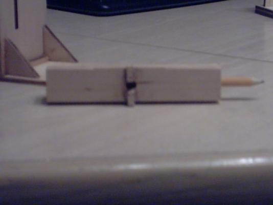
MS Waterline Marking Tool: This tool was also very easy to put together. I did discover that once I had it together, the pencil arm wanted to rotate on the bolt, so it would not have maintained it's setting well. I considered this awhile, and decided it needed a key in the slot to help keep the arm in its set position without rotation. I took a piece of the burned out plywood and cut it to the width of the box holder for the pencil so it could act as my key. You should be able to see the key in the slot in the first few pictures. I had previously drilled the bolt hole for the bolt to go through, so I got some wax paper and epoxied the key to the box holder, so it would hold it square to the upright slot. I used the wax paper over the key, and slipped the key into the slot with the glue held away from the slot. Once that set up, I removed the key and pencil holder box from the slot, and re-drilled the hole back through the key. I had previously noticed that the screw head of the bolt always wanted to slip when the wing nut was being tightened. I had a T-washer nut and since it had 3 lock pins, I bent 2 of them flat with the washer, and left one pin extended. Then I screwed the bolt through the nut threading from the washer end leaving the remaining pin to seat into the key wood I had glued to the box. I tightened the bolt down into the T-washer nut, and then tightened the wing nut until the remaining pin was seated into the key in the slot. Then I could tighten the wing nut down without the bolt turning and keeping it loose. You can see how the key was set across the box holder in the last few pictures.

-
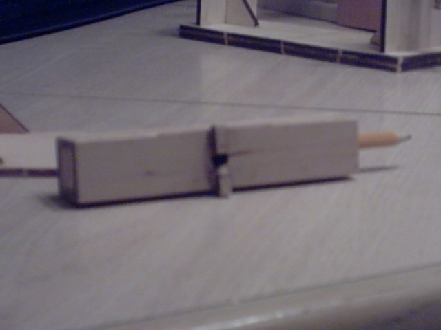
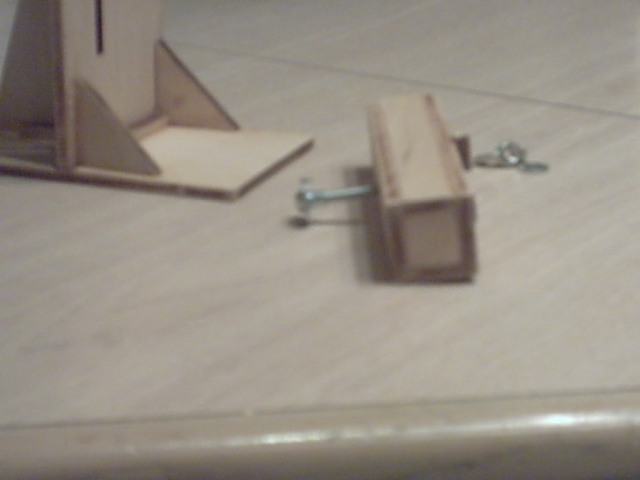
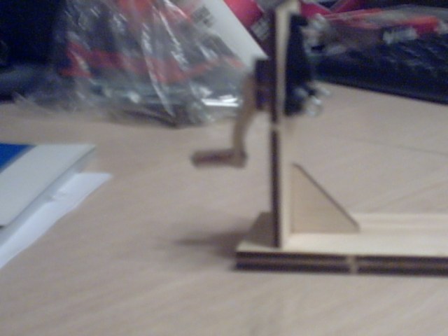
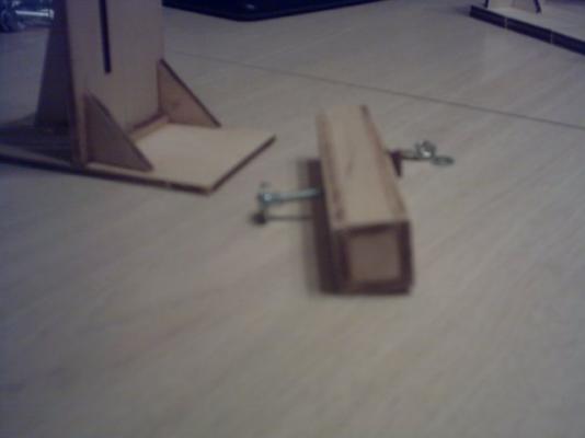
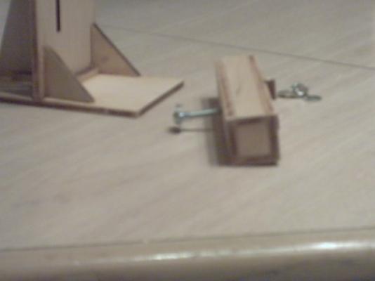
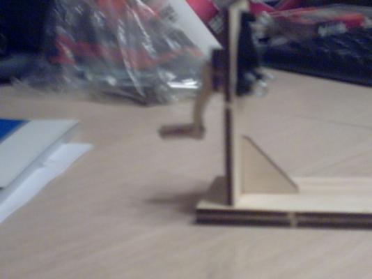
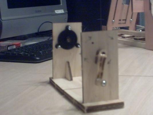
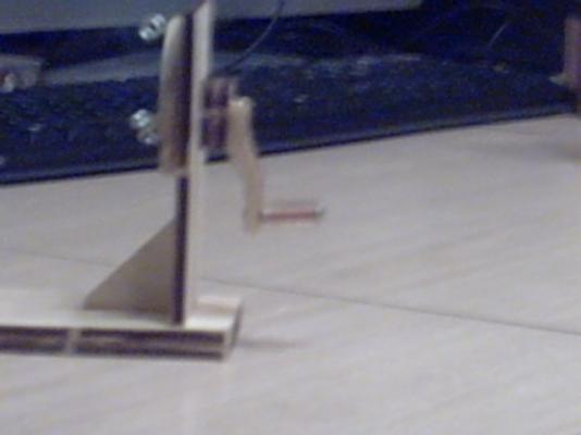
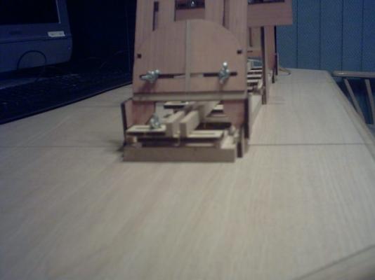
MS Rope Walk: This kit was fairly easy to understand from the drawings and the step by step descriptions, from cutting the parts free of the lazer cut sheets, and putting the frame parts together, to assembling the arms and the assembly of the gears. Each end was done before I noticed from the picture that I did not get one corner of the upright fully seated in the base slot. I deemed it not worth the effort of trying to get them back apart. Otherwise, everything came out as expected. The only thing I did was find some tygon tubing to slip over the thread over the Crank handles to make them smoother on the fingers. I tried to leave the tubing a bit loose so the shaft could turn inside it for a good handle.
-
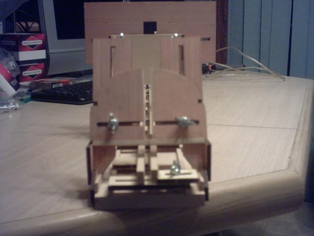
First of all, I apologize that all my pix did not come out. I will try retaking some different views and add them to this site as I get some worth using. I found the kits to be easy to understand, and the instructions to be reasonably arranged for understanding. I found that they went together fairly easily and had fairly little to give me problems in assembly. So much so, that I forgot to take pictures until they were all together on the earlier kits. These kits have laser cut part sheets with plywood being the sheets they were cut from. They had bolts, pins, gears, etc. that made it easy to put them together. Fair-A Frame: First off, I found two different spacings for the cross supports. One set was spaced on 6" intervals, and the set for the other side had a different spacing. After contemplating on any justifiable reason for the difference, I could find none. In fact, I reasoned that if they came together on the same spacings they could probably grip the keel better. So I made all of them on 3" intervals so the fixed rail was glued every 3", and in addition to making them line up better, I tested one of my hulls on it and found it had a better grip than I felt it would have had the other way. It provided more evenly spaced support for the keel as well. Please note. I put the guide slides onto the bolt system and used a metal ruler between them for alignment of the fixed side, so it was straight. Then, as I started figuring the other side, I really felt that the two holding bars should be on the same level for uniform grip. Yes the plan did call for the slip rails to hold the model to have one of them glued to the bottom adjuster guide, and the other one was shown to be mounted higher on top of the slip adjuster on the other side. I checked the travel slots for the bolts, and found that a quite thick keel would still fit within them, so I glued the movable rail so it held the strip on the end of the slider. I used the steel ruler between them as the glue was setting. I used epoxy with wax paper below to keep things from getting stuck in the wrong places. The grip rails for the keel were straight, and held well. Next the upright guides for the stern and bow went together as the plans showed. Also the center upright guide went pretty much as it was supposed to go. Now, as I was bolting the keel uprights into their slots, I noticed some spreading of the slots. I decided that if that slot had a stringer in an upright accross the bolt slots, that it should keep any spreading from occurring thereby making the whole system stronger and more accurate. In one of the following pictures, You should be able to see the light color strip I put on both plates across the slots of the bolts. Since the after end of the upright of any keel needs to be straight I felt this would be better. I did the same for each end. There was one more thing I did not do on the adjustment slots of the bolts which I found out about on the Waterline tool which I would recommend for each of these slots. Please see the waterline marker tool for that suggestion. Further information will be added for each of the other kits along with some more views as I can get them taken and entered. I thank you for your patience. Walter Biles

-
I recently acquired a kit for each of the above named tools. I built each one from the kit, making minor modifications which I hope will make each a little better, or easier to use. I have not used any of them yet, but am familiar with their purpose, and wanted to see how difficult they would be to make and use. I am using this site as a comparison of build, as well as an information source for any upcoming builders who would like to see what each kit is like, and offer some suggestions on how to make them better or easier to use. I am only a builder of mostly scratch models, and have only gotten them because I came into a great deal on them. I inherited them. So what's not to like? First I will describe each in it's turn of the build. Then I will describe what I felt could be better about them.
-
I made a full set of bulkheads printouts for Meridea, and put my expanded (by eye) lines onto corrugated cardboard, and cut them all out taking precaution to preserve a set of negatives around them so I could take them and place them around the hull at the bulkhead stations to check the fit. Then I trimmed out the final shape of the new set of rib extensions. I am going to use these for the final adjustments of my CAD bulkheads, so my displacement will be set by them once I get the planking over them. I also trimmed my stand to make allowances for the latest sizing. Then I can make a final fit from them to allow for the planking on my CAD and on my support frame. I am making allowances so that my waterline can be drawn with the boat on the stand. I still want to get some floatation foam mixture to fill in the last frame ribs so there will be no space inside for water to reside. I can fair the foam down to the ribs so I can plank up against the foam when gluing the planks to the ribs and sealing the joints between the planking. At least that is what I hope will happen. Its nice having the Admiral back home where she belongs! Walt Biles
- 208 replies
-
- 2
-
-
- meridea
- repair ship
- (and 1 more)
-
I imagine, that one could put the largest scale close to the viewer, and the closest ones to the ship could be in the same scale as the ship, which might lead the viewer to perceive greater distance from the ship and it's closer attackers giving an impression of waves of planes. IMHO Walter Biles
-
I'm here, just can't think what to say. Good looking job so far. Keep it up. Walter Biles
-
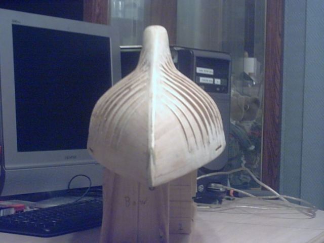
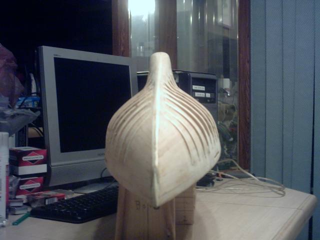
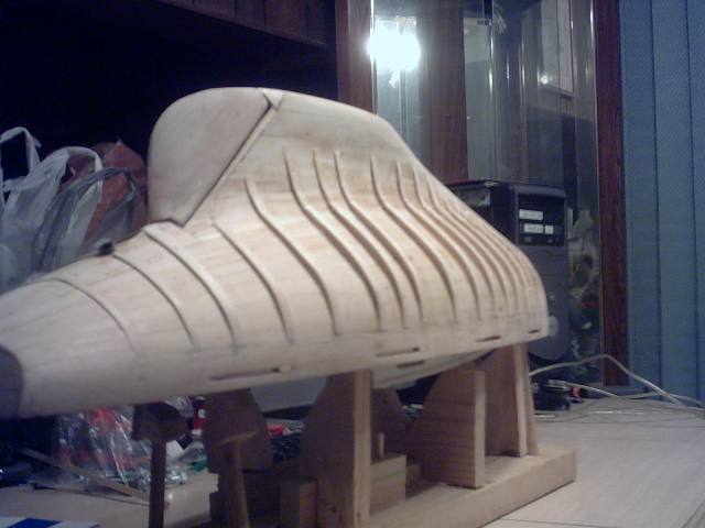
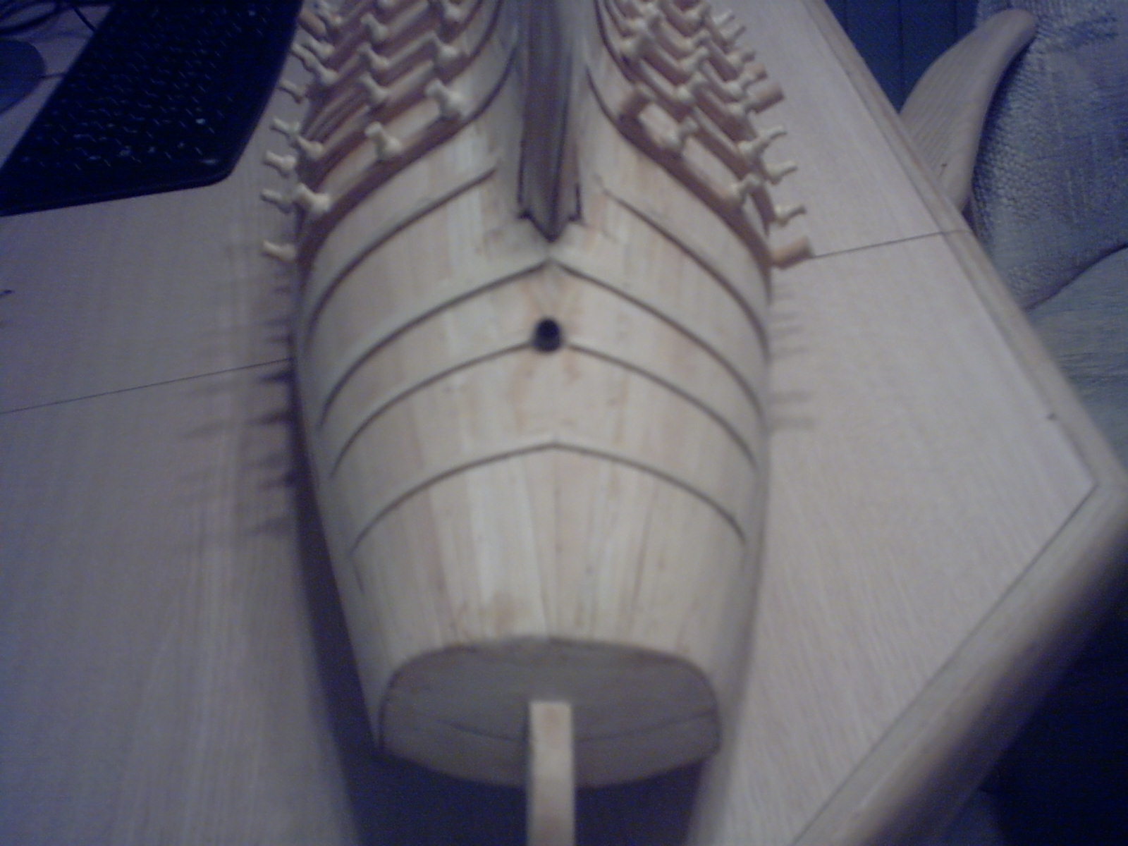
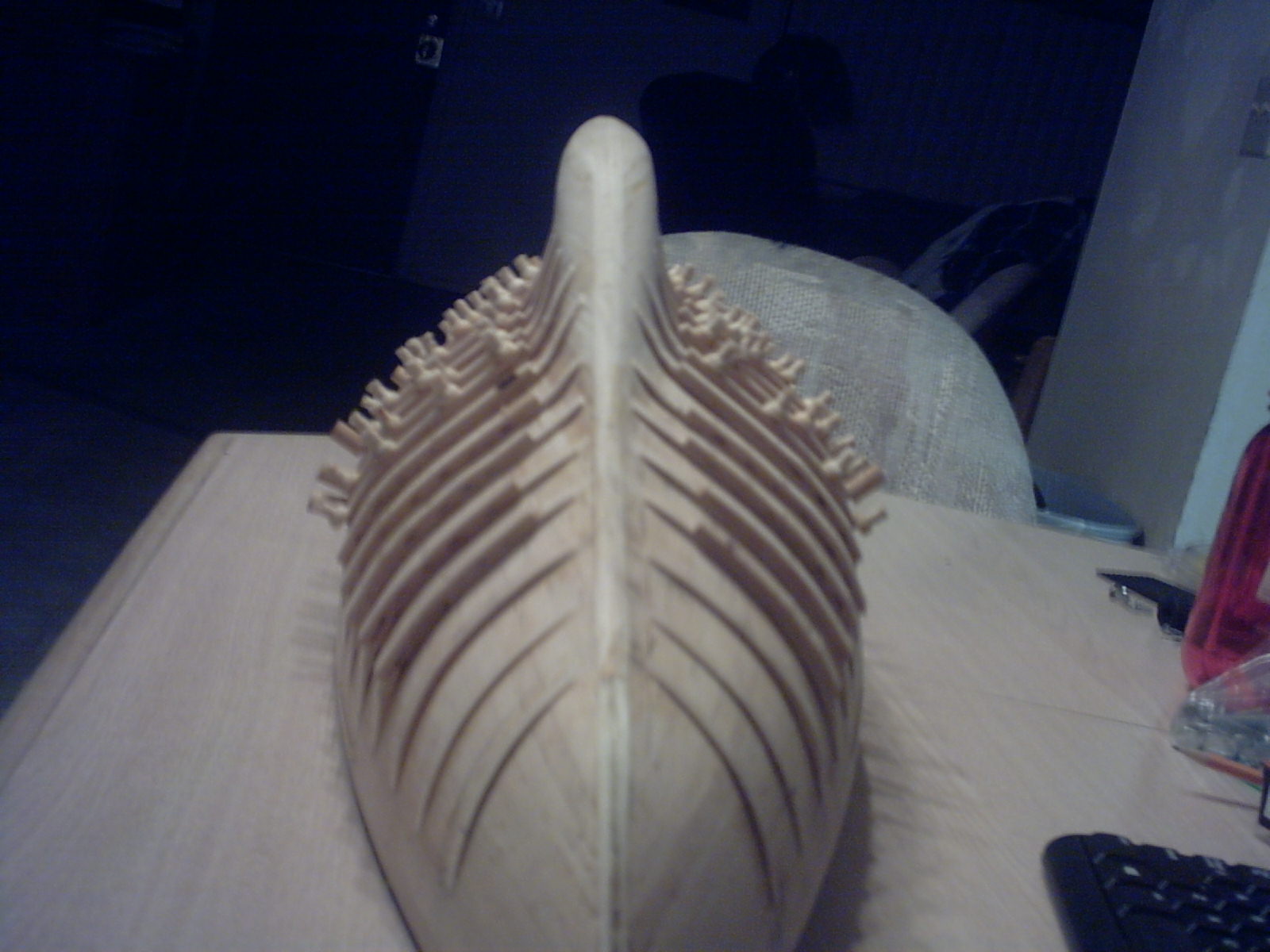
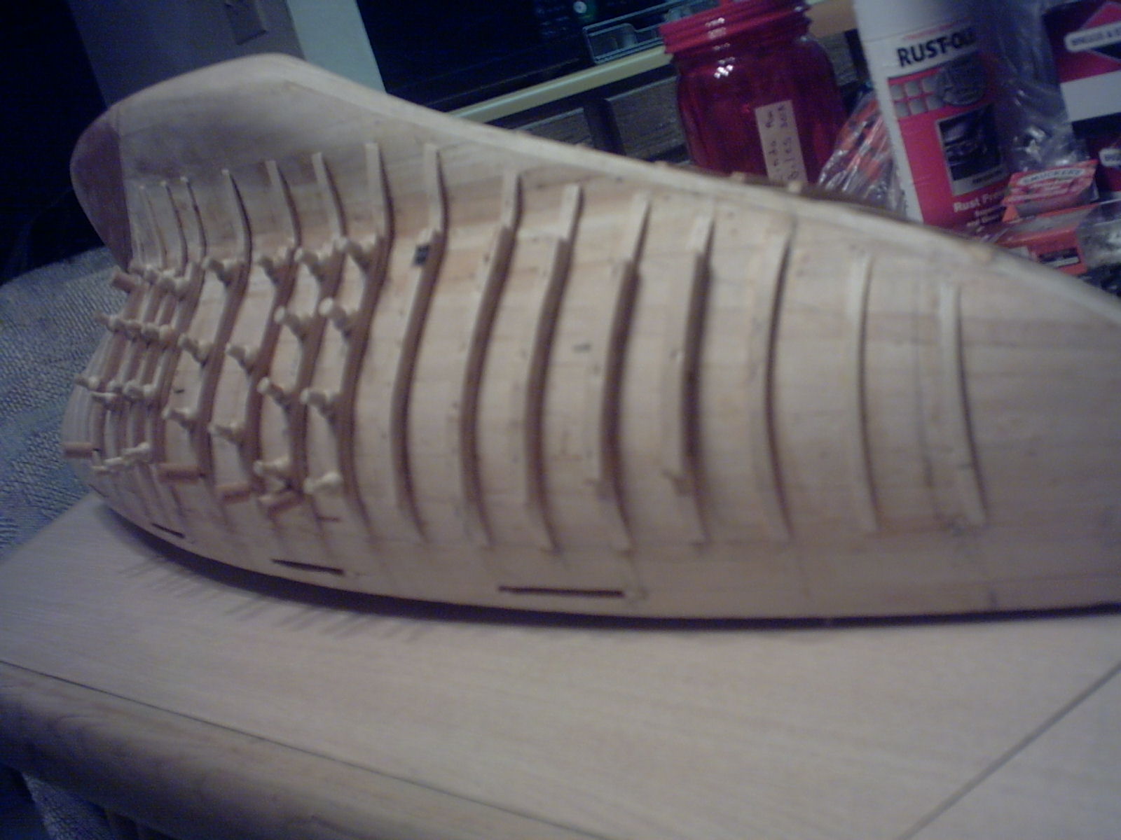
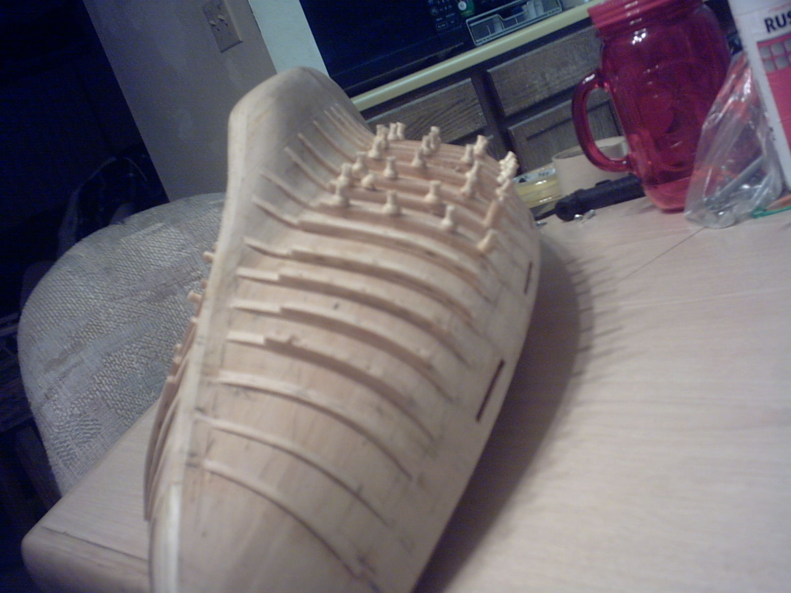
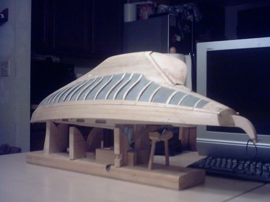
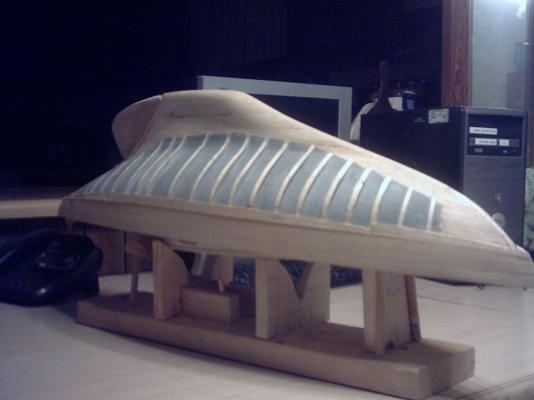
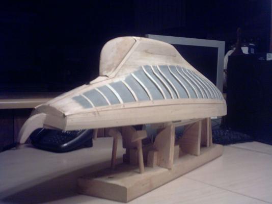
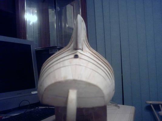
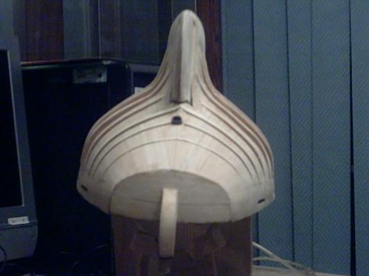
Here are the latest pictures of my Meridea with the ribs rough faired to contour. I have them grouped by views with different focus lengths and zoom to try to get more readable pictures. Enjoy! I will have some measuring and fairing to refine a bit. I will also be putting in some edge pieces to fit around the rudder for the planking to butt up against.


- 208 replies
-
- 3
-
-
- meridea
- repair ship
- (and 1 more)
-
It is good to be back at work on the boat. The new ribs are on, and rough faired, and don't look too bad. I hope it will plank well. My spacing was a bit irregular, but closer than the original bulkheads, mostly. I couldn't seem to keep them uniform without lateral bending, so I let all of them lay full contact against the hull. They looked a bit like this: ///lllll\\\ , but I still think they should allow for a good planking. Walt Biles
- 208 replies
-
- 3
-
-
- meridea
- repair ship
- (and 1 more)
-
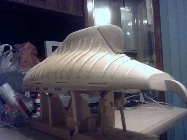
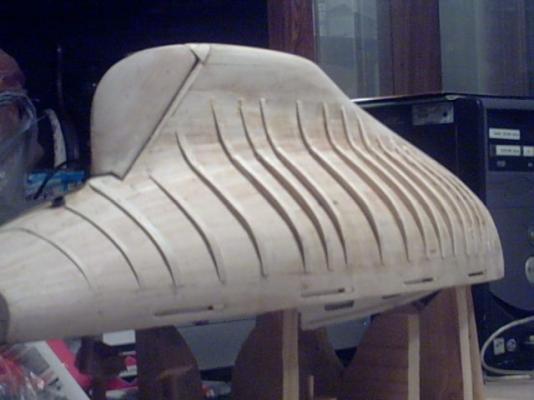
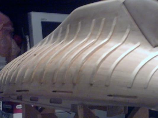
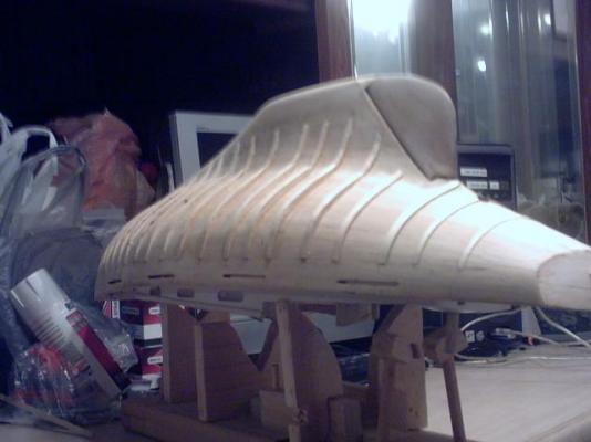
Here are the photos of the furring strips buildup on the hull of Meridea. They have just been finished adding the outer layer. As you can probably see, the first layer of strips has already been feathered down to the original planking. The next layer will also be feathered into those, and faired from the bow to the ster n. Walter Biles


- 208 replies
-
- 4
-
-
- meridea
- repair ship
- (and 1 more)
-
GREAT JOB! I especially love your brass work on the rigging. very neatly done! Walt BILES