tlevine
-
Posts
2,022 -
Joined
-
Last visited
Content Type
Profiles
Forums
Gallery
Events
Everything posted by tlevine
-

Swan class 3D model in progress
tlevine replied to dvm27's topic in CAD and 3D Modelling/Drafting Plans with Software
Fantastic renderings. Let me echo Greg's comment last month. If one is considering starting a Swan class, hold off construction until they are available.- 141 replies
-
- 7
-

-
- pof swan series
- swan
- (and 1 more)
-
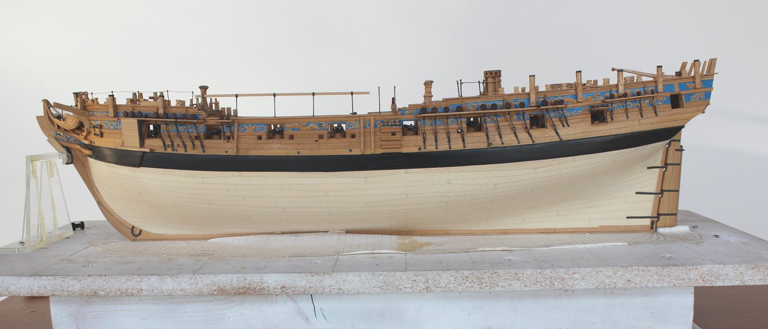
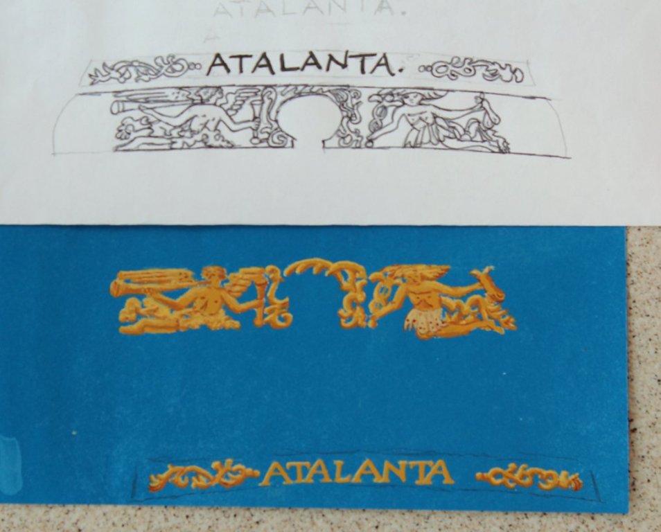
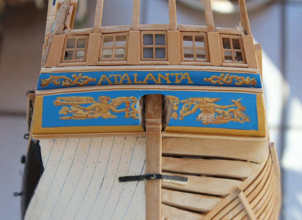
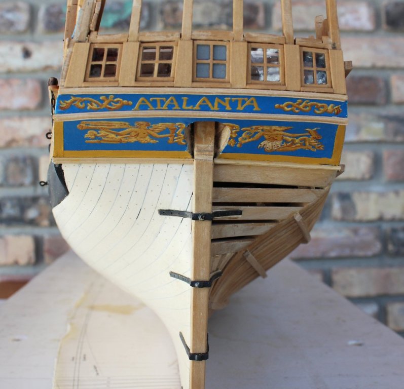
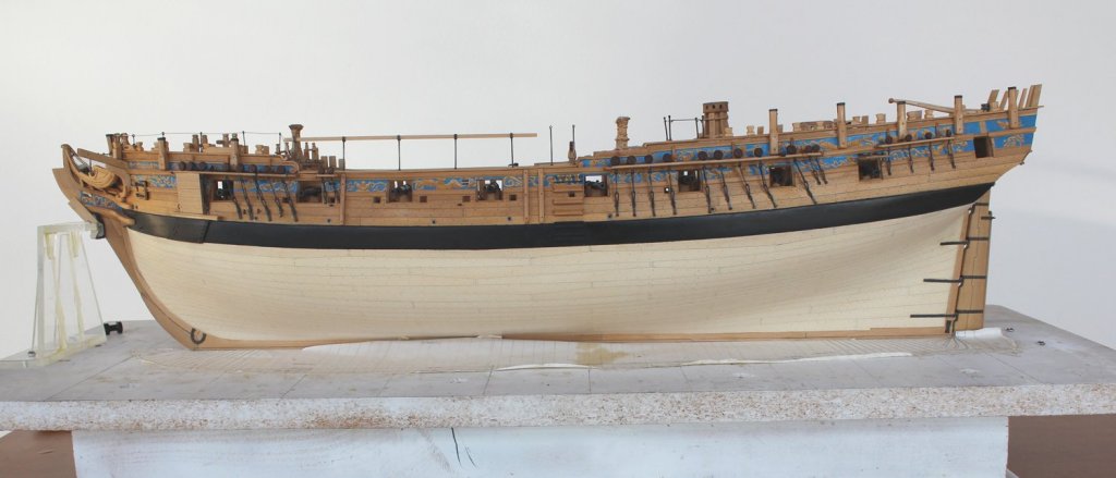
I started the carving for the taffarel. Let's just say that it will be a slow process. I need to be in the correct mood to concentrate on it. Therefore, I will work on other aspects of the ship while carving continues. The next thing to tackle is the counter artwork. The upper counter has the name ATALANTA and some acanthus leaves. The artwork was done in the same manner as the side of the ship. The background was spray painted. The artwork was drawn onto the background with transfer paper. The painting was done with artist acrylics. The print shows the lettering as "artsy" rather than block lettering. This did not seem right to me so I attempted to make the lettering more consistent. I could not find any information about the two men on the lower counter. The man on the port side is blowing a horn and the man on the starboard side is holding a caduceus in his right hand and what looks like a gourd in his left hand. I do not think this represents the two prospective suitors of Atalanta because they are seen in the carvings above. After they were installed I tried to freehand paint the edging on the lower counter. This was an utter failure and I had to remove all of that paint without damaging anything. The best alternative for me was to paint some tissue paper with yellow ochre, cut out strips and glue them onto the blue background. I think it looks reasonably good and will look better after I install the rudder.
-
Martin, I simply duplicated to the best of my ability the design on the print. OK, there were minor changes when the knife slipped and I had to go with Plan B!
-
Thanks to everyone for the likes. John, that is sheet mica in the window lights.
-
Mike, I thing the case looks phenomenal. It is not out of proportion to the hull. What makes it look "heavy" is the skinny TV next to it. The black color of the TV recedes into the wall visually, making the case more prominent. I think your only solution is to get a bigger TV!
- 955 replies
-
- 7
-
-
- hahn
- oliver cromwell
- (and 1 more)
-
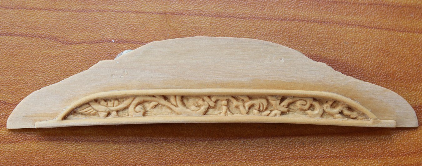
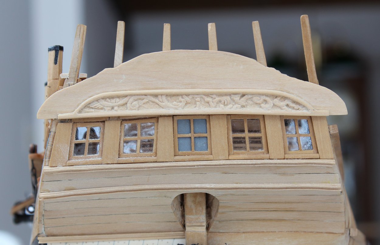
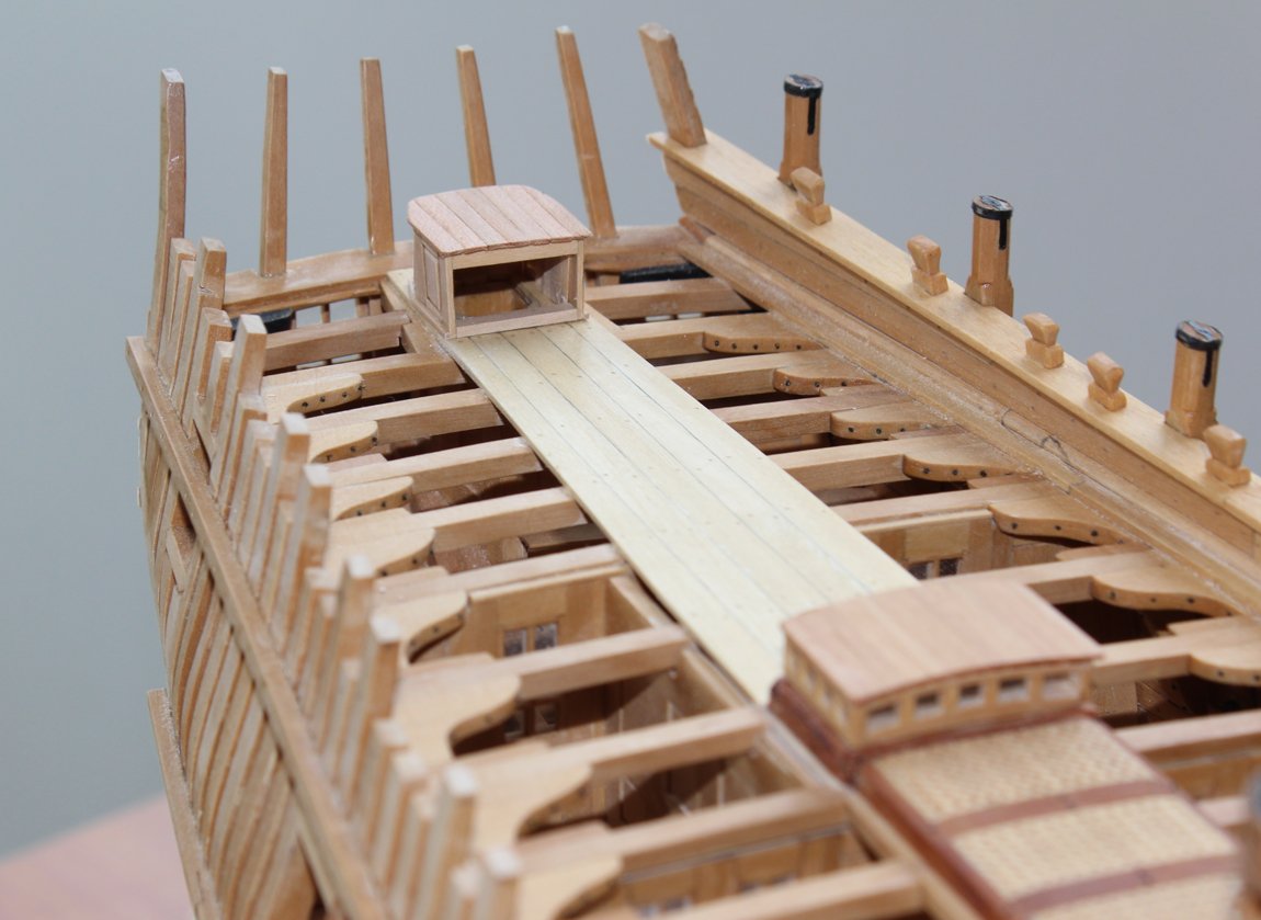
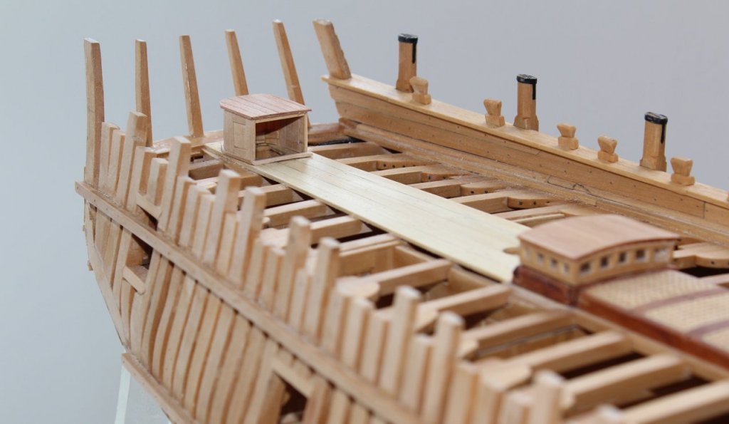
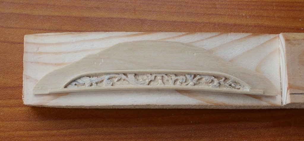
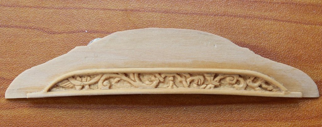
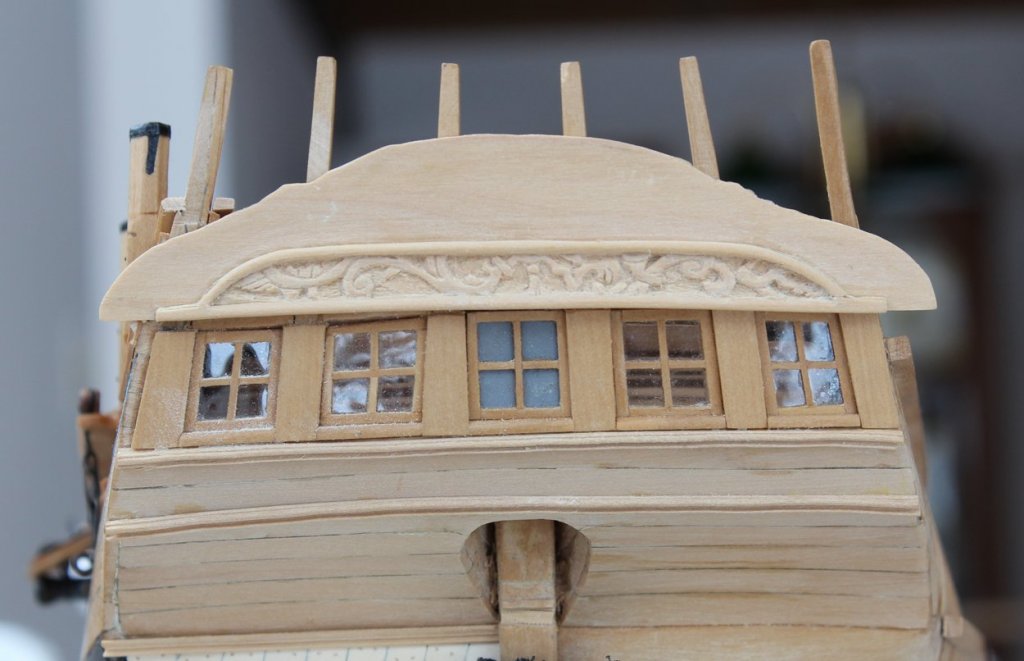
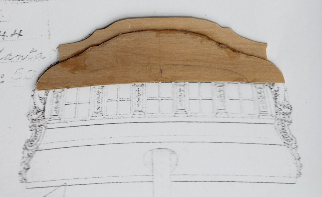
I went back to the rudderhead cover to see where my errors were. The faces of the cover were all made perpendicular to the water line. I mistakenly assumed that the individual faces would be parallelograms rather than rectangles and shaped the inserts accordingly. Looking back at it after a few weeks, I could only do one thing...recycle. I made up a new cover with all the faces rectangular. I am much happier with the result. I kept looking at the taffarel thinking how much taller it seemed from the one in TFFM II. Then, as I was thumbing through the last few pages, I discovered my problem. Atalanta was equipped with a taffarel fife rail and the plan was showing the superior extent of that rail. If one looks very carefully at the plan (in the previous post) it is possible to barely discern the counter timbers. I am assuming that the space above the capping rail (the rail that caps the taffarel) and below the taffarel fife rail was open to the air and not solid. So I removed the wood above the capping rail on my taffarel blank. The cove is the area above the windows, surrounded by molding. This is filled with bas relief carving as seen in the plan above. I used transfer paper to copy the design onto the cove and using a combination of #11 scalpel blades and micro-drill bits carved the decoration. Having done the carving project developed by Chuck and sold by the NRG made this go a lot quicker. I tack glued the assembly onto the curved jig to facilitate the carving. This provided me with a handle to hold the assembly while keeping my hands out of the way. I used my ancient Emesco drill since wood carves nicely at low speed. My drill bits are used bits from the OR. By hospital policy, I can only use the bits on one patient, so my team is kind enough to resterilize them and give them to me rather than throwing them out. The first picture is the assembly in the jig. After removing from the jig, I wet down the carving to highlight the depth. The last photo shows the assembly tack glued to the counter timbers.
-
I built the rudderhead cover with the faces all perpendicular to the waterline. With the downslope of the deck, it gives the illusion that it is skewed. Should I have made the aft wall perpendicular to the deck line instead?
-
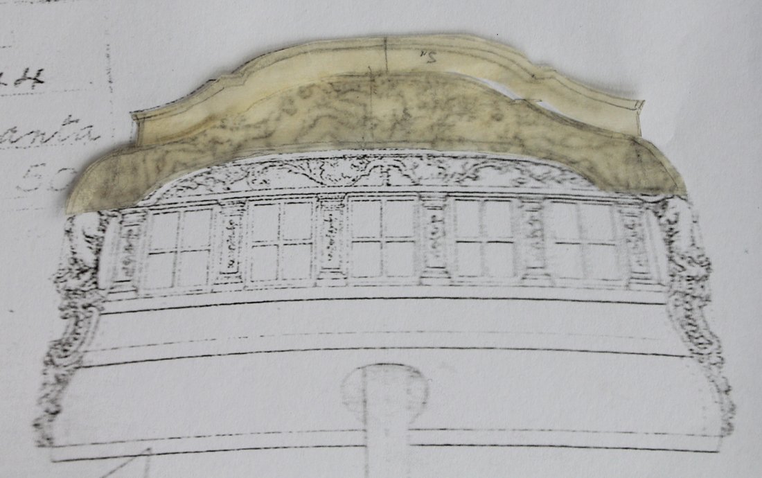
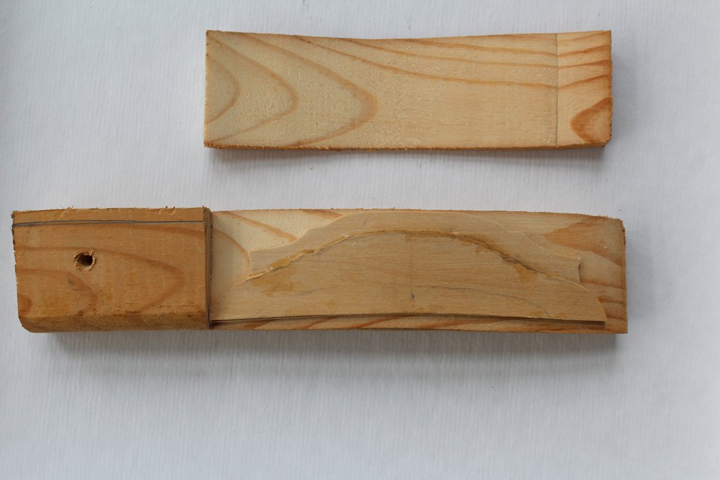
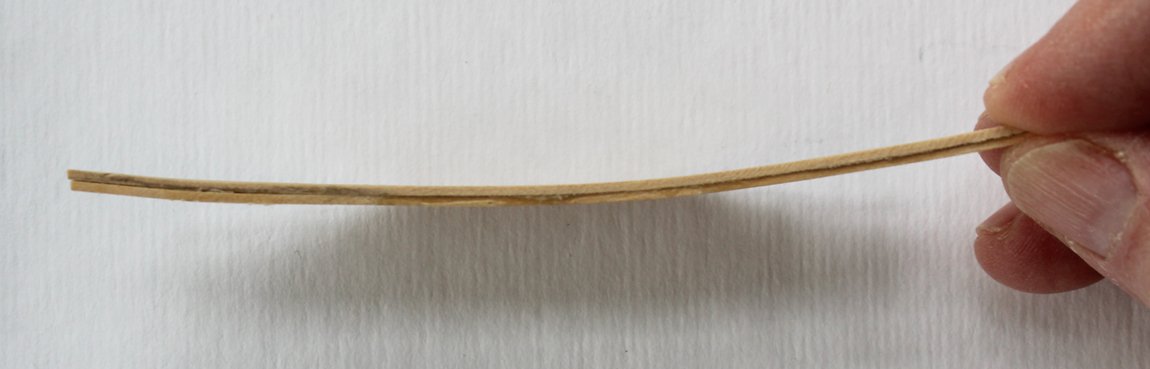
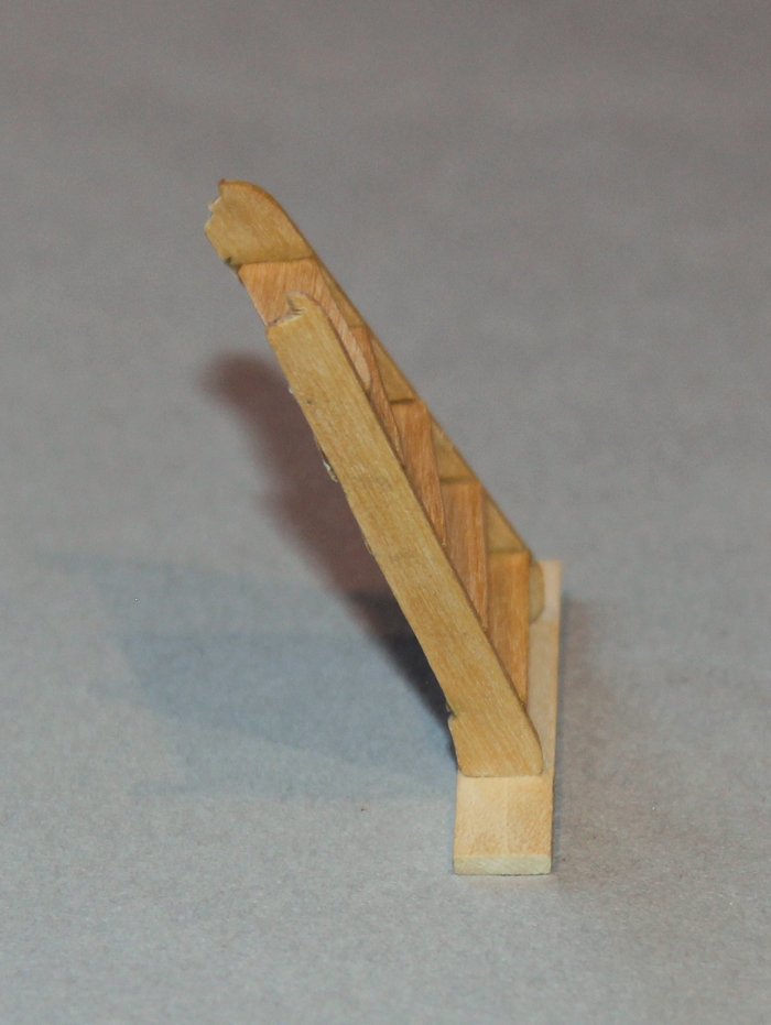
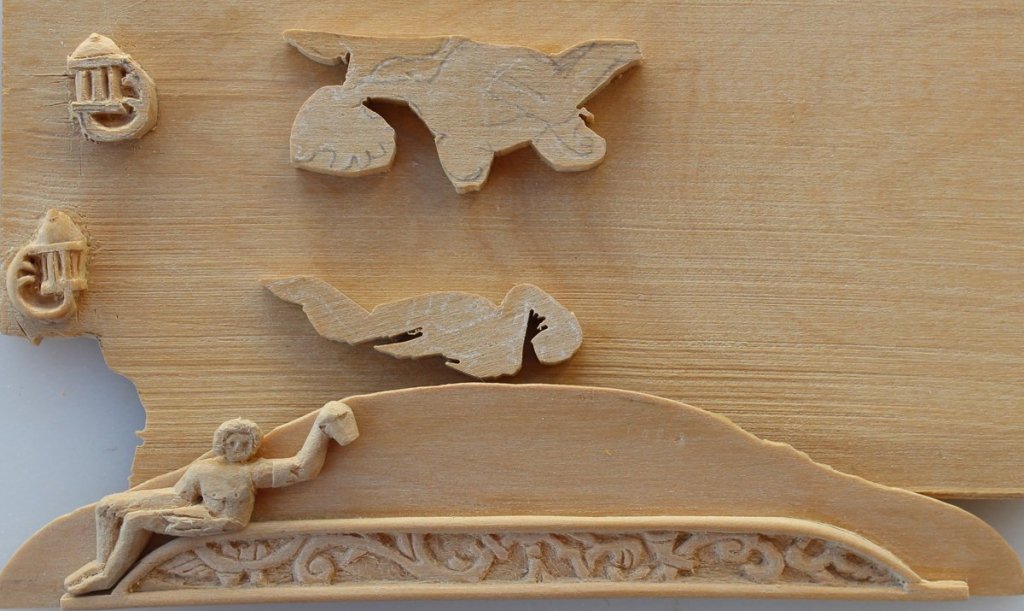
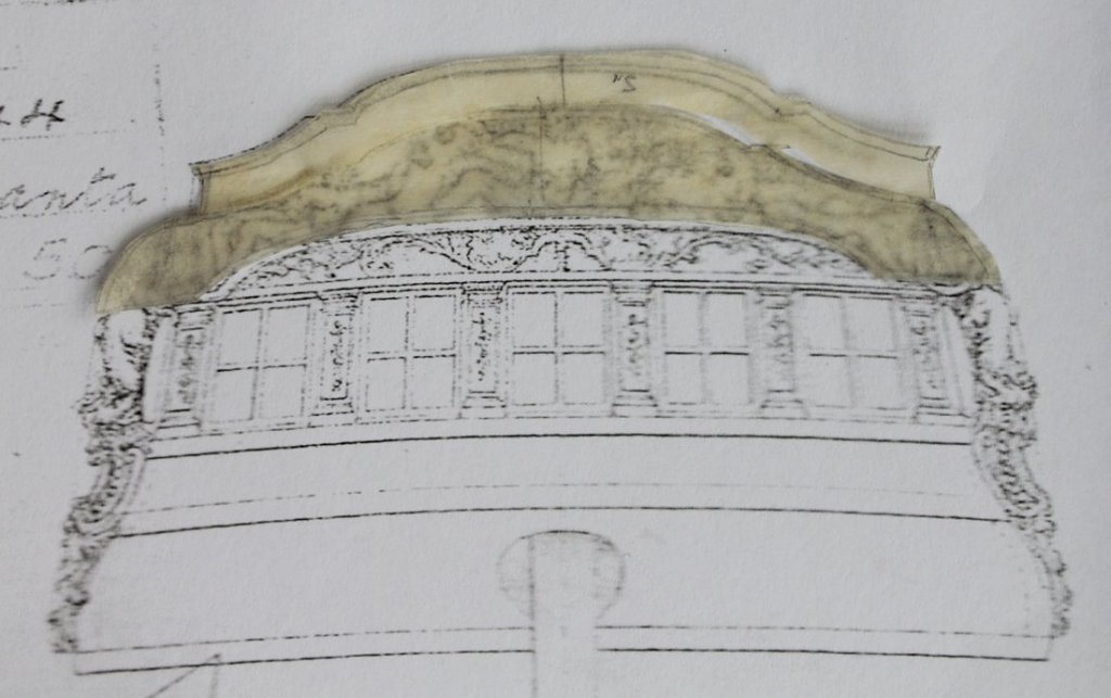
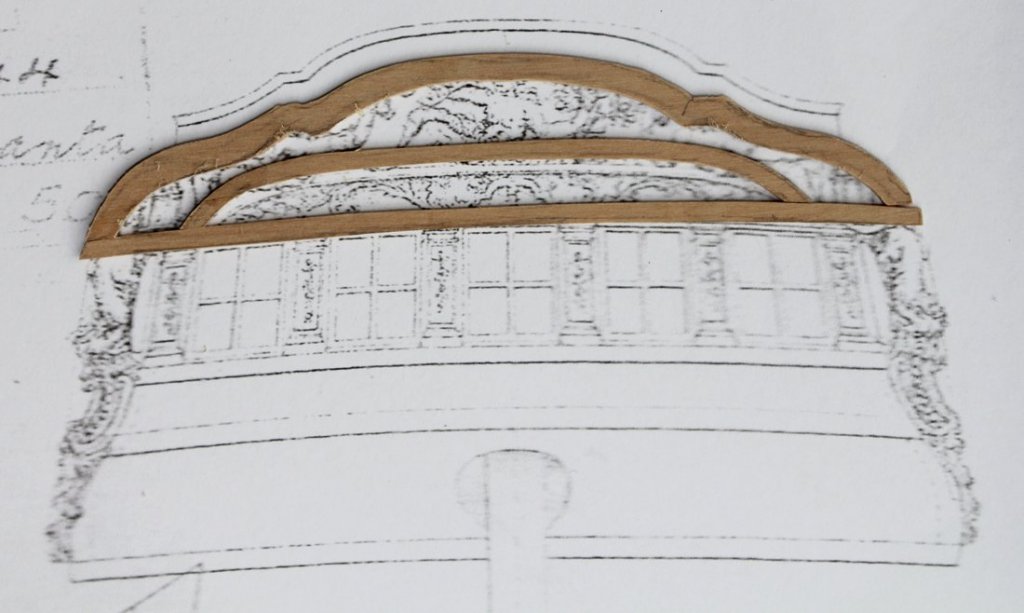
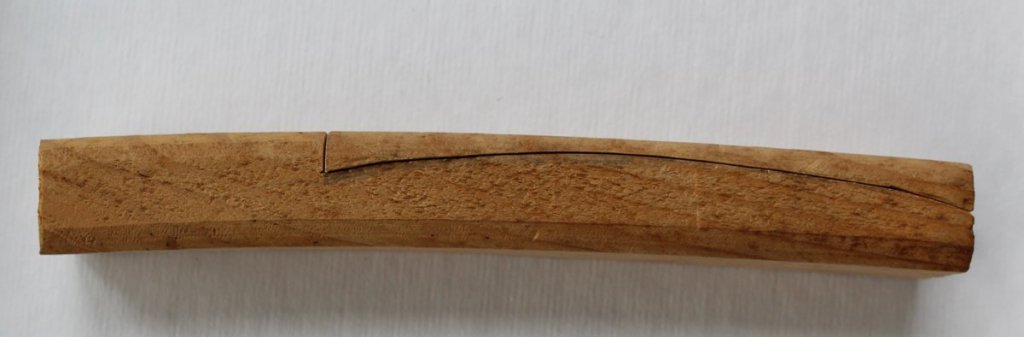
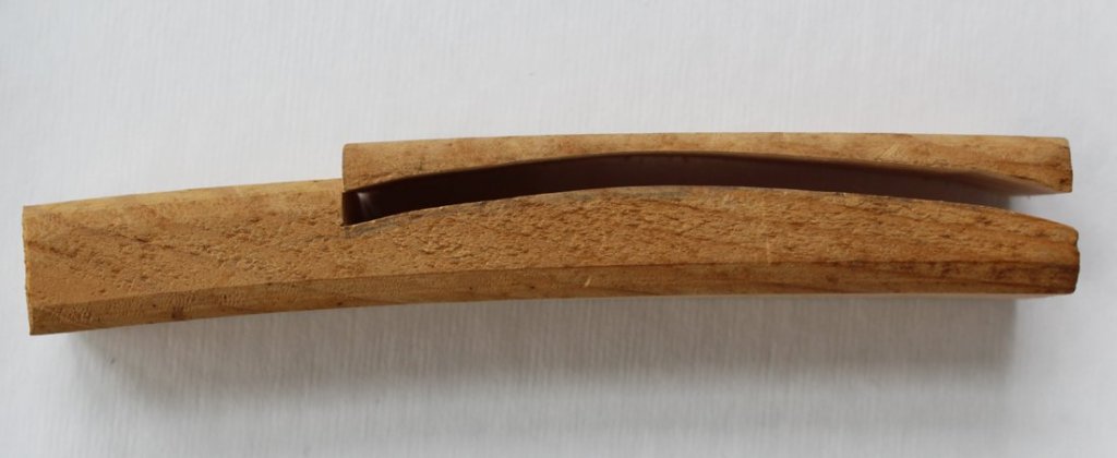
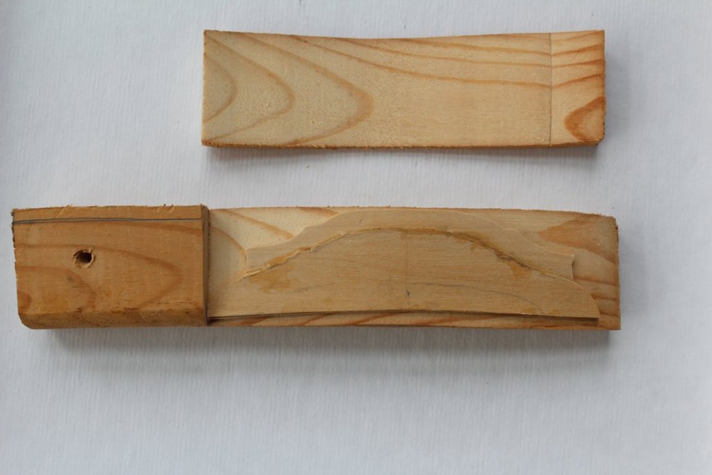
It is time to start construction of the stern structures. I have been dreading this part because of the amount of carving required. Luckily, The plans for Atalanta show the carvings in reasonable detail. Whether I can duplicate them...time will tell. The taffarel is essentially a large painted board of multiple thicknesses onto which the carvings are placed. It is curved to match the curvature of the stern of the ship. The first step was to make a pattern of the curvature. This template was then drawn onto a piece of 1.5" x 3" pine and the curvature was cut out with the scroll saw. This gave me a press into which the various layers of wood will be places to laminate them in the correct curve. By cutting the pine this way I left myself a handle to hold onto. I constructed mine from three layers of 2" board with the grain athwartship. To be completely accurate, the image drawn on the plan must be enlarged to compensate for the fact that one is viewing it end-on. I took multiple measurements from the shear plan and determined that there was 2% inferior/superior difference and a 3% port/starboard difference. This fell within the just-make-it-a-scooch-bigger category, which is what I did by enlarging the drawing 2% on the copier. I took tracings for the overall size of the taffarel and started by cutting out the large base board. I then cut the tracing into smaller pieces representing the remaining boards. It was time to start gluing everything together. I generously applied glue to the two large boards and used bar clamps to hold them until the glue was very tacky. This helped to prevent the boards slipping after being put into the press. I lined the press with Saran Wrap to keep the assembly from adhering to the press. They were kept in the press overnight. The third layer is next and then on to the final shaping.

-
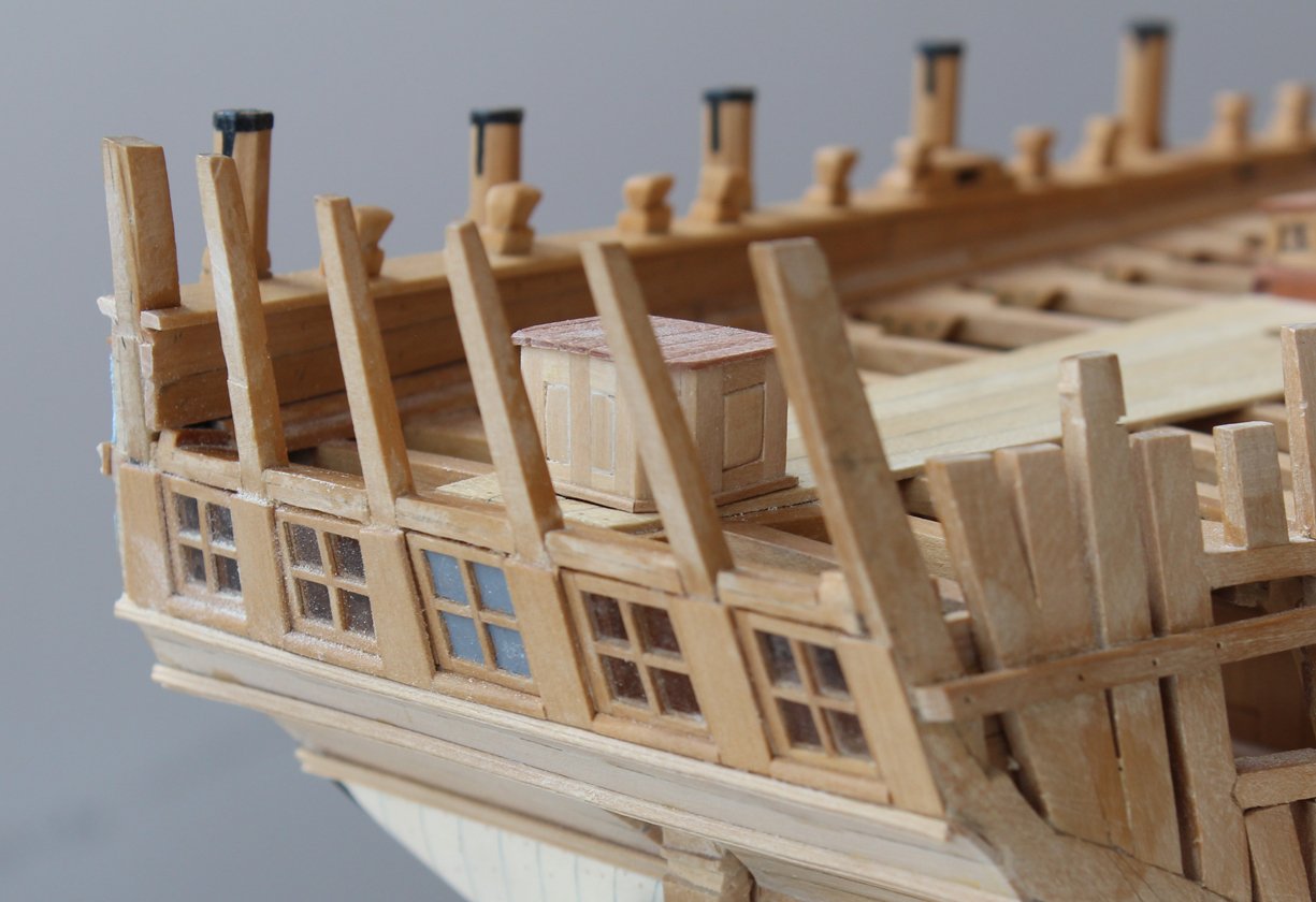
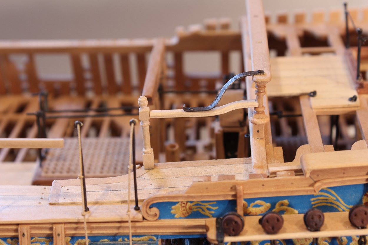
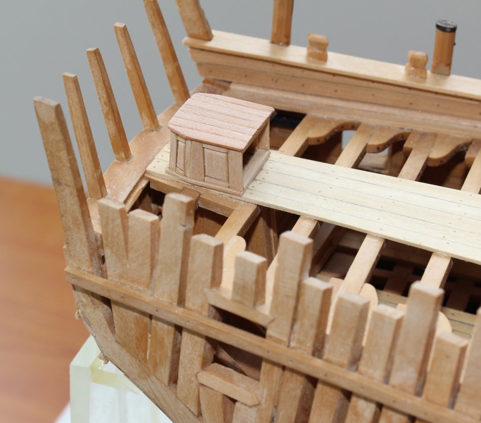
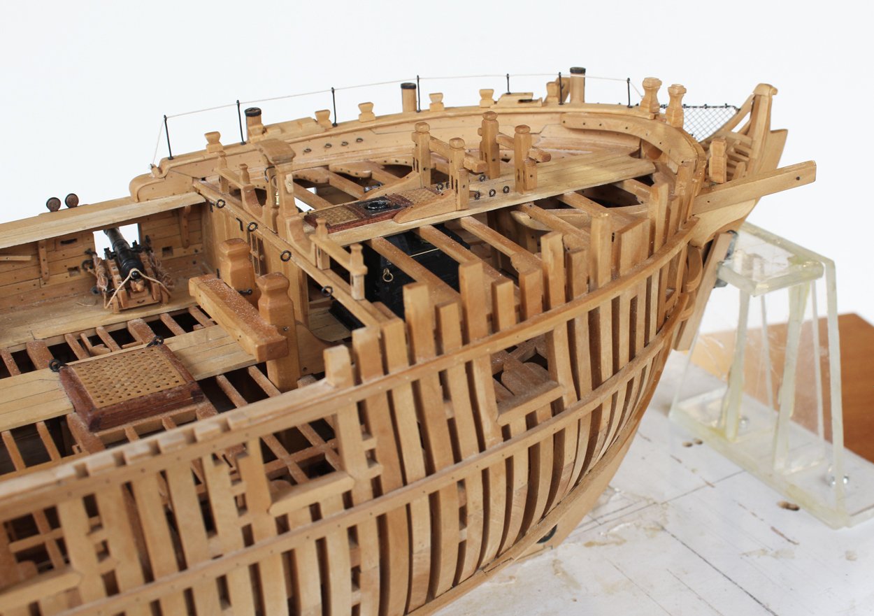
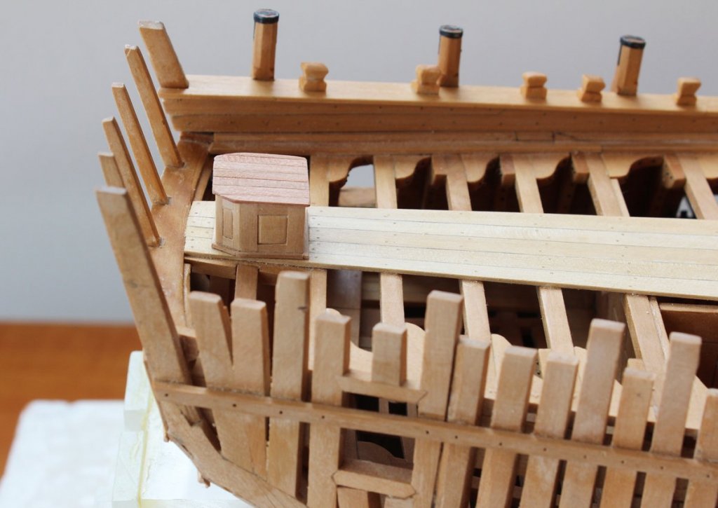
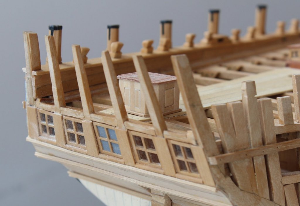
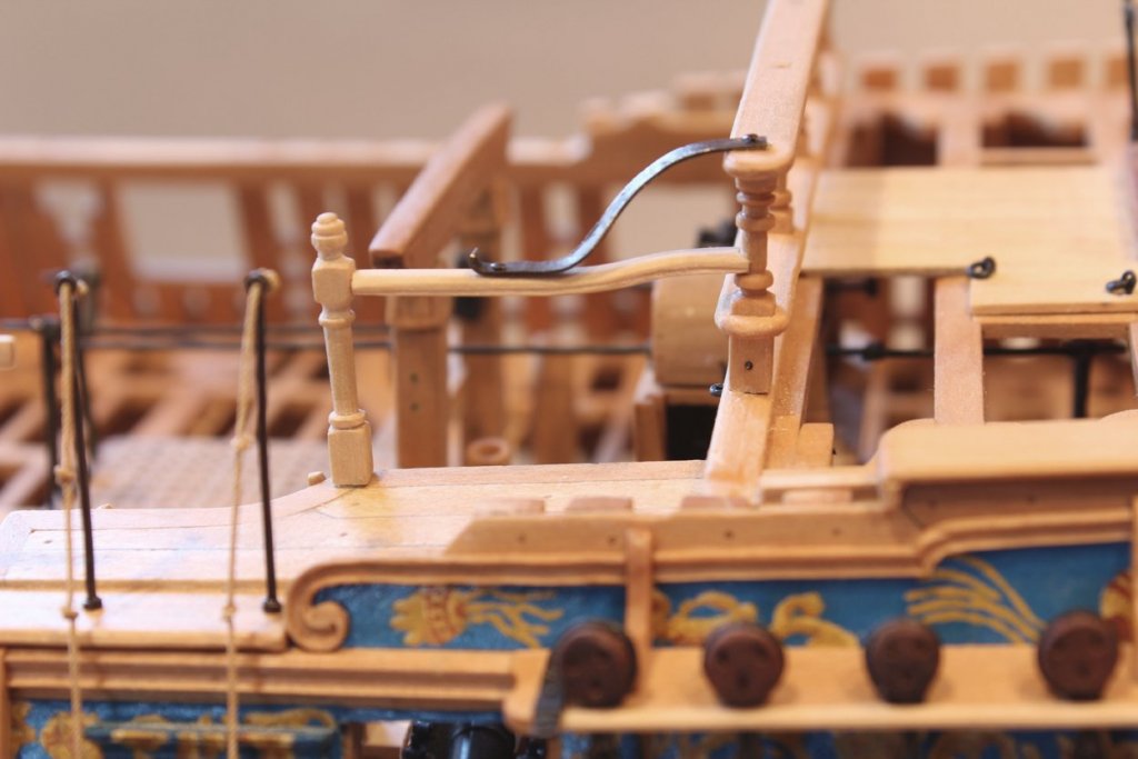
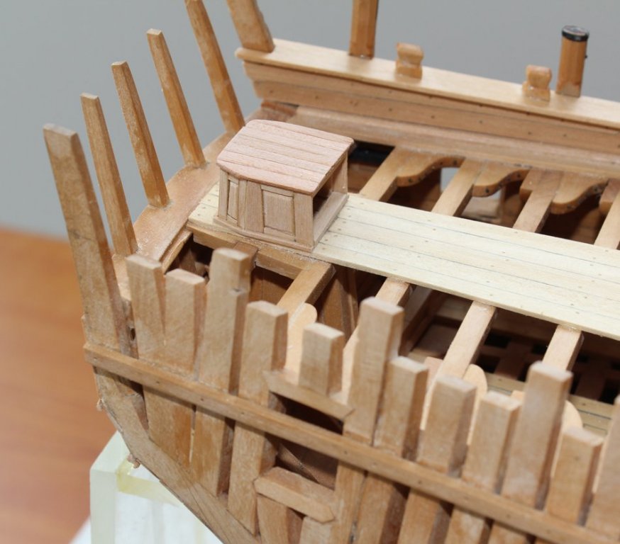
The fixed gangway newel post was turned on the lathe. It is mortised into the deck. The rail between the newel post and quarter deck breastwork is curved and had a decorative shape cut into both sides of the rail. I made mine look like the handrail on my staircase at home. There is an iron strap between the rail and the breastwork rail. It is bolted at both ends. This piece took me many hours to make correctly. It curves in an S-shape between the two rails. It curves outwards as it approached the gangway newel post. The problem is that the breastwork rail is curved to match the deck camber and the gangway railing is parallel to the waterline. This little difference (for myself at least) resulted in the curved portion of the iron strap to appear rotated outboard. The final fix was to overcompensate for the breastwork rail camber when cutting out the strap, allowing it to remain parallel to the waterline throughout, except where it bolted to the breastwork rail. At this point I discovered that the breastwork rail assembly was not exactly perpendicular to the waterline (as seen in the first picture). I removed the entire assembly, only breaking one post, and reinstalled it correctly. The second picture was taken after reassembly. I also installed entering ropes onto the entry stanchions. They are stiffened with very dilute white glue. The rudderhead is protected with a cover. The plans show the shape for the cover, basically a three-sided box with the aft corners rounded off with a short wall. The roof is made of cherry. I have removed the rail in preparation for beginning construction of the stern structures.


-
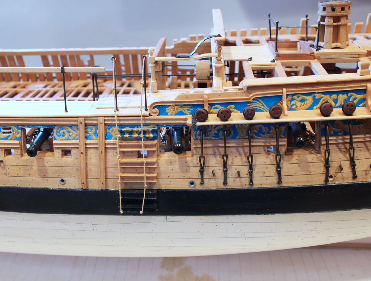
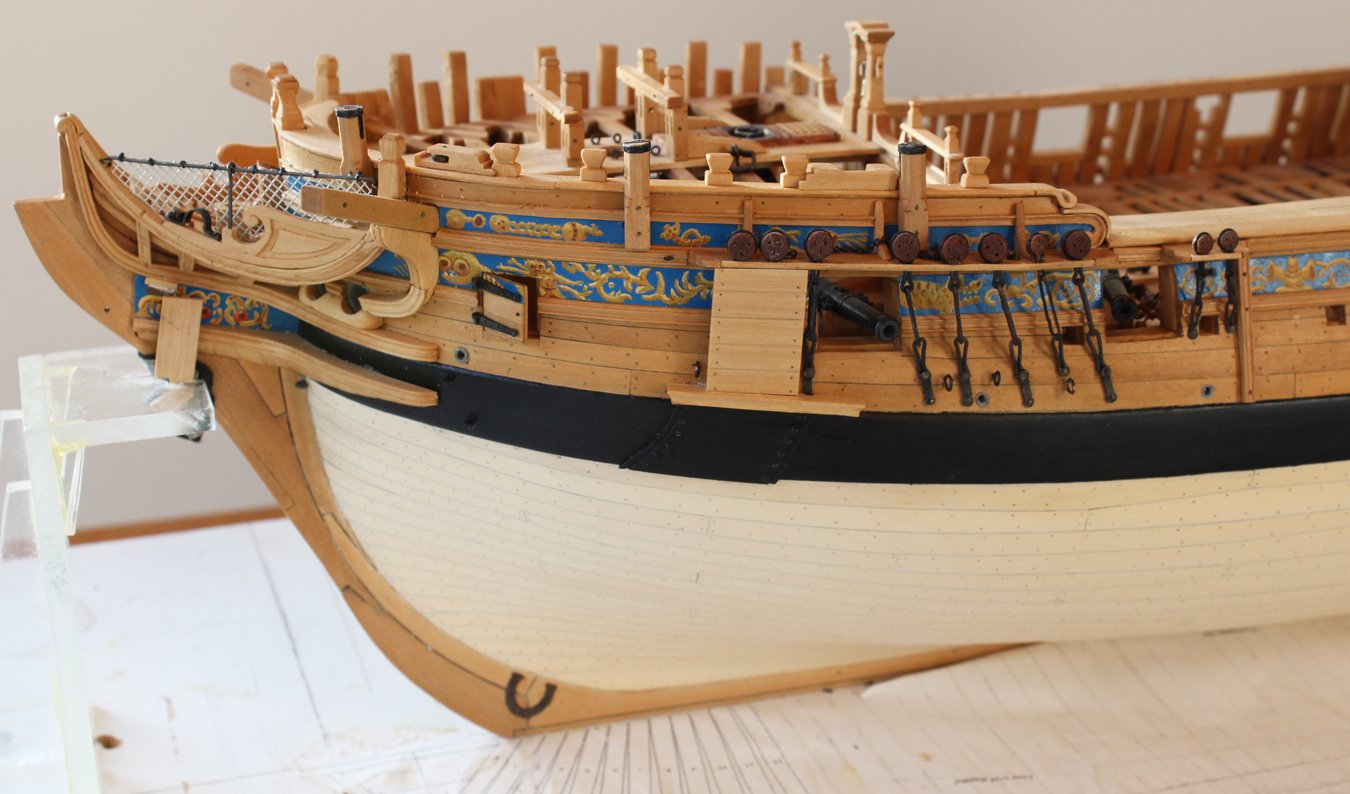
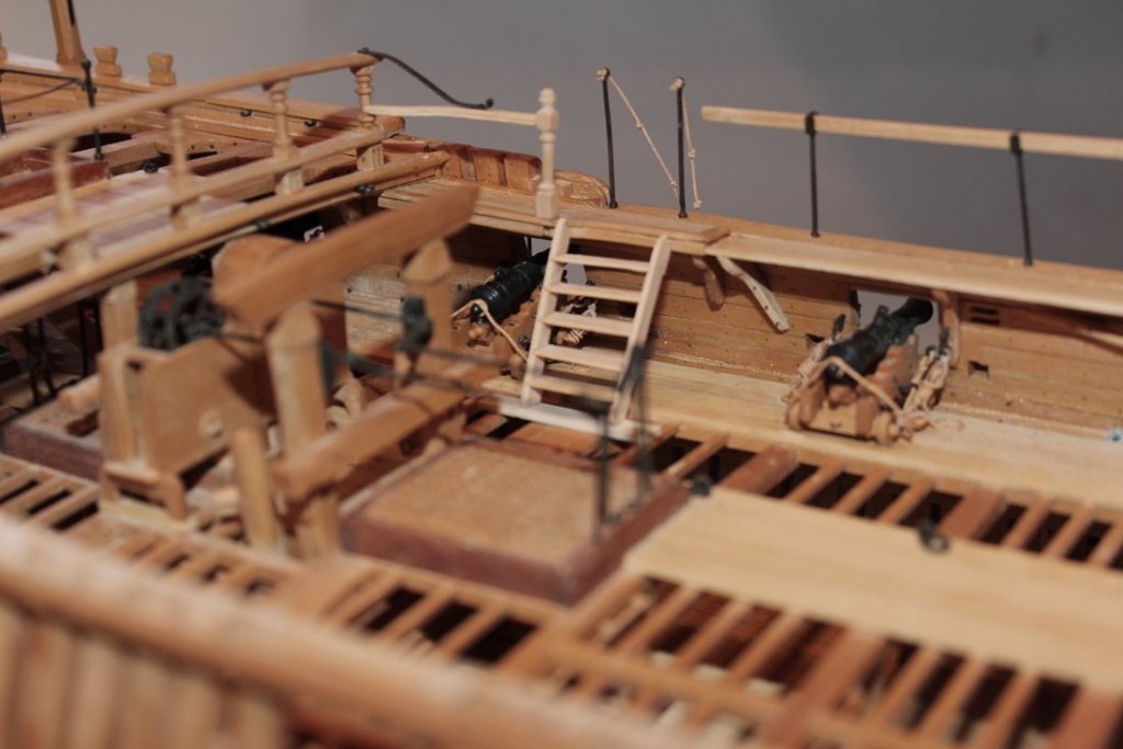
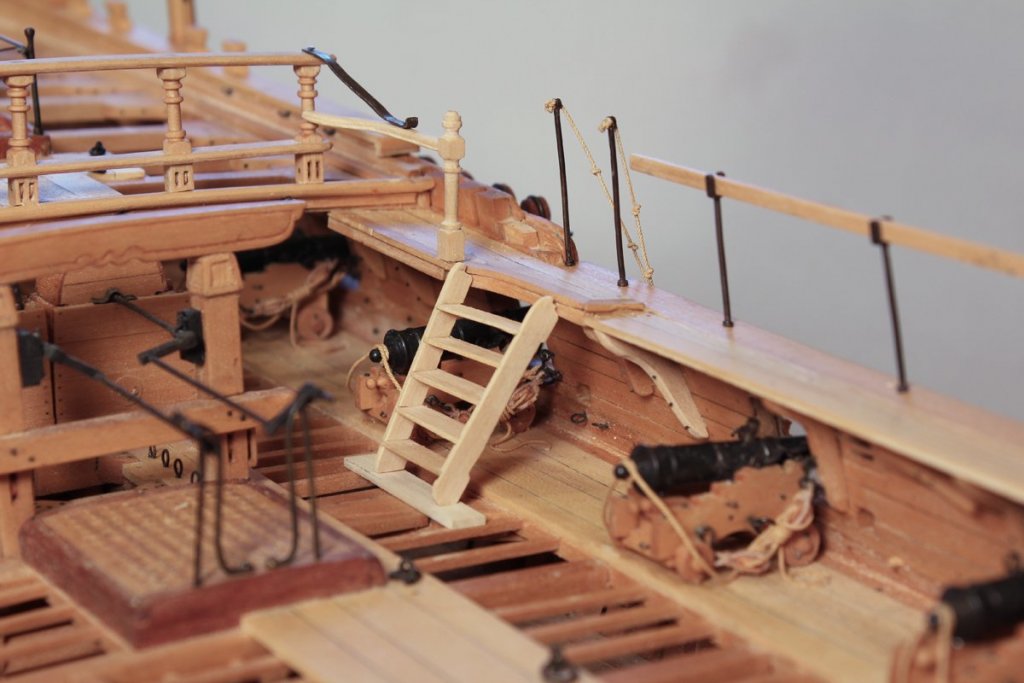
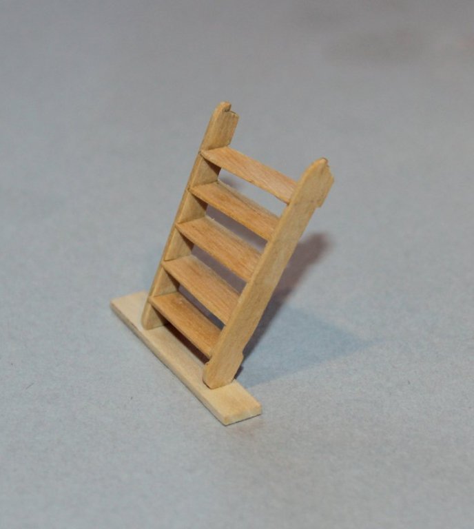
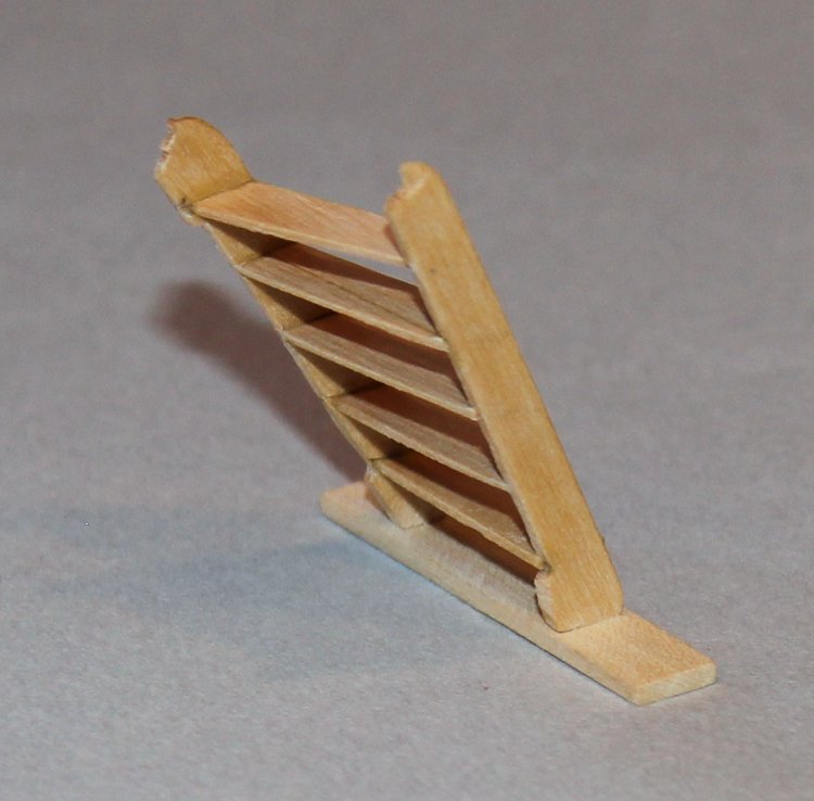
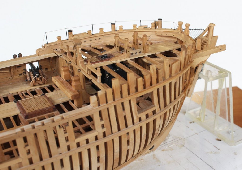
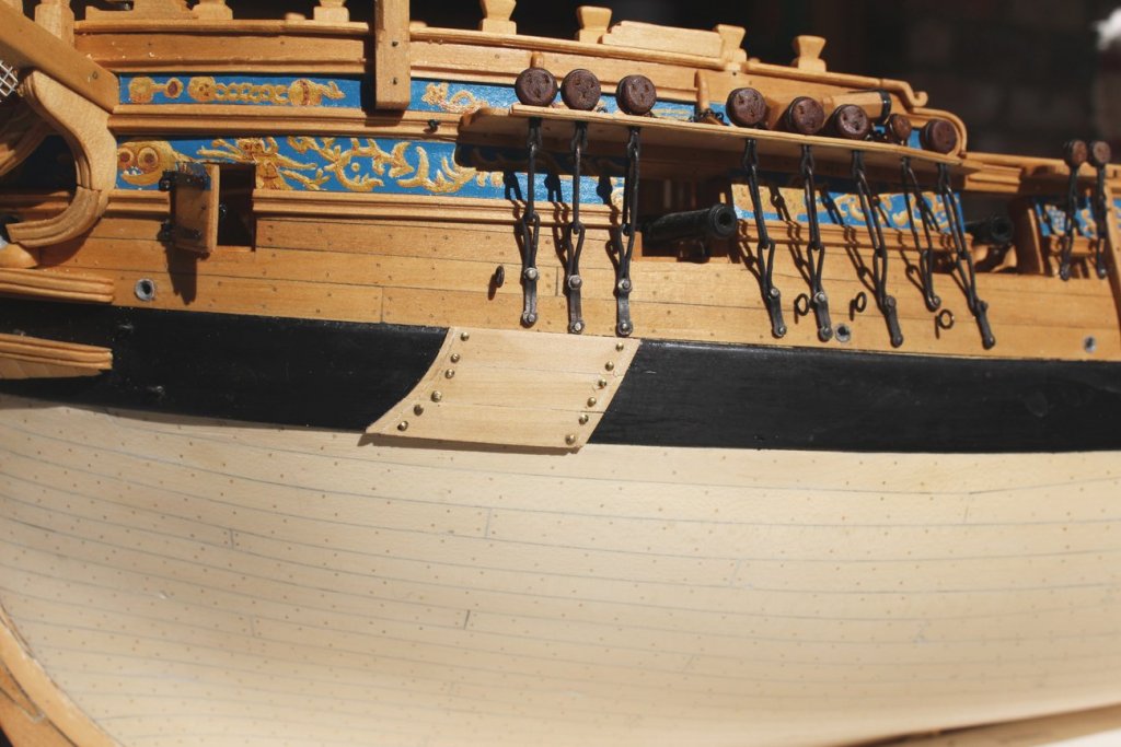
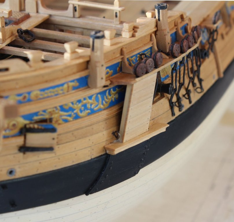
I cannot believe it has been so long since the last post. I found myself being very critical about the way certain things looked or fit together and have been spending a lot of time remaking various items. In between the remaking projects I have gotten in a little bit of new work. The main and mizzen deadeyes and chains have been installed. The mizzen chains do not have chain plates. The preventer eyebolts and swivel bolt below the last gunport have also been installed. There is a stairway leading down to the deck from the fixed part of the gangway. In TFFM David discusses installing a stairway with parallel treads vs. winding steps. Since the interior aspect of the gangway is curved, I decided to build a winding stairway. This is easier said than done! The uprights are different lengths and sit at different angles to the deck. They articulate with the gangway with a notch at their tops. Once I was happy with the uprights I installed oversized treads. After they had dried I used a drum sander on the Dremel to shape them. I will defer permanent installation until later in the build to preserve access to the cannon to repair them (again!).


-
That is how I do it. Between sharpenings, I also hone the chisel with a leather strop.
-
Beautiful work. When I was deciding how to color my wales I tried using the dye and did the cost:benefit analysis. It looks great but one mistake and the damage is irreparable. I used Chuck's suggestion and painted the wale with several (4 or 5 as I recall) thin coats of acrylic paint, sanding or scraping between each coat. This is a lot easier to touch up from the inevitable bumps and bruises.
-
Please do yourself a favor. Go to the Articles Database section. There you will find a section on Planking and Framing. There are several excellent articles on hull planking. Also, I hope you do not plan on leaving the nails in the planks. Even though this is a double planked hull (I presume) it is very difficult to file down those nailheads without causing damage.
-
Incredible!
-
I also have a small work space so I understand your dilemma. I opted for a scroll saw. It is on a stand and I utilize the space under the saw for storage. As an alternative, when you do not need the saw, store it in the garage. I would suggest a full-sized scroll saw since they have significantly more power. The deeper throat on a full-sized saw also comes in handy when cutting longer pieces and when laying out several pieces on a larger sheet of wood.
-
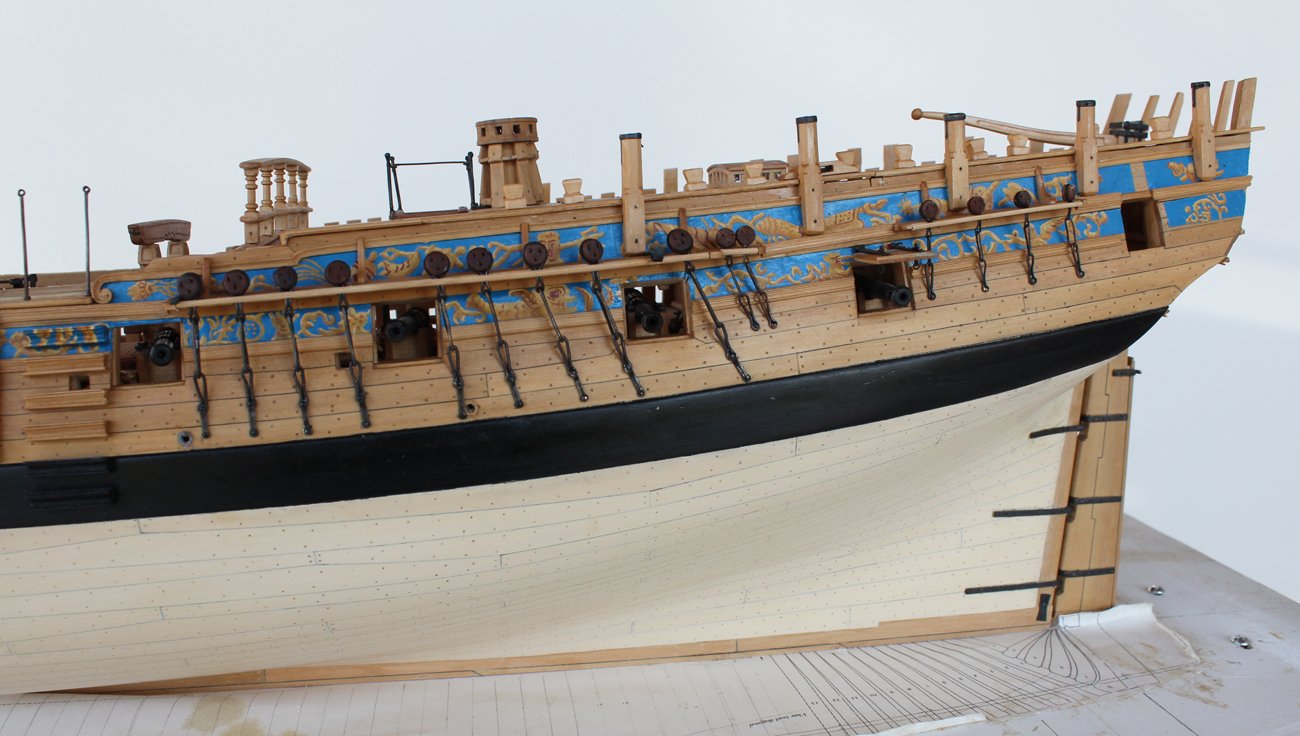
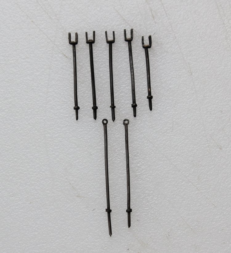
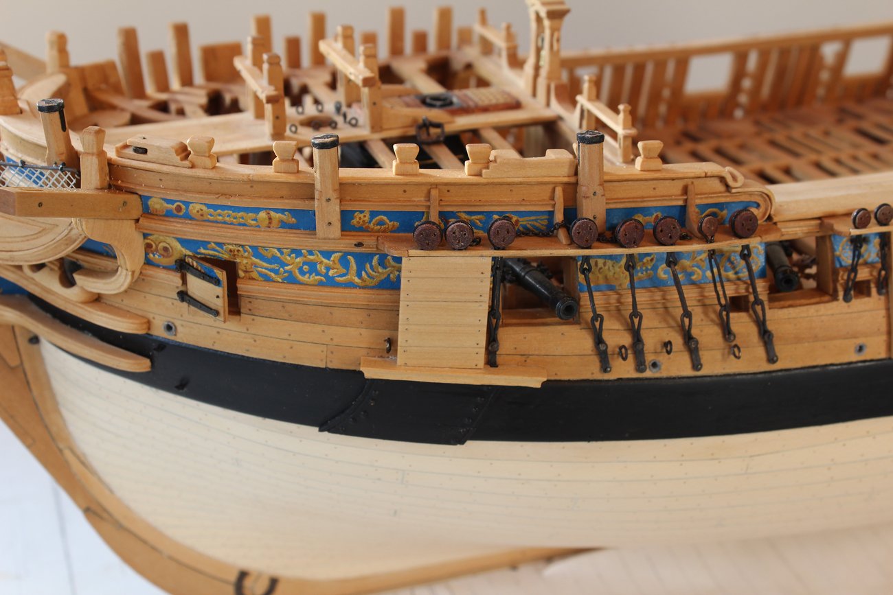
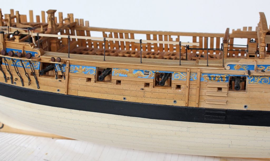
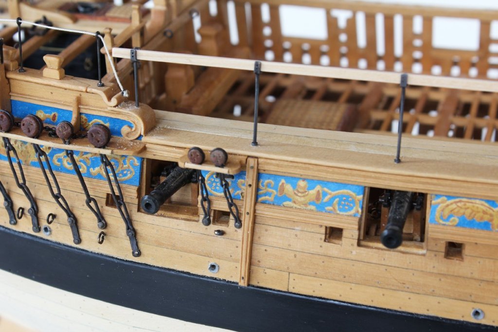
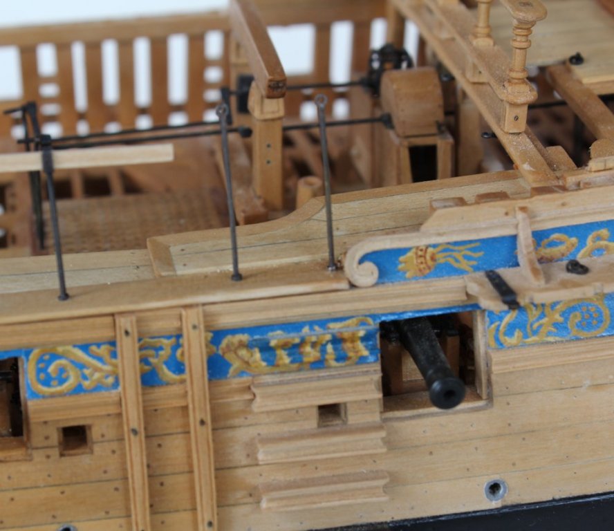
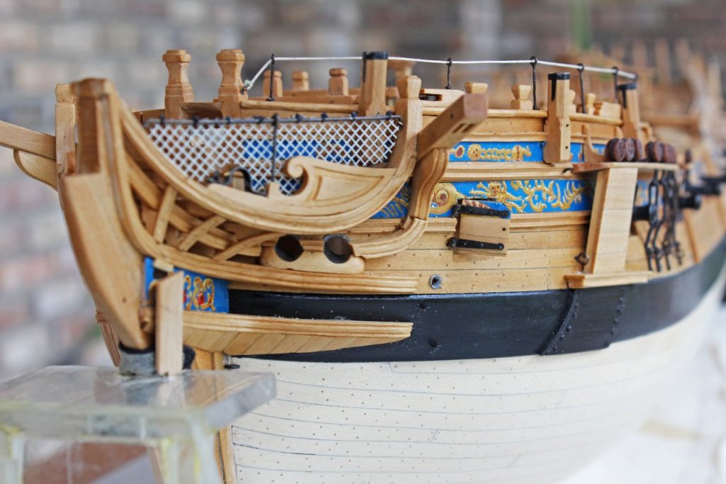
At the waist there are five stanchions to support the rough-tree rail and two stanchions for the entering ropes. In contrast to the forecastle stanchions, these have a U-bracket top instead of a loop. The U-bracket is drilled for pins to secure the rail. The rail itself is 2" x 4". When I was making these I referred to TFFM Vol 2 and thought that I saw each side of the bracket drilled for two pins. After everything was secured I went back to the drawing and discovered that only one hole is represented. After about 30 seconds of soul searching I decided that I liked the look of the two holes and left them as is. I have not decided whether to put a fastener through the holes or not. The entry stanchions are very similar to the forecastle stanchions, except taller.

-
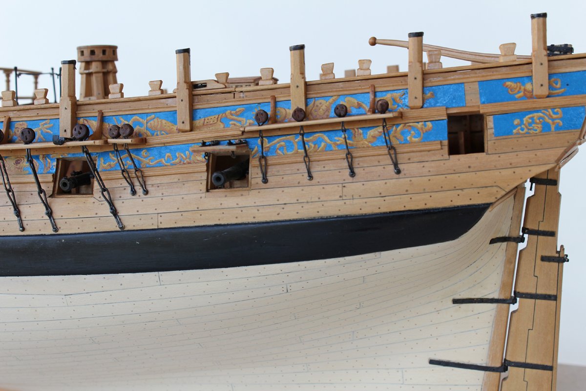
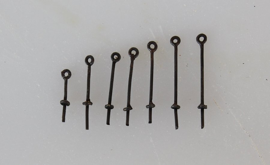
There are quite a number of stanchions along the planksheer. On the forecastle, seven stanchions support a man rope. They were made out of 1 1/4" iron and had an eye at the top. The base swelled to a collar where it met the planksheer. Each of these is a different height to compensate for the upward curvature of the forecastle. These were made with brass wire. I used small pieces of brass tubing to represent the eye and threaded tubing onto the stanchion to represent the collar. Both these pieces were silver soldered to the brass wire. They were blackened and installed onto the planksheer. A rope was threaded through the eyes and secured to the bollard timber forward and to the planksheer aft. There is a slight dip in the rope at the third stanchion from the bow but it fits so tightly in the hole that I cannot safely remove it.
-
Bending Trim planks.
tlevine replied to Ed Meyer's topic in Building, Framing, Planking and plating a ships hull and deck
What species of wood are you trying to bend and what are you using it for? One thing you might consider doing is laminating two thinner strips of wood as they will be easier to work with. -
Several years ago I attended a workshop after the Buffalo NRG meeting about how to build the cutter for a Swan class ship. At the time, I was building Hannah, using Hahn's techniques. In those 2 1/2 days I learned more than I had learned in the previous several years. You gave me the confidence to take a blind leap and build a fully framed model. I can never thank you gentlemen enough.
-
The forecastle deck probably had stanchions supporting a line to which netting is fixed. The object was to prevent sailors from being as easily swept overboard. I have been unable to find any information as to whether this netting would be located outside or inside of the timberheads. Any thoughts? The contemporary model of Atalanta does not show these stanchions.
-
Swann-Morton Scapel
tlevine replied to Landlocked123's topic in Modeling tools and Workshop Equipment
Instrument tying is often superior to hand tying. It allows me to get into tight areas that even my small hands would find difficult. Once you get the feel for the correct amount tension to apply for the type and weight of the material, it is just as secure as hand tying. -
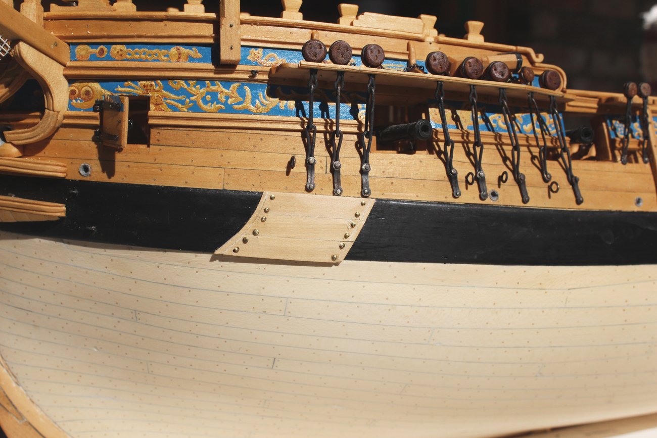
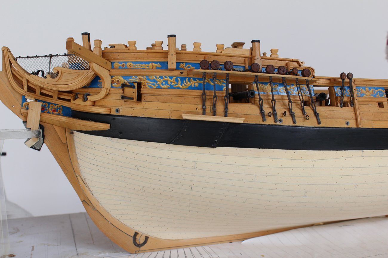
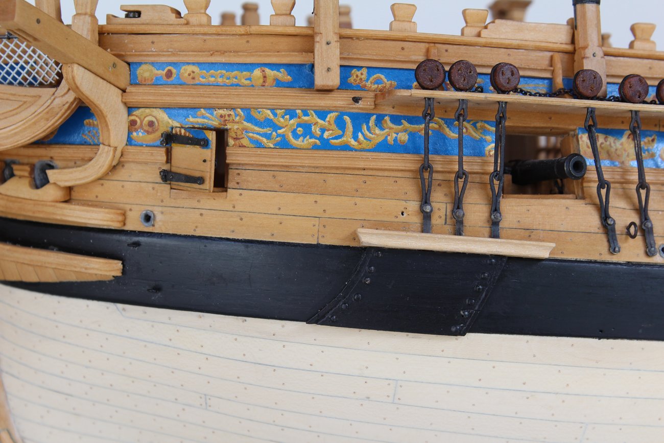
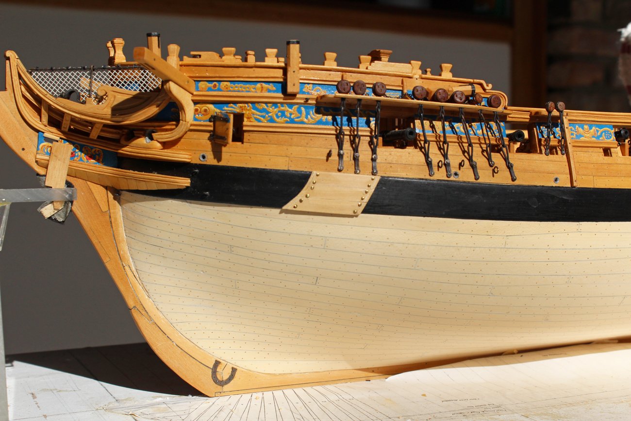
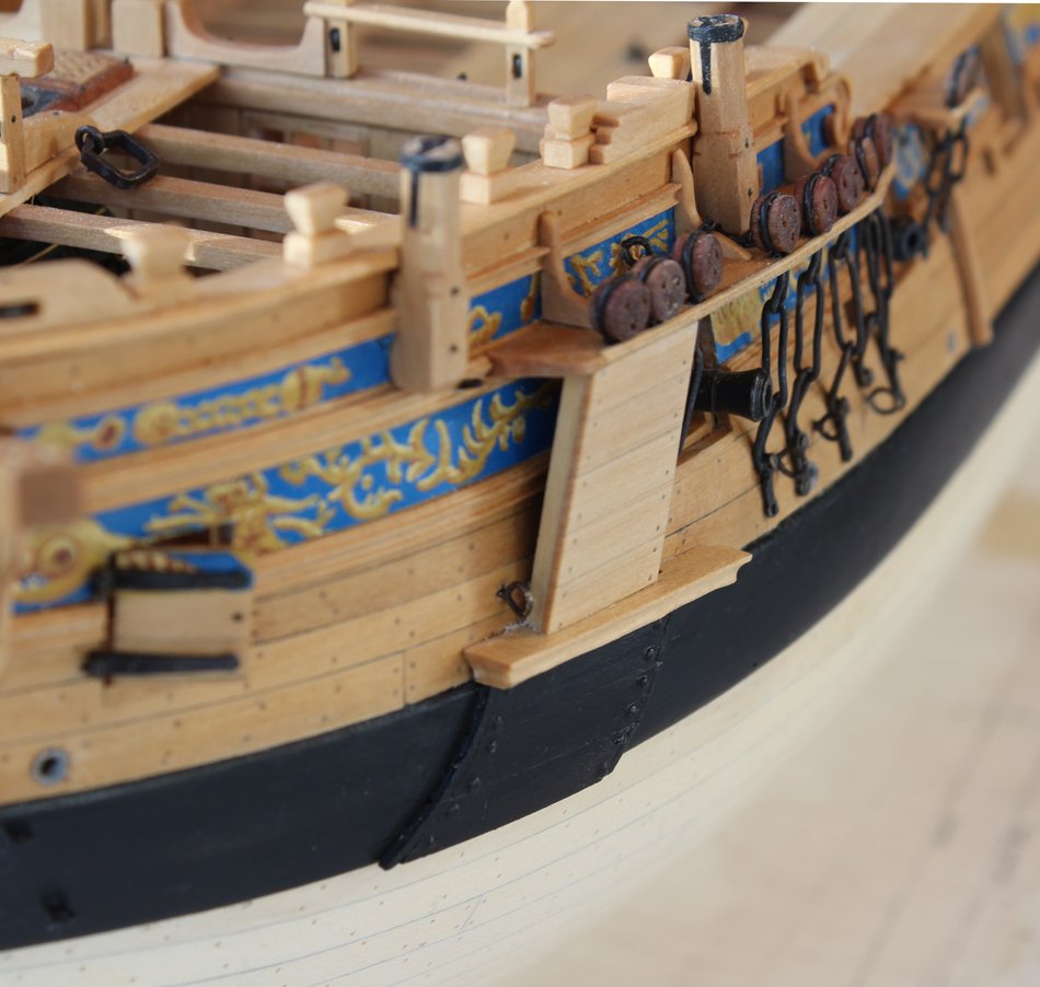
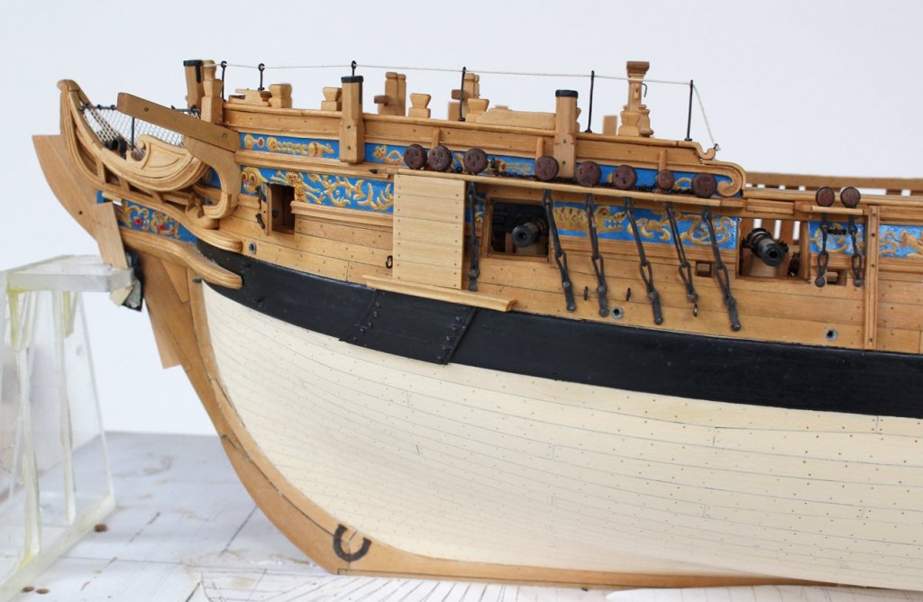
Ed, never apologize for your books. They are bibles for many of us. The covering boards and bill boards are an attempt to prevent injury to the hull and chain plates while hoisting the anchor. Both of these structures are designed to be easily replaced. On the Swan class the lining overlaps the main wale. There are three of them and they are attached with nails whose heads stand proud for easier removal (I think). There is a decorative groove near the lateral edges. In order to get a smooth run for the groove, I made the lining off the model, gluing the the boards together on a piece of paper for extra support. Then I cut the groove. I removed them from the paper and glued and nailed them to the model. The lower two boards required bending in two planes to fit the wale tightly. After listening to everyone's advice I decided to paint them. I found the appearance of the bright wood garish against the black wale and decided any commanding officer would feel the same way. There is a molded platform on top of the lining is wide enough to allow a man to stand on it. Access would be through the gun port. The bill board has two vertical stanchions to which the boards are attached.


-
US Brig Syren by knightyo
tlevine replied to knightyo's topic in - Build logs for subjects built 1801 - 1850
I vote for the pear. The basswood is too light. Once the finish is applied, the end grain will give it subtle contrast.